EP2500459B1 - Procédé et dispositif de lavage, en particulier de pièces de linge - Google Patents
Procédé et dispositif de lavage, en particulier de pièces de linge Download PDFInfo
- Publication number
- EP2500459B1 EP2500459B1 EP12001271.1A EP12001271A EP2500459B1 EP 2500459 B1 EP2500459 B1 EP 2500459B1 EP 12001271 A EP12001271 A EP 12001271A EP 2500459 B1 EP2500459 B1 EP 2500459B1
- Authority
- EP
- European Patent Office
- Prior art keywords
- treatment liquid
- filter
- drum
- outer drum
- filtered
- Prior art date
- Legal status (The legal status is an assumption and is not a legal conclusion. Google has not performed a legal analysis and makes no representation as to the accuracy of the status listed.)
- Active
Links
Images


Classifications
-
- D—TEXTILES; PAPER
- D06—TREATMENT OF TEXTILES OR THE LIKE; LAUNDERING; FLEXIBLE MATERIALS NOT OTHERWISE PROVIDED FOR
- D06F—LAUNDERING, DRYING, IRONING, PRESSING OR FOLDING TEXTILE ARTICLES
- D06F39/00—Details of washing machines not specific to a single type of machines covered by groups D06F9/00 - D06F27/00
- D06F39/10—Filtering arrangements
-
- D—TEXTILES; PAPER
- D06—TREATMENT OF TEXTILES OR THE LIKE; LAUNDERING; FLEXIBLE MATERIALS NOT OTHERWISE PROVIDED FOR
- D06F—LAUNDERING, DRYING, IRONING, PRESSING OR FOLDING TEXTILE ARTICLES
- D06F31/00—Washing installations comprising an assembly of several washing machines or washing units, e.g. continuous flow assemblies
- D06F31/005—Washing installations comprising an assembly of several washing machines or washing units, e.g. continuous flow assemblies consisting of one or more rotating drums through which the laundry passes in a continuous flow
-
- D—TEXTILES; PAPER
- D06—TREATMENT OF TEXTILES OR THE LIKE; LAUNDERING; FLEXIBLE MATERIALS NOT OTHERWISE PROVIDED FOR
- D06F—LAUNDERING, DRYING, IRONING, PRESSING OR FOLDING TEXTILE ARTICLES
- D06F35/00—Washing machines, apparatus, or methods not otherwise provided for
- D06F35/005—Methods for washing, rinsing or spin-drying
- D06F35/006—Methods for washing, rinsing or spin-drying for washing or rinsing only
-
- D—TEXTILES; PAPER
- D06—TREATMENT OF TEXTILES OR THE LIKE; LAUNDERING; FLEXIBLE MATERIALS NOT OTHERWISE PROVIDED FOR
- D06F—LAUNDERING, DRYING, IRONING, PRESSING OR FOLDING TEXTILE ARTICLES
- D06F39/00—Details of washing machines not specific to a single type of machines covered by groups D06F9/00 - D06F27/00
- D06F39/08—Liquid supply or discharge arrangements
- D06F39/083—Liquid discharge or recirculation arrangements
Definitions
- the invention relates to a method for washing in particular items of laundry according to the preamble of claim 1. Furthermore, the invention relates to a device for washing laundry in particular according to the preamble of claim 7 (see US-A-20050120758 ).
- Washing namely the actual washing and rinsing, of objects of all kinds, in particular items of laundry, takes place in washing machines which have a drum which can be driven in rotation and is associated with at least one stationary and liquid-tight outer drum.
- the at least one outer drum extends at least over a part of the drum, in particular a part of the length of the rotationally drivable drum.
- the washing takes place with a treatment additive optionally having treatment additives in the drum.
- the treatment liquid occupies only a lower part of the drum.
- the level that is the surface of the treatment liquid
- the treatment liquid is also in the liquid-tight outer drum.
- washing machine which is associated with a filter for filtering out at the bottom of the outer drum collecting heavy impurities from the treatment liquid.
- This washing machine does not provide any possibility of separating lighter impurities from the treatment liquid, in particular foam with lint that is partially bound therein.
- the invention has for its object to provide a method and apparatus for more effective washing and / or rinsing laundry items and other objects.
- a method for achieving this object comprises the measures of claim 1. Accordingly, the treatment liquid, preferably always only a part of the treatment liquid, during the treatment, that is to say in particular the washing and rinsing of the laundry items or other objects, outside the drum and the at least one associated outer drum is filtered. Because the filtering takes place during the washing process, accompanying substances which impair the washing process are gradually removed from the treatment liquid. The washing can then be done more effectively because of the lower burden of the treatment liquid by the accompanying substances. Filtering outside the washing machine does not affect the washing process. Furthermore, optionally, in particular alternately, lighter and heavier components are filtered out of the treatment liquid.
- both components accumulating on the surface of the treatment liquid, such as foam, lint or the like, and heavy components sinking to the bottom of the outer drum, such as dirt particles, foreign matter or the like, can be gradually filtered out of the treatment liquid.
- the treatment liquid in the region of its surface, on the surface or just below the surface is removed from the outer drum while the treatment liquid with heavier constituents below the surface of the treatment liquid, especially at the bottom or in the region of the bottom of the outer drum, is withdrawn from the same. Due to the different removal possibilities of the treatment liquid to be filtered from the outer drum, the filter has several functions in that it can separate both lighter and heavier components separately or together from the treatment liquid.
- the filtering of the treatment liquid preferably takes place continuously during washing.
- impurities in particular foam, fluff, dirt and the like, are filtered out gradually, preferably continuously, especially during the entire washing process.
- the continuous filtering of the treatment liquid takes place in such a manner that the treatment liquid is successively pumped in circulation through or over the filter.
- a part of the treatment liquid is always subjected to the filtering, while the remaining part, mainly a large part of the treatment liquid remains in the outer drum of the rotary drivable drum, whereby the washing process despite the simultaneous successive successive and / or continuous filtering of a portion of the treatment liquid without sacrificing performance.
- a continuous stream of the treatment liquid is discharged from the outer drum at at least one outlet, and this treatment liquid is fed again after filtering the outer drum.
- a small part of the treatment liquid is always conducted past the filter in the circuit and continuously applied to the filter to be filtered with the treatment liquid.
- the volume flow of the treatment liquid which is passed over the filter is selected so that it corresponds to the performance of the filter and the amount of treatment liquid remaining in the outer drum and the drum to be treated is not appreciably reduced, so that the level of the Treatment liquid in the drum does not fall below the nominal level.
- the at least one filter is preferably provided to also use the at least one filter to filter at the end of the washing process to be discharged from the outer drum treatment liquid.
- a further possible use of the same filter is given.
- the filtered treatment liquid is preferably passed into a storage tank. From the collection or storage tank, the filtered and used treatment liquid may be supplied for proper reuse.
- the treatment liquid is filtered with a gravity filter.
- the treatment liquid can flow freely through the filter, whereby the filtered treatment liquid is separated from the filtered-out components by gravity.
- it may be provided to allow the liquid to flow freely by gravity to the filter.
- the filter is thereby applied uniformly with the gravity of the following treatment liquid and made the same filtering.
- the flow rate or the amount of treatment fluid supplied to the filter per unit of time is adjustable or variable by, for example, an adjustable throttle valve in a supply line to the filter.
- the treatment liquid supplied to the filter per unit time can be adapted to the performance of the filter and thus optimal filtering be brought about.
- a device for solving the above-mentioned object wherein it is preferably a washing machine, has the features of claim 7. Characterized in that at least one outer drum is associated with a circulation line with a filter, the filtering of the treatment liquid during the washing process, namely the pre-wash, Kläricasche and / or rinsing, take place, in particular continuously. As a result, the washing process is always at least partially from the washing process affecting components, especially foam, liberated treatment liquid available.
- the circulation line is provided with several, in particular individually lockable, drains from the respective outer drum.
- an upper outflow in the region of the level of the treatment liquid in the drum and the outer drum is arranged, while another outflow is preferably provided in the region of the bottom or in the bottom of the outer drum.
- both treatment liquid with accompanying substances flowing therefrom from the area of the surface of the treatment liquid and also treatment liquid with decreasing impurities can be withdrawn from the outer drum. Due to the closable nature of at least one outflow, it is possible to withdraw treatment liquid from the outer drum selectively from above or from below or, if desired, to simultaneously remove treatment liquid with floating and sunken accompanying substances from the outer drum.
- Another advantageous embodiment of the device provides, seen in the circulation line or circulation line preferably provided in the flow direction of the treatment liquid behind the at least one filter at least one pump.
- the filtered liquid can be pumped back into preferably the same, optionally also another, external drum from which the treatment liquid has been removed, even if the point of introduction of the filtered liquid into the outer drum is higher than the filter.
- the circulation line is preferably connected behind the pump with a preferably closable inflow to the outer drum. Due to the closeability of the inflow, it is possible to pump filtered treatment liquid to another location.
- the circulation line can have an outflow, to which preferably at least one collection tank is assigned. The drain can be seen in the flow direction in front of the pump when the filtered treatment liquid is derived by gravity. On the other hand, it makes sense to arrange the downstream flow behind the pump when the filtered treatment liquid needs to be pumped to the higher drain.
- the at least one filter is designed as a gravity filter.
- This filter works automatically.
- the treatment liquid to be filtered need not be pumped through the gravity filter by a pump. Rather, the treatment liquid from the outer drum due to their potential energy can flow automatically to the filter and through or over the same.
- Such a filter may be formed as a sieve, through the opening of which the treatment liquid to be filtered flows, but retains both heavier and lighter impurities, so that they have on the filter surface formed by the filter, which have a straight, oblique and / or curved course can, are deductible.
- the filter surface in particular the filter screen
- they can be acted upon by a flowing fluid, for example by spray nozzles under the preferably sieve-like filter surface.
- the invention is particularly suitable for devices which are designed in the manner of commercial washing machines, namely so-called continuous washing machines.
- a washing machine has an elongated drum which can be driven in total in rotation and has a plurality of successive chambers, wherein at least one chamber is assigned an outer drum.
- an outer drum is located there, where treatment liquid, such as prewash liquid, clear wash liquid and / or rinse liquid, is derivable from the drum or liquids are fed to the drum.
- the invention allows for a continuous washing machine chamber-related always preferably only present in the relevant chamber treatment liquid during the washing process continuously, in particular both lighter components and heavy components successively, but constantly, especially continuously, at least partially to remove from the treatment liquid in the chamber in question.
- the invention will be described below with reference to a device designed as a continuous washing machine 10 for washing and rinsing items of laundry.
- the invention is not limited thereto.
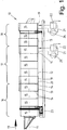
- the in the Fig. 1 The continuous washing machine 10 shown schematically has a cylindrical drum 12 which can be driven in rotation about a preferably horizontal axis of rotation 11.
- the axis of rotation 11 lies on the longitudinal central axis of the drum 12.
- the laundry to be washed is (based on the Fig. 1 ) is transported from left to right in the treatment direction 13 by the rotationally driven drum 12.
- a plurality of successive chambers 15 are formed by transverse partition walls 14 in the treatment direction.
- the chambers 15 may be the same size, but also different sizes.
- the partitions 14 have central or off-center (peripheral) openings which are not shown in the figure. Through the openings, the laundry can be transhipped by line in the treatment direction 13 of a chamber 15 in the subsequent chamber 15.
- the in the Fig. 1 shown continuous washing machine 10 has twelve chambers 15. However, the invention is not limited thereto.
- the continuous washing machine 10 may have a larger or smaller number of chambers 15.
- the first four chambers 15 seen in the treatment direction 13 form a prewashing zone 16 in the continuous washing machine 10 shown.
- the following five chambers 15 form a final wash zone 17 , Clearwash zone 17 and rinse zone 18 may be one of the in the Fig. 1 shown embodiment of the continuous washing machine 10 have different number of chambers 15. It is also conceivable that the rinsing zone 18 at least one further in the Fig. 1 not shown chamber to form a finishing zone follows. Also, the rinse zone 18 may be missing.
- the last chamber 15 of the prewash zone 16, the final wash zone 17 and the rinse zone 18 each have an outer drum 19.
- an outer drum 19 of the first chamber 15 of the final wash zone 17 and the rinse zone 18 is assigned. All outer drums 19 are equally formed liquid impermeable. So that treatment liquid for the laundry in the outer drum 19 with which the respective chamber 15 with an outer drum 19 extending portion of the drum 12 can communicate, the drum 12 in areas of those chambers 15, which is associated with an outer drum 19, at least partially formed permeable to treatment liquid, in particular perforated. As a result, treatment liquid can pass from the respective outer drum 19 into the liquid-permeable section of the drum 12 assigned to the chamber 15, and vice versa.
- the treatment liquid in the respective chamber 15 has a desired level.
- the water level is preferably slightly below the axis of rotation 11 (FIG. Fig. 2 and 3 ). Consequently, the surface of the treatment liquid in the respective chamber 15 is slightly below the axis of rotation 13th
- each of the identically formed outer drums 19 has in the lower region a preferably designed in the manner of a connection box extension.
- This extension receives a supply of the treatment liquid under the drum 12.
- components that are lighter than the treatment liquid for example, foam, lint and the like, collect.
- the lint is preferably at least largely bound in the foam.
- solid components of the treatment liquid may be collected, which are heavier than the treatment liquid.
- the heavier components are dirt washed out of the laundry and other solids, for example small foreign matter, which can pass through the perforation of the drum 12 in the region of the respective chamber 15 with the outer drum 19.
- the outer drum of the last chamber of the final wash zone 17 and the outer drum 19 of the last chamber 15 of the wash zone 18 are each assigned a circulation line 21 with a filter 22. These are the same at the end of the final wash zone 17 and at the end of the rinse zone 18.
- Both the circulation line 21 and the respective filter 22 are located outside the drum 12 and the outer drum 19.
- the respective filter 22 and its associated circulation line 21 are associated with a frame 23 of the continuous washing machine 10, in particular attached thereto.
- the filters 22 may also be located at a different location of the laundry away from the continuous washing machine 10.
- a pump 24 is provided behind the or each filter 22 for pumping back the filtered treatment liquid into the respective outer drum 19.
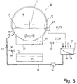
- the shows Fig. 2 in that the circulation line 21 is divided, namely that it is composed of an initial part viewed in the direction of flow to the filter 22 and a return part starting from the filter 22.
- the circulation line 21 is thereby interrupted, wherein the initial part and the return part of the circulation line 21 through the filter 22 but are fluidically connected.
- the initial part of the circulation line 21 is double-stranded, namely has a first initial part 25 and a second initial part 26.
- the first initial part 25 of the circulation line 21 is connected to a drain 27 of the outer drum 19, which is in the range of the level or the surface the treatment liquid in the chamber 15, which is associated with the outer drum 19 is located.
- the second starting part 26 of the circulating line 21 is connected to a second outflow 28 in the bottom area, in particular near the bottom 20, the outer drum 19 of the last chamber 15 of the final wash zone 17.
- the drain 28 may also be provided in the bottom 20 of the outer drum 19. Both starting parts 25 and 26 terminate before the filter 22.
- the return part of the circulation line 21 is assigned to that side of the filter 22 at which the filtered treatment liquid is obtained. By the pump 24 in the return part of the circulation line 21, the filtered liquid is pumped back into the outer drum 19.
- a feed 29 is provided for connecting a rear end of the return part of the circulation line 21 below the surface of the treatment liquid on the outer drum 19.
- the second initial part 26 of the circulation line 21 is assigned a valve 32.
- This is preferably an adjustable throttle valve, whereby the flow rate of the treatment liquid through the second initial part 26 is variable, but also the second starting part 26 can be closed.
- the inflow of treatment liquid from the bottom area of the outer drum 19 to the filter 22 can be completely inhibited or varied with respect to the volume flow of the treatment liquid per unit time to the filter 22, for example, to adjust the capacity of the filter 22.
- the circulation line 21 may be arranged a simple shut-off valve or an adjustable throttle valve.
- valve 33 is located in the return part of the circulation line 21, as seen in the flow direction of the treatment liquid behind the branch of the discharge line 30 from the circulation line 21. Also the discharge line 30 is associated with a valve 34. Through the valves 33 and 34, the outflow of the filtered treatment liquid can be selectively controlled, and selectively back to the outer drum 19 or in the collection tank 31st
- the filter 22 is detailed in FIG Fig. 5 shown.
- This is a so-called gravity filter, in which the treatment liquid to be filtered flows through a filter screen 31 due to gravity, namely from the top of the filter screen 48 to the bottom thereof. This can also take place during the flow of the treatment liquid to be filtered on the filter screen 48.
- the filter screen 48 is arranged in a preferably completely closed housing 35.
- the top of the housing 35 may be open.
- the housing 35 has (seen from the side) over an oblique course with an inclined bottom 36. From above, the ends of the two starting parts 25 and 26 of the circulation line 21 at the highest point in the oblique housing 35 out.
- the filter screen 48 is also mounted obliquely in the housing 35.
- the filter screen 48 thereby divides the housing 35 into a top 37 located above the surface of the filter screen 34 and a bottom 38 located below the filter screen 48.
- the filter screen 48 may be formed of a perforated plate having a uniform pitch of through holes of appropriate size or wire mesh be formed with appropriate mesh size.
- the filter screen 48 is preferably formed in two layers. This filter screen 48 is composed of a lower stable and coarse-meshed support grid and a finely meshed sieve arranged above it, which is formed like a lattice or braided. The optionally flexible screen is then carried by the support grid.
- the filter screen 48 terminates at a distance in front of a transverse wall 39 at the lower end of the housing 35.
- an adjustable in height transverse weir 40 Before the end of the filter screen 37 is an adjustable in height transverse weir 40. By corresponding height adjustment of the plate-like weir 40 is formed above the end of the lint filter 34, a gap corresponding width for the derivation of filtered out of the treatment liquid Ingredients.
- a hinged flap At the location of the height-adjustable weir 40 may also be provided a hinged flap.
- a chamber 42 for collecting the filtered-out from the treatment liquid components.
- a collecting container 43 may be provided for filtered-out components.
- the collecting container 43 is preferably removable from the chamber 42 or drawer-like withdrawn from the chamber 42.
- the housing 35 has a recess in the bottom 36, which forms a sump 44.
- the sump 44 as the lowest point of the housing 35 collects when emptying the filter 22, the remaining filtered treatment liquid.
- the sump 44 forms a pump template, which ensures that during operation of the filter 22, the pump 24 is always supplied with sufficiently filtered treatment liquid.
- a float switch 45 is also provided, which serves to prevent dry running of the pump 24.
- a closable drain 46 is located at the lowest point of the sump 44. When the drain 46 is open, the treatment liquid can be completely drained from the housing 35 of the filter 22.
- a plurality of directed against the underside of the filter screen 48 Abalismsdüsen 47 are provided in the lower part 38 of the housing 35 .
- the cleaning nozzles 47 are arranged distributed in the lower part 38 so that they can apply all or at least a majority of the underside of the filter screen 48 with cleaning liquid.
- the cleaning liquid is preferably fresh water. However, it is also possible to use filtered treatment liquid from the collection tank 31. The used cleaning liquid is then pumped back through the return part of the circulation line 21 and the discharge line 30 into the collection tank 31 or into a drain.
- the flow rate of the treatment liquid through the circulation line 21 is selected or adjusted at the throttle valve 32, that in the course of a treatment process of the laundry item in the respective chamber 15, the treatment liquid in this chamber 15 at least once completely rolled and filtered by the filter 22.
- the inventive method is designed so that it allows a multiple function of the filter 22.
- the filter 22 is thus used to fulfill different filtering tasks, which are schematically illustrated in FIGS Fig. 2 to 4 are shown.
- the Fig. 2 shows the use of the filter 22 for removing such components from the treatment liquid, which are lighter than the treatment liquid, for example foam, especially foam along with entrained fluff.
- the foam optionally with the fluff, collects on the surface 49 of the treatment liquid in the drum 12.
- the outflow 27 which is located in the region of the surface 49 of the treatment liquid, the foam with lint and other lighter constituents together with it on the surface 49 befindaji treatment liquid withdrawn from the drum 12 and the outer drum 19 via the drain 27 and placed over the first initial part 25 of the circulation line 21 to the filter 22.
- the treatment liquid with the lighter components passes into the upper part 37 of the housing 35 of the filter 22.
- the treatment liquid to be filtered flows with the lighter components to be filtered out on the filter screen 48.
- the filtered treatment liquid is then pumped through the pump 24 Circulation line 21 is pumped with the valve open 33 to the inlet 29 in the outer drum 19 and thus the filtered treatment liquid the washing process, namely the outer drum 19 and the drum 12, fed again.
- the filtered lighter components of the treatment liquid flow on the inclined filter 48. Through the gap under the transverse edge 41 of the weir 40 reach these filtered lighter components, in particular foam and lint, in the sump 43 of the filter 22. In the collecting 43 accumulate in particular lint, which can be disposed of from time to time by pulling or removing the Collecting container 43 from the chamber 42 of the housing 35 of the filter 22. Other components may collect at another location of the chamber 42 and be discharged therefrom, for example, in an outflow.
- the valves 32 and 34 are closed. Then, only light components are separated from the treatment liquid and the filtered treatment liquid in the circulation through the circulation line 21 is continuously pumped back into the continuous washing machine 10. Thus, the treatment liquid is continuously recycled treated treatment liquid again, so that the amount of treatment liquid in the respective chamber 15 substantially always remains the same and is reduced only to the located in the circulation line 21 and in the region of the filter 22 treatment liquid.
- the foam carpet on the treatment liquid is reduced, thereby enhancing the washing effect, whereby, in particular, stains can be more effectively removed from the laundry.
- the Fig. 3 schematically illustrates a second application of the filter 22.
- the valve 32 in the second initial part 26 of the circulation line 21 is so wide open or adjusted so that the treatment liquid is continuously fed to the filter 22 during the washing of the laundry.
- the preferably designed as a throttle valve 32 is set so that only a desired volume flow of the treatment liquid flows through the circulation line 21.
- the treatment liquid comes through the arranged close to the bottom 20 of the outer drum 19 drain 28 in the second initial part 26 a.
- the treatment liquid heavier components of the same, for example, removed from the laundry dirt particles, but also other small solid particles and possibly foreign body, via the drain 28 and the second initial part 26 of the circulation line 21 to the filter 22.
- the first starting part 25 of the circulation line 21 can be shut off in the embodiment shown by no valve. Therefore, on the surface 49 of the treatment liquid floating components are constantly passed through the first initial part 25 of the circulation line 21 to the filter 22.
- the second initial part 26 of the circulation line 21 flows through the second initial part 26 of the circulation line 21 as a result of this associated lockable and throttle valve 32 only treatment liquid with heavier components contained therein, if that is desired.
- the valve 32 may only be opened periodically during the wash.
- the valve 32 can also be constantly open, whereby only as much treatment liquid is guided through the throttle through the second initial part 26 to the filter 22, as the filter capacity permits. It is also conceivable, however, also to associate a valve with the first starting part 25 of the circulation line 21. When this is closed, with the valve 25 open in the second starting part 26, only treatment liquid with heavier constituents contained therein can be fed to the filter 22 and from this the treatment liquid can be freed of heavy constituents.
- the Fig. 4 shows the method according to a third operation of the filter 22.
- a bath change so an exchange of the treatment liquid, is carried out in the respective chamber 15.
- Such a bath change preferably takes place after washing the items of laundry in the relevant chamber 15, when the item of laundry is reloaded from the chamber 15 into the next in the treatment direction 13 chamber 15, for example, the first Chamber 15 of the rinsing zone 18, or to unload the fully washed and rinsed Wäschepostens from the continuous washing machine 10th
- the valve 32 in the second initial part 26 of the circulation line 21 and a possible valve in the first initial part 25 are preferably fully open.
- the treatment liquid can then be completely discharged from the drum 12 and its associated outer drum 19.
- the treatment liquid to be discharged is filtered, and then the filtered treatment liquid is passed from the pump 24 through the circulation line 21 with the valve 34 open in the discharge line 30 into the collecting tank 31.
- the following in the direction of flow of the treatment liquid through the circulation line 21 to the discharge line 30 valve 33 in the circulation line 21 is then preferably closed.
- the lower sump 44 in the housing 35 of the filter 22 makes it possible to discharge the treatment liquid completely from the filter 22 through the drain 46.
- the drain 46 leaves only the bottom of the sump 44 collecting residual treatment liquid not from the pump 24 in the Collection tank 31 can be pumped.
- mixing of the treatment liquid of the washing process last taken with optionally other treatment liquid for the next washing operation is avoided.
- the treatment liquid from the drum 12 and the outer drum 19 is completely drained, it is preferably carried out at the moment no filtering Deutschenmixdem filter 22, a cleaning of the filter screen 48. This is done from the bottom of the filter 48 through the directed to this Abalismsdüsen 47.
- the cleaning nozzles 47 can to be supplied with fresh water or purified treatment liquid from the collection tank 31 as a cleaning liquid.
- the contaminated cleaning liquid accumulating during cleaning of the filter screen 48 is discharged below the filter screen 48, that is to say in the lower part 38.
- the cleaning liquid collects in the sump 44 at the lowest point of the housing 35 of the filter 22 and is completely drained from here through the drain 46 and then disposed of.
- the cleaning of the filter 22 can also be done to in the operation of the filter 22 according to the Fig. 2 to destroy or reduce the amount of foam.
- the method works both in the last chamber 15 of the final wash zone 17 and the last chamber 15 of the rinse zone 18th
- 16 can be moved to the last chamber 15 of the prewash zone as well.
- the method described above is also suitable for continuous washing machines which have only one pre-wash zone 16 and one final wash zone 17, but no rinse zone 18.
- the invention is not only suitable for continuous washing machines of all kinds, but also for other washing machines and washing machines for washing or cleaning any other objects, so not only laundry.
Claims (12)
- Procédé de lavage, en particulier de pièces de linge, dans lequel les pièces de linge sont au moins lavées avec un liquide de traitement dans un tambour (12) pouvant être entraîné en rotation, on évacue au besoin le liquide de traitement hors du tambour (12) au moyen d'au moins un tambour extérieur (19) associé à au moins une partie du tambour (12) et on filtre pendant au moins le lavage le liquide de traitement à l'extérieur du tambour (12) et dudit au moins un tambour extérieur (19), caractérisé en ce que l'on filtre au choix ou en alternance hors du liquide de traitement des composants qui sont plus légers ou plus lourds que le liquide de traitement, dans lequel, pour le filtrage de composants plus légers du liquide de traitement, on prélève le liquide de traitement avec les composants plus légers à sa surface hors du tambour extérieur (19) et, pour le filtrage de composants plus lourds du liquide de traitement, on prélève le liquide de traitement avec les composants plus lourds en dessous de la surface du liquide de traitement hors de celui-ci.
- Procédé selon la revendication 1, caractérisé en ce que l'on effectue le filtrage en continu pendant au moins une partie de la durée du processus de lavage, de préférence du fait que l'on ne pompe toujours qu'une partie du liquide de traitement successivement dans le circuit à travers ou via un filtre (22).
- Procédé selon la revendication 1 ou 2, caractérisé en ce que l'on ne filtre toujours qu'une partie, de préférence une partie relativement petite, du liquide de traitement.
- Procédé selon l'une quelconque des revendications 1 à 3, caractérisé en ce que l'on soutire en continu à au moins une évacuation (27, 28) un peu de liquide de traitement hors du tambour extérieur respectif (19) et on renvoie ce liquide de traitement immédiatement après le filtrage dans le même tambour extérieur (19).
- Procédé selon l'une quelconque des revendications précédentes, caractérisé en ce que l'on conduit du liquide de traitement à évacuer hors d'au moins un tambour extérieur (19), de préférence à la fin du traitement respectif des pièces de linge, à travers ou via le même filtre (22), dans lequel on évacue de préférence le liquide de traitement filtré dans au moins un réservoir de collecte (31).
- Procédé selon l'une quelconque des revendications précédentes, caractérisé en ce que l'on filtre le liquide de traitement avec un filtre (22) réalisé en forme de filtre gravitaire et/ou on verse le liquide de traitement en écoulement libre sur le filtre (22) sous l'effet de la gravité.
- Dispositif de lavage en particulier de pièces de linge, avec un tambour (12) pouvant être entraîné en rotation et au moins un tambour extérieur fixe (19), qui s'étend au moins sur une partie de la longueur du tambour et auquel au moins une conduite de dérivation (21) avec au moins un filtre (22) est associée, caractérisé en ce que plusieurs évacuations (27, 28) pour le liquide de traitement, dont au moins une partie peuvent être fermées, sont associées à la conduite de dérivation (21), et une évacuation supérieure est disposée dans la région du niveau ou de la surface (49) du liquide de traitement dans le tambour (12) et dans le tambour extérieur (19), tandis qu'une autre évacuation (28) est prévue dans le fond (20) ou dans la région du fond (20) du tambour extérieur respectif (19).
- Dispositif selon la revendication 7, caractérisé en ce qu'il est prévu au moins une pompe (24) dans la conduite de dérivation (21), de préférence après ledit au moins un filtre (22), en considérant la direction d'écoulement du liquide de traitement à travers la conduite de dérivation (21).
- Dispositif selon la revendication 7 ou 8, caractérisé en ce que la conduite de dérivation (21) est raccordée, de préférence après la pompe (24), à un accès (29), pouvant en particulier être fermé, vers le tambour extérieur respectif (19) pour le renvoi du liquide de traitement filtré dans le même tambour extérieur (19), duquel le liquide de refroidissement a été prélevé pour le filtrage.
- Dispositif selon l'une quelconque des revendications 7 à 9, caractérisé en ce que la conduite de dérivation (21) présente une conduite de décharge (30), à laquelle est de préférence associé au moins un réservoir de collecte (31).
- Dispositif selon l'une quelconque des revendications 7 à 10, caractérisé en ce que ledit au moins un filtre (22) est réalisé en forme de filtre gravitaire.
- Dispositif selon l'une quelconque des revendications 7 à 11, caractérisé en ce que le tambour (12) est réalisé en forme de tambour cylindrique allongé, avec plusieurs chambres successives (15), dans lequel un tambour extérieur (19) est associé à au moins une des chambres (15).
Applications Claiming Priority (1)
| Application Number | Priority Date | Filing Date | Title |
|---|---|---|---|
| DE102011013806A DE102011013806A1 (de) | 2011-03-14 | 2011-03-14 | Verfahren und Vorrichtung zum Waschen von insbesondere Wäschestücken |
Publications (3)
| Publication Number | Publication Date |
|---|---|
| EP2500459A1 EP2500459A1 (fr) | 2012-09-19 |
| EP2500459B1 true EP2500459B1 (fr) | 2017-09-20 |
| EP2500459B2 EP2500459B2 (fr) | 2021-04-14 |
Family
ID=45811242
Family Applications (1)
| Application Number | Title | Priority Date | Filing Date |
|---|---|---|---|
| EP12001271.1A Active EP2500459B2 (fr) | 2011-03-14 | 2012-02-27 | Procédé et dispositif de lavage, en particulier de pièces de linge |
Country Status (3)
| Country | Link |
|---|---|
| US (1) | US20120233785A1 (fr) |
| EP (1) | EP2500459B2 (fr) |
| DE (1) | DE102011013806A1 (fr) |
Families Citing this family (4)
| Publication number | Priority date | Publication date | Assignee | Title |
|---|---|---|---|---|
| CN111875130A (zh) * | 2013-03-20 | 2020-11-03 | 海德系统Ip有限公司 | 水处理系统 |
| CN105793482A (zh) * | 2013-12-17 | 2016-07-20 | 佩莱若林·米尔诺公司 | 地毯和载有微粒的材料的洗涤装置及方法 |
| CN107475987A (zh) * | 2017-10-10 | 2017-12-15 | 无锡市南长实验中学 | 一种家用洗衣机 |
| CN109505102B (zh) * | 2018-11-01 | 2022-08-09 | 佛山海尔滚筒洗衣机有限公司 | 一种带有除泡沫装置的洗衣机 |
Citations (3)
| Publication number | Priority date | Publication date | Assignee | Title |
|---|---|---|---|---|
| US3734854A (en) | 1971-12-29 | 1973-05-22 | J Altadonna | Liquid processing system |
| US6167733B1 (en) | 1998-06-30 | 2001-01-02 | Daewoo Electronics Co., Ltd. | Drum type washing machine having a pump integrally formed with a filter |
| US20050120758A1 (en) | 2002-05-08 | 2005-06-09 | Thies Edward L. | Remote sump with film heater and auto purge |
Family Cites Families (3)
| Publication number | Priority date | Publication date | Assignee | Title |
|---|---|---|---|---|
| NZ223338A (en) * | 1987-04-24 | 1991-01-29 | Ecolab Inc | Automatic neutralisation of oxidising agent in a laundry bath |
| JP2005043690A (ja) * | 2003-07-23 | 2005-02-17 | Fujinon Corp | プラスチックレンズの保持方法およびプラスチックレンズの保持構造 |
| US20050183208A1 (en) * | 2004-02-20 | 2005-08-25 | The Procter & Gamble Company | Dual mode laundry apparatus and method using the same |
-
2011
- 2011-03-14 DE DE102011013806A patent/DE102011013806A1/de not_active Withdrawn
-
2012
- 2012-02-27 EP EP12001271.1A patent/EP2500459B2/fr active Active
- 2012-03-14 US US13/419,528 patent/US20120233785A1/en not_active Abandoned
Patent Citations (3)
| Publication number | Priority date | Publication date | Assignee | Title |
|---|---|---|---|---|
| US3734854A (en) | 1971-12-29 | 1973-05-22 | J Altadonna | Liquid processing system |
| US6167733B1 (en) | 1998-06-30 | 2001-01-02 | Daewoo Electronics Co., Ltd. | Drum type washing machine having a pump integrally formed with a filter |
| US20050120758A1 (en) | 2002-05-08 | 2005-06-09 | Thies Edward L. | Remote sump with film heater and auto purge |
Non-Patent Citations (10)
| Title |
|---|
| "Offenkundige Vorbenutzung durch eine Taktwaschanlage der Einsprechenden vom Typ ?P50-16", MEWA - TEXTIL-MIETSERVICE, January 1999 (1999-01-01), Graz, Österreich |
| "Offenkundige Vorbenutzung durch eine Taktwaschanlage der Einsprechenden vom Typ ?P50-18", FLIEGEL TEXTILSERVICE, January 2010 (2010-01-01), Czarnowo, Polen |
| FINALES FUNKTIONSSCHEMA DER AUSGELIEFERTEN ANLAGE ?P50-16, 21 January 1999 (1999-01-21) |
| FOTO DER ANLAGE ?P50-18 |
| FUNKTIONSSCHEMA DER ANLAGE ?P50-16'' FÜR ANGEBOT, 26 October 1998 (1998-10-26) |
| FUNKTIONSSCHEMA DER ANLAGE ?P50-18, 16 March 2010 (2010-03-16) |
| GEGENSTROMFILTER 3-FACH IN DOPPELAUSFÜHRUNG, 11 September 1986 (1986-09-11) |
| GEGENSTROMFILTER GR. 3, 25 April 1997 (1997-04-25), pages 36 - 4107 |
| INTERNE KOMPONENTENLISTE FÜR AUFTRAG 1049287, 11 December 1998 (1998-12-11) |
| NACHRÜSTUNG BOGENSIEB UND SCHAUMÜBERLÄUFE FÜR BEREITS EXISTIERENDE WASCHANLAGE VOM TYP ?P50-18, 23 February 2010 (2010-02-23) |
Also Published As
| Publication number | Publication date |
|---|---|
| DE102011013806A1 (de) | 2012-09-20 |
| EP2500459B2 (fr) | 2021-04-14 |
| US20120233785A1 (en) | 2012-09-20 |
| EP2500459A1 (fr) | 2012-09-19 |
Similar Documents
| Publication | Publication Date | Title |
|---|---|---|
| EP2252191B1 (fr) | Procédé d'auto-nettoyage d'un lave-vaisselle à avancement automatique et lave-vaisselle à avancement automatique correspondant | |
| DE102009048810B4 (de) | Spülmaschine mit Schmutzaustragsystem | |
| EP0838190A2 (fr) | Machine à laver la vaisselle type tunnel et procédé pour nettoyer la vaisselle et/ou les plateaux | |
| DE2733576A1 (de) | Filterspuelvorrichtung fuer geschirrspuelmaschinen | |
| DE102019205919B4 (de) | Wasserführendes Haushaltsgerät und Verfahren zu seinem Betrieb | |
| DE2741871C2 (de) | Vorrichtung zum Waschen von Gemüse, Salat oder dgl. | |
| DE102019203809B3 (de) | Wasserführendes Haushaltsgerät und Verfahren zu seinem Betrieb | |
| DE2938439A1 (de) | Verfahren und vorrichtung zur feldreinigung von rodungsfruechten | |
| EP2117408B1 (fr) | Filtre pour des machines à laver | |
| EP2500459B1 (fr) | Procédé et dispositif de lavage, en particulier de pièces de linge | |
| DE60034659T2 (de) | Filtervorrichtung mit sandfilterbett | |
| DE102011017294A1 (de) | Transportspülmaschine mit Sonderbehandlungszonen | |
| DE102010063711A1 (de) | Spülmaschine mit automatischer Schmutzaustragung | |
| WO2020078705A2 (fr) | Lave-vaisselle ménager pourvu d'un système de filtre autonettoyant | |
| DE3842640C2 (de) | Geschirrspülmaschine | |
| DE1428411B2 (de) | Schmutzabscheider in einer Geschirrspülmaschine | |
| DE4038305C1 (en) | Treating waste water from vehicle washing plant - in which water is collected from each washing zone and supplied to at least two=stage treatment plant | |
| DE69906521T2 (de) | Verfahren und vorrichtung in einer trockenreinigungsmaschine | |
| DE10331998A1 (de) | Vorrichtung zum Filtern von verunreinigten Flüssigkeiten, wie Kühlschmiermittel, insbesondere aus Werkzeugmaschinen | |
| DE69637101T2 (de) | Filter mit drehbarer Trommel und und dessen Verwendung zum filtrieren eines Fluids | |
| DE202004017681U1 (de) | Gemüsewaschanlage mit Fächern | |
| DE3938544A1 (de) | Verfahren und vorrichtung zum trennen insbesondere oelverschmutzter abfallteile aus stahl oder blech und papier | |
| DE102015012354B4 (de) | Vorrichtung zum Waschen von kleinstückigem Material | |
| DE10031038B4 (de) | Verfahren zum Abscheiden von Verunreinigungen aus einer Flüssigkeit zum Waschen von Wäsche in einer Durchlaufwaschmaschine | |
| DE102008040997A1 (de) | Mobile Reinigungsanlage sowie Verfahren zum Betreiben einer mobilen Reinigungsanlage |
Legal Events
| Date | Code | Title | Description |
|---|---|---|---|
| PUAI | Public reference made under article 153(3) epc to a published international application that has entered the european phase |
Free format text: ORIGINAL CODE: 0009012 |
|
| AK | Designated contracting states |
Kind code of ref document: A1 Designated state(s): AL AT BE BG CH CY CZ DE DK EE ES FI FR GB GR HR HU IE IS IT LI LT LU LV MC MK MT NL NO PL PT RO RS SE SI SK SM TR |
|
| AX | Request for extension of the european patent |
Extension state: BA ME |
|
| RIN1 | Information on inventor provided before grant (corrected) |
Inventor name: HEINZ, ENGELBERT Inventor name: BRINGEWATT, WILHELM |
|
| 17P | Request for examination filed |
Effective date: 20130319 |
|
| GRAP | Despatch of communication of intention to grant a patent |
Free format text: ORIGINAL CODE: EPIDOSNIGR1 |
|
| INTG | Intention to grant announced |
Effective date: 20170420 |
|
| GRAS | Grant fee paid |
Free format text: ORIGINAL CODE: EPIDOSNIGR3 |
|
| GRAA | (expected) grant |
Free format text: ORIGINAL CODE: 0009210 |
|
| STAA | Information on the status of an ep patent application or granted ep patent |
Free format text: STATUS: THE PATENT HAS BEEN GRANTED |
|
| AK | Designated contracting states |
Kind code of ref document: B1 Designated state(s): AL AT BE BG CH CY CZ DE DK EE ES FI FR GB GR HR HU IE IS IT LI LT LU LV MC MK MT NL NO PL PT RO RS SE SI SK SM TR |
|
| REG | Reference to a national code |
Ref country code: GB Ref legal event code: FG4D Free format text: NOT ENGLISH |
|
| REG | Reference to a national code |
Ref country code: CH Ref legal event code: EP |
|
| REG | Reference to a national code |
Ref country code: AT Ref legal event code: REF Ref document number: 930189 Country of ref document: AT Kind code of ref document: T Effective date: 20171015 |
|
| REG | Reference to a national code |
Ref country code: IE Ref legal event code: FG4D Free format text: LANGUAGE OF EP DOCUMENT: GERMAN |
|
| REG | Reference to a national code |
Ref country code: DE Ref legal event code: R096 Ref document number: 502012011290 Country of ref document: DE |
|
| REG | Reference to a national code |
Ref country code: NL Ref legal event code: MP Effective date: 20170920 |
|
| REG | Reference to a national code |
Ref country code: FR Ref legal event code: PLFP Year of fee payment: 7 |
|
| PG25 | Lapsed in a contracting state [announced via postgrant information from national office to epo] |
Ref country code: FI Free format text: LAPSE BECAUSE OF FAILURE TO SUBMIT A TRANSLATION OF THE DESCRIPTION OR TO PAY THE FEE WITHIN THE PRESCRIBED TIME-LIMIT Effective date: 20170920 Ref country code: SE Free format text: LAPSE BECAUSE OF FAILURE TO SUBMIT A TRANSLATION OF THE DESCRIPTION OR TO PAY THE FEE WITHIN THE PRESCRIBED TIME-LIMIT Effective date: 20170920 Ref country code: HR Free format text: LAPSE BECAUSE OF FAILURE TO SUBMIT A TRANSLATION OF THE DESCRIPTION OR TO PAY THE FEE WITHIN THE PRESCRIBED TIME-LIMIT Effective date: 20170920 Ref country code: NO Free format text: LAPSE BECAUSE OF FAILURE TO SUBMIT A TRANSLATION OF THE DESCRIPTION OR TO PAY THE FEE WITHIN THE PRESCRIBED TIME-LIMIT Effective date: 20171220 Ref country code: LT Free format text: LAPSE BECAUSE OF FAILURE TO SUBMIT A TRANSLATION OF THE DESCRIPTION OR TO PAY THE FEE WITHIN THE PRESCRIBED TIME-LIMIT Effective date: 20170920 |
|
| REG | Reference to a national code |
Ref country code: LT Ref legal event code: MG4D |
|
| PG25 | Lapsed in a contracting state [announced via postgrant information from national office to epo] |
Ref country code: RS Free format text: LAPSE BECAUSE OF FAILURE TO SUBMIT A TRANSLATION OF THE DESCRIPTION OR TO PAY THE FEE WITHIN THE PRESCRIBED TIME-LIMIT Effective date: 20170920 Ref country code: BG Free format text: LAPSE BECAUSE OF FAILURE TO SUBMIT A TRANSLATION OF THE DESCRIPTION OR TO PAY THE FEE WITHIN THE PRESCRIBED TIME-LIMIT Effective date: 20171220 Ref country code: LV Free format text: LAPSE BECAUSE OF FAILURE TO SUBMIT A TRANSLATION OF THE DESCRIPTION OR TO PAY THE FEE WITHIN THE PRESCRIBED TIME-LIMIT Effective date: 20170920 Ref country code: GR Free format text: LAPSE BECAUSE OF FAILURE TO SUBMIT A TRANSLATION OF THE DESCRIPTION OR TO PAY THE FEE WITHIN THE PRESCRIBED TIME-LIMIT Effective date: 20171221 |
|
| PG25 | Lapsed in a contracting state [announced via postgrant information from national office to epo] |
Ref country code: NL Free format text: LAPSE BECAUSE OF FAILURE TO SUBMIT A TRANSLATION OF THE DESCRIPTION OR TO PAY THE FEE WITHIN THE PRESCRIBED TIME-LIMIT Effective date: 20170920 |
|
| PG25 | Lapsed in a contracting state [announced via postgrant information from national office to epo] |
Ref country code: RO Free format text: LAPSE BECAUSE OF FAILURE TO SUBMIT A TRANSLATION OF THE DESCRIPTION OR TO PAY THE FEE WITHIN THE PRESCRIBED TIME-LIMIT Effective date: 20170920 Ref country code: PL Free format text: LAPSE BECAUSE OF FAILURE TO SUBMIT A TRANSLATION OF THE DESCRIPTION OR TO PAY THE FEE WITHIN THE PRESCRIBED TIME-LIMIT Effective date: 20170920 Ref country code: ES Free format text: LAPSE BECAUSE OF FAILURE TO SUBMIT A TRANSLATION OF THE DESCRIPTION OR TO PAY THE FEE WITHIN THE PRESCRIBED TIME-LIMIT Effective date: 20170920 Ref country code: CZ Free format text: LAPSE BECAUSE OF FAILURE TO SUBMIT A TRANSLATION OF THE DESCRIPTION OR TO PAY THE FEE WITHIN THE PRESCRIBED TIME-LIMIT Effective date: 20170920 |
|
| PG25 | Lapsed in a contracting state [announced via postgrant information from national office to epo] |
Ref country code: IS Free format text: LAPSE BECAUSE OF FAILURE TO SUBMIT A TRANSLATION OF THE DESCRIPTION OR TO PAY THE FEE WITHIN THE PRESCRIBED TIME-LIMIT Effective date: 20180120 Ref country code: SK Free format text: LAPSE BECAUSE OF FAILURE TO SUBMIT A TRANSLATION OF THE DESCRIPTION OR TO PAY THE FEE WITHIN THE PRESCRIBED TIME-LIMIT Effective date: 20170920 Ref country code: EE Free format text: LAPSE BECAUSE OF FAILURE TO SUBMIT A TRANSLATION OF THE DESCRIPTION OR TO PAY THE FEE WITHIN THE PRESCRIBED TIME-LIMIT Effective date: 20170920 Ref country code: SM Free format text: LAPSE BECAUSE OF FAILURE TO SUBMIT A TRANSLATION OF THE DESCRIPTION OR TO PAY THE FEE WITHIN THE PRESCRIBED TIME-LIMIT Effective date: 20170920 Ref country code: IT Free format text: LAPSE BECAUSE OF FAILURE TO SUBMIT A TRANSLATION OF THE DESCRIPTION OR TO PAY THE FEE WITHIN THE PRESCRIBED TIME-LIMIT Effective date: 20170920 |
|
| REG | Reference to a national code |
Ref country code: DE Ref legal event code: R026 Ref document number: 502012011290 Country of ref document: DE |
|
| PLBI | Opposition filed |
Free format text: ORIGINAL CODE: 0009260 |
|
| PLAX | Notice of opposition and request to file observation + time limit sent |
Free format text: ORIGINAL CODE: EPIDOSNOBS2 |
|
| PG25 | Lapsed in a contracting state [announced via postgrant information from national office to epo] |
Ref country code: DK Free format text: LAPSE BECAUSE OF FAILURE TO SUBMIT A TRANSLATION OF THE DESCRIPTION OR TO PAY THE FEE WITHIN THE PRESCRIBED TIME-LIMIT Effective date: 20170920 |
|
| 26 | Opposition filed |
Opponent name: JENSEN GMBH Effective date: 20180620 |
|
| REG | Reference to a national code |
Ref country code: CH Ref legal event code: PL |
|
| PG25 | Lapsed in a contracting state [announced via postgrant information from national office to epo] |
Ref country code: MT Free format text: LAPSE BECAUSE OF FAILURE TO SUBMIT A TRANSLATION OF THE DESCRIPTION OR TO PAY THE FEE WITHIN THE PRESCRIBED TIME-LIMIT Effective date: 20170920 Ref country code: MC Free format text: LAPSE BECAUSE OF FAILURE TO SUBMIT A TRANSLATION OF THE DESCRIPTION OR TO PAY THE FEE WITHIN THE PRESCRIBED TIME-LIMIT Effective date: 20170920 |
|
| GBPC | Gb: european patent ceased through non-payment of renewal fee |
Effective date: 20180227 |
|
| PLBB | Reply of patent proprietor to notice(s) of opposition received |
Free format text: ORIGINAL CODE: EPIDOSNOBS3 |
|
| REG | Reference to a national code |
Ref country code: IE Ref legal event code: MM4A |
|
| PG25 | Lapsed in a contracting state [announced via postgrant information from national office to epo] |
Ref country code: SI Free format text: LAPSE BECAUSE OF FAILURE TO SUBMIT A TRANSLATION OF THE DESCRIPTION OR TO PAY THE FEE WITHIN THE PRESCRIBED TIME-LIMIT Effective date: 20170920 Ref country code: LI Free format text: LAPSE BECAUSE OF NON-PAYMENT OF DUE FEES Effective date: 20180228 Ref country code: CH Free format text: LAPSE BECAUSE OF NON-PAYMENT OF DUE FEES Effective date: 20180228 Ref country code: LU Free format text: LAPSE BECAUSE OF NON-PAYMENT OF DUE FEES Effective date: 20180227 |
|
| PG25 | Lapsed in a contracting state [announced via postgrant information from national office to epo] |
Ref country code: IE Free format text: LAPSE BECAUSE OF NON-PAYMENT OF DUE FEES Effective date: 20180227 |
|
| PG25 | Lapsed in a contracting state [announced via postgrant information from national office to epo] |
Ref country code: GB Free format text: LAPSE BECAUSE OF NON-PAYMENT OF DUE FEES Effective date: 20180227 |
|
| REG | Reference to a national code |
Ref country code: AT Ref legal event code: MM01 Ref document number: 930189 Country of ref document: AT Kind code of ref document: T Effective date: 20180227 |
|
| PG25 | Lapsed in a contracting state [announced via postgrant information from national office to epo] |
Ref country code: AT Free format text: LAPSE BECAUSE OF NON-PAYMENT OF DUE FEES Effective date: 20180227 |
|
| REG | Reference to a national code |
Ref country code: DE Ref legal event code: R079 Ref document number: 502012011290 Country of ref document: DE Free format text: PREVIOUS MAIN CLASS: D06F0033020000 Ipc: D06F0033300000 |
|
| PLBP | Opposition withdrawn |
Free format text: ORIGINAL CODE: 0009264 |
|
| PG25 | Lapsed in a contracting state [announced via postgrant information from national office to epo] |
Ref country code: TR Free format text: LAPSE BECAUSE OF FAILURE TO SUBMIT A TRANSLATION OF THE DESCRIPTION OR TO PAY THE FEE WITHIN THE PRESCRIBED TIME-LIMIT Effective date: 20170920 |
|
| PG25 | Lapsed in a contracting state [announced via postgrant information from national office to epo] |
Ref country code: PT Free format text: LAPSE BECAUSE OF FAILURE TO SUBMIT A TRANSLATION OF THE DESCRIPTION OR TO PAY THE FEE WITHIN THE PRESCRIBED TIME-LIMIT Effective date: 20170920 Ref country code: HU Free format text: LAPSE BECAUSE OF FAILURE TO SUBMIT A TRANSLATION OF THE DESCRIPTION OR TO PAY THE FEE WITHIN THE PRESCRIBED TIME-LIMIT; INVALID AB INITIO Effective date: 20120227 |
|
| PG25 | Lapsed in a contracting state [announced via postgrant information from national office to epo] |
Ref country code: CY Free format text: LAPSE BECAUSE OF FAILURE TO SUBMIT A TRANSLATION OF THE DESCRIPTION OR TO PAY THE FEE WITHIN THE PRESCRIBED TIME-LIMIT Effective date: 20170920 Ref country code: MK Free format text: LAPSE BECAUSE OF NON-PAYMENT OF DUE FEES Effective date: 20170920 |
|
| PG25 | Lapsed in a contracting state [announced via postgrant information from national office to epo] |
Ref country code: AL Free format text: LAPSE BECAUSE OF FAILURE TO SUBMIT A TRANSLATION OF THE DESCRIPTION OR TO PAY THE FEE WITHIN THE PRESCRIBED TIME-LIMIT Effective date: 20170920 |
|
| PUAH | Patent maintained in amended form |
Free format text: ORIGINAL CODE: 0009272 |
|
| STAA | Information on the status of an ep patent application or granted ep patent |
Free format text: STATUS: PATENT MAINTAINED AS AMENDED |
|
| 27A | Patent maintained in amended form |
Effective date: 20210414 |
|
| AK | Designated contracting states |
Kind code of ref document: B2 Designated state(s): AL AT BE BG CH CY CZ DE DK EE ES FI FR GB GR HR HU IE IS IT LI LT LU LV MC MK MT NL NO PL PT RO RS SE SI SK SM TR |
|
| REG | Reference to a national code |
Ref country code: DE Ref legal event code: R102 Ref document number: 502012011290 Country of ref document: DE |
|
| PGFP | Annual fee paid to national office [announced via postgrant information from national office to epo] |
Ref country code: FR Payment date: 20230221 Year of fee payment: 12 |
|
| PGFP | Annual fee paid to national office [announced via postgrant information from national office to epo] |
Ref country code: DE Payment date: 20230330 Year of fee payment: 12 Ref country code: BE Payment date: 20230224 Year of fee payment: 12 |
|
| P01 | Opt-out of the competence of the unified patent court (upc) registered |
Effective date: 20230529 |