EP2500459B1 - Method and device for washing, in particular laundry items - Google Patents
Method and device for washing, in particular laundry items Download PDFInfo
- Publication number
- EP2500459B1 EP2500459B1 EP12001271.1A EP12001271A EP2500459B1 EP 2500459 B1 EP2500459 B1 EP 2500459B1 EP 12001271 A EP12001271 A EP 12001271A EP 2500459 B1 EP2500459 B1 EP 2500459B1
- Authority
- EP
- European Patent Office
- Prior art keywords
- treatment liquid
- filter
- drum
- outer drum
- filtered
- Prior art date
- Legal status (The legal status is an assumption and is not a legal conclusion. Google has not performed a legal analysis and makes no representation as to the accuracy of the status listed.)
- Active
Links
Images


Classifications
-
- D—TEXTILES; PAPER
- D06—TREATMENT OF TEXTILES OR THE LIKE; LAUNDERING; FLEXIBLE MATERIALS NOT OTHERWISE PROVIDED FOR
- D06F—LAUNDERING, DRYING, IRONING, PRESSING OR FOLDING TEXTILE ARTICLES
- D06F39/00—Details of washing machines not specific to a single type of machines covered by groups D06F9/00 - D06F27/00
- D06F39/10—Filtering arrangements
-
- D—TEXTILES; PAPER
- D06—TREATMENT OF TEXTILES OR THE LIKE; LAUNDERING; FLEXIBLE MATERIALS NOT OTHERWISE PROVIDED FOR
- D06F—LAUNDERING, DRYING, IRONING, PRESSING OR FOLDING TEXTILE ARTICLES
- D06F31/00—Washing installations comprising an assembly of several washing machines or washing units, e.g. continuous flow assemblies
- D06F31/005—Washing installations comprising an assembly of several washing machines or washing units, e.g. continuous flow assemblies consisting of one or more rotating drums through which the laundry passes in a continuous flow
-
- D—TEXTILES; PAPER
- D06—TREATMENT OF TEXTILES OR THE LIKE; LAUNDERING; FLEXIBLE MATERIALS NOT OTHERWISE PROVIDED FOR
- D06F—LAUNDERING, DRYING, IRONING, PRESSING OR FOLDING TEXTILE ARTICLES
- D06F35/00—Washing machines, apparatus, or methods not otherwise provided for
- D06F35/005—Methods for washing, rinsing or spin-drying
- D06F35/006—Methods for washing, rinsing or spin-drying for washing or rinsing only
-
- D—TEXTILES; PAPER
- D06—TREATMENT OF TEXTILES OR THE LIKE; LAUNDERING; FLEXIBLE MATERIALS NOT OTHERWISE PROVIDED FOR
- D06F—LAUNDERING, DRYING, IRONING, PRESSING OR FOLDING TEXTILE ARTICLES
- D06F39/00—Details of washing machines not specific to a single type of machines covered by groups D06F9/00 - D06F27/00
- D06F39/08—Liquid supply or discharge arrangements
- D06F39/083—Liquid discharge or recirculation arrangements
Definitions
- the invention relates to a method for washing in particular items of laundry according to the preamble of claim 1. Furthermore, the invention relates to a device for washing laundry in particular according to the preamble of claim 7 (see US-A-20050120758 ).
- Washing namely the actual washing and rinsing, of objects of all kinds, in particular items of laundry, takes place in washing machines which have a drum which can be driven in rotation and is associated with at least one stationary and liquid-tight outer drum.
- the at least one outer drum extends at least over a part of the drum, in particular a part of the length of the rotationally drivable drum.
- the washing takes place with a treatment additive optionally having treatment additives in the drum.
- the treatment liquid occupies only a lower part of the drum.
- the level that is the surface of the treatment liquid
- the treatment liquid is also in the liquid-tight outer drum.
- washing machine which is associated with a filter for filtering out at the bottom of the outer drum collecting heavy impurities from the treatment liquid.
- This washing machine does not provide any possibility of separating lighter impurities from the treatment liquid, in particular foam with lint that is partially bound therein.
- the invention has for its object to provide a method and apparatus for more effective washing and / or rinsing laundry items and other objects.
- a method for achieving this object comprises the measures of claim 1. Accordingly, the treatment liquid, preferably always only a part of the treatment liquid, during the treatment, that is to say in particular the washing and rinsing of the laundry items or other objects, outside the drum and the at least one associated outer drum is filtered. Because the filtering takes place during the washing process, accompanying substances which impair the washing process are gradually removed from the treatment liquid. The washing can then be done more effectively because of the lower burden of the treatment liquid by the accompanying substances. Filtering outside the washing machine does not affect the washing process. Furthermore, optionally, in particular alternately, lighter and heavier components are filtered out of the treatment liquid.
- both components accumulating on the surface of the treatment liquid, such as foam, lint or the like, and heavy components sinking to the bottom of the outer drum, such as dirt particles, foreign matter or the like, can be gradually filtered out of the treatment liquid.
- the treatment liquid in the region of its surface, on the surface or just below the surface is removed from the outer drum while the treatment liquid with heavier constituents below the surface of the treatment liquid, especially at the bottom or in the region of the bottom of the outer drum, is withdrawn from the same. Due to the different removal possibilities of the treatment liquid to be filtered from the outer drum, the filter has several functions in that it can separate both lighter and heavier components separately or together from the treatment liquid.
- the filtering of the treatment liquid preferably takes place continuously during washing.
- impurities in particular foam, fluff, dirt and the like, are filtered out gradually, preferably continuously, especially during the entire washing process.
- the continuous filtering of the treatment liquid takes place in such a manner that the treatment liquid is successively pumped in circulation through or over the filter.
- a part of the treatment liquid is always subjected to the filtering, while the remaining part, mainly a large part of the treatment liquid remains in the outer drum of the rotary drivable drum, whereby the washing process despite the simultaneous successive successive and / or continuous filtering of a portion of the treatment liquid without sacrificing performance.
- a continuous stream of the treatment liquid is discharged from the outer drum at at least one outlet, and this treatment liquid is fed again after filtering the outer drum.
- a small part of the treatment liquid is always conducted past the filter in the circuit and continuously applied to the filter to be filtered with the treatment liquid.
- the volume flow of the treatment liquid which is passed over the filter is selected so that it corresponds to the performance of the filter and the amount of treatment liquid remaining in the outer drum and the drum to be treated is not appreciably reduced, so that the level of the Treatment liquid in the drum does not fall below the nominal level.
- the at least one filter is preferably provided to also use the at least one filter to filter at the end of the washing process to be discharged from the outer drum treatment liquid.
- a further possible use of the same filter is given.
- the filtered treatment liquid is preferably passed into a storage tank. From the collection or storage tank, the filtered and used treatment liquid may be supplied for proper reuse.
- the treatment liquid is filtered with a gravity filter.
- the treatment liquid can flow freely through the filter, whereby the filtered treatment liquid is separated from the filtered-out components by gravity.
- it may be provided to allow the liquid to flow freely by gravity to the filter.
- the filter is thereby applied uniformly with the gravity of the following treatment liquid and made the same filtering.
- the flow rate or the amount of treatment fluid supplied to the filter per unit of time is adjustable or variable by, for example, an adjustable throttle valve in a supply line to the filter.
- the treatment liquid supplied to the filter per unit time can be adapted to the performance of the filter and thus optimal filtering be brought about.
- a device for solving the above-mentioned object wherein it is preferably a washing machine, has the features of claim 7. Characterized in that at least one outer drum is associated with a circulation line with a filter, the filtering of the treatment liquid during the washing process, namely the pre-wash, Kläricasche and / or rinsing, take place, in particular continuously. As a result, the washing process is always at least partially from the washing process affecting components, especially foam, liberated treatment liquid available.
- the circulation line is provided with several, in particular individually lockable, drains from the respective outer drum.
- an upper outflow in the region of the level of the treatment liquid in the drum and the outer drum is arranged, while another outflow is preferably provided in the region of the bottom or in the bottom of the outer drum.
- both treatment liquid with accompanying substances flowing therefrom from the area of the surface of the treatment liquid and also treatment liquid with decreasing impurities can be withdrawn from the outer drum. Due to the closable nature of at least one outflow, it is possible to withdraw treatment liquid from the outer drum selectively from above or from below or, if desired, to simultaneously remove treatment liquid with floating and sunken accompanying substances from the outer drum.
- Another advantageous embodiment of the device provides, seen in the circulation line or circulation line preferably provided in the flow direction of the treatment liquid behind the at least one filter at least one pump.
- the filtered liquid can be pumped back into preferably the same, optionally also another, external drum from which the treatment liquid has been removed, even if the point of introduction of the filtered liquid into the outer drum is higher than the filter.
- the circulation line is preferably connected behind the pump with a preferably closable inflow to the outer drum. Due to the closeability of the inflow, it is possible to pump filtered treatment liquid to another location.
- the circulation line can have an outflow, to which preferably at least one collection tank is assigned. The drain can be seen in the flow direction in front of the pump when the filtered treatment liquid is derived by gravity. On the other hand, it makes sense to arrange the downstream flow behind the pump when the filtered treatment liquid needs to be pumped to the higher drain.
- the at least one filter is designed as a gravity filter.
- This filter works automatically.
- the treatment liquid to be filtered need not be pumped through the gravity filter by a pump. Rather, the treatment liquid from the outer drum due to their potential energy can flow automatically to the filter and through or over the same.
- Such a filter may be formed as a sieve, through the opening of which the treatment liquid to be filtered flows, but retains both heavier and lighter impurities, so that they have on the filter surface formed by the filter, which have a straight, oblique and / or curved course can, are deductible.
- the filter surface in particular the filter screen
- they can be acted upon by a flowing fluid, for example by spray nozzles under the preferably sieve-like filter surface.
- the invention is particularly suitable for devices which are designed in the manner of commercial washing machines, namely so-called continuous washing machines.
- a washing machine has an elongated drum which can be driven in total in rotation and has a plurality of successive chambers, wherein at least one chamber is assigned an outer drum.
- an outer drum is located there, where treatment liquid, such as prewash liquid, clear wash liquid and / or rinse liquid, is derivable from the drum or liquids are fed to the drum.
- the invention allows for a continuous washing machine chamber-related always preferably only present in the relevant chamber treatment liquid during the washing process continuously, in particular both lighter components and heavy components successively, but constantly, especially continuously, at least partially to remove from the treatment liquid in the chamber in question.
- the invention will be described below with reference to a device designed as a continuous washing machine 10 for washing and rinsing items of laundry.
- the invention is not limited thereto.
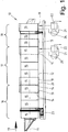
- the in the Fig. 1 The continuous washing machine 10 shown schematically has a cylindrical drum 12 which can be driven in rotation about a preferably horizontal axis of rotation 11.
- the axis of rotation 11 lies on the longitudinal central axis of the drum 12.
- the laundry to be washed is (based on the Fig. 1 ) is transported from left to right in the treatment direction 13 by the rotationally driven drum 12.
- a plurality of successive chambers 15 are formed by transverse partition walls 14 in the treatment direction.
- the chambers 15 may be the same size, but also different sizes.
- the partitions 14 have central or off-center (peripheral) openings which are not shown in the figure. Through the openings, the laundry can be transhipped by line in the treatment direction 13 of a chamber 15 in the subsequent chamber 15.
- the in the Fig. 1 shown continuous washing machine 10 has twelve chambers 15. However, the invention is not limited thereto.
- the continuous washing machine 10 may have a larger or smaller number of chambers 15.
- the first four chambers 15 seen in the treatment direction 13 form a prewashing zone 16 in the continuous washing machine 10 shown.
- the following five chambers 15 form a final wash zone 17 , Clearwash zone 17 and rinse zone 18 may be one of the in the Fig. 1 shown embodiment of the continuous washing machine 10 have different number of chambers 15. It is also conceivable that the rinsing zone 18 at least one further in the Fig. 1 not shown chamber to form a finishing zone follows. Also, the rinse zone 18 may be missing.
- the last chamber 15 of the prewash zone 16, the final wash zone 17 and the rinse zone 18 each have an outer drum 19.
- an outer drum 19 of the first chamber 15 of the final wash zone 17 and the rinse zone 18 is assigned. All outer drums 19 are equally formed liquid impermeable. So that treatment liquid for the laundry in the outer drum 19 with which the respective chamber 15 with an outer drum 19 extending portion of the drum 12 can communicate, the drum 12 in areas of those chambers 15, which is associated with an outer drum 19, at least partially formed permeable to treatment liquid, in particular perforated. As a result, treatment liquid can pass from the respective outer drum 19 into the liquid-permeable section of the drum 12 assigned to the chamber 15, and vice versa.
- the treatment liquid in the respective chamber 15 has a desired level.
- the water level is preferably slightly below the axis of rotation 11 (FIG. Fig. 2 and 3 ). Consequently, the surface of the treatment liquid in the respective chamber 15 is slightly below the axis of rotation 13th
- each of the identically formed outer drums 19 has in the lower region a preferably designed in the manner of a connection box extension.
- This extension receives a supply of the treatment liquid under the drum 12.
- components that are lighter than the treatment liquid for example, foam, lint and the like, collect.
- the lint is preferably at least largely bound in the foam.
- solid components of the treatment liquid may be collected, which are heavier than the treatment liquid.
- the heavier components are dirt washed out of the laundry and other solids, for example small foreign matter, which can pass through the perforation of the drum 12 in the region of the respective chamber 15 with the outer drum 19.
- the outer drum of the last chamber of the final wash zone 17 and the outer drum 19 of the last chamber 15 of the wash zone 18 are each assigned a circulation line 21 with a filter 22. These are the same at the end of the final wash zone 17 and at the end of the rinse zone 18.
- Both the circulation line 21 and the respective filter 22 are located outside the drum 12 and the outer drum 19.
- the respective filter 22 and its associated circulation line 21 are associated with a frame 23 of the continuous washing machine 10, in particular attached thereto.
- the filters 22 may also be located at a different location of the laundry away from the continuous washing machine 10.
- a pump 24 is provided behind the or each filter 22 for pumping back the filtered treatment liquid into the respective outer drum 19.
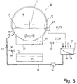
- the shows Fig. 2 in that the circulation line 21 is divided, namely that it is composed of an initial part viewed in the direction of flow to the filter 22 and a return part starting from the filter 22.
- the circulation line 21 is thereby interrupted, wherein the initial part and the return part of the circulation line 21 through the filter 22 but are fluidically connected.
- the initial part of the circulation line 21 is double-stranded, namely has a first initial part 25 and a second initial part 26.
- the first initial part 25 of the circulation line 21 is connected to a drain 27 of the outer drum 19, which is in the range of the level or the surface the treatment liquid in the chamber 15, which is associated with the outer drum 19 is located.
- the second starting part 26 of the circulating line 21 is connected to a second outflow 28 in the bottom area, in particular near the bottom 20, the outer drum 19 of the last chamber 15 of the final wash zone 17.
- the drain 28 may also be provided in the bottom 20 of the outer drum 19. Both starting parts 25 and 26 terminate before the filter 22.
- the return part of the circulation line 21 is assigned to that side of the filter 22 at which the filtered treatment liquid is obtained. By the pump 24 in the return part of the circulation line 21, the filtered liquid is pumped back into the outer drum 19.
- a feed 29 is provided for connecting a rear end of the return part of the circulation line 21 below the surface of the treatment liquid on the outer drum 19.
- the second initial part 26 of the circulation line 21 is assigned a valve 32.
- This is preferably an adjustable throttle valve, whereby the flow rate of the treatment liquid through the second initial part 26 is variable, but also the second starting part 26 can be closed.
- the inflow of treatment liquid from the bottom area of the outer drum 19 to the filter 22 can be completely inhibited or varied with respect to the volume flow of the treatment liquid per unit time to the filter 22, for example, to adjust the capacity of the filter 22.
- the circulation line 21 may be arranged a simple shut-off valve or an adjustable throttle valve.
- valve 33 is located in the return part of the circulation line 21, as seen in the flow direction of the treatment liquid behind the branch of the discharge line 30 from the circulation line 21. Also the discharge line 30 is associated with a valve 34. Through the valves 33 and 34, the outflow of the filtered treatment liquid can be selectively controlled, and selectively back to the outer drum 19 or in the collection tank 31st
- the filter 22 is detailed in FIG Fig. 5 shown.
- This is a so-called gravity filter, in which the treatment liquid to be filtered flows through a filter screen 31 due to gravity, namely from the top of the filter screen 48 to the bottom thereof. This can also take place during the flow of the treatment liquid to be filtered on the filter screen 48.
- the filter screen 48 is arranged in a preferably completely closed housing 35.
- the top of the housing 35 may be open.
- the housing 35 has (seen from the side) over an oblique course with an inclined bottom 36. From above, the ends of the two starting parts 25 and 26 of the circulation line 21 at the highest point in the oblique housing 35 out.
- the filter screen 48 is also mounted obliquely in the housing 35.
- the filter screen 48 thereby divides the housing 35 into a top 37 located above the surface of the filter screen 34 and a bottom 38 located below the filter screen 48.
- the filter screen 48 may be formed of a perforated plate having a uniform pitch of through holes of appropriate size or wire mesh be formed with appropriate mesh size.
- the filter screen 48 is preferably formed in two layers. This filter screen 48 is composed of a lower stable and coarse-meshed support grid and a finely meshed sieve arranged above it, which is formed like a lattice or braided. The optionally flexible screen is then carried by the support grid.
- the filter screen 48 terminates at a distance in front of a transverse wall 39 at the lower end of the housing 35.
- an adjustable in height transverse weir 40 Before the end of the filter screen 37 is an adjustable in height transverse weir 40. By corresponding height adjustment of the plate-like weir 40 is formed above the end of the lint filter 34, a gap corresponding width for the derivation of filtered out of the treatment liquid Ingredients.
- a hinged flap At the location of the height-adjustable weir 40 may also be provided a hinged flap.
- a chamber 42 for collecting the filtered-out from the treatment liquid components.
- a collecting container 43 may be provided for filtered-out components.
- the collecting container 43 is preferably removable from the chamber 42 or drawer-like withdrawn from the chamber 42.
- the housing 35 has a recess in the bottom 36, which forms a sump 44.
- the sump 44 as the lowest point of the housing 35 collects when emptying the filter 22, the remaining filtered treatment liquid.
- the sump 44 forms a pump template, which ensures that during operation of the filter 22, the pump 24 is always supplied with sufficiently filtered treatment liquid.
- a float switch 45 is also provided, which serves to prevent dry running of the pump 24.
- a closable drain 46 is located at the lowest point of the sump 44. When the drain 46 is open, the treatment liquid can be completely drained from the housing 35 of the filter 22.
- a plurality of directed against the underside of the filter screen 48 Abalismsdüsen 47 are provided in the lower part 38 of the housing 35 .
- the cleaning nozzles 47 are arranged distributed in the lower part 38 so that they can apply all or at least a majority of the underside of the filter screen 48 with cleaning liquid.
- the cleaning liquid is preferably fresh water. However, it is also possible to use filtered treatment liquid from the collection tank 31. The used cleaning liquid is then pumped back through the return part of the circulation line 21 and the discharge line 30 into the collection tank 31 or into a drain.
- the flow rate of the treatment liquid through the circulation line 21 is selected or adjusted at the throttle valve 32, that in the course of a treatment process of the laundry item in the respective chamber 15, the treatment liquid in this chamber 15 at least once completely rolled and filtered by the filter 22.
- the inventive method is designed so that it allows a multiple function of the filter 22.
- the filter 22 is thus used to fulfill different filtering tasks, which are schematically illustrated in FIGS Fig. 2 to 4 are shown.
- the Fig. 2 shows the use of the filter 22 for removing such components from the treatment liquid, which are lighter than the treatment liquid, for example foam, especially foam along with entrained fluff.
- the foam optionally with the fluff, collects on the surface 49 of the treatment liquid in the drum 12.
- the outflow 27 which is located in the region of the surface 49 of the treatment liquid, the foam with lint and other lighter constituents together with it on the surface 49 befindaji treatment liquid withdrawn from the drum 12 and the outer drum 19 via the drain 27 and placed over the first initial part 25 of the circulation line 21 to the filter 22.
- the treatment liquid with the lighter components passes into the upper part 37 of the housing 35 of the filter 22.
- the treatment liquid to be filtered flows with the lighter components to be filtered out on the filter screen 48.
- the filtered treatment liquid is then pumped through the pump 24 Circulation line 21 is pumped with the valve open 33 to the inlet 29 in the outer drum 19 and thus the filtered treatment liquid the washing process, namely the outer drum 19 and the drum 12, fed again.
- the filtered lighter components of the treatment liquid flow on the inclined filter 48. Through the gap under the transverse edge 41 of the weir 40 reach these filtered lighter components, in particular foam and lint, in the sump 43 of the filter 22. In the collecting 43 accumulate in particular lint, which can be disposed of from time to time by pulling or removing the Collecting container 43 from the chamber 42 of the housing 35 of the filter 22. Other components may collect at another location of the chamber 42 and be discharged therefrom, for example, in an outflow.
- the valves 32 and 34 are closed. Then, only light components are separated from the treatment liquid and the filtered treatment liquid in the circulation through the circulation line 21 is continuously pumped back into the continuous washing machine 10. Thus, the treatment liquid is continuously recycled treated treatment liquid again, so that the amount of treatment liquid in the respective chamber 15 substantially always remains the same and is reduced only to the located in the circulation line 21 and in the region of the filter 22 treatment liquid.
- the foam carpet on the treatment liquid is reduced, thereby enhancing the washing effect, whereby, in particular, stains can be more effectively removed from the laundry.
- the Fig. 3 schematically illustrates a second application of the filter 22.
- the valve 32 in the second initial part 26 of the circulation line 21 is so wide open or adjusted so that the treatment liquid is continuously fed to the filter 22 during the washing of the laundry.
- the preferably designed as a throttle valve 32 is set so that only a desired volume flow of the treatment liquid flows through the circulation line 21.
- the treatment liquid comes through the arranged close to the bottom 20 of the outer drum 19 drain 28 in the second initial part 26 a.
- the treatment liquid heavier components of the same, for example, removed from the laundry dirt particles, but also other small solid particles and possibly foreign body, via the drain 28 and the second initial part 26 of the circulation line 21 to the filter 22.
- the first starting part 25 of the circulation line 21 can be shut off in the embodiment shown by no valve. Therefore, on the surface 49 of the treatment liquid floating components are constantly passed through the first initial part 25 of the circulation line 21 to the filter 22.
- the second initial part 26 of the circulation line 21 flows through the second initial part 26 of the circulation line 21 as a result of this associated lockable and throttle valve 32 only treatment liquid with heavier components contained therein, if that is desired.
- the valve 32 may only be opened periodically during the wash.
- the valve 32 can also be constantly open, whereby only as much treatment liquid is guided through the throttle through the second initial part 26 to the filter 22, as the filter capacity permits. It is also conceivable, however, also to associate a valve with the first starting part 25 of the circulation line 21. When this is closed, with the valve 25 open in the second starting part 26, only treatment liquid with heavier constituents contained therein can be fed to the filter 22 and from this the treatment liquid can be freed of heavy constituents.
- the Fig. 4 shows the method according to a third operation of the filter 22.
- a bath change so an exchange of the treatment liquid, is carried out in the respective chamber 15.
- Such a bath change preferably takes place after washing the items of laundry in the relevant chamber 15, when the item of laundry is reloaded from the chamber 15 into the next in the treatment direction 13 chamber 15, for example, the first Chamber 15 of the rinsing zone 18, or to unload the fully washed and rinsed Wäschepostens from the continuous washing machine 10th
- the valve 32 in the second initial part 26 of the circulation line 21 and a possible valve in the first initial part 25 are preferably fully open.
- the treatment liquid can then be completely discharged from the drum 12 and its associated outer drum 19.
- the treatment liquid to be discharged is filtered, and then the filtered treatment liquid is passed from the pump 24 through the circulation line 21 with the valve 34 open in the discharge line 30 into the collecting tank 31.
- the following in the direction of flow of the treatment liquid through the circulation line 21 to the discharge line 30 valve 33 in the circulation line 21 is then preferably closed.
- the lower sump 44 in the housing 35 of the filter 22 makes it possible to discharge the treatment liquid completely from the filter 22 through the drain 46.
- the drain 46 leaves only the bottom of the sump 44 collecting residual treatment liquid not from the pump 24 in the Collection tank 31 can be pumped.
- mixing of the treatment liquid of the washing process last taken with optionally other treatment liquid for the next washing operation is avoided.
- the treatment liquid from the drum 12 and the outer drum 19 is completely drained, it is preferably carried out at the moment no filtering Deutschenmixdem filter 22, a cleaning of the filter screen 48. This is done from the bottom of the filter 48 through the directed to this Abalismsdüsen 47.
- the cleaning nozzles 47 can to be supplied with fresh water or purified treatment liquid from the collection tank 31 as a cleaning liquid.
- the contaminated cleaning liquid accumulating during cleaning of the filter screen 48 is discharged below the filter screen 48, that is to say in the lower part 38.
- the cleaning liquid collects in the sump 44 at the lowest point of the housing 35 of the filter 22 and is completely drained from here through the drain 46 and then disposed of.
- the cleaning of the filter 22 can also be done to in the operation of the filter 22 according to the Fig. 2 to destroy or reduce the amount of foam.
- the method works both in the last chamber 15 of the final wash zone 17 and the last chamber 15 of the rinse zone 18th
- 16 can be moved to the last chamber 15 of the prewash zone as well.
- the method described above is also suitable for continuous washing machines which have only one pre-wash zone 16 and one final wash zone 17, but no rinse zone 18.
- the invention is not only suitable for continuous washing machines of all kinds, but also for other washing machines and washing machines for washing or cleaning any other objects, so not only laundry.
Description
Die Erfindung betrifft ein Verfahren zum Waschen von insbesondere Wäschestücken gemäß dem Oberbegriff des Anspruch 1. Des Weiteren betrifft die Erfindung eine Vorrichtung zum Waschen von insbesondere Wäschestücken gemäß dem Oberbegriff des Anspruchs 7 (siehe
Infolge der beim Waschen Vollkreisdrehungen oder gegensinnige Teilkreisdrehungen (schwenkende Bewegungen) ausführenden Trommel kommt es zu einer Schaumbildung, die vor allem durch die Behandlungszusätze in der Behandlungsflüssigkeit hervorgerufen wird. Der Schaum lagert sich mit mindestens teilweise gebundenen Flusen von der zu waschenden Wäsche an der Oberfläche der Behandlungsflüssigkeit ab. Außerdem nimmt die Behandlungsflüssigkeit aus der Wäsche herausgewaschenen Schmutz und gegebenenfalls Fremdstoffe auf, die größtenteils schwerer als die Behandlungsflüssigkeit sind und sich deshalb im Bodenbereich der Außentrommel ansammeln. Der Schaum und der Schmutz beeinträchtigen die Wirksamkeit des Waschvorgangs.As a result of the washing during full circle rotations or opposing pitch circle rotations (pivoting movements) exporting drum, there is a foaming, caused mainly by the treatment additives in the treatment liquid becomes. The foam settles with at least partially bound lint from the laundry to be washed on the surface of the treatment liquid. In addition, the treatment liquid takes out of the laundry washed-out dirt and possibly foreign matter, which are mostly heavier than the treatment liquid and therefore accumulate in the bottom area of the outer drum. The foam and dirt affect the effectiveness of the washing process.
Aus der
Der Erfindung liegt die Aufgabe zugrunde, ein Verfahren und eine Vorrichtung zum wirksameren Waschen und/oder Spülen von Wäschestücken und anderen Gegenständen zu schaffen.The invention has for its object to provide a method and apparatus for more effective washing and / or rinsing laundry items and other objects.
Ein Verfahren zur Lösung dieser Aufgabe weist die Maßnahmen des Anspruchs 1 auf. Demnach wird die Behandlungsflüssigkeit, vorzugsweise immer nur ein Teil der Behandlungsflüssigkeit, während der Behandlung, das heißt insbesondere des Waschens und Spülens der Wäschestücke oder anderer Gegenstände, außerhalb der Trommel und der mindestens einen dieser zugeordneten Außentrommel gefiltert. Weil die Filterung während des Waschvorgangs erfolgt, werden sukzessive den Waschvorgang beeinträchtigende Begleitstoffe aus der Behandlungsflüssigkeit entfernt. Das Waschen kann dann wegen der geringeren Belastung der Behandlungsflüssigkeit durch die Begleitstoffe effektiver erfolgen. Durch die Filterung außerhalb der Waschmaschine wird der Waschvorgang nicht beeinträchtigt. Weiterhin werden wahlweise, insbesondere abwechselnd, leichtere und schwere Bestandteile aus der Behandlungsflüssigkeit ausgefiltert. Es können somit sowohl sich auf der Oberfläche der Behandlungsflüssigkeit ansammelnde Bestandteile wie Schaum, Flusen oder dergleichen und auf den Boden der Außentrommel absinkende schwere Bestandteile wie Schmutzpartikel, Fremdstoffe oder dergleichen nach und nach aus der Behandlungsflüssigkeit ausgefiltert werden. Es ist alternativ auch denkbar, gleichzeitig ein Gemisch aus Behandlungsflüssigkeit mit leichteren Bestandteilen und schweren Bestandteilen aus der Außentrommel abzuziehen und gemeinsam zu filtern. Außerdem wird zum Ausfiltern leichter Bestandteile aus der Behandlungsflüssigkeit die Behandlungsflüssigkeit im Bereich ihrer Oberfläche, und zwar an der Oberfläche oder dicht unterhalb der Oberfläche, aus der Außentrommel entnommen, während die Behandlungsflüssigkeit mit schwereren Bestandteilen unterhalb der Oberfläche der Behandlungsflüssigkeit, vor allem am Boden oder im Bereich des Bodens der Außentrommel, aus demselben abgezogen wird. Durch die verschiedenen Entnahmemöglichkeiten der zu filternden Behandlungsflüssigkeit aus der Außentrommel hat der Filter mehrere Funktionen, indem er sowohl leichtere als auch schwerere Bestandteile jeweils getrennt oder auch gemeinsam aus der Behandlungsflüssigkeit herausfiltern kann.A method for achieving this object comprises the measures of claim 1. Accordingly, the treatment liquid, preferably always only a part of the treatment liquid, during the treatment, that is to say in particular the washing and rinsing of the laundry items or other objects, outside the drum and the at least one associated outer drum is filtered. Because the filtering takes place during the washing process, accompanying substances which impair the washing process are gradually removed from the treatment liquid. The washing can then be done more effectively because of the lower burden of the treatment liquid by the accompanying substances. Filtering outside the washing machine does not affect the washing process. Furthermore, optionally, in particular alternately, lighter and heavier components are filtered out of the treatment liquid. Thus, both components accumulating on the surface of the treatment liquid, such as foam, lint or the like, and heavy components sinking to the bottom of the outer drum, such as dirt particles, foreign matter or the like, can be gradually filtered out of the treatment liquid. Alternatively, it is also conceivable to simultaneously remove a mixture of treatment liquid with lighter components and heavy components from the outer drum and to filter together. In addition, for filtering out light components from the treatment liquid, the treatment liquid in the region of its surface, on the surface or just below the surface, is removed from the outer drum while the treatment liquid with heavier constituents below the surface of the treatment liquid, especially at the bottom or in the region of the bottom of the outer drum, is withdrawn from the same. Due to the different removal possibilities of the treatment liquid to be filtered from the outer drum, the filter has several functions in that it can separate both lighter and heavier components separately or together from the treatment liquid.
Bevorzugt erfolgt das Filtern der Behandlungsflüssigkeit beim Waschen kontinuierlich. Dadurch werden sich in der Behandlungsflüssigkeit während des Waschvorgangs neu ansammelnde Begleitstoffe, insbesondere Schaum, Flusen, Schmutzreste und dergleichen, nach und nach ausgefiltert, und zwar vorzugsweise laufend, insbesondere während des gesamten Waschvorgangs.The filtering of the treatment liquid preferably takes place continuously during washing. As a result, in the treatment liquid during the washing process newly accumulating impurities, in particular foam, fluff, dirt and the like, are filtered out gradually, preferably continuously, especially during the entire washing process.
Bevorzugt ist es vorgesehen, dass die kontinuierliche Filterung der Behandlungsflüssigkeit in der Weise erfolgt, dass die Behandlungsflüssigkeit sukzessive im Kreislauf durch bzw. über den Filter gepumpt wird. Dadurch wird immer ein Teil der Behandlungsflüssigkeit der Filterung unterzogen, während der übrige Teil, vor allem ein Großteil, der Behandlungsflüssigkeit in der Außentrommel der drehend antreibbaren Trommel verbleibt, wodurch der Waschvorgang trotz der dabei gleichzeitig erfolgenden sukzessiven und/oder kontinuierlichen Filterung eines Teils der Behandlungsflüssigkeit ohne Leistungseinbußen aufrechterhalten bleibt.It is preferably provided that the continuous filtering of the treatment liquid takes place in such a manner that the treatment liquid is successively pumped in circulation through or over the filter. Thereby, a part of the treatment liquid is always subjected to the filtering, while the remaining part, mainly a large part of the treatment liquid remains in the outer drum of the rotary drivable drum, whereby the washing process despite the simultaneous successive successive and / or continuous filtering of a portion of the treatment liquid without sacrificing performance.
Bei einer vorteilhaften Weiterbildung des Verfahrens wird an mindestens einem Auslass ein kontinuierlicher Strom der Behandlungsflüssigkeit aus der Außentrommel abgelassen und diese Behandlungsflüssigkeit nach dem Filtern der Außentrommel wieder zugeführt. Dadurch wird stets ein kleiner Teil der Behandlungsflüssigkeit im Kreislauf am Filter vorbeigeführt und kontinuierlich der Filter mit zu filternder Behandlungsflüssigkeit beaufschlagt. Der Volumenstrom der Behandlungsflüssigkeit, der über den Filter geleitet wird, ist so gewählt, dass er der Leistungsfähigkeit des Filters entspricht und die Menge der in der Außentrommel und der die zu behandelnde Wäsche enthaltenden Trommel verbleibenden Behandlungsflüssigkeit nicht nennenswert verringert wird, so dass der Pegel der Behandlungsflüssigkeit in der Trommel den Sollpegelstand nicht unterschreitet.In an advantageous development of the method, a continuous stream of the treatment liquid is discharged from the outer drum at at least one outlet, and this treatment liquid is fed again after filtering the outer drum. As a result, a small part of the treatment liquid is always conducted past the filter in the circuit and continuously applied to the filter to be filtered with the treatment liquid. The volume flow of the treatment liquid which is passed over the filter is selected so that it corresponds to the performance of the filter and the amount of treatment liquid remaining in the outer drum and the drum to be treated is not appreciably reduced, so that the level of the Treatment liquid in the drum does not fall below the nominal level.
Es ist vorzugsweise vorgesehen, den mindestens einen Filter auch zu benutzen, um am Ende des Waschvorgangs aus der Außentrommel abzulassende Behandlungsflüssigkeit zu filtern. Dadurch ist eine weitere Verwendungsmöglichkeit des gleichen Filters gegeben. Durch die Filterung außerhalb der Außentrommel kann auch die aus der Außentrommel abzulassende Behandlungsflüssigkeit vollständig gefiltert werden. Die gefilterte Behandlungsflüssigkeit wird vorzugsweise in einen Speichertank geleitet. Aus dem Sammel- oder Speichertank kann die gefilterte und benutzte Behandlungsflüssigkeit einer geeigneten Wiederverwendung zugeführt werden.It is preferably provided to also use the at least one filter to filter at the end of the washing process to be discharged from the outer drum treatment liquid. As a result, a further possible use of the same filter is given. By filtering outside the outer drum can also be out of the outer drum To be drained treatment liquid to be completely filtered. The filtered treatment liquid is preferably passed into a storage tank. From the collection or storage tank, the filtered and used treatment liquid may be supplied for proper reuse.
Nach einer weiteren bevorzugten Ausgestaltung des Verfahrens wird die Behandlungsflüssigkeit mit einem Schwerkraftfilter gefiltert. Die Behandlungsflüssigkeit kann dadurch frei durch den Filter strömen, wobei schwerkraftbedingt die gefilterte Behandlungsflüssigkeit von den ausgefilterten Bestandteilen getrennt wird. Alternativ oder zusätzlich kann es vorgesehen sein, die Flüssigkeit durch Schwerkraft frei fließend zum Filter strömen zu lassen. Der Filter wird dadurch gleichmäßig mit der der Schwerkraft folgenden Behandlungsflüssigkeit beaufschlagt und genauso die Filterung vorgenommen. Dabei ist es aber denkbar, dass die Fließgeschwindigkeit bzw. die Menge der pro Zeiteinheit dem Filter zugeführten Behandlungsflüssigkeit einstellbar bzw. veränderlich ist durch zum Beispiel ein verstellbares Drosselventil in einer Zuleitung zum Filter. Dadurch kann die dem Filter pro Zeiteinheit zugeführte Behandlungsflüssigkeit an die Leistungsfähigkeit des Filters angepasst und so eine optimale Filterung herbeigeführt werden.According to a further preferred embodiment of the method, the treatment liquid is filtered with a gravity filter. As a result, the treatment liquid can flow freely through the filter, whereby the filtered treatment liquid is separated from the filtered-out components by gravity. Alternatively or additionally, it may be provided to allow the liquid to flow freely by gravity to the filter. The filter is thereby applied uniformly with the gravity of the following treatment liquid and made the same filtering. However, it is conceivable that the flow rate or the amount of treatment fluid supplied to the filter per unit of time is adjustable or variable by, for example, an adjustable throttle valve in a supply line to the filter. As a result, the treatment liquid supplied to the filter per unit time can be adapted to the performance of the filter and thus optimal filtering be brought about.
Eine Vorrichtung zur Lösung der eingangs genannten Aufgabe, wobei es sich vorzugsweise um eine Waschmaschine handelt, weist die Merkmale des Anspruchs 7 auf. Dadurch, dass mindestens einer Außentrommel eine Umlaufleitung mit einem Filter zugeordnet ist, kann die Filterung der Behandlungsflüssigkeit während des Waschvorgangs, nämlich der Vorwäsche, Klärwäsche und/oder des Spülens, erfolgen, und zwar insbesondere kontinuierlich. Dadurch steht dem Waschvorgang stets mindestens teilweise von den Waschvorgang beeinträchtigenden Bestandteilen, vor allem Schaum, befreite Behandlungsflüssigkeit zur Verfügung. Die Umlaufleitung ist mit mehreren, insbesondere einzeln absperrbaren, Abflüssen aus der jeweiligen Außentrommel versehen. Dabei ist ein oberer Abfluss im Bereich des Pegelstands der Behandlungsflüssigkeit in der Trommel und der Außentrommel angeordnet, während ein anderer Abfluss vorzugsweise im Bereich des Bodens oder im Boden der Außentrommel vorgesehen ist. Auf diese Weise kann aus der Außentrommel sowohl Behandlungsflüssigkeit mit darauf schwimmenden Begleitstoffen aus dem Bereich der Oberfläche der Behandlungsflüssigkeit als auch Behandlungsflüssigkeit mit absinkenden Begleitstoffen abgezogen werden. Durch die Absperrbarkeit mindestens eines Abflusses ist es möglich, selektiv von oben oder von unten Behandlungsflüssigkeit aus der Außentrommel abzuziehen oder gewünschtenfalls auch gleichzeitig Behandlungsflüssigkeit mit schwimmenden und abgesunkenen Begleitstoffen der Außentrommel zu entnehmen.A device for solving the above-mentioned object, wherein it is preferably a washing machine, has the features of claim 7. Characterized in that at least one outer drum is associated with a circulation line with a filter, the filtering of the treatment liquid during the washing process, namely the pre-wash, Klärwäsche and / or rinsing, take place, in particular continuously. As a result, the washing process is always at least partially from the washing process affecting components, especially foam, liberated treatment liquid available. The circulation line is provided with several, in particular individually lockable, drains from the respective outer drum. In this case, an upper outflow in the region of the level of the treatment liquid in the drum and the outer drum is arranged, while another outflow is preferably provided in the region of the bottom or in the bottom of the outer drum. In this way, both treatment liquid with accompanying substances flowing therefrom from the area of the surface of the treatment liquid and also treatment liquid with decreasing impurities can be withdrawn from the outer drum. Due to the closable nature of at least one outflow, it is possible to withdraw treatment liquid from the outer drum selectively from above or from below or, if desired, to simultaneously remove treatment liquid with floating and sunken accompanying substances from the outer drum.
Eine andere vorteilhafte Ausgestaltung der Vorrichtung sieht es vor, in der Umlaufleitung bzw. Kreislaufleitung vorzugsweise in Strömungsrichtung der Behandlungsflüssigkeit gesehen hinter dem mindestens einen Filter wenigstens eine Pumpe vorzusehen. Durch die Pumpe kann die gefilterte Flüssigkeit zurückgepumpt werden in vorzugsweise dieselbe, gegebenenfalls auch eine andere, Außentrommel, aus der die Behandlungsflüssigkeit entnommen worden ist, auch wenn sich die Stelle der Einleitung der gefilterten Flüssigkeit in die Außentrommel höher befindet als der Filter.Another advantageous embodiment of the device provides, seen in the circulation line or circulation line preferably provided in the flow direction of the treatment liquid behind the at least one filter at least one pump. By the pump, the filtered liquid can be pumped back into preferably the same, optionally also another, external drum from which the treatment liquid has been removed, even if the point of introduction of the filtered liquid into the outer drum is higher than the filter.
Es kann vorgesehen sein, dass die Umlaufleitung vorzugsweise hinter der Pumpe mit einem bevorzugt absperrbaren Zufluss zur Außentrommel verbunden ist. Durch die Absperrbarkeit des Zuflusses ist es möglich, gefilterte Behandlungsflüssigkeit zu einer anderen Stelle zu pumpen. Beispielsweise kann die Umlaufleitung einen Abfluss aufweisen, dem vorzugsweise mindestens ein Sammeltank zugeordnet ist. Der Abfluss kann sich in Strömungsrichtung gesehen vor der Pumpe befinden, wenn die gefilterte Behandlungsflüssigkeit durch Schwerkraft ableitbar ist. Hingegen ist es sinnvoll, den Abfluss in Strömungsrichtung hinter der Pumpe anzuordnen, wenn die gefilterte Behandlungsflüssigkeit zum höher liegenden Abfluss gepumpt werden muss.It can be provided that the circulation line is preferably connected behind the pump with a preferably closable inflow to the outer drum. Due to the closeability of the inflow, it is possible to pump filtered treatment liquid to another location. For example, the circulation line can have an outflow, to which preferably at least one collection tank is assigned. The drain can be seen in the flow direction in front of the pump when the filtered treatment liquid is derived by gravity. On the other hand, it makes sense to arrange the downstream flow behind the pump when the filtered treatment liquid needs to be pumped to the higher drain.
Bei einer bevorzugten Vorrichtung ist der mindestens eine Filter als ein Schwerkraftfilter ausgebildet. Dieser Filter arbeitet selbsttätig. Vor allem braucht die zu filternde Behandlungsflüssigkeit nicht durch eine Pumpe durch den Schwerkraftfilter hindurchgepumpt zu werden. Vielmehr kann die Behandlungsflüssigkeit aus der Außentrommel aufgrund ihrer potentiellen Energie selbsttätig zum Filter und durch bzw. über denselben strömen. Ein solcher Filter kann als ein Sieb ausgebildet sein, durch dessen Öffnung die zu filternde Behandlungsflüssigkeit hindurchfließt, aber sowohl schwerere als auch leichtere Begleitstoffe zurückhält, so dass diese auf der vom Sieb gebildeten Filterfläche, die einen geraden, schrägen und/oder auch gewölbten Verlauf aufweisen kann, abführbar sind.In a preferred device, the at least one filter is designed as a gravity filter. This filter works automatically. Above all, the treatment liquid to be filtered need not be pumped through the gravity filter by a pump. Rather, the treatment liquid from the outer drum due to their potential energy can flow automatically to the filter and through or over the same. Such a filter may be formed as a sieve, through the opening of which the treatment liquid to be filtered flows, but retains both heavier and lighter impurities, so that they have on the filter surface formed by the filter, which have a straight, oblique and / or curved course can, are deductible.
Zur Reinigung der Filterfläche, insbesondere des Filtersiebs, können diese mit einem strömenden Fluid beaufschlagt werden, beispielsweise durch Sprühdüsen unter der vorzugsweise siebartigen Filterfläche.To clean the filter surface, in particular the filter screen, they can be acted upon by a flowing fluid, for example by spray nozzles under the preferably sieve-like filter surface.
Die Erfindung eignet sich besonders für Vorrichtungen, die nach Art gewerblicher Waschmaschinen, nämlich sogenannter Durchlaufwaschmaschinen, ausgebildet sind. Eine solche Waschmaschine verfügt über eine längliche, insgesamt drehend antreibbare Trommel mit mehreren aufeinanderfolgenden Kammern, wobei mindestens einer Kammer eine Außentrommel zugeordnet ist. Üblicherweise befindet sich eine Außentrommel dort, wo Behandlungsflüssigkeit, wie Vorwaschflüssigkeit, Klarwaschflüssigkeit und/oder Spülflüssigkeit, aus der Trommel ableitbar ist oder Flüssigkeiten der Trommel zuführbar sind. Durch die Zuordnung der Außentrommel zu mindestens einer Kammer ermöglicht es die Erfindung, bei einer Durchlaufwaschmaschine kammerbezogen immer nur die in der betreffenden Kammer vorhandene Behandlungsflüssigkeit während des Waschvorgangs vorzugsweise kontinuierlich zu filtern, und zwar insbesondere sowohl leichtere Bestandteile als auch schwere Bestandteile sukzessive, aber ständig, vor allem kontinuierlich, aus der Behandlungsflüssigkeit in der betreffenden Kammer mindestens teilweise zu entfernen.The invention is particularly suitable for devices which are designed in the manner of commercial washing machines, namely so-called continuous washing machines. Such a washing machine has an elongated drum which can be driven in total in rotation and has a plurality of successive chambers, wherein at least one chamber is assigned an outer drum. Usually, an outer drum is located there, where treatment liquid, such as prewash liquid, clear wash liquid and / or rinse liquid, is derivable from the drum or liquids are fed to the drum. By assigning the outer drum to at least one chamber, the invention allows for a continuous washing machine chamber-related always preferably only present in the relevant chamber treatment liquid during the washing process continuously, in particular both lighter components and heavy components successively, but constantly, especially continuously, at least partially to remove from the treatment liquid in the chamber in question.
Ein bevorzugtes Ausführungsbeispiel der Erfindung wird nachfolgend anhand der Zeichnung näher erläutert. In dieser zeigen:
- Fig. 1
- eine schematische Seitenansicht einer als Durchlaufwaschmaschine ausgebildeten erfindungsgemäßen Vorrichtung,
- Fig. 2
- einen Querschnitt durch eine mit einer Außentrommel versehene Kammer der Durchlaufwaschmaschine der
Fig. 1 in einer schematischen Darstellung, - Fig. 3
- einen Querschnitt analog zur
Fig. 2 bei einer anderen Betriebsweise, - Fig. 4
- einen Querschnitt analog zur
Fig. 2 in einer wiederum anderen Betriebsweise, und - Fig. 5
- einen Längsschnitt durch einen in den
Fig. 1 bis 4 nur schematisch dargestellten Filter.
- Fig. 1
- a schematic side view of a trained as a continuous washing machine device according to the invention,
- Fig. 2
- a cross section through a provided with an outer drum chamber of the continuous washing machine of
Fig. 1 in a schematic representation, - Fig. 3
- a cross section analogous to
Fig. 2 in another mode of operation, - Fig. 4
- a cross section analogous to
Fig. 2 in another turn, and - Fig. 5
- a longitudinal section through a in the
Fig. 1 to 4 only schematically illustrated filter.
Die Erfindung wird nachfolgend anhand einer als Durchlaufwaschmaschine 10 ausgebildeten Vorrichtung zum Waschen und Spülen von Wäschestücken beschrieben. Hierauf ist die Erfindung aber nicht beschränkt.The invention will be described below with reference to a device designed as a
Die in der
In der Trommel 12 sind durch quergerichtete Trennwände 14 mehrere in Behandlungsrichtung 13 aufeinanderfolgende Kammern 15 gebildet. In jeder Kammer 15 wird jeweils ein Wäscheposten behandelt, insbesondere gewaschen und gespült. Die Kammern 15 können gleich groß, aber auch unterschiedlich groß sein. Die Trennwände 14 verfügen über mittige oder außermittige (am Rand liegende) Öffnungen, die in der Figur nicht gezeigt sind. Durch die Öffnungen kann die Wäsche postenweise in Behandlungsrichtung 13 von einer Kammer 15 in die darauffolgende Kammer 15 umgeladen werden. Die in der
Die in Behandlungsrichtung 13 gesehen ersten vier Kammern 15 bilden bei der gezeigten Durchlaufwaschmaschine 10 eine Vorwaschzone 16. Die darauffolgenden fünf Kammern 15 bilden eine Klarwaschzone 17. In Behandlungsrichtung 13 gesehen folgt auf die Klarwaschzone 17 eine Spülzone 18 mit drei aufeinanderfolgenden Kammern 15. Die Vorwaschzone 16, Klarwaschzone 17 und Spülzone 18 können eine vom in der
Bei der hier gezeigten Durchlaufwaschmaschine 10 weist jeweils die letzte Kammer 15 der Vorwaschzone 16, der Klarwaschzone 17 und der Spülzone 18 eine Außentrommel 19 auf. Außerdem ist eine Außentrommel 19 der ersten Kammer 15 der Klarwaschzone 17 und der Spülzone 18 zugeordnet. Alle Außentrommeln 19 sind gleichermaßen flüssigkeitsundurchlässig ausgebildet. Damit Behandlungsflüssigkeit für die Wäsche in der Außentrommel 19 mit dem sich über die betreffende Kammer 15 mit einer Außentrommel 19 erstreckenden Abschnitt der Trommel 12 kommunizieren kann, ist die Trommel 12 in Bereichen derjenigen Kammern 15, denen eine Außentrommel 19 zugeordnet ist, mindestens teilweise für Behandlungsflüssigkeit durchlässig ausgebildet, insbesondere perforiert. Dadurch kann Behandlungsflüssigkeit von der jeweiligen Außentrommel 19 in den der Kammer 15 zugeordneten, flüssigkeitsdurchlässigen Abschnitt der Trommel 12 gelangen und umgekehrt. Die Behandlungsflüssigkeit in der jeweiligen Kammer 15 verfügt über einen gewünschten Pegelstand. Der Pegelstand liegt bevorzugt etwas unterhalb der Drehachse 11 (
Vorzugsweise jede der gleich ausgebildeten Außentrommeln 19 weist im unteren Bereich eine vorzugsweise nach Art eines Anschlusskastens ausgebildete Erweiterung auf. Diese Erweiterung nimmt einen Vorrat der Behandlungsflüssigkeit unter der Trommel 12 auf.Preferably, each of the identically formed
Auf der Oberfläche der Behandlungsflüssigkeit sammeln sich Bestandteile, die leichter sind als die Behandlungsflüssigkeit, beispielsweise Schaum, Flusen und dergleichen. Die Flusen sind vorzugsweise mindestens größtenteils im Schaum gebunden. Auf einem Boden 20 der zur Bildung des Anschlusskastens unten erweiterten Außentrommel 19 können sich feste Bestandteile der Behandlungsflüssigkeit sammeln, die schwerer sind als die Behandlungsflüssigkeit. Bei den schwereren Bestandteilen handelt es sich um aus der Wäsche ausgewaschenen Schmutz und andere Feststoffe, beispielsweise kleine Fremdkörper, die durch die Perforation der Trommel 12 im Bereich der jeweiligen Kammer 15 mit der Außentrommel 19 hindurchtreten können.On the surface of the treatment liquid, components that are lighter than the treatment liquid, for example, foam, lint and the like, collect. The lint is preferably at least largely bound in the foam. On a bottom 20 of the
Bei der hier gezeigten Durchlaufwaschmaschine 10 ist der Außentrommel der letzten Kammer der Klarwaschzone 17 und der Außentrommel 19 der letzen Kammer 15 der Spülzone 18 jeweils eine Umlaufleitung 21 mit einem Filter 22 zugeordnet. Diese sind am Ende der Klarwaschzone 17 und am Ende der Spülzone 18 gleich ausgebildet. Sowohl die Umlaufleitung 21 als auch der jeweilige Filter 22 befinden sich außerhalb der Trommel 12 und der Außentrommel 19. Vorzugsweise sind der jeweilige Filter 22 und die ihm zugeordnete Umlaufleitung 21 einem Rahmengestell 23 der Durchlaufwaschmaschine 10 zugeordnet, insbesondere hieran befestigt. Die Filter 22 können sich aber auch an einer anderen Stelle der Wäscherei entfernt von der Durchlaufwaschmaschine 10 befinden. In Strömungsrichtung der Behandlungsflüssigkeit durch die Umlaufleitung 21 gesehen ist hinter dem bzw. jedem Filter 22 eine Pumpe 24 vorgesehen zum Zurückpumpen der gefilterten Behandlungsflüssigkeit in die jeweilige Außentrommel 19.In the
Die
Insbesondere zeigt die
Vom Rücklaufteil der Umlaufleitung 21 zweigt hinter der Pumpe 24 eine Auslaufleitung 30 ab, die zu einem Sammeltank 31 führt bzw. in den Sammeltank 31 mündet.From the return part of the
Dem zweiten Anfangsteil 26 der Umlaufleitung 21 ist ein Ventil 32 zugeordnet. Hierbei handelt es sich vorzugsweise um ein verstellbares Drosselventil, womit die Durchflussrate der Behandlungsflüssigkeit durch den zweiten Anfangsteil 26 veränderlich ist, aber auch der zweite Anfangsteil 26 geschlossen werden kann. Auf diese Weise kann der Zufluss von Behandlungsflüssigkeit aus dem Bodenbereich der Außentrommel 19 zum Filter 22 ganz unterbunden oder hinsichtlich des Volumenstroms der Behandlungsflüssigkeit pro Zeiteinheit zum Filter 22 verändert werden, beispielsweise zur Anpassung der Kapazität des Filters 22. Ebenso kann bei Bedarf im ersten Anfangsteil 25 der Umlaufleitung 21 ein einfaches Absperrventil oder ein verstellbares Drosselventil angeordnet sein. Dann können gezielt Teilströme von der Oberfläche zur Behandlungsflüssigkeit und vom Boden der Außentrommel 19 gleichzeitig zum Filter 22 geleitet werden, die Durchflussrate der Behandlungsflüssigkeit durch den ersten Anfangsteil 25 verändert werden und gegebenenfalls der erste Anfangsteil 25 der Umlaufleitung 21 auch ganz verschlossen werden. Ein weiteres Ventil 33 befindet sich im Rücklaufteil der Umlaufleitung 21, und zwar in Strömungsrichtung der Behandlungsflüssigkeit gesehen hinter der Abzweigung der Auslaufleitung 30 von der Umlaufleitung 21. Auch der Auslaufleitung 30 ist ein Ventil 34 zugeordnet. Durch die Ventile 33 und 34 kann der Abfluss der gefilterten Behandlungsflüssigkeit gezielt gesteuert werden, und zwar wahlweise zurück zur Außentrommel 19 oder in den Sammeltank 31.The second initial part 26 of the
Der Filter 22 ist detailliert in der
Das Filtersieb 48 ist bevorzugt zweilagig ausgebildet. Dieses Filtersieb 48 setzt sich zusammen aus einem unteren stabilen und grobmaschigen Stützgitter und einem darüber angeordneten feinmaschigen Sieb, das gitterartig oder geflochten ausgebildet ist. Das gegebenenfalls flexible Sieb wird dann vom Stützgitter getragen.The
Das Filtersieb 48 endet mit Abstand vor einer Querwandung 39 am tieferliegenden Ende des Gehäuses 35. Vor dem Ende des Filtersiebs 37 befindet sich ein in der Höhe verstellbares quergerichtetes Wehr 40. Durch entsprechende Höhenverstellung des plattenartigen Wehrs 40 entsteht oberhalb des Endes des Flusensiebs 34 ein Spalt entsprechender Breite zur Ableitung der aus der Behandlungsflüssigkeit ausgefilterten Bestandteile. An der Stelle des höhenverstellbaren Wehrs 40 kann auch eine schwenkbare Klappe vorgesehen sein. Zwischen dem von der Querwand 39 beabstandeten Ende des Filtersiebs 48, das von einem unteren Querrand 41 desselben gebildet ist, befindet sich eine Kammer 42 zum Sammeln der aus der Behandlungsflüssigkeit herausgefilterten Bestandteile. In der Kammer 42 kann ein Sammelbehälter 43 für ausgefilterte Bestandteile vorgesehen sein. Der Sammelbehälter 43 ist vorzugsweise aus der Kammer 42 herausnehmbar oder schubladenartig aus der Kammer 42 herausziehbar.The
Am unten liegenden Endbereich vor der Querwandung 39 weist das Gehäuse 35 eine Vertiefung im Boden 36 auf, die einen Sumpf 44 bildet. Im Sumpf 44 als tiefste Stelle des Gehäuses 35 sammelt sich beim Entleeren des Filters 22 die restliche gefilterte Behandlungsflüssigkeit. Außerdem bildet der Sumpf 44 eine Pumpenvorlage, die sicherstellt, dass beim Betrieb des Filters 22 die Pumpe 24 stets mit genügend gefilterter Behandlungsflüssigkeit versorgt wird. Im Sumpf 44 ist außerdem ein Schwimmerschalter 45 vorgesehen, der zur Verhinderung eines Trockenlaufs der Pumpe 24 dient. Weiterhin befindet sich an der tiefsten Stelle des Sumpfs 44 ein verschließbarer Abfluss 46. Bei geöffnetem Abfluss 46 kann die Behandlungsflüssigkeit vollständig aus dem Gehäuse 35 des Filters 22 abgelassen werden.At the lower end region in front of the
Im Unterteil 38 des Gehäuses 35 sind mehrere gegen die Unterseite des Filtersiebs 48 gerichtete Abreinigungsdüsen 47 vorgesehen. Die Abreinigungsdüsen 47 sind so im Unterteil 38 verteilt angeordnet, dass sie die ganze oder zumindest einen Großteil der Unterseite des Filtersiebs 48 mit Reinigungsflüssigkeit beaufschlagen können. Bei der Reinigungsflüssigkeit handelt es sich bevorzugt um Frischwasser. Es kann aber auch gefilterte Behandlungsflüssigkeit aus dem Sammeltank 31 verwendet werden. Die gebrauchte Reinigungsflüssigkeit wird dann durch den Rücklaufteil der Umlaufleitung 21 und die Auslaufleitung 30 wieder zurückgepumpt in den Sammeltank 31 oder in einen Abfluss geleitet.In the
Nachfolgend wird das erfindungsgemäße Verfahren anhand der zuvor beschriebenen Vorrichtung, nämlich der Durchlaufwaschmaschine 10, näher beschrieben:
- Das erfindungsgemäße Verfahren sieht es vor, bezogen auf die jeweilige
Kammer 15 mit einerAußentrommel 19 außerhalb der Außentrommel 19 die Behandlungsflüssigkeit während des Waschvorgangs vorzugsweise kontinuierlich zu filtern. Es kann die Behandlungsflüssigkeit aus jeder Außentrommel 19 oder auch nur ausgewählten Außentrommeln 19 oder nur einer Außentrommel 19 gefiltert werden. Die Filtration kann während des Waschvorgangs periodisch erfolgen, aber auch fortdauernd während des gesamten Waschvorgangs. Es wird bei der Filtration während des Waschvorgangs durch dieUmlaufleitung 21 ein von der Behandlungsflüssigkeit kontinuierlich abgeführter kleiner Teil der Behandlungsflüssigkeit von der Pumpe 24 durch die Umlaufleitung 21 gepumpt und dabei vom alsSchwerkraftfilter ausgebildeten Filter 22 nach dem Schwerkraftprinzip gefiltert. Der Filterung wird immer nur ein solcher kleiner Teil der Behandlungsflüssigkeit unterzogen, dass der vorgesehene Pegel der Behandlungsflüssigkeit in der die zu waschende Wäschestücke aufnehmenden Trommel 12 und der Außentrommel 19 das vorgesehene Niveau beibehält. Im gezeigten Ausführungsbeispiel ist das Niveau der Behandlungsflüssigkeit inder Trommel 12 so gewählt, dass dieOberfläche 49 der Behandlungsflüssigkeit etwas unterhalb der Drehachse 11der Trommel 12 liegt (Fig. 2 bis 4 ).
- The method according to the invention provides, with respect to the
respective chamber 15 with anouter drum 19 outside theouter drum 19, preferably to continuously filter the treatment liquid during the washing process. The treatment liquid can be filtered out of anyouter drum 19 or only selectedouter drums 19 or only oneouter drum 19. The filtration can during the washing period, but also continuously during the entire washing process. During filtration, during the washing process by thecirculation line 21, a small portion of the treatment liquid continuously discharged from the treatment liquid is pumped by thepump 24 through thecirculation line 21 and filtered by the gravity-flow filter 22 as a gravity filter. The filtering is always subjected to only such a small portion of the treatment liquid that the intended level of the treatment liquid in which the laundryitems receiving drum 12 and theouter drum 19 maintains the intended level. In the exemplary embodiment shown, the level of the treatment liquid in thedrum 12 is selected so that thesurface 49 of the treatment liquid lies somewhat below the axis ofrotation 11 of the drum 12 (Fig. 2 to 4 ).
Die Durchflussmenge der Behandlungsflüssigkeit durch die Umlaufleitung 21 ist so gewählt bzw. am drosselbaren Ventil 32 eingestellt, dass im Laufe eines Behandlungsvorgangs des Wäschepostens in der betreffenden Kammer 15 die Behandlungsflüssigkeit in dieser Kammer 15 mindestens einmal ganz umgewalzt und vom Filter 22 gefiltert wird.The flow rate of the treatment liquid through the
Das erfindungsgemäße Verfahren ist so ausgebildet, dass es eine Mehrfachfunktion des Filters 22 ermöglicht. Der Filter 22 wird demnach eingesetzt, um unterschiedliche Filteraufgaben zu erfüllen, die schematisch in den
Die
Die ausgefilterten leichteren Bestandteile der Behandlungsflüssigkeit fließen auf dem schrägen Filtersieb 48 ab. Durch den Spalt unter dem Querrand 41 des Wehrs 40 gelangen diese ausgefilterten leichteren Bestandteile, insbesondere Schaum und Flusen, in den Sammelbehälter 43 des Filters 22. Im Sammelbehälter 43 sammeln sich insbesondere Flusen, die von Zeit zu Zeit entsorgt werden können durch Herausziehen oder Herausnehmen des Sammelbehälters 43 aus der Kammer 42 des Gehäuses 35 des Filters 22. Andere Bestandteile können sich an einer anderen Stelle der Kammer 42 sammeln und von dort abgeführt werden, beispielsweise in einen Abfluss.The filtered lighter components of the treatment liquid flow on the
Beim zuvor beschriebenen Abfiltern leichterer Bestandteile von oder aus der Behandlungsflüssigkeit sind die Ventile 32 und 34 geschlossen. Es werden dann nur leichte Bestandteile von der Behandlungsflüssigkeit getrennt und die gefilterte Behandlungsflüssigkeit im Kreislauf durch die Umlaufleitung 21 kontinuierlich zurückgepumpt in die Durchlaufwaschmaschine 10. Dadurch wird der Behandlungsflüssigkeit kontinuierlich gereinigte Behandlungsflüssigkeit wieder zugeführt, so dass die Menge der Behandlungsflüssigkeit in der betreffenden Kammer 15 im Wesentlichen immer gleich bleibt und nur um die sich in der Umlaufleitung 21 und im Bereich des Filters 22 befindliche Behandlungsflüssigkeit reduziert wird. Durch das während des Waschvorgangs erfolgende Abfiltern von Schaum mit daran bzw. darin gebundenen leichten Bestandteilen wird der Schaumteppich auf der Behandlungsflüssigkeit reduziert und dadurch die Waschwirkung verstärkt, wodurch vor allem Flecken wirksamer aus der Wäsche entfernbar sind. Es ist auch denkbar, während des Ausfilterns des Schaums mit den darin gebundenen leichten Bestandteilen in gewissen zeitlichen Abständen das Wehr 40 oder die schwenkbare Klappe kurzzeitig zu schließen und den Schaum im Bereich des Filters 22 mit Wasser, vorzugsweise Frischwasser, zu beaufschlagen. Dadurch wird der Schaum sozusagen zerstört und dabei die Schaummenge reudziert.In the above-described filtering lighter components of or from the treatment liquid, the
Die
Der erste Anfangsteil 25 der Umlaufleitung 21 ist im gezeigten Ausführungsbeispiel durch kein Ventil absperrbar. Deshalb werden auf der Oberfläche 49 der Behandlungsflüssigkeit schwimmende Bestandteile ständig durch den ersten Anfangsteil 25 der Umlaufleitung 21 zum Filter 22 geleitet. Hingegen fließt durch das zweite Anfangsteil 26 der Umlaufleitung 21 infolge des dieser zugeordneten absperrbaren und drosselbaren Ventils 32 nur Behandlungsflüssigkeit mit darin enthaltenen schwereren Bestandteilen, wenn das gewünscht ist. Beispielsweise kann das Ventil 32 nur periodisch während des Waschens geöffnet werden. Das Ventil 32 kann aber auch ständig geöffnet sein, wobei durch die Drossel immer nur so viel Behandlungsflüssigkeit durch den zweiten Anfangsteil 26 dem Filter 22 geführt wird, wie es die Filterkapazität zulässt. Denkbar ist es aber auch, dem ersten Anfangsteil 25 der Umlaufleitung 21 ebenfalls ein Ventil zuzuordnen. Wenn dieses geschlossen ist, kann bei geöffnetem Ventil 25 im zweiten Anfangsteil 26 nur Behandlungsflüssigkeit mit darin enthaltenen schwereren Bestandteilen dem Filter 22 zugeführt und von diesem die Behandlungsflüssigkeit von schweren Bestandteilen befreit werden.The first starting part 25 of the
Die
Beim Ablassen der Behandlungsflüssigkeit sind das Ventil 32 im zweiten Anfangsteil 26 der Umlaufleitung 21 und ein eventuelles Ventil im ersten Anfangsteil 25 vorzugsweise vollständig geöffnet. Die Behandlungsflüssigkeit kann dann ganz aus der Trommel 12 und der ihr zugeordneten Außentrommel 19 abgelassen werden. Vom Filter 22 wird die abzulassende Behandlungsflüssigkeit gefiltert und anschließend die gefilterte Behandlungsflüssigkeit von der Pumpe 24 durch die Umlaufleitung 21 bei geöffnetem Ventil 34 in der Auslaufleitung 30 in den Sammeltank 31 geleitet. Das in Durchflussrichtung der Behandlungsflüssigkeit durch die Umlaufleitung 21 auf die Auslaufleitung 30 folgende Ventil 33 in der Umlaufleitung 21 ist dann vorzugsweise geschlossen.When draining the treatment liquid, the
Der untere Sumpf 44 im Gehäuse 35 des Filters 22 ermöglicht es, die Behandlungsflüssigkeit restlos aus dem Filter 22 abzuführen durch den Abfluss 46. Den Abfluss 46 verlässt aber nur die sich unten im Sumpf 44 sammelnde restliche Behandlungsflüssigkeit, die nicht von der Pumpe 24 in den Sammeltank 31 gepumpt werden kann. Infolge der vollständigen Entleerung nicht nur der Außentrommel 19, sondern auch des Filters 22 werden Vermischungen der Behandlungsflüssigkeit des zuletzt stattgefundenen Waschvorgangs mit gegebenenfalls anderer Behandlungsflüssigkeit für den nächstfolgenden Waschvorgang vermieden.The
Wenn die Behandlungsflüssigkeit aus der Trommel 12 und der Außentrommel 19 vollständig abgelassen ist, erfolgt vorzugsweise bei momentan keine Filterung durchführendem Filter 22 eine Abreinigung des Filtersiebs 48. Dies geschieht von der Unterseite des Filtersiebs 48 durch die auf diese gerichteten Abreinigungsdüsen 47. Die Abreinigungsdüsen 47 können dazu mit Frischwasser oder gereinigter Behandlungsflüssigkeit aus dem Sammeltank 31 als Reinigungsflüssigkeit versorgt werden. Die beim Reinigen des Filtersiebs 48 anfallende verschmutzte Reinigungsflüssigkeit wird unterhalb des Filtersiebs 48, also im Unterteil 38, abgeführt. Die Reinigungsflüssigkeit sammelt sich im Sumpf 44 an der tiefsten Stelle des Gehäuses 35 des Filters 22 und wird von hier aus durch den Abfluss 46 vollständig abgeleitet und anschließend entsorgt. Die Reinigung des Filters 22 kann auch erfolgen, um bei der Betriebsweise des Filters 22 gemäß der
In vorstehend beschriebener Weise arbeitet das Verfahren sowohl im Bereich der letzten Kammer 15 der Klarwaschzone 17 als auch der letzten Kammer 15 der Spülzone 18. Gegebenenfalls kann genauso an der letzten Kammer 15 der Vorwaschzone 16 verfahren werden. Das vorstehend beschriebene Verfahren eignet sich auch für Durchlaufwaschmaschinen, die nur eine Vorwaschzone 16 und eine Klarwaschzone 17, aber keine Spülzone 18, aufweisen.In the manner described above, the method works both in the
Die Erfindung eignet sich nicht nur für Durchlaufwaschmaschinen aller Art, sondern auch für andere Waschmaschinen und Waschmaschinen zum Waschen bzw. Reinigen beliebiger anderer Gegenstände, also nicht nur Wäschestücke.
Claims (12)
- A method for washing in particular items of laundry, the items of laundry being at least washed with a treatment liquid in a rotationally driveable drum (12), the treatment liquid being removed from the drum (12) as required by means of at least one outer drum (19) assigned at least to part of the drum (12), and, during at least the washing, the treatment liquid is filtered outside the drum (12) and the at least one outer drum (19), characterized in that constituents which are lighter or heavier than the treatment liquid are optionally or alternately filtered out of the treatment liquid, wherein in order to filter out lighter constituents of the treatment liquid, the treatment liquid, with the lighter constituents on the surface thereof, is removed from the outer drum (19) and, in order to filter out heavier constituents of the treatment liquid, the treatment liquid, with the heavier constituents below the surface of the treatment liquid, is removed from the same.
- The method as claimed in claim 1, characterized in that the filtering is undertaken continuously during at least part of the duration of the washing process, preferably in that always only some of the treatment liquid is successively circulated by being pumped through or via the filter.
- The method as claimed in claim 1 or 2, characterized in that always only some, preferably a relatively small amount, of the treatment liquid is filtered.
- The method as claimed in one of the claims 1 to 3, characterized in that an amount of treatment liquid is continuously withdrawn from the respective outer drum (19) at at least one outflow (27, 28) and, after filtering, said treatment liquid is returned again to the same outer drum (19).
- The method as claimed in one of the preceding claims, characterized in that treatment liquid to be let out of at least one outer drum (19) preferably at the end of the respective treatment of the items of laundry is conducted through or via the same filter (22), wherein preferably the filtered treatment liquid is let out into at least one collecting tank (31).
- The method as claimed in one of the preceding claims, characterized in that the treatment liquid is filtered by a filter (22) designed as a gravity filter and/or the treatment liquid is fed to the filter (22) in a freely-flowing manner by means of gravity
- An apparatus for washing in particular items of laundry, with a rotationally driveable drum (12) and at least one stationary outer drum (19) which extends at least over part of the length of the drum and which is assigned at least one circulating line (21) having at least one filter (22), characterized in that the circulating line (21) is assigned a plurality of treatment liquid outflows (27, 28), of which at least one can be shut off, and an upper outflow is arranged in the region of the level or the surface (49) of the treatment liquid in the drum (12) and the outer drum (19) while another outflow (28) is provided in the bottom (20) or in the region of the bottom (20) of the respective outer drum (19).
- The apparatus as claimed in claim 7, characterized in that at least one pump (24) is provided in the circulating line (21) downstream of the at least one filter (22), preferably as seen in the direction of flow of the treatment liquid through the circulating line (21).
- The apparatus as claimed in claim 7 or 8, characterized in that the circulating line (21) is connected, preferably downstream of the pump (24), to the respective outer drum (19) with an inlet (29) which can in particular be shut off and is intended for recycling the filtered treatment liquid into the same outer drum (19) from which the treatment liquid was removed for filtering.
- The apparatus as claimed in one of the claims 7 to 9, characterized in that the circulating line (21) has a discharge line (30) to which preferably at least one collecting tank (31) is assigned.
- The apparatus as claimed in one of the claims 7 to 10, characterized in that the at least one filter (22) is designed as a gravity filter.
- The apparatus as claimed in one of the claims 7 to 11, characterized in that the drum (12) is designed as an elongate cylindrical drum with a plurality of consecutive chambers (15), at least one of the chambers (15) being assigned an outer drum (19).
Applications Claiming Priority (1)
| Application Number | Priority Date | Filing Date | Title |
|---|---|---|---|
| DE102011013806A DE102011013806A1 (en) | 2011-03-14 | 2011-03-14 | Method and device for washing, in particular, items of laundry |
Publications (3)
| Publication Number | Publication Date |
|---|---|
| EP2500459A1 EP2500459A1 (en) | 2012-09-19 |
| EP2500459B1 true EP2500459B1 (en) | 2017-09-20 |
| EP2500459B2 EP2500459B2 (en) | 2021-04-14 |
Family
ID=45811242
Family Applications (1)
| Application Number | Title | Priority Date | Filing Date |
|---|---|---|---|
| EP12001271.1A Active EP2500459B2 (en) | 2011-03-14 | 2012-02-27 | Method and device for washing, in particular laundry items |
Country Status (3)
| Country | Link |
|---|---|
| US (1) | US20120233785A1 (en) |
| EP (1) | EP2500459B2 (en) |
| DE (1) | DE102011013806A1 (en) |
Families Citing this family (4)
| Publication number | Priority date | Publication date | Assignee | Title |
|---|---|---|---|---|
| EP2976345B1 (en) * | 2013-03-20 | 2021-06-09 | Hydrasyst IP Pty Ltd. | Water treatment system |
| CN105793482A (en) * | 2013-12-17 | 2016-07-20 | 佩莱若林·米尔诺公司 | Floor mat and particulate laden material washing apparatus and method |
| CN107475987A (en) * | 2017-10-10 | 2017-12-15 | 无锡市南长实验中学 | A kind of washing machine |
| CN109505102B (en) * | 2018-11-01 | 2022-08-09 | 佛山海尔滚筒洗衣机有限公司 | Washing machine with foam removing device |
Citations (3)
| Publication number | Priority date | Publication date | Assignee | Title |
|---|---|---|---|---|
| US3734854A (en) | 1971-12-29 | 1973-05-22 | J Altadonna | Liquid processing system |
| US6167733B1 (en) | 1998-06-30 | 2001-01-02 | Daewoo Electronics Co., Ltd. | Drum type washing machine having a pump integrally formed with a filter |
| US20050120758A1 (en) | 2002-05-08 | 2005-06-09 | Thies Edward L. | Remote sump with film heater and auto purge |
Family Cites Families (3)
| Publication number | Priority date | Publication date | Assignee | Title |
|---|---|---|---|---|
| NZ223338A (en) * | 1987-04-24 | 1991-01-29 | Ecolab Inc | Automatic neutralisation of oxidising agent in a laundry bath |
| JP2005043690A (en) * | 2003-07-23 | 2005-02-17 | Fujinon Corp | Plastic lens holding method and plastic lens holding structure |
| US20050183208A1 (en) * | 2004-02-20 | 2005-08-25 | The Procter & Gamble Company | Dual mode laundry apparatus and method using the same |
-
2011
- 2011-03-14 DE DE102011013806A patent/DE102011013806A1/en not_active Withdrawn
-
2012
- 2012-02-27 EP EP12001271.1A patent/EP2500459B2/en active Active
- 2012-03-14 US US13/419,528 patent/US20120233785A1/en not_active Abandoned
Patent Citations (3)
| Publication number | Priority date | Publication date | Assignee | Title |
|---|---|---|---|---|
| US3734854A (en) | 1971-12-29 | 1973-05-22 | J Altadonna | Liquid processing system |
| US6167733B1 (en) | 1998-06-30 | 2001-01-02 | Daewoo Electronics Co., Ltd. | Drum type washing machine having a pump integrally formed with a filter |
| US20050120758A1 (en) | 2002-05-08 | 2005-06-09 | Thies Edward L. | Remote sump with film heater and auto purge |
Non-Patent Citations (10)
| Title |
|---|
| "Offenkundige Vorbenutzung durch eine Taktwaschanlage der Einsprechenden vom Typ ?P50-16", MEWA - TEXTIL-MIETSERVICE, January 1999 (1999-01-01), Graz, Österreich |
| "Offenkundige Vorbenutzung durch eine Taktwaschanlage der Einsprechenden vom Typ ?P50-18", FLIEGEL TEXTILSERVICE, January 2010 (2010-01-01), Czarnowo, Polen |
| FINALES FUNKTIONSSCHEMA DER AUSGELIEFERTEN ANLAGE ?P50-16, 21 January 1999 (1999-01-21) |
| FOTO DER ANLAGE ?P50-18 |
| FUNKTIONSSCHEMA DER ANLAGE ?P50-16'' FÜR ANGEBOT, 26 October 1998 (1998-10-26) |
| FUNKTIONSSCHEMA DER ANLAGE ?P50-18, 16 March 2010 (2010-03-16) |
| GEGENSTROMFILTER 3-FACH IN DOPPELAUSFÜHRUNG, 11 September 1986 (1986-09-11) |
| GEGENSTROMFILTER GR. 3, 25 April 1997 (1997-04-25), pages 36 - 4107 |
| INTERNE KOMPONENTENLISTE FÜR AUFTRAG 1049287, 11 December 1998 (1998-12-11) |
| NACHRÜSTUNG BOGENSIEB UND SCHAUMÜBERLÄUFE FÜR BEREITS EXISTIERENDE WASCHANLAGE VOM TYP ?P50-18, 23 February 2010 (2010-02-23) |
Also Published As
| Publication number | Publication date |
|---|---|
| EP2500459B2 (en) | 2021-04-14 |
| US20120233785A1 (en) | 2012-09-20 |
| DE102011013806A1 (en) | 2012-09-20 |
| EP2500459A1 (en) | 2012-09-19 |
Similar Documents
| Publication | Publication Date | Title |
|---|---|---|
| EP2252191B1 (en) | Method for self-cleaning of a continuous dishwasher and corresponding dishwasher | |
| DE102009048810B4 (en) | Dishwasher with dirt discharge system | |
| EP0838190A2 (en) | Tunnel type dishwashing machine and method for cleaning dishes and/or trays | |
| DE2733576A1 (en) | FILTER WASHING DEVICE FOR DISHWASHING MACHINES | |
| DE102019205919B4 (en) | Water-bearing domestic appliance and method for its operation | |
| DE2741871C2 (en) | Device for washing vegetables, lettuce or the like. | |
| DE102019203809B3 (en) | Water-bearing household appliance and method for its operation | |
| DE2938439A1 (en) | METHOD AND DEVICE FOR CLEANING FIELD CLEARANCE | |
| EP2117408B1 (en) | Filter for cleaning machines | |
| EP2500459B1 (en) | Method and device for washing, in particular laundry items | |
| DE60034659T2 (en) | FILTER DEVICE WITH SANDFILTER BED | |
| DE102011017294A1 (en) | Transport dishwasher with special treatment zones | |
| DE102010063711A1 (en) | Dishwasher with automatic dirt removal | |
| WO2020078705A2 (en) | Domestic dishwasher having self-cleaning filter system | |
| DE3842640C2 (en) | dishwasher | |
| DE1428411B2 (en) | Dirt trap in a dishwasher | |
| DE4038305C1 (en) | Treating waste water from vehicle washing plant - in which water is collected from each washing zone and supplied to at least two=stage treatment plant | |
| DE69906521T2 (en) | METHOD AND DEVICE IN A DRY CLEANING MACHINE | |
| DE10331998A1 (en) | Apparatus for filtering contaminated liquids, such as cooling lubricants, in particular from machine tools | |
| DE69637101T2 (en) | Rotatable drum filter and its use for filtering a fluid | |
| DE202004017681U1 (en) | Machine for washing vegetables comprises water tank fitted with jets which spray water into it, tank being divided into separate sections by removable partitions, allowing different types of vegetable to be washed simultaneously | |
| DE3938544A1 (en) | METHOD AND DEVICE FOR SEPARATING OIL-POLLUTED WASTE PARTS IN STEEL OR SHEET AND PAPER | |
| DE102015012354B4 (en) | Apparatus for washing small-sized material | |
| DE10031038B4 (en) | A method for separating contaminants from a liquid for washing laundry in a continuous washing machine | |
| DE102008040997A1 (en) | Mobile cleaning system for cleaning vehicle in e.g. rented area, has cleaning device arranged within enclosure, and preprocessing device arranged within enclosure for preprocessing of waste water |
Legal Events
| Date | Code | Title | Description |
|---|---|---|---|
| PUAI | Public reference made under article 153(3) epc to a published international application that has entered the european phase |
Free format text: ORIGINAL CODE: 0009012 |
|
| AK | Designated contracting states |
Kind code of ref document: A1 Designated state(s): AL AT BE BG CH CY CZ DE DK EE ES FI FR GB GR HR HU IE IS IT LI LT LU LV MC MK MT NL NO PL PT RO RS SE SI SK SM TR |
|
| AX | Request for extension of the european patent |
Extension state: BA ME |
|
| RIN1 | Information on inventor provided before grant (corrected) |
Inventor name: HEINZ, ENGELBERT Inventor name: BRINGEWATT, WILHELM |
|
| 17P | Request for examination filed |
Effective date: 20130319 |
|
| GRAP | Despatch of communication of intention to grant a patent |
Free format text: ORIGINAL CODE: EPIDOSNIGR1 |
|
| INTG | Intention to grant announced |
Effective date: 20170420 |
|
| GRAS | Grant fee paid |
Free format text: ORIGINAL CODE: EPIDOSNIGR3 |
|
| GRAA | (expected) grant |
Free format text: ORIGINAL CODE: 0009210 |
|
| STAA | Information on the status of an ep patent application or granted ep patent |
Free format text: STATUS: THE PATENT HAS BEEN GRANTED |
|
| AK | Designated contracting states |
Kind code of ref document: B1 Designated state(s): AL AT BE BG CH CY CZ DE DK EE ES FI FR GB GR HR HU IE IS IT LI LT LU LV MC MK MT NL NO PL PT RO RS SE SI SK SM TR |
|
| REG | Reference to a national code |
Ref country code: GB Ref legal event code: FG4D Free format text: NOT ENGLISH |
|
| REG | Reference to a national code |
Ref country code: CH Ref legal event code: EP |
|
| REG | Reference to a national code |
Ref country code: AT Ref legal event code: REF Ref document number: 930189 Country of ref document: AT Kind code of ref document: T Effective date: 20171015 |
|
| REG | Reference to a national code |
Ref country code: IE Ref legal event code: FG4D Free format text: LANGUAGE OF EP DOCUMENT: GERMAN |
|
| REG | Reference to a national code |
Ref country code: DE Ref legal event code: R096 Ref document number: 502012011290 Country of ref document: DE |
|
| REG | Reference to a national code |
Ref country code: NL Ref legal event code: MP Effective date: 20170920 |
|
| REG | Reference to a national code |
Ref country code: FR Ref legal event code: PLFP Year of fee payment: 7 |
|
| PG25 | Lapsed in a contracting state [announced via postgrant information from national office to epo] |
Ref country code: FI Free format text: LAPSE BECAUSE OF FAILURE TO SUBMIT A TRANSLATION OF THE DESCRIPTION OR TO PAY THE FEE WITHIN THE PRESCRIBED TIME-LIMIT Effective date: 20170920 Ref country code: SE Free format text: LAPSE BECAUSE OF FAILURE TO SUBMIT A TRANSLATION OF THE DESCRIPTION OR TO PAY THE FEE WITHIN THE PRESCRIBED TIME-LIMIT Effective date: 20170920 Ref country code: HR Free format text: LAPSE BECAUSE OF FAILURE TO SUBMIT A TRANSLATION OF THE DESCRIPTION OR TO PAY THE FEE WITHIN THE PRESCRIBED TIME-LIMIT Effective date: 20170920 Ref country code: NO Free format text: LAPSE BECAUSE OF FAILURE TO SUBMIT A TRANSLATION OF THE DESCRIPTION OR TO PAY THE FEE WITHIN THE PRESCRIBED TIME-LIMIT Effective date: 20171220 Ref country code: LT Free format text: LAPSE BECAUSE OF FAILURE TO SUBMIT A TRANSLATION OF THE DESCRIPTION OR TO PAY THE FEE WITHIN THE PRESCRIBED TIME-LIMIT Effective date: 20170920 |
|
| REG | Reference to a national code |
Ref country code: LT Ref legal event code: MG4D |
|
| PG25 | Lapsed in a contracting state [announced via postgrant information from national office to epo] |
Ref country code: RS Free format text: LAPSE BECAUSE OF FAILURE TO SUBMIT A TRANSLATION OF THE DESCRIPTION OR TO PAY THE FEE WITHIN THE PRESCRIBED TIME-LIMIT Effective date: 20170920 Ref country code: BG Free format text: LAPSE BECAUSE OF FAILURE TO SUBMIT A TRANSLATION OF THE DESCRIPTION OR TO PAY THE FEE WITHIN THE PRESCRIBED TIME-LIMIT Effective date: 20171220 Ref country code: LV Free format text: LAPSE BECAUSE OF FAILURE TO SUBMIT A TRANSLATION OF THE DESCRIPTION OR TO PAY THE FEE WITHIN THE PRESCRIBED TIME-LIMIT Effective date: 20170920 Ref country code: GR Free format text: LAPSE BECAUSE OF FAILURE TO SUBMIT A TRANSLATION OF THE DESCRIPTION OR TO PAY THE FEE WITHIN THE PRESCRIBED TIME-LIMIT Effective date: 20171221 |
|
| PG25 | Lapsed in a contracting state [announced via postgrant information from national office to epo] |
Ref country code: NL Free format text: LAPSE BECAUSE OF FAILURE TO SUBMIT A TRANSLATION OF THE DESCRIPTION OR TO PAY THE FEE WITHIN THE PRESCRIBED TIME-LIMIT Effective date: 20170920 |
|
| PG25 | Lapsed in a contracting state [announced via postgrant information from national office to epo] |
Ref country code: RO Free format text: LAPSE BECAUSE OF FAILURE TO SUBMIT A TRANSLATION OF THE DESCRIPTION OR TO PAY THE FEE WITHIN THE PRESCRIBED TIME-LIMIT Effective date: 20170920 Ref country code: PL Free format text: LAPSE BECAUSE OF FAILURE TO SUBMIT A TRANSLATION OF THE DESCRIPTION OR TO PAY THE FEE WITHIN THE PRESCRIBED TIME-LIMIT Effective date: 20170920 Ref country code: ES Free format text: LAPSE BECAUSE OF FAILURE TO SUBMIT A TRANSLATION OF THE DESCRIPTION OR TO PAY THE FEE WITHIN THE PRESCRIBED TIME-LIMIT Effective date: 20170920 Ref country code: CZ Free format text: LAPSE BECAUSE OF FAILURE TO SUBMIT A TRANSLATION OF THE DESCRIPTION OR TO PAY THE FEE WITHIN THE PRESCRIBED TIME-LIMIT Effective date: 20170920 |
|
| PG25 | Lapsed in a contracting state [announced via postgrant information from national office to epo] |
Ref country code: IS Free format text: LAPSE BECAUSE OF FAILURE TO SUBMIT A TRANSLATION OF THE DESCRIPTION OR TO PAY THE FEE WITHIN THE PRESCRIBED TIME-LIMIT Effective date: 20180120 Ref country code: SK Free format text: LAPSE BECAUSE OF FAILURE TO SUBMIT A TRANSLATION OF THE DESCRIPTION OR TO PAY THE FEE WITHIN THE PRESCRIBED TIME-LIMIT Effective date: 20170920 Ref country code: EE Free format text: LAPSE BECAUSE OF FAILURE TO SUBMIT A TRANSLATION OF THE DESCRIPTION OR TO PAY THE FEE WITHIN THE PRESCRIBED TIME-LIMIT Effective date: 20170920 Ref country code: SM Free format text: LAPSE BECAUSE OF FAILURE TO SUBMIT A TRANSLATION OF THE DESCRIPTION OR TO PAY THE FEE WITHIN THE PRESCRIBED TIME-LIMIT Effective date: 20170920 Ref country code: IT Free format text: LAPSE BECAUSE OF FAILURE TO SUBMIT A TRANSLATION OF THE DESCRIPTION OR TO PAY THE FEE WITHIN THE PRESCRIBED TIME-LIMIT Effective date: 20170920 |
|
| REG | Reference to a national code |
Ref country code: DE Ref legal event code: R026 Ref document number: 502012011290 Country of ref document: DE |
|
| PLBI | Opposition filed |
Free format text: ORIGINAL CODE: 0009260 |
|
| PLAX | Notice of opposition and request to file observation + time limit sent |
Free format text: ORIGINAL CODE: EPIDOSNOBS2 |
|
| PG25 | Lapsed in a contracting state [announced via postgrant information from national office to epo] |
Ref country code: DK Free format text: LAPSE BECAUSE OF FAILURE TO SUBMIT A TRANSLATION OF THE DESCRIPTION OR TO PAY THE FEE WITHIN THE PRESCRIBED TIME-LIMIT Effective date: 20170920 |
|
| 26 | Opposition filed |
Opponent name: JENSEN GMBH Effective date: 20180620 |
|
| REG | Reference to a national code |
Ref country code: CH Ref legal event code: PL |
|
| PG25 | Lapsed in a contracting state [announced via postgrant information from national office to epo] |
Ref country code: MT Free format text: LAPSE BECAUSE OF FAILURE TO SUBMIT A TRANSLATION OF THE DESCRIPTION OR TO PAY THE FEE WITHIN THE PRESCRIBED TIME-LIMIT Effective date: 20170920 Ref country code: MC Free format text: LAPSE BECAUSE OF FAILURE TO SUBMIT A TRANSLATION OF THE DESCRIPTION OR TO PAY THE FEE WITHIN THE PRESCRIBED TIME-LIMIT Effective date: 20170920 |
|
| GBPC | Gb: european patent ceased through non-payment of renewal fee |
Effective date: 20180227 |
|
| PLBB | Reply of patent proprietor to notice(s) of opposition received |
Free format text: ORIGINAL CODE: EPIDOSNOBS3 |
|
| REG | Reference to a national code |
Ref country code: IE Ref legal event code: MM4A |
|
| PG25 | Lapsed in a contracting state [announced via postgrant information from national office to epo] |
Ref country code: SI Free format text: LAPSE BECAUSE OF FAILURE TO SUBMIT A TRANSLATION OF THE DESCRIPTION OR TO PAY THE FEE WITHIN THE PRESCRIBED TIME-LIMIT Effective date: 20170920 Ref country code: LI Free format text: LAPSE BECAUSE OF NON-PAYMENT OF DUE FEES Effective date: 20180228 Ref country code: CH Free format text: LAPSE BECAUSE OF NON-PAYMENT OF DUE FEES Effective date: 20180228 Ref country code: LU Free format text: LAPSE BECAUSE OF NON-PAYMENT OF DUE FEES Effective date: 20180227 |
|
| PG25 | Lapsed in a contracting state [announced via postgrant information from national office to epo] |
Ref country code: IE Free format text: LAPSE BECAUSE OF NON-PAYMENT OF DUE FEES Effective date: 20180227 |
|
| PG25 | Lapsed in a contracting state [announced via postgrant information from national office to epo] |
Ref country code: GB Free format text: LAPSE BECAUSE OF NON-PAYMENT OF DUE FEES Effective date: 20180227 |
|
| REG | Reference to a national code |
Ref country code: AT Ref legal event code: MM01 Ref document number: 930189 Country of ref document: AT Kind code of ref document: T Effective date: 20180227 |
|
| PG25 | Lapsed in a contracting state [announced via postgrant information from national office to epo] |
Ref country code: AT Free format text: LAPSE BECAUSE OF NON-PAYMENT OF DUE FEES Effective date: 20180227 |
|
| REG | Reference to a national code |
Ref country code: DE Ref legal event code: R079 Ref document number: 502012011290 Country of ref document: DE Free format text: PREVIOUS MAIN CLASS: D06F0033020000 Ipc: D06F0033300000 |
|
| PLBP | Opposition withdrawn |
Free format text: ORIGINAL CODE: 0009264 |
|
| PG25 | Lapsed in a contracting state [announced via postgrant information from national office to epo] |
Ref country code: TR Free format text: LAPSE BECAUSE OF FAILURE TO SUBMIT A TRANSLATION OF THE DESCRIPTION OR TO PAY THE FEE WITHIN THE PRESCRIBED TIME-LIMIT Effective date: 20170920 |
|
| PG25 | Lapsed in a contracting state [announced via postgrant information from national office to epo] |
Ref country code: PT Free format text: LAPSE BECAUSE OF FAILURE TO SUBMIT A TRANSLATION OF THE DESCRIPTION OR TO PAY THE FEE WITHIN THE PRESCRIBED TIME-LIMIT Effective date: 20170920 Ref country code: HU Free format text: LAPSE BECAUSE OF FAILURE TO SUBMIT A TRANSLATION OF THE DESCRIPTION OR TO PAY THE FEE WITHIN THE PRESCRIBED TIME-LIMIT; INVALID AB INITIO Effective date: 20120227 |
|
| PG25 | Lapsed in a contracting state [announced via postgrant information from national office to epo] |
Ref country code: CY Free format text: LAPSE BECAUSE OF FAILURE TO SUBMIT A TRANSLATION OF THE DESCRIPTION OR TO PAY THE FEE WITHIN THE PRESCRIBED TIME-LIMIT Effective date: 20170920 Ref country code: MK Free format text: LAPSE BECAUSE OF NON-PAYMENT OF DUE FEES Effective date: 20170920 |
|
| PG25 | Lapsed in a contracting state [announced via postgrant information from national office to epo] |
Ref country code: AL Free format text: LAPSE BECAUSE OF FAILURE TO SUBMIT A TRANSLATION OF THE DESCRIPTION OR TO PAY THE FEE WITHIN THE PRESCRIBED TIME-LIMIT Effective date: 20170920 |
|
| PUAH | Patent maintained in amended form |
Free format text: ORIGINAL CODE: 0009272 |
|
| STAA | Information on the status of an ep patent application or granted ep patent |
Free format text: STATUS: PATENT MAINTAINED AS AMENDED |
|
| 27A | Patent maintained in amended form |
Effective date: 20210414 |
|
| AK | Designated contracting states |
Kind code of ref document: B2 Designated state(s): AL AT BE BG CH CY CZ DE DK EE ES FI FR GB GR HR HU IE IS IT LI LT LU LV MC MK MT NL NO PL PT RO RS SE SI SK SM TR |
|
| REG | Reference to a national code |
Ref country code: DE Ref legal event code: R102 Ref document number: 502012011290 Country of ref document: DE |
|
| PGFP | Annual fee paid to national office [announced via postgrant information from national office to epo] |
Ref country code: FR Payment date: 20230221 Year of fee payment: 12 |
|
| PGFP | Annual fee paid to national office [announced via postgrant information from national office to epo] |
Ref country code: DE Payment date: 20230330 Year of fee payment: 12 Ref country code: BE Payment date: 20230224 Year of fee payment: 12 |
|
| P01 | Opt-out of the competence of the unified patent court (upc) registered |
Effective date: 20230529 |