EP2499501B1 - Dispositif d'extraction de contenants et machine d'emballage - Google Patents
Dispositif d'extraction de contenants et machine d'emballage Download PDFInfo
- Publication number
- EP2499501B1 EP2499501B1 EP10762647.5A EP10762647A EP2499501B1 EP 2499501 B1 EP2499501 B1 EP 2499501B1 EP 10762647 A EP10762647 A EP 10762647A EP 2499501 B1 EP2499501 B1 EP 2499501B1
- Authority
- EP
- European Patent Office
- Prior art keywords
- containers
- transporting
- transport
- container
- region
- Prior art date
- Legal status (The legal status is an assumption and is not a legal conclusion. Google has not performed a legal analysis and makes no representation as to the accuracy of the status listed.)
- Active
Links
- 238000004806 packaging method and process Methods 0.000 title claims description 18
- 238000012546 transfer Methods 0.000 claims abstract description 6
- 238000012360 testing method Methods 0.000 claims description 8
- 238000009434 installation Methods 0.000 claims description 7
- 238000007599 discharging Methods 0.000 claims description 4
- 238000005303 weighing Methods 0.000 claims description 4
- 230000002950 deficient Effects 0.000 description 17
- 238000004519 manufacturing process Methods 0.000 description 10
- 238000012545 processing Methods 0.000 description 7
- 230000000903 blocking effect Effects 0.000 description 5
- 238000011161 development Methods 0.000 description 2
- 230000018109 developmental process Effects 0.000 description 2
- 239000003814 drug Substances 0.000 description 2
- 239000007788 liquid Substances 0.000 description 2
- 238000000034 method Methods 0.000 description 2
- 238000012544 monitoring process Methods 0.000 description 2
- 238000012552 review Methods 0.000 description 2
- 238000004458 analytical method Methods 0.000 description 1
- 244000052616 bacterial pathogen Species 0.000 description 1
- 230000007547 defect Effects 0.000 description 1
- 230000001419 dependent effect Effects 0.000 description 1
- 238000001514 detection method Methods 0.000 description 1
- 238000005516 engineering process Methods 0.000 description 1
- 239000000463 material Substances 0.000 description 1
- 238000009512 pharmaceutical packaging Methods 0.000 description 1
- 238000002360 preparation method Methods 0.000 description 1
- 238000007789 sealing Methods 0.000 description 1
- 238000000926 separation method Methods 0.000 description 1
Images


Classifications
-
- B—PERFORMING OPERATIONS; TRANSPORTING
- B65—CONVEYING; PACKING; STORING; HANDLING THIN OR FILAMENTARY MATERIAL
- B65G—TRANSPORT OR STORAGE DEVICES, e.g. CONVEYORS FOR LOADING OR TIPPING, SHOP CONVEYOR SYSTEMS OR PNEUMATIC TUBE CONVEYORS
- B65G37/00—Combinations of mechanical conveyors of the same kind, or of different kinds, of interest apart from their application in particular machines or use in particular manufacturing processes
- B65G37/02—Flow-sheets for conveyor combinations in warehouses, magazines or workshops
-
- G—PHYSICS
- G01—MEASURING; TESTING
- G01N—INVESTIGATING OR ANALYSING MATERIALS BY DETERMINING THEIR CHEMICAL OR PHYSICAL PROPERTIES
- G01N35/00—Automatic analysis not limited to methods or materials provided for in any single one of groups G01N1/00 - G01N33/00; Handling materials therefor
- G01N35/02—Automatic analysis not limited to methods or materials provided for in any single one of groups G01N1/00 - G01N33/00; Handling materials therefor using a plurality of sample containers moved by a conveyor system past one or more treatment or analysis stations
- G01N35/04—Details of the conveyor system
- G01N2035/0401—Sample carriers, cuvettes or reaction vessels
- G01N2035/0418—Plate elements with several rows of samples
- G01N2035/0422—Plate elements with several rows of samples carried on a linear conveyor
-
- G—PHYSICS
- G01—MEASURING; TESTING
- G01N—INVESTIGATING OR ANALYSING MATERIALS BY DETERMINING THEIR CHEMICAL OR PHYSICAL PROPERTIES
- G01N35/00—Automatic analysis not limited to methods or materials provided for in any single one of groups G01N1/00 - G01N33/00; Handling materials therefor
- G01N35/02—Automatic analysis not limited to methods or materials provided for in any single one of groups G01N1/00 - G01N33/00; Handling materials therefor using a plurality of sample containers moved by a conveyor system past one or more treatment or analysis stations
- G01N35/04—Details of the conveyor system
- G01N2035/046—General conveyor features
- G01N2035/0465—Loading or unloading the conveyor
Definitions
- the invention relates to a device for removing containers and a packaging system with such a device.
- the pharmaceutical packaging industry it is known to process containers such as syringe bodies, vials or ampoules on combined filling and sealing systems.
- the pharmaceutical container for example, filled with a liquid pharmaceuticals, weighed and then sealed with a closure element.
- the containers continue to undergo various controls to ensure proper filling and proper closure of the containers. Should this lead to errors during the processing of the containers, it is necessary to discharge the containers at a suitable station.
- a handling device in which, in particular, syringe bodies can be removed from a receptacle individually or together, the receptacle having receptacles for the syringe bodies.
- DE 10 2007 048 684 A1 relates to a laboratory system which essentially comprises a transport device for samples, at least one treatment device for the preparation, analysis and / or processing of samples, at least one movable handling device for handling the samples in the region of a treatment device and a monitoring system accompanying the handling device for maintaining a Safety distance exists.
- the monitoring system is formed by a camera for generating distance images and / or a location system with at least one transmitter and at least one receiver, wherein the receiver is mounted on the movable transport device and is designed such that it generates an alarm signal when the at least one transmitter Minimum distance to the receiver is below.
- the invention has the object, an apparatus for removing containers in such a way that a running production or conveying process in the packaging plant is disturbed as little as possible.
- This object is achieved in a device for removing containers with the features of claim 1.
- the invention is based on the idea to transfer by a discharge device transport containers containing potentially defective container on a separate or separate from a first transport means second transport device. This makes it possible that the production or transport flow of transport containers on the first conveyor is not disturbed, i. subsequent transport containers are transported on with "good containers" without the respective transport containers being ejected or stopped.
- the checking of the containers in the transport container on the second transport device can, in principle, take any length, without resulting in disadvantages. In particular, relatively complex or time-consuming tests can be carried out on the containers.
- a device for removing and transporting a receiving device for a plurality of containers arranged in receptacles from the transport container is arranged, which supplies the receiving device for removing at least one container from the transport container of the removal device.
- a second identification device is arranged in the region of the second transport device and that the second identification device with the removal device for removal of at least one Container cooperates from the transport container. This ensures that only those containers are removed from the transport container, which were identified by means of the first and the second identification device as faulty.
- a discharge device for transport containers is arranged in the region of the second transport device.
- This discharge device serves to discharge transport containers, which are either discharged directly from the first conveyor, orfrequencyschleusen such transport containers, which are still identified as defective even after circulation on the second conveyor.
- a test device in particular a weighing device, to be arranged in the region of the second transport device.
- the containers which are previously identified as critical or faulty, or were selected by the operator or by the machine control purposefully or randomly, be checked by means of suitable testing equipment. In this way, the production steps of the packaging system can be checked or ensured that no containers are discharged, which are "good".
- a simple handling of the transport container on the first transport device and the second transport device is made possible if the two transport devices are each designed as conveyor belts on which the transport containers are conveyed by frictional engagement.
- Such transport devices are known in assembly technology or in manufacturing plants in a variety of ways and allow, for example by the use of transverse conveyor belts as well as in the conveying path of the transport container projecting deflection or blocking elements controlling the movement of the transport container.
- the device for removing containers according to the invention is preferably part of a packaging installation which has a plurality of processing stations.
- the device according to the invention preferably adjoins the end of the packaging installation, ie at this point all irregularities or defects in the containers ascertained during the production process of the containers are taken into account by discharging the corresponding containers from the packaging installation.
- the first identification device of the device is coupled to a control device of the packaging system.
- a transport container 1 which is also referred to in the pharmaceutical industry as a "tub” shown.
- the box-like transport container 1 serves to receive a receiving device 2, which is also referred to as a "nest".
- a receiving device 2 which is also referred to as a "nest”.
- a plurality of pharmaceutical containers, in particular syringe body 3, arrange or transport, with corresponding receptacles 4 are formed in the receiving device 2, which serve to receive the syringe body 3 positively.
- recesses 5, 6 which serve to cooperate with a removal device (which will be explained later), so that a removal or a raising and lowering of the receiving device 2 from the transport container 1 is enabled.
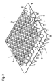
- the receiving device 2 together with the syringe bodies 3 is again shown separately.
- the syringe body 3 cooperate in a form-fitting manner approximately in its middle region with the receptacles 4 of the receiving device 2.
- the syringe bodies 3 are arranged in the receiving device 2 in a plurality of rows, wherein the individual rows have an offset from each other and wherein the syringe body 3 are arranged within each row in each case uniformly spaced.
- a device 10 according to the invention for the removal of syringe bodies 3 is shown.
- the device 10 is in this case in particular part of a packaging system 100, which is otherwise not shown, which has a plurality of processing stations, likewise not shown, on which the syringe bodies 3 are subjected to a series of processing or treatment steps which serve to supply the syringe bodies 3 fill and close.
- the syringe body 3 are filled in particular with a liquid pharmaceuticals, which in each case must be metered as accurately as possible.
- it is essential that the syringe bodies 3 are carefully closed in order to prevent the entry, for example, of germs or the like into the filled syringe body 3.
- the device 10 closes in particular at the end the actual packaging system 100 at.
- the device 10 can also expressly serve to remove syringe bodies 3 only for checking purposes, even if they have not previously been classified as potentially defective. In the following, however, the sake of simplicity of potentially defective syringe bodies 3 is spoken.
- the packaging system 100 has a control device 110 which detects and stores all potential errors which have occurred at the individual syringe bodies 3 during the production process.
- the control device 110 of the packaging system 100 is in this case connected to a control device 11 of the device 10.
- the packaging system 100 transmitted data on potentially defective syringe body 3 to the controller 11 of the device 10.
- the device 10 has a frame or a tabletop 12. Along one longitudinal side of the table top 12 extends a first conveying or transporting device 15, which by way of example has two conveyor belts 16 and 17 spaced parallel to one another, on which the transport containers 1 are continuously conveyed by frictional engagement.
- a first conveying or transporting device 15 which by way of example has two conveyor belts 16 and 17 spaced parallel to one another, on which the transport containers 1 are continuously conveyed by frictional engagement.
- the arrow 18 ( Fig. 3 ) designates the conveying direction of the transport container 1 between an inlet region 19 of the device 10 and an outlet region 20 of the device 10.
- the first transport device 15 interacts with a second transport device 23 via a first transfer unit 22.
- the second transport device 23 comprises an outfeed belt 24, which is arranged transversely to the first transport device 15 at the end of the table top 12 near the exit region 20.
- Parallel to the first transport device 15, a further conveyor belt 26 is arranged, which is also part of the second transport device 23.
- the conveyor belt 26 extends almost over the entire length of the device 10 and has at its end a again at right angles to the conveyor belt 26 arranged overthrust unit 27.
- a second shift unit 28 is arranged in alignment with the conveyor belt 26 in the region of the discharge belt 24.
- a plurality of movable up and down blocking elements 29 are arranged, which serve to stop the movement of a transport container 1 on the transport devices 15 and 23.
- the so far designated and described transport devices 15 and 23 are already well known from the conveyor, so that its exact functioning will not be discussed in detail here.
- three cameras 31 to 33 are arranged on the table top 12 by way of example.
- each of the cameras 31 to 33 serves a code, for example, arranged on a side wall of the transport container 1 or there to arrange arranged sign (not shown) and compare with stored within the controller 11 of the device 10 information.
- the first camera 32 is provided for the identification of transported on the first transport means 15 transport containers 1, while the second camera 33 serves to control the imprint by a print head 34 on the transport container 1.
- An identification of transport containers located on the conveyor belt 26 is effected by the camera 31.
- the printhead 34 is furthermore arranged in the region of the conveyor belt 15, by means of which information which is captured by the cameras 31 to 33, either to update, or new information eg by applying a printed image.
- a handling robot 35 is arranged, which at one end of an arm 36 has a pivotable in a vertical axis 37 Kombiwerkmaschine 38.
- the combination tool 38 in this case has a block or elongated shape, wherein on the one side of the combination tool 38 a plurality of gripping units 39 is arranged, while on the gripping units 39 opposite side of the combination tool 38 at one end region, a single gripping tool 41 is arranged , While a complete row of syringe bodies 3 can be removed from the receiving device 2 or a subset thereof with the gripping units 39, the gripping tool 41 serves to remove a single syringe body 3 from the receiving device 2.
- a lifting unit 43 for lifting a complete series of syringe bodies 3 from the receiving device 2 at.
- a lifting device 45 which is also viewed in the conveying direction, adjoins this lifting device 43 with a transport frame 46.
- a complete receiving device 2 can be removed from the transport container 1 and placed on the transport frame 46.
- the transport frame 46 in turn guides the isolated receiving device 2 into the region of the lifting unit 43.
- testing devices in particular weighing devices, may be arranged in the region of the handling robot 35 in order to check individual or several syringe bodies 3 with regard to the correct filling quantity.
- the device 10 described so far operates as follows: From the control device 110 of the packaging installation 100, the data is transmitted to the control device 11 of the device 10 with regard to potentially defective syringe bodies 3. In particular, in this case the data or an image of the identification feature printed on the transport container 1 is transmitted, which indicates which transport container 1 and which syringe bodies 3 arranged in the transport container 1 are potentially defective.
- the transport container 1 subsequently arrives at the print head 34 in order to optionally apply information to the transport container 1 by means of this. If the imprint is subsequently confirmed to be readable by the camera 33, there is no overtravel by the first transfer unit 22 on the discharge belt 24. Rather, the blocking elements 29 allow the transport container 1 to pass onto a roller belt 49, for example.
- the transport container 1 is a transport container 1 which contains potentially defective syringe bodies 3, or if the syringe body 3 is to be checked, or if it could not be identified or the identification imprint is incorrect, the relevant transport container will become 1 pushed by the first transport device 15 on the discharge belt 24. If the transport container 1 has been identified (And are potentially erroneous syringe body 3 refer to it or perform a test), the transport container 1 is pushed over by the second oversize unit 28 on Ausschleusband 24 on the conveyor belt 26. Otherwise, the blocking elements 29 allow the transport container 1 to pass, so that it is completely discharged. On the conveyor belt 26, the transport container 1 passes for re-identification by means of the camera 31.
- the corresponding transport container 1 is again identified to ensure that it is the transport container 1 to that transport container 1, which already with the camera 32 as potentially defective Syringe body 3 containing transport container 1 has been identified.
- the receiving device 2 reaches the transport frame 46.
- the transport frame 46 conveys the removed receiving device 2 in the region of the lifting unit 43, where the corresponding row of syringe bodies 3 is lifted out of the receiving device 2, to subsequently by means of the handling robot 35 and of the combination tool 38 to remove the potentially defective syringe body 3.
- the or the potentially defective syringe body 3 are checked on a test device, not shown, and are transferred to the detection of an error or the relevant syringe body 3 in the separation vessel 47.
- the receiving device 2 thus treated can then be inserted into the transport container 1 again by means of the transport frame 46 and the lifting device 45, whereupon the relevant transport container 1 is then pushed back into the production flow or into a gap on the first transport device 15 by means of the pushing unit 27.
- the device 10 described so far can be modified or modified in many ways.
- the device 10 is not limited to the use of the described transport devices 15 and 23, but may also have differently designed transport devices. It is only essential that in addition to the main conveyor for the transport container 1 a diversion in the manner of a "bypass" is created, which serves the control and discharge of potentially defective or to be checked syringe bodies 3, wherein instead of syringe bodies 3, of course, other containers can be processed ,
- a diversion in the manner of a "bypass" is created, which serves the control and discharge of potentially defective or to be checked syringe bodies 3, wherein instead of syringe bodies 3, of course, other containers can be processed .
- By means of a modified arrangement of the cameras 31 to 33 or other suitable identification devices it is possible to detect the transport containers 1 independently of the location of an identification feature. It is also conceivable to arrange the print head 34 in such a way that a jam pressure is possible on each side of the transport container 1.
Claims (9)
- Dispositif (10) pour l'extraction de contenants (3), en particulier de contenants pharmaceutiques (3), à partir d'un premier dispositif de transport (15) transportant les contenants (3) dans des contenants de transport (1), comprenant un premier dispositif d'identification (32) disposé sur la voie de transport du premier dispositif de transport (15) pour l'identification des contenants de transport (1), caractérisé en ce que le dispositif comprend un dispositif de décharge (24) disposé en aval du premier dispositif d'identification (32), qui transfère un contenant de transport (1) à un deuxième dispositif de transport (23), sur la section de transport duquel est disposé un dispositif d'extraction (35) pour l'extraction d'au moins un contenant (3), et un dispositif d'amenée (27) pour réintroduire le contenant de transport (1) dans le premier dispositif de transport (15).
- Dispositif selon la revendication 1,
caractérisé en ce
qu'un dispositif (45, 46) pour extraire et transporter hors du contenant de transport (1) un dispositif de réception (2) pour une pluralité de contenants (3) disposés dans des logements (4) est disposé dans la région du deuxième dispositif de transport (23), lequel achemine le dispositif de réception (2) pour l'extraction d'au moins un contenant (3) hors du contenant de transport (1) jusqu'au dispositif d'extraction (43). - Dispositif selon l'une quelconque des revendications 1 à 2,
caractérisé en ce que
dans la région du deuxième dispositif de transport (23) est disposé un deuxième dispositif d'identification (31) et en ce que le deuxième dispositif d'identification (31) coopère avec le dispositif d'extraction (35) pour extraire au moins un contenant (3). - Dispositif selon l'une quelconque des revendications 1 à 3,
caractérisé en ce
qu'un dispositif de décharge (28) pour des contenants de transport (1) est disposé dans la région du deuxième dispositif de transport (23). - Dispositif selon l'une quelconque des revendications 1 à 4,
caractérisé en ce
qu'un dispositif de contrôle, en particulier un dispositif de pesée, est disposé dans la région du deuxième dispositif de transport (23). - Dispositif selon l'une quelconque des revendications 1 à 5,
caractérisé en ce que
le premier et le deuxième dispositif de transport (15, 23) sont réalisés à chaque fois sous forme de bandes transporteuses. - Dispositif selon l'une quelconque des revendications 1 à 6,
caractérisé en ce que
le dispositif (10) présente seulement un dispositif de décharge unique (49). - Dispositif selon l'une quelconque des revendications 1 ou 7,
caractérisé en ce
qu'un dispositif de caractérisation (34) pour les contenants de transport (1) transportés dans la région du premier dispositif de transport (15) est disposé dans la région du premier dispositif de transport (15). - Installation d'emballage (100) comprenant un dispositif (10) selon l'une quelconque des revendications 1 à 8,
caractérisée en ce que
le premier dispositif d'identification (31) du dispositif (10) est accouplé au moins de manière indirecte à un dispositif de commande (110) de l'installation d'emballage (100).
Applications Claiming Priority (2)
| Application Number | Priority Date | Filing Date | Title |
|---|---|---|---|
| DE102009046662A DE102009046662A1 (de) | 2009-11-12 | 2009-11-12 | Vorrichtung zur Entnahme von Behältern |
| PCT/EP2010/064627 WO2011057862A1 (fr) | 2009-11-12 | 2010-10-01 | Dispositif de reprise de contenants |
Publications (2)
| Publication Number | Publication Date |
|---|---|
| EP2499501A1 EP2499501A1 (fr) | 2012-09-19 |
| EP2499501B1 true EP2499501B1 (fr) | 2013-07-03 |
Family
ID=43416615
Family Applications (1)
| Application Number | Title | Priority Date | Filing Date |
|---|---|---|---|
| EP10762647.5A Active EP2499501B1 (fr) | 2009-11-12 | 2010-10-01 | Dispositif d'extraction de contenants et machine d'emballage |
Country Status (6)
| Country | Link |
|---|---|
| US (1) | US20130015108A1 (fr) |
| EP (1) | EP2499501B1 (fr) |
| CN (1) | CN102612654B (fr) |
| DE (1) | DE102009046662A1 (fr) |
| IN (1) | IN2012DN02146A (fr) |
| WO (1) | WO2011057862A1 (fr) |
Cited By (2)
| Publication number | Priority date | Publication date | Assignee | Title |
|---|---|---|---|---|
| CH712191A1 (de) * | 2016-03-04 | 2017-09-15 | Wrh Walter Reist Holding Ag | Fördereinrichtung mit einer Förderkette sowie mit einer Mehrzahl von an der Förderkette angebrachten Fördergutbehältern. |
| DE102019129329A1 (de) * | 2019-10-30 | 2021-05-06 | Ma Micro Automation Gmbh | Handhabungsvorrichtung und Entnahmestation |
Families Citing this family (4)
| Publication number | Priority date | Publication date | Assignee | Title |
|---|---|---|---|---|
| DE102016209710A1 (de) * | 2016-06-02 | 2017-12-07 | Robert Bosch Gmbh | Vorrichtung und Verfahren zur Inspektion von Behältnissen |
| US20200338258A1 (en) * | 2017-11-08 | 2020-10-29 | Windgap Medical, Inc. | System and method for providing and assembling an auto-injector |
| CN109436801A (zh) * | 2018-11-29 | 2019-03-08 | 杭州捷能科技有限公司 | 一种零件自动上料装置及零件自动上料方法 |
| DE102019201950A1 (de) | 2019-02-14 | 2020-08-20 | Syntegon Technology Gmbh | Vorrichtung und Verfahren zum Einlegen von Mischkugeln in pharmazeutische Behältnisse |
Family Cites Families (21)
| Publication number | Priority date | Publication date | Assignee | Title |
|---|---|---|---|---|
| DE3408081A1 (de) * | 1984-03-05 | 1985-09-19 | Siemens AG, 1000 Berlin und 8000 München | Kommissioniereinrichtung |
| US5578331A (en) * | 1994-06-10 | 1996-11-26 | Vision Products, Inc. | Automated apparatus for preparing contact lenses for inspection and packaging |
| US5623415A (en) * | 1995-02-16 | 1997-04-22 | Smithkline Beecham Corporation | Automated sampling and testing of biological materials |
| DE19604100C2 (de) * | 1996-02-06 | 1997-12-18 | Bosch Gmbh Robert | Vorrichtung zum Handhaben von in einem nach oben offenen Behälter angeordneten, befüllbaren, rohrförmigen Gegenständen |
| JP3031242B2 (ja) * | 1996-05-20 | 2000-04-10 | 株式会社日立製作所 | 多項目分析装置 |
| WO1998001760A2 (fr) * | 1996-07-05 | 1998-01-15 | Beckman Coulter, Inc. | Systeme automatise de traitement d'echantillons |
| JP3336894B2 (ja) * | 1997-01-29 | 2002-10-21 | 株式会社日立製作所 | 自動分析装置 |
| DE19819812C2 (de) * | 1998-05-04 | 2000-11-02 | Olympus Diagnostica Gmbh | Laborprimärprobenverteiler mit einer Verteileinrichtung |
| DE19819813C2 (de) * | 1998-05-04 | 2000-11-02 | Olympus Diagnostica Gmbh | Verwendung eines Laborprimärprobenverteilers zum Archivieren |
| JP4136187B2 (ja) * | 1999-05-14 | 2008-08-20 | シスメックス株式会社 | 検体移し替え装置 |
| DE10204247B4 (de) * | 2002-02-02 | 2007-06-14 | Adam Opel Ag | Verfahren zum Aus- und Einschleusen eines Bauteils aus und in ein Transportsystem und Einrichtung dazu |
| FR2867861B1 (fr) * | 2004-03-16 | 2006-07-14 | Abx Sa | Dispositif pour l'approvisionnement d'analyseurs sur sang total |
| DE102004035061A1 (de) * | 2004-07-20 | 2006-02-16 | Bausch + Ströbel Maschinenfabrik Ilshofen GmbH + Co. KG | Vorrichtung und Verfahren zum dosierten Befüllen von Gefäßen, insbesondere Spritzenkörper |
| EP1630550A1 (fr) * | 2004-08-27 | 2006-03-01 | Moller & Devicon A/S | Procédé et appareil pour la détection de corps étrangers ou de défauts dans une multitude de conteneurs remplis |
| DE202004018512U1 (de) * | 2004-10-08 | 2005-09-22 | Kuka Schweissanlagen Gmbh | Bearbeitungsanlage |
| CH702317B1 (it) * | 2007-08-02 | 2011-06-15 | Stevanato Group Internat As | Struttura di confezione di flaconi in vetro ad uso farmaceutico. |
| DE102007048684B4 (de) * | 2007-10-10 | 2010-09-09 | Polysius Ag | Laborsystem |
| JP5198094B2 (ja) * | 2008-03-07 | 2013-05-15 | シスメックス株式会社 | 分析装置 |
| US8822224B2 (en) * | 2008-07-02 | 2014-09-02 | Prairie Ventures Llc | Method for automatic testing of anatomical laboratory specimens |
| EP2148205B1 (fr) * | 2008-07-25 | 2013-01-02 | F. Hoffmann-La Roche AG | Procédé et système de laboratoire pour manipuler des tubes d'échantillons et unité d'analyse d'images |
| JP5378859B2 (ja) * | 2009-03-30 | 2013-12-25 | シスメックス株式会社 | 検体検査システム |
-
2009
- 2009-11-12 DE DE102009046662A patent/DE102009046662A1/de not_active Withdrawn
-
2010
- 2010-10-01 IN IN2146DEN2012 patent/IN2012DN02146A/en unknown
- 2010-10-01 CN CN201080051075.2A patent/CN102612654B/zh active Active
- 2010-10-01 EP EP10762647.5A patent/EP2499501B1/fr active Active
- 2010-10-01 US US13/509,680 patent/US20130015108A1/en not_active Abandoned
- 2010-10-01 WO PCT/EP2010/064627 patent/WO2011057862A1/fr active Application Filing
Cited By (3)
| Publication number | Priority date | Publication date | Assignee | Title |
|---|---|---|---|---|
| CH712191A1 (de) * | 2016-03-04 | 2017-09-15 | Wrh Walter Reist Holding Ag | Fördereinrichtung mit einer Förderkette sowie mit einer Mehrzahl von an der Förderkette angebrachten Fördergutbehältern. |
| US10011430B2 (en) | 2016-03-04 | 2018-07-03 | Wrh Walter Reist Holding Ag | Conveying device with a conveying chain |
| DE102019129329A1 (de) * | 2019-10-30 | 2021-05-06 | Ma Micro Automation Gmbh | Handhabungsvorrichtung und Entnahmestation |
Also Published As
| Publication number | Publication date |
|---|---|
| CN102612654B (zh) | 2016-07-06 |
| CN102612654A (zh) | 2012-07-25 |
| US20130015108A1 (en) | 2013-01-17 |
| DE102009046662A1 (de) | 2011-05-19 |
| WO2011057862A1 (fr) | 2011-05-19 |
| EP2499501A1 (fr) | 2012-09-19 |
| IN2012DN02146A (fr) | 2015-08-07 |
Similar Documents
| Publication | Publication Date | Title |
|---|---|---|
| EP2499501B1 (fr) | Dispositif d'extraction de contenants et machine d'emballage | |
| EP2280873B1 (fr) | Remplisseuse et capsuleuse de contenants | |
| EP2448820B1 (fr) | Dispositif pour remplir et fermer des contenants pharmaceutiques | |
| EP2570350B1 (fr) | Procédé et dispositif de remplissage et de fermeture d'objets pharmaceutiques | |
| EP2799374B1 (fr) | Système et procédé de sortie de récipients de boisson d'un dispositif de transport se déplaçant | |
| EP3342719B1 (fr) | Dispositif et procédé destinés au remplissage de récipients emboîtés | |
| EP2698213B1 (fr) | Dispositif de marquage de récipients, dispositif de traitement de récipients et procédé de marquage de récipients | |
| DE102004023473B4 (de) | Verpackungsmaschine und Verfahren zum Zuführen von Behältern in einer Verpackungsmaschine | |
| EP2345587A1 (fr) | Installation d'emballage dotée d'une station d'évacuation | |
| EP2560602B1 (fr) | Dispositif pour le remplissage et la fermeture de capsules remplies d'au moins une matière de remplissage | |
| DE3324449C2 (fr) | ||
| WO2020058135A1 (fr) | Procédé et dispositif d'acheminement de produits d'un premier processus vers un second processus dans une installation d'emballage | |
| EP2006204B1 (fr) | Installation destinée à la mise en bouteille de produits pharmaceutiques dans des récipients de types bouteilles | |
| DE102014001741A1 (de) | Etikettiereinrichtung, Etikettiersystem und Verfahren zum Bestücken eines Produkts mit einem Etikett | |
| WO2019048368A1 (fr) | Dispositif et procédé d'orientation de lots de produits | |
| DE102015203060A1 (de) | Inspektionsvorrichtung zum Inspizieren von Behältern | |
| EP1655227B1 (fr) | Dispositif pour déballer de conteneurs hors de la caisse de transport | |
| EP3380420B1 (fr) | Installation et procédé permettant de séparer et/ou de contrôler des contenants | |
| EP3678792B1 (fr) | Dispositif et procédé de rejet des récipients incorrectement imprimés dans une presse directe | |
| EP3789129A1 (fr) | Procédé et appareil de surveillance du fonctionnement d'une machine de nettoyage des récipients | |
| EP3463695B1 (fr) | Dispositif et procédé d'inspection de récipients | |
| DE102018128498A1 (de) | Verfahren zur Bauteilverfolgung | |
| DE102021127564B3 (de) | Vorrichtung und Verfahren zum Verschließen von Behältnissen mit Verschlüssen | |
| EP3733342B1 (fr) | Dispositif de transport | |
| DE102017108903B4 (de) | Behandlungsvorrichtung sowie Behälterbehandlungsmaschine |
Legal Events
| Date | Code | Title | Description |
|---|---|---|---|
| PUAI | Public reference made under article 153(3) epc to a published international application that has entered the european phase |
Free format text: ORIGINAL CODE: 0009012 |
|
| 17P | Request for examination filed |
Effective date: 20120612 |
|
| AK | Designated contracting states |
Kind code of ref document: A1 Designated state(s): AL AT BE BG CH CY CZ DE DK EE ES FI FR GB GR HR HU IE IS IT LI LT LU LV MC MK MT NL NO PL PT RO RS SE SI SK SM TR |
|
| DAX | Request for extension of the european patent (deleted) | ||
| GRAP | Despatch of communication of intention to grant a patent |
Free format text: ORIGINAL CODE: EPIDOSNIGR1 |
|
| INTG | Intention to grant announced |
Effective date: 20130408 |
|
| GRAS | Grant fee paid |
Free format text: ORIGINAL CODE: EPIDOSNIGR3 |
|
| GRAA | (expected) grant |
Free format text: ORIGINAL CODE: 0009210 |
|
| AK | Designated contracting states |
Kind code of ref document: B1 Designated state(s): AL AT BE BG CH CY CZ DE DK EE ES FI FR GB GR HR HU IE IS IT LI LT LU LV MC MK MT NL NO PL PT RO RS SE SI SK SM TR |
|
| REG | Reference to a national code |
Ref country code: GB Ref legal event code: FG4D Free format text: NOT ENGLISH |
|
| REG | Reference to a national code |
Ref country code: AT Ref legal event code: REF Ref document number: 620061 Country of ref document: AT Kind code of ref document: T Effective date: 20130715 Ref country code: CH Ref legal event code: EP |
|
| REG | Reference to a national code |
Ref country code: IE Ref legal event code: FG4D Free format text: LANGUAGE OF EP DOCUMENT: GERMAN |
|
| REG | Reference to a national code |
Ref country code: DE Ref legal event code: R096 Ref document number: 502010003913 Country of ref document: DE Effective date: 20130829 |
|
| PG25 | Lapsed in a contracting state [announced via postgrant information from national office to epo] |
Ref country code: SI Free format text: LAPSE BECAUSE OF FAILURE TO SUBMIT A TRANSLATION OF THE DESCRIPTION OR TO PAY THE FEE WITHIN THE PRESCRIBED TIME-LIMIT Effective date: 20130703 |
|
| REG | Reference to a national code |
Ref country code: NL Ref legal event code: VDEP Effective date: 20130703 |
|
| REG | Reference to a national code |
Ref country code: LT Ref legal event code: MG4D |
|
| PG25 | Lapsed in a contracting state [announced via postgrant information from national office to epo] |
Ref country code: CY Free format text: LAPSE BECAUSE OF FAILURE TO SUBMIT A TRANSLATION OF THE DESCRIPTION OR TO PAY THE FEE WITHIN THE PRESCRIBED TIME-LIMIT Effective date: 20130911 Ref country code: NO Free format text: LAPSE BECAUSE OF FAILURE TO SUBMIT A TRANSLATION OF THE DESCRIPTION OR TO PAY THE FEE WITHIN THE PRESCRIBED TIME-LIMIT Effective date: 20131003 Ref country code: LT Free format text: LAPSE BECAUSE OF FAILURE TO SUBMIT A TRANSLATION OF THE DESCRIPTION OR TO PAY THE FEE WITHIN THE PRESCRIBED TIME-LIMIT Effective date: 20130703 Ref country code: IS Free format text: LAPSE BECAUSE OF FAILURE TO SUBMIT A TRANSLATION OF THE DESCRIPTION OR TO PAY THE FEE WITHIN THE PRESCRIBED TIME-LIMIT Effective date: 20131103 Ref country code: SE Free format text: LAPSE BECAUSE OF FAILURE TO SUBMIT A TRANSLATION OF THE DESCRIPTION OR TO PAY THE FEE WITHIN THE PRESCRIBED TIME-LIMIT Effective date: 20130703 Ref country code: HR Free format text: LAPSE BECAUSE OF FAILURE TO SUBMIT A TRANSLATION OF THE DESCRIPTION OR TO PAY THE FEE WITHIN THE PRESCRIBED TIME-LIMIT Effective date: 20130703 Ref country code: PT Free format text: LAPSE BECAUSE OF FAILURE TO SUBMIT A TRANSLATION OF THE DESCRIPTION OR TO PAY THE FEE WITHIN THE PRESCRIBED TIME-LIMIT Effective date: 20131104 |
|
| PG25 | Lapsed in a contracting state [announced via postgrant information from national office to epo] |
Ref country code: NL Free format text: LAPSE BECAUSE OF FAILURE TO SUBMIT A TRANSLATION OF THE DESCRIPTION OR TO PAY THE FEE WITHIN THE PRESCRIBED TIME-LIMIT Effective date: 20130703 Ref country code: FI Free format text: LAPSE BECAUSE OF FAILURE TO SUBMIT A TRANSLATION OF THE DESCRIPTION OR TO PAY THE FEE WITHIN THE PRESCRIBED TIME-LIMIT Effective date: 20130703 Ref country code: GR Free format text: LAPSE BECAUSE OF FAILURE TO SUBMIT A TRANSLATION OF THE DESCRIPTION OR TO PAY THE FEE WITHIN THE PRESCRIBED TIME-LIMIT Effective date: 20131004 Ref country code: PL Free format text: LAPSE BECAUSE OF FAILURE TO SUBMIT A TRANSLATION OF THE DESCRIPTION OR TO PAY THE FEE WITHIN THE PRESCRIBED TIME-LIMIT Effective date: 20130703 Ref country code: ES Free format text: LAPSE BECAUSE OF FAILURE TO SUBMIT A TRANSLATION OF THE DESCRIPTION OR TO PAY THE FEE WITHIN THE PRESCRIBED TIME-LIMIT Effective date: 20131014 Ref country code: LV Free format text: LAPSE BECAUSE OF FAILURE TO SUBMIT A TRANSLATION OF THE DESCRIPTION OR TO PAY THE FEE WITHIN THE PRESCRIBED TIME-LIMIT Effective date: 20130703 |
|
| PG25 | Lapsed in a contracting state [announced via postgrant information from national office to epo] |
Ref country code: CY Free format text: LAPSE BECAUSE OF FAILURE TO SUBMIT A TRANSLATION OF THE DESCRIPTION OR TO PAY THE FEE WITHIN THE PRESCRIBED TIME-LIMIT Effective date: 20130703 |
|
| BERE | Be: lapsed |
Owner name: ROBERT BOSCH G.M.B.H. Effective date: 20131031 |
|
| PG25 | Lapsed in a contracting state [announced via postgrant information from national office to epo] |
Ref country code: CZ Free format text: LAPSE BECAUSE OF FAILURE TO SUBMIT A TRANSLATION OF THE DESCRIPTION OR TO PAY THE FEE WITHIN THE PRESCRIBED TIME-LIMIT Effective date: 20130703 Ref country code: DK Free format text: LAPSE BECAUSE OF FAILURE TO SUBMIT A TRANSLATION OF THE DESCRIPTION OR TO PAY THE FEE WITHIN THE PRESCRIBED TIME-LIMIT Effective date: 20130703 Ref country code: SK Free format text: LAPSE BECAUSE OF FAILURE TO SUBMIT A TRANSLATION OF THE DESCRIPTION OR TO PAY THE FEE WITHIN THE PRESCRIBED TIME-LIMIT Effective date: 20130703 Ref country code: RO Free format text: LAPSE BECAUSE OF FAILURE TO SUBMIT A TRANSLATION OF THE DESCRIPTION OR TO PAY THE FEE WITHIN THE PRESCRIBED TIME-LIMIT Effective date: 20130703 Ref country code: EE Free format text: LAPSE BECAUSE OF FAILURE TO SUBMIT A TRANSLATION OF THE DESCRIPTION OR TO PAY THE FEE WITHIN THE PRESCRIBED TIME-LIMIT Effective date: 20130703 |
|
| PLBE | No opposition filed within time limit |
Free format text: ORIGINAL CODE: 0009261 |
|
| STAA | Information on the status of an ep patent application or granted ep patent |
Free format text: STATUS: NO OPPOSITION FILED WITHIN TIME LIMIT |
|
| PG25 | Lapsed in a contracting state [announced via postgrant information from national office to epo] |
Ref country code: MC Free format text: LAPSE BECAUSE OF FAILURE TO SUBMIT A TRANSLATION OF THE DESCRIPTION OR TO PAY THE FEE WITHIN THE PRESCRIBED TIME-LIMIT Effective date: 20130703 |
|
| 26N | No opposition filed |
Effective date: 20140404 |
|
| REG | Reference to a national code |
Ref country code: DE Ref legal event code: R097 Ref document number: 502010003913 Country of ref document: DE Effective date: 20140404 |
|
| REG | Reference to a national code |
Ref country code: IE Ref legal event code: MM4A |
|
| REG | Reference to a national code |
Ref country code: FR Ref legal event code: ST Effective date: 20140630 |
|
| PG25 | Lapsed in a contracting state [announced via postgrant information from national office to epo] |
Ref country code: FR Free format text: LAPSE BECAUSE OF NON-PAYMENT OF DUE FEES Effective date: 20131031 |
|
| PG25 | Lapsed in a contracting state [announced via postgrant information from national office to epo] |
Ref country code: BE Free format text: LAPSE BECAUSE OF NON-PAYMENT OF DUE FEES Effective date: 20131031 |
|
| PG25 | Lapsed in a contracting state [announced via postgrant information from national office to epo] |
Ref country code: IE Free format text: LAPSE BECAUSE OF NON-PAYMENT OF DUE FEES Effective date: 20131001 |
|
| PG25 | Lapsed in a contracting state [announced via postgrant information from national office to epo] |
Ref country code: SM Free format text: LAPSE BECAUSE OF FAILURE TO SUBMIT A TRANSLATION OF THE DESCRIPTION OR TO PAY THE FEE WITHIN THE PRESCRIBED TIME-LIMIT Effective date: 20130703 |
|
| REG | Reference to a national code |
Ref country code: CH Ref legal event code: PL |
|
| GBPC | Gb: european patent ceased through non-payment of renewal fee |
Effective date: 20141001 |
|
| PG25 | Lapsed in a contracting state [announced via postgrant information from national office to epo] |
Ref country code: HU Free format text: LAPSE BECAUSE OF FAILURE TO SUBMIT A TRANSLATION OF THE DESCRIPTION OR TO PAY THE FEE WITHIN THE PRESCRIBED TIME-LIMIT; INVALID AB INITIO Effective date: 20101001 Ref country code: CH Free format text: LAPSE BECAUSE OF NON-PAYMENT OF DUE FEES Effective date: 20141031 Ref country code: RS Free format text: LAPSE BECAUSE OF FAILURE TO SUBMIT A TRANSLATION OF THE DESCRIPTION OR TO PAY THE FEE WITHIN THE PRESCRIBED TIME-LIMIT Effective date: 20131003 Ref country code: LU Free format text: LAPSE BECAUSE OF NON-PAYMENT OF DUE FEES Effective date: 20131001 Ref country code: BG Free format text: LAPSE BECAUSE OF FAILURE TO SUBMIT A TRANSLATION OF THE DESCRIPTION OR TO PAY THE FEE WITHIN THE PRESCRIBED TIME-LIMIT Effective date: 20130703 Ref country code: GB Free format text: LAPSE BECAUSE OF NON-PAYMENT OF DUE FEES Effective date: 20141001 Ref country code: LI Free format text: LAPSE BECAUSE OF NON-PAYMENT OF DUE FEES Effective date: 20141031 Ref country code: MK Free format text: LAPSE BECAUSE OF FAILURE TO SUBMIT A TRANSLATION OF THE DESCRIPTION OR TO PAY THE FEE WITHIN THE PRESCRIBED TIME-LIMIT Effective date: 20130703 |
|
| PG25 | Lapsed in a contracting state [announced via postgrant information from national office to epo] |
Ref country code: MT Free format text: LAPSE BECAUSE OF FAILURE TO SUBMIT A TRANSLATION OF THE DESCRIPTION OR TO PAY THE FEE WITHIN THE PRESCRIBED TIME-LIMIT Effective date: 20130703 |
|
| PG25 | Lapsed in a contracting state [announced via postgrant information from national office to epo] |
Ref country code: TR Free format text: LAPSE BECAUSE OF FAILURE TO SUBMIT A TRANSLATION OF THE DESCRIPTION OR TO PAY THE FEE WITHIN THE PRESCRIBED TIME-LIMIT Effective date: 20130703 |
|
| REG | Reference to a national code |
Ref country code: AT Ref legal event code: MM01 Ref document number: 620061 Country of ref document: AT Kind code of ref document: T Effective date: 20151001 |
|
| PG25 | Lapsed in a contracting state [announced via postgrant information from national office to epo] |
Ref country code: AT Free format text: LAPSE BECAUSE OF NON-PAYMENT OF DUE FEES Effective date: 20151001 |
|
| PG25 | Lapsed in a contracting state [announced via postgrant information from national office to epo] |
Ref country code: AL Free format text: LAPSE BECAUSE OF FAILURE TO SUBMIT A TRANSLATION OF THE DESCRIPTION OR TO PAY THE FEE WITHIN THE PRESCRIBED TIME-LIMIT Effective date: 20130703 |
|
| REG | Reference to a national code |
Ref country code: DE Ref legal event code: R082 Ref document number: 502010003913 Country of ref document: DE Representative=s name: DREISS PATENTANWAELTE PARTG MBB, DE Ref country code: DE Ref legal event code: R081 Ref document number: 502010003913 Country of ref document: DE Owner name: SYNTEGON TECHNOLOGY GMBH, DE Free format text: FORMER OWNER: ROBERT BOSCH GMBH, 70469 STUTTGART, DE Ref country code: DE Ref legal event code: R081 Ref document number: 502010003913 Country of ref document: DE Owner name: SYNTEGON TECHNOLOGY GMBH, DE Free format text: FORMER OWNER: ROBERT BOSCH PACKAGING TECHNOLOGY GMBH, 71332 WAIBLINGEN, DE |
|
| PGFP | Annual fee paid to national office [announced via postgrant information from national office to epo] |
Ref country code: IT Payment date: 20231031 Year of fee payment: 14 Ref country code: DE Payment date: 20231018 Year of fee payment: 14 |