EP2499501B1 - Device for extracting containers and packaging machine - Google Patents
Device for extracting containers and packaging machine Download PDFInfo
- Publication number
- EP2499501B1 EP2499501B1 EP10762647.5A EP10762647A EP2499501B1 EP 2499501 B1 EP2499501 B1 EP 2499501B1 EP 10762647 A EP10762647 A EP 10762647A EP 2499501 B1 EP2499501 B1 EP 2499501B1
- Authority
- EP
- European Patent Office
- Prior art keywords
- containers
- transporting
- transport
- container
- region
- Prior art date
- Legal status (The legal status is an assumption and is not a legal conclusion. Google has not performed a legal analysis and makes no representation as to the accuracy of the status listed.)
- Active
Links
- 238000004806 packaging method and process Methods 0.000 title claims description 18
- 238000012546 transfer Methods 0.000 claims abstract description 6
- 238000012360 testing method Methods 0.000 claims description 8
- 238000009434 installation Methods 0.000 claims description 7
- 238000007599 discharging Methods 0.000 claims description 4
- 238000005303 weighing Methods 0.000 claims description 4
- 230000002950 deficient Effects 0.000 description 17
- 238000004519 manufacturing process Methods 0.000 description 10
- 238000012545 processing Methods 0.000 description 7
- 230000000903 blocking effect Effects 0.000 description 5
- 238000011161 development Methods 0.000 description 2
- 230000018109 developmental process Effects 0.000 description 2
- 239000003814 drug Substances 0.000 description 2
- 239000007788 liquid Substances 0.000 description 2
- 238000000034 method Methods 0.000 description 2
- 238000012544 monitoring process Methods 0.000 description 2
- 238000012552 review Methods 0.000 description 2
- 238000004458 analytical method Methods 0.000 description 1
- 244000052616 bacterial pathogen Species 0.000 description 1
- 230000007547 defect Effects 0.000 description 1
- 230000001419 dependent effect Effects 0.000 description 1
- 238000001514 detection method Methods 0.000 description 1
- 238000005516 engineering process Methods 0.000 description 1
- 239000000463 material Substances 0.000 description 1
- 238000009512 pharmaceutical packaging Methods 0.000 description 1
- 238000002360 preparation method Methods 0.000 description 1
- 238000007789 sealing Methods 0.000 description 1
- 238000000926 separation method Methods 0.000 description 1
Images


Classifications
-
- B—PERFORMING OPERATIONS; TRANSPORTING
- B65—CONVEYING; PACKING; STORING; HANDLING THIN OR FILAMENTARY MATERIAL
- B65G—TRANSPORT OR STORAGE DEVICES, e.g. CONVEYORS FOR LOADING OR TIPPING, SHOP CONVEYOR SYSTEMS OR PNEUMATIC TUBE CONVEYORS
- B65G37/00—Combinations of mechanical conveyors of the same kind, or of different kinds, of interest apart from their application in particular machines or use in particular manufacturing processes
- B65G37/02—Flow-sheets for conveyor combinations in warehouses, magazines or workshops
-
- G—PHYSICS
- G01—MEASURING; TESTING
- G01N—INVESTIGATING OR ANALYSING MATERIALS BY DETERMINING THEIR CHEMICAL OR PHYSICAL PROPERTIES
- G01N35/00—Automatic analysis not limited to methods or materials provided for in any single one of groups G01N1/00 - G01N33/00; Handling materials therefor
- G01N35/02—Automatic analysis not limited to methods or materials provided for in any single one of groups G01N1/00 - G01N33/00; Handling materials therefor using a plurality of sample containers moved by a conveyor system past one or more treatment or analysis stations
- G01N35/04—Details of the conveyor system
- G01N2035/0401—Sample carriers, cuvettes or reaction vessels
- G01N2035/0418—Plate elements with several rows of samples
- G01N2035/0422—Plate elements with several rows of samples carried on a linear conveyor
-
- G—PHYSICS
- G01—MEASURING; TESTING
- G01N—INVESTIGATING OR ANALYSING MATERIALS BY DETERMINING THEIR CHEMICAL OR PHYSICAL PROPERTIES
- G01N35/00—Automatic analysis not limited to methods or materials provided for in any single one of groups G01N1/00 - G01N33/00; Handling materials therefor
- G01N35/02—Automatic analysis not limited to methods or materials provided for in any single one of groups G01N1/00 - G01N33/00; Handling materials therefor using a plurality of sample containers moved by a conveyor system past one or more treatment or analysis stations
- G01N35/04—Details of the conveyor system
- G01N2035/046—General conveyor features
- G01N2035/0465—Loading or unloading the conveyor
Definitions
- the invention relates to a device for removing containers and a packaging system with such a device.
- the pharmaceutical packaging industry it is known to process containers such as syringe bodies, vials or ampoules on combined filling and sealing systems.
- the pharmaceutical container for example, filled with a liquid pharmaceuticals, weighed and then sealed with a closure element.
- the containers continue to undergo various controls to ensure proper filling and proper closure of the containers. Should this lead to errors during the processing of the containers, it is necessary to discharge the containers at a suitable station.
- a handling device in which, in particular, syringe bodies can be removed from a receptacle individually or together, the receptacle having receptacles for the syringe bodies.
- DE 10 2007 048 684 A1 relates to a laboratory system which essentially comprises a transport device for samples, at least one treatment device for the preparation, analysis and / or processing of samples, at least one movable handling device for handling the samples in the region of a treatment device and a monitoring system accompanying the handling device for maintaining a Safety distance exists.
- the monitoring system is formed by a camera for generating distance images and / or a location system with at least one transmitter and at least one receiver, wherein the receiver is mounted on the movable transport device and is designed such that it generates an alarm signal when the at least one transmitter Minimum distance to the receiver is below.
- the invention has the object, an apparatus for removing containers in such a way that a running production or conveying process in the packaging plant is disturbed as little as possible.
- This object is achieved in a device for removing containers with the features of claim 1.
- the invention is based on the idea to transfer by a discharge device transport containers containing potentially defective container on a separate or separate from a first transport means second transport device. This makes it possible that the production or transport flow of transport containers on the first conveyor is not disturbed, i. subsequent transport containers are transported on with "good containers" without the respective transport containers being ejected or stopped.
- the checking of the containers in the transport container on the second transport device can, in principle, take any length, without resulting in disadvantages. In particular, relatively complex or time-consuming tests can be carried out on the containers.
- a device for removing and transporting a receiving device for a plurality of containers arranged in receptacles from the transport container is arranged, which supplies the receiving device for removing at least one container from the transport container of the removal device.
- a second identification device is arranged in the region of the second transport device and that the second identification device with the removal device for removal of at least one Container cooperates from the transport container. This ensures that only those containers are removed from the transport container, which were identified by means of the first and the second identification device as faulty.
- a discharge device for transport containers is arranged in the region of the second transport device.
- This discharge device serves to discharge transport containers, which are either discharged directly from the first conveyor, orfrequencyschleusen such transport containers, which are still identified as defective even after circulation on the second conveyor.
- a test device in particular a weighing device, to be arranged in the region of the second transport device.
- the containers which are previously identified as critical or faulty, or were selected by the operator or by the machine control purposefully or randomly, be checked by means of suitable testing equipment. In this way, the production steps of the packaging system can be checked or ensured that no containers are discharged, which are "good".
- a simple handling of the transport container on the first transport device and the second transport device is made possible if the two transport devices are each designed as conveyor belts on which the transport containers are conveyed by frictional engagement.
- Such transport devices are known in assembly technology or in manufacturing plants in a variety of ways and allow, for example by the use of transverse conveyor belts as well as in the conveying path of the transport container projecting deflection or blocking elements controlling the movement of the transport container.
- the device for removing containers according to the invention is preferably part of a packaging installation which has a plurality of processing stations.
- the device according to the invention preferably adjoins the end of the packaging installation, ie at this point all irregularities or defects in the containers ascertained during the production process of the containers are taken into account by discharging the corresponding containers from the packaging installation.
- the first identification device of the device is coupled to a control device of the packaging system.
- a transport container 1 which is also referred to in the pharmaceutical industry as a "tub” shown.
- the box-like transport container 1 serves to receive a receiving device 2, which is also referred to as a "nest".
- a receiving device 2 which is also referred to as a "nest”.
- a plurality of pharmaceutical containers, in particular syringe body 3, arrange or transport, with corresponding receptacles 4 are formed in the receiving device 2, which serve to receive the syringe body 3 positively.
- recesses 5, 6 which serve to cooperate with a removal device (which will be explained later), so that a removal or a raising and lowering of the receiving device 2 from the transport container 1 is enabled.
- the receiving device 2 together with the syringe bodies 3 is again shown separately.
- the syringe body 3 cooperate in a form-fitting manner approximately in its middle region with the receptacles 4 of the receiving device 2.
- the syringe bodies 3 are arranged in the receiving device 2 in a plurality of rows, wherein the individual rows have an offset from each other and wherein the syringe body 3 are arranged within each row in each case uniformly spaced.
- a device 10 according to the invention for the removal of syringe bodies 3 is shown.
- the device 10 is in this case in particular part of a packaging system 100, which is otherwise not shown, which has a plurality of processing stations, likewise not shown, on which the syringe bodies 3 are subjected to a series of processing or treatment steps which serve to supply the syringe bodies 3 fill and close.
- the syringe body 3 are filled in particular with a liquid pharmaceuticals, which in each case must be metered as accurately as possible.
- it is essential that the syringe bodies 3 are carefully closed in order to prevent the entry, for example, of germs or the like into the filled syringe body 3.
- the device 10 closes in particular at the end the actual packaging system 100 at.
- the device 10 can also expressly serve to remove syringe bodies 3 only for checking purposes, even if they have not previously been classified as potentially defective. In the following, however, the sake of simplicity of potentially defective syringe bodies 3 is spoken.
- the packaging system 100 has a control device 110 which detects and stores all potential errors which have occurred at the individual syringe bodies 3 during the production process.
- the control device 110 of the packaging system 100 is in this case connected to a control device 11 of the device 10.
- the packaging system 100 transmitted data on potentially defective syringe body 3 to the controller 11 of the device 10.
- the device 10 has a frame or a tabletop 12. Along one longitudinal side of the table top 12 extends a first conveying or transporting device 15, which by way of example has two conveyor belts 16 and 17 spaced parallel to one another, on which the transport containers 1 are continuously conveyed by frictional engagement.
- a first conveying or transporting device 15 which by way of example has two conveyor belts 16 and 17 spaced parallel to one another, on which the transport containers 1 are continuously conveyed by frictional engagement.
- the arrow 18 ( Fig. 3 ) designates the conveying direction of the transport container 1 between an inlet region 19 of the device 10 and an outlet region 20 of the device 10.
- the first transport device 15 interacts with a second transport device 23 via a first transfer unit 22.
- the second transport device 23 comprises an outfeed belt 24, which is arranged transversely to the first transport device 15 at the end of the table top 12 near the exit region 20.
- Parallel to the first transport device 15, a further conveyor belt 26 is arranged, which is also part of the second transport device 23.
- the conveyor belt 26 extends almost over the entire length of the device 10 and has at its end a again at right angles to the conveyor belt 26 arranged overthrust unit 27.
- a second shift unit 28 is arranged in alignment with the conveyor belt 26 in the region of the discharge belt 24.
- a plurality of movable up and down blocking elements 29 are arranged, which serve to stop the movement of a transport container 1 on the transport devices 15 and 23.
- the so far designated and described transport devices 15 and 23 are already well known from the conveyor, so that its exact functioning will not be discussed in detail here.
- three cameras 31 to 33 are arranged on the table top 12 by way of example.
- each of the cameras 31 to 33 serves a code, for example, arranged on a side wall of the transport container 1 or there to arrange arranged sign (not shown) and compare with stored within the controller 11 of the device 10 information.
- the first camera 32 is provided for the identification of transported on the first transport means 15 transport containers 1, while the second camera 33 serves to control the imprint by a print head 34 on the transport container 1.
- An identification of transport containers located on the conveyor belt 26 is effected by the camera 31.
- the printhead 34 is furthermore arranged in the region of the conveyor belt 15, by means of which information which is captured by the cameras 31 to 33, either to update, or new information eg by applying a printed image.
- a handling robot 35 is arranged, which at one end of an arm 36 has a pivotable in a vertical axis 37 Kombiwerkmaschine 38.
- the combination tool 38 in this case has a block or elongated shape, wherein on the one side of the combination tool 38 a plurality of gripping units 39 is arranged, while on the gripping units 39 opposite side of the combination tool 38 at one end region, a single gripping tool 41 is arranged , While a complete row of syringe bodies 3 can be removed from the receiving device 2 or a subset thereof with the gripping units 39, the gripping tool 41 serves to remove a single syringe body 3 from the receiving device 2.
- a lifting unit 43 for lifting a complete series of syringe bodies 3 from the receiving device 2 at.
- a lifting device 45 which is also viewed in the conveying direction, adjoins this lifting device 43 with a transport frame 46.
- a complete receiving device 2 can be removed from the transport container 1 and placed on the transport frame 46.
- the transport frame 46 in turn guides the isolated receiving device 2 into the region of the lifting unit 43.
- testing devices in particular weighing devices, may be arranged in the region of the handling robot 35 in order to check individual or several syringe bodies 3 with regard to the correct filling quantity.
- the device 10 described so far operates as follows: From the control device 110 of the packaging installation 100, the data is transmitted to the control device 11 of the device 10 with regard to potentially defective syringe bodies 3. In particular, in this case the data or an image of the identification feature printed on the transport container 1 is transmitted, which indicates which transport container 1 and which syringe bodies 3 arranged in the transport container 1 are potentially defective.
- the transport container 1 subsequently arrives at the print head 34 in order to optionally apply information to the transport container 1 by means of this. If the imprint is subsequently confirmed to be readable by the camera 33, there is no overtravel by the first transfer unit 22 on the discharge belt 24. Rather, the blocking elements 29 allow the transport container 1 to pass onto a roller belt 49, for example.
- the transport container 1 is a transport container 1 which contains potentially defective syringe bodies 3, or if the syringe body 3 is to be checked, or if it could not be identified or the identification imprint is incorrect, the relevant transport container will become 1 pushed by the first transport device 15 on the discharge belt 24. If the transport container 1 has been identified (And are potentially erroneous syringe body 3 refer to it or perform a test), the transport container 1 is pushed over by the second oversize unit 28 on Ausschleusband 24 on the conveyor belt 26. Otherwise, the blocking elements 29 allow the transport container 1 to pass, so that it is completely discharged. On the conveyor belt 26, the transport container 1 passes for re-identification by means of the camera 31.
- the corresponding transport container 1 is again identified to ensure that it is the transport container 1 to that transport container 1, which already with the camera 32 as potentially defective Syringe body 3 containing transport container 1 has been identified.
- the receiving device 2 reaches the transport frame 46.
- the transport frame 46 conveys the removed receiving device 2 in the region of the lifting unit 43, where the corresponding row of syringe bodies 3 is lifted out of the receiving device 2, to subsequently by means of the handling robot 35 and of the combination tool 38 to remove the potentially defective syringe body 3.
- the or the potentially defective syringe body 3 are checked on a test device, not shown, and are transferred to the detection of an error or the relevant syringe body 3 in the separation vessel 47.
- the receiving device 2 thus treated can then be inserted into the transport container 1 again by means of the transport frame 46 and the lifting device 45, whereupon the relevant transport container 1 is then pushed back into the production flow or into a gap on the first transport device 15 by means of the pushing unit 27.
- the device 10 described so far can be modified or modified in many ways.
- the device 10 is not limited to the use of the described transport devices 15 and 23, but may also have differently designed transport devices. It is only essential that in addition to the main conveyor for the transport container 1 a diversion in the manner of a "bypass" is created, which serves the control and discharge of potentially defective or to be checked syringe bodies 3, wherein instead of syringe bodies 3, of course, other containers can be processed ,
- a diversion in the manner of a "bypass" is created, which serves the control and discharge of potentially defective or to be checked syringe bodies 3, wherein instead of syringe bodies 3, of course, other containers can be processed .
- By means of a modified arrangement of the cameras 31 to 33 or other suitable identification devices it is possible to detect the transport containers 1 independently of the location of an identification feature. It is also conceivable to arrange the print head 34 in such a way that a jam pressure is possible on each side of the transport container 1.
Abstract
Description
Die Erfindung betrifft eine Vorrichtung zur Entnahme von Behältern und eine Verpackungsanlage mit solcher Vorrichtung.The invention relates to a device for removing containers and a packaging system with such a device.
In der pharmazeutischen Verpackungsindustrie ist es bekannt, Behälter wie Spritzenkörper, Vials oder Ampullen auf kombinierten Füll- und Verschließanlagen zu verarbeiten. Hierbei werden die pharmazeutischen Behälter beispielsweise mit einem flüssigen Pharmazeutika befüllt, gewogen und anschließend mit einem Verschlusselement verschlossen. Im Rahmen des Produktionsprozesses bzw. der unterschiedlichen Bearbeitungsschritte werden die Behälter weiterhin verschiedenen Kontrollen unterzogen, um eine ordnungsgemäße Befüllung sowie einen ordnungsgemäßen Verschluss der Behälter zu gewährleisten. Sollte es hierbei zu Fehlern während der Verarbeitung der Behälter gekommen sein, so ist es erforderlich, die Behälter an einer geeigneten Station auszuschleusen.In the pharmaceutical packaging industry, it is known to process containers such as syringe bodies, vials or ampoules on combined filling and sealing systems. Here, the pharmaceutical container, for example, filled with a liquid pharmaceuticals, weighed and then sealed with a closure element. As part of the production process or the different processing steps, the containers continue to undergo various controls to ensure proper filling and proper closure of the containers. Should this lead to errors during the processing of the containers, it is necessary to discharge the containers at a suitable station.
Bekannt ist es, die Behälter aus einer die Behälter fördernden Fördereinrichtung direkt zu entnehmen. Das bedeutet, dass die dabei entstehenden Lücken bei der Entnahme der Behälter entweder mit "Gut-Behältern" aufgefüllt werden müssen, um bei nachfolgenden Verarbeitungsschritten keine Schwierigkeiten an den entsprechenden Stationen hervorzurufen, oder dass für die Zeit der Überprüfung bzw. Entnahme der Behälter aus der Fördereinrichtung die Fördereinrichtung angehalten werden muss. Dies ist insbesondere dann problematisch, wenn die Überprüfung bzw. das Ausschleusen der Behälter aus der Förderanlage relativ viel Zeit beansprucht.It is known to remove the containers directly from a conveying device that conveys the containers. This means that the resulting gaps in the removal of the containers must be filled with either "good containers" to cause in subsequent processing steps no difficulties at the corresponding stations, or that for the period of review or removal of the container from the Conveyor the conveyor must be stopped. This is particularly problematic when the review or the removal of the container from the conveyor claimed a relatively long time.
Aus der
Dieses Dokument offenbart eine Vorrichtung gemäß dem Oberbegriff des Anspruchs 1.This document discloses a device according to the preamble of claim 1.
Ausgehend von dem dargestellten Stand der Technik liegt der Erfindung die Aufgabe zugrunde, eine Vorrichtung zur Entnahme von Behältern derart auszubilden, dass ein laufender Produktions- bzw. Förderprozess in der Verpackungsanlage möglichst wenig gestört wird. Diese Aufgabe wird bei einer Vorrichtung zur Entnahme von Behälter mit den Merkmalen des Anspruchs 1 gelöst. Der Erfindung liegt dabei die Idee zugrunde, durch eine Ausschleuseinrichtung Transportbehälter, die potenziell fehlerhafte Behälter enthalten, auf eine von einer ersten Transporteinrichtung getrennte bzw. separate zweite Transporteinrichtung zu überführen. Dadurch wird es ermöglicht, dass der Produktions- bzw. Transportfluss von Transportbehältern auf der ersten Fördereinrichtung nicht gestört wird, d.h. nachfolgende Transportbehälter mit "Gut-Behältnissen" weitertransportiert werden, ohne dass die betreffenden Transportbehälter ausgeschleust bzw. gestoppt werden.Starting from the illustrated prior art, the invention has the object, an apparatus for removing containers in such a way that a running production or conveying process in the packaging plant is disturbed as little as possible. This object is achieved in a device for removing containers with the features of claim 1. The invention is based on the idea to transfer by a discharge device transport containers containing potentially defective container on a separate or separate from a first transport means second transport device. This makes it possible that the production or transport flow of transport containers on the first conveyor is not disturbed, i. subsequent transport containers are transported on with "good containers" without the respective transport containers being ejected or stopped.
Dadurch, dass sich der Transportbehälter mit den potenziell fehlerhaften Behältern auf der zweiten Transporteinrichtung befindet, kann die Überprüfung der Behälter in dem Transportbehälter auf der zweiten Transporteinrichtung prinzipiell beliebig lange dauern, ohne dass dies zu Nachteilen führt. Insbesondere können auch relativ aufwändige bzw. zeitintensive Tests an den Behältern durchgeführt werden.Due to the fact that the transport container with the potentially defective containers is located on the second transport device, the checking of the containers in the transport container on the second transport device can, in principle, take any length, without resulting in disadvantages. In particular, relatively complex or time-consuming tests can be carried out on the containers.
Vorteilhafte Weiterbildungen der erfindungsgemäßen Vorrichtung zur Entnahme von Behältern sind in den Unteransprüchen angegeben. In den Rahmen der Erfindung fallen sämtliche Kombinationen aus zumindest zwei von in den Ansprüchen, der Beschreibung und/oder den Figuren offenbarten Merkmalen.Advantageous developments of the device according to the invention for the removal of containers are given in the dependent claims. All combinations of at least two of the features disclosed in the claims, the description and / or the figures fall within the scope of the invention.
In einer bevorzugten Ausführungsform der Erfindung ist es vorgesehen, dass im Bereich der zweiten Transporteinrichtung eine Einrichtung zur Entnahme und zum Transport einer Aufnahmeeinrichtung für eine Vielzahl von in Aufnahmen angeordneten Behälter aus dem Transportbehälter angeordnet ist, die die Aufnahmeeinrichtung zur Entnahme wenigstens eines Behälters aus dem Transportbehälter der Entnahmeeinrichtung zuführt. Dadurch wird eine hohe Flexibilität bezüglich der Anordnung der Entnahmeeinrichtung erzielt, so dass die Entnahme von Behältern räumlich von der Entnahme der Aufnahmeeinrichtungen getrennt ist.In a preferred embodiment of the invention, it is provided that in the region of the second transport device, a device for removing and transporting a receiving device for a plurality of containers arranged in receptacles from the transport container is arranged, which supplies the receiving device for removing at least one container from the transport container of the removal device. This results in a high degree of flexibility with respect to the arrangement of the removal device, so that the removal of containers is spatially separated from the removal of the receiving devices.
Um sicherzustellen, dass die richtigen Behälter aus den Transportbehältern entnommen werden, ist es darüber hinaus in einer weiteren bevorzugten Ausführungsform der Erfindung vorgesehen, dass im Bereich der zweiten Transporteinrichtung eine zweite Identifikationseinrichtung angeordnet ist und, dass die zweite Identifikationseinrichtung mit der Entnahmeeinrichtung zur Entnahme mindestens eines Behälters aus dem Transportbehälter zusammenwirkt. Dadurch wird sichergestellt, dass nur solche Behälter aus dem Transportbehälter entnommen werden, welche mittels der ersten und der zweiten Identifikationseinrichtung als fehlerhaft identifiziert wurden.In order to ensure that the correct containers are removed from the transport containers, it is additionally provided in a further preferred embodiment of the invention that a second identification device is arranged in the region of the second transport device and that the second identification device with the removal device for removal of at least one Container cooperates from the transport container. This ensures that only those containers are removed from the transport container, which were identified by means of the first and the second identification device as faulty.
Weiterhin ist in vorteilhafter Weise vorgesehen, dass im Bereich der zweiten Transporteinrichtung eine Ausschleuseinrichtung für Transportbehälter angeordnet ist. Diese Ausschleuseinrichtung dient dazu, Transportbehälter auszuschleusen, welche entweder von der ersten Fördereinrichtung direkt ausgeschleust werden, oder solche Transportbehälter auszuschleusen, welche selbst nach Umlauf über die zweite Fördereinrichtung noch als fehlerhaft identifiziert werden.Furthermore, it is advantageously provided that a discharge device for transport containers is arranged in the region of the second transport device. This discharge device serves to discharge transport containers, which are either discharged directly from the first conveyor, or auszuschleusen such transport containers, which are still identified as defective even after circulation on the second conveyor.
Insbesondere kann es vorgesehen sein, dass im Bereich der zweiten Transporteinrichtung eine Prüfeinrichtung, insbesondere eine Wiegeeinrichtung, angeordnet ist. Im Bereich der zweiten Transporteinrichtung können somit die Behälter, welche vorab als kritisch bzw. fehlerhaft identifiziert, oder vom Bediener oder von der Maschinensteuerung gezielt oder zufällig ausgewählt wurden, mittels geeigneter Prüfeinrichtungen überprüft werden. Hierdurch können die Produktionsschritte der Verpackungsanlage überprüft oder sichergestellt werden, dass keine Behälter ausgeschleust werden, die "gut" sind.In particular, provision may be made for a test device, in particular a weighing device, to be arranged in the region of the second transport device. In the area of the second transport device, the containers, which are previously identified as critical or faulty, or were selected by the operator or by the machine control purposefully or randomly, be checked by means of suitable testing equipment. In this way, the production steps of the packaging system can be checked or ensured that no containers are discharged, which are "good".
Ein einfaches Handling der Transportbehälter auf der ersten Transporteinrichtung und der zweiten Transporteinrichtung wird ermöglicht, wenn die beiden Transporteinrichtungen jeweils als Transportbänder ausgebildet sind, auf denen die Transportbehälter durch Reibschluss gefördert werden. Solche Transporteinrichtungen sind in der Montagetechnik bzw. in Fertigungsanlagen in vielfältigster Weise bekannt und ermöglichen beispielsweise durch den Einsatz von quer verlaufenden Förderbändern sowie in den Förderweg der Transportbehälter hineinragende Auslenk- oder Blockierelemente die Steuerung der Bewegung der Transportbehälter.A simple handling of the transport container on the first transport device and the second transport device is made possible if the two transport devices are each designed as conveyor belts on which the transport containers are conveyed by frictional engagement. Such transport devices are known in assembly technology or in manufacturing plants in a variety of ways and allow, for example by the use of transverse conveyor belts as well as in the conveying path of the transport container projecting deflection or blocking elements controlling the movement of the transport container.
Um das Ergebnis der Überprüfung oder die Anzahl nicht fehlerhafter Behälter in dem Transportbehältnis zu dokumentieren oder sonstige Informationen aufbringen zu können, ist es in einer vorteilhaften Weiterbildung der Erfindung vorgesehen, dass im Bereich der ersten Transporteinrichtung eine Kennzeichnungseinrichtung für die in diesem Bereich transportierten Transportbehälter angeordnet ist.In order to be able to document the result of the check or the number of non-defective containers in the transport container or to apply other information, it is provided in an advantageous development of the invention that in the region of the first transport means an identification device for the transported in this area transport container is arranged ,
Die erfindungsgemäße Vorrichtung zur Entnahme von Behältern ist bevorzugt Bestandteil einer Verpackungsanlage, welche eine Vielzahl von Bearbeitungsstationen aufweist. Hierbei schließt sich die erfindungsgemäße Vorrichtung bevorzugt ans Ende der Verpackungsanlage an, d.h., dass an dieser Stelle alle während des Produktionsprozesses der Behälter festgestellten Unregelmäßigkeiten bzw. Fehler an den Behältern dadurch berücksichtigt werden, dass die entsprechenden Behälter aus der Verpackungsanlage ausgeschleust werden. Hierzu ist es in einer bevorzugten Ausführungsform vorgesehen, dass die erste Identifikationseinrichtung der Vorrichtung mit einer Steuereinrichtung der Verpackungsanlage gekoppelt ist. Dadurch, dass in der Steuereinrichtung der Verpackungsanlage alle während des Produktionsprozesses der einzelnen Behälter aufgetretenen Fehler bzw. Daten gespeichert werden können, kann mit einer derartigen Merkmalskombination sichergestellt werden, dass alle potenziell fehlerhaften Behälter mittels der erfindungsgemäßen Vorrichtung ausgeschleust werden.The device for removing containers according to the invention is preferably part of a packaging installation which has a plurality of processing stations. In this case, the device according to the invention preferably adjoins the end of the packaging installation, ie at this point all irregularities or defects in the containers ascertained during the production process of the containers are taken into account by discharging the corresponding containers from the packaging installation. For this purpose, it is provided in a preferred embodiment that the first identification device of the device is coupled to a control device of the packaging system. The fact that all errors or data which have occurred during the production process of the individual containers can be stored in the control device of the packaging installation can be combined with such a feature combination To ensure that all potentially defective containers are discharged by means of the device according to the invention.
Weitere Vorteile und Merkmale der Erfindung ergeben sich aus der nachfolgenden Beschreibung bevorzugter Ausführungsbeispiele sowie anhand der Zeichnung. Diese zeigt in:
- Fig. 1
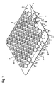
- einen Transportbehälter zusammen mit in dem Transportbehälter in einer Aufnahmeeinrichtung angeordneten pharmazeutischen Behältern in perspektivischer Ansicht,
- Fig. 2
- die Aufnahmeeinrichtung mit den pharmazeutischen Behältern gemäß der
Fig. 1 , ebenfalls in perspektivischer Ansicht, - Fig. 3
- eine erfindungsgemäße Vorrichtung zur Entnahme von Behältern in Draufsicht und
- Fig. 4
- die Vorrichtung gemäß
Fig. 3 in einer perspektivischen Darstellung.
- Fig. 1
- a transport container together with in the transport container in a receiving device arranged pharmaceutical containers in perspective view,
- Fig. 2
- the receiving device with the pharmaceutical containers according to the
Fig. 1 , also in perspective view, - Fig. 3
- a device according to the invention for the removal of containers in plan view and
- Fig. 4
- the device according to
Fig. 3 in a perspective view.
In der
In der
In den
Um Spritzenkörper 3 auszusondern, welche im Laufe der Produktionsschritte innerhalb der Verpackungsanlage 100 beispielsweise entweder mit einer nicht richtigen Menge an Füllgut befüllt wurden, oder deren Verschlussstopfen oder ähnliches beispielsweise nicht korrekt auf die Spritzenkörper 3 aufgebracht wurde, schließt sich die Vorrichtung 10 insbesondere an das Ende der eigentlichen Verpackungsanlage 100 an. Die Vorrichtung 10 kann aber ausdrücklich auch dazu dienen, Spritzenkörper 3 lediglich zu Kontrollzwecken zu entnehmen, auch wenn diese vorher nicht als potentiell fehlerhaft eingruppiert wurden. Im Folgenden wird jedoch der Einfachheit halber von potentiell fehlerhaften Spritzenkörpern 3 gesprochen.In order to weed out syringe bodies 3, which were filled in the course of the production steps within the
Die Verpackungsanlage 100 weist eine Steuereinrichtung 110 auf, welche alle während des Produktionsprozesses an den einzelnen Spritzenkörpern 3 aufgetretenen potenziellen Fehler erfasst und abspeichert. Die Steuereinrichtung 110 der Verpackungsanlage 100 ist hierbei mit einer Steuereinrichtung 11 der Vorrichtung 10 verbunden. Insbesondere werden mittels der Steuereinrichtung 110 der Verpackungsanlage 100 Daten über potenziell fehlerhafte Spritzenkörper 3 an die Steuereinrichtung 11 der Vorrichtung 10 übermittelt.The
Die Vorrichtung 10 weist ein Gestell bzw. eine Tischplatte 12 auf. Entlang einer Längsseite der Tischplatte 12 erstreckt sich eine erste Förder- bzw. Transporteinrichtung 15, welche beispielhaft zwei parallel zueinander beabstandete Fördergurte 16 und 17 aufweist, auf denen die Transportbehälter 1 durch Reibschluss insbesondere kontinuierlich gefördert werden. Hierbei ist mit dem Pfeil 18 (
Die erste Transporteinrichtung 15 wirkt über eine erste Überschiebeeinheit 22 mit einer zweiten Transporteinrichtung 23 zusammen. Die zweite Transporteinrichtung 23 umfasst ein Ausschleusband 24, welches quer zur ersten Transporteinrichtung 15 am Ende der Tischplatte 12 nahe des Austrittsbereichs 20 angeordnet ist. Parallel zur ersten Transporteinrichtung 15 ist ein weiteres Transportband 26 angeordnet, welches ebenfalls Bestandteil der zweiten Transporteinrichtung 23 ist. Das Transportband 26 erstreckt sich nahezu über die gesamte Länge der Vorrichtung 10 und weist an seinem Ende eine wiederum rechtwinklig zum Transportband 26 angeordnete Überschubeinheit 27 auf.The
Wesentlich ist noch, dass fluchtend mit dem Transportband 26 im Bereich des Ausschleusbandes 24 eine zweite Überschiebeeinheit 28 angeordnet ist.It is also essential that in alignment with the
Im Bereich der ersten Transporteinrichtung 15 und der zweiten Transporteinrichtung 23 sind mehrere auf- und abbewegbare Sperrelemente 29 angeordnet, welche dazu dienen, die Bewegung eines Transportbehälters 1 auf den Transporteinrichtungen 15 und 23 zu stoppen. Die soweit bezeichneten und beschriebenen Transporteinrichtungen 15 und 23 sind aus der Fördertechnik bereits allgemein bekannt, so dass auf deren genaue Funktionsweise an dieser Stelle nicht näher eingegangen wird. Zwischen der ersten Transporteinrichtung 15 und dem Transportband 26 sind beispielhaft drei Kameras 31 bis 33 auf der Tischplatte 12 angeordnet. Hierbei dient jede der Kameras 31 bis 33 dazu, einen beispielsweise an einer Seitenwand des Transportbehälters 1 angeordneten Code oder ein dort angeordnetes Schild zu erfassen (nicht dargestellt) und mit innerhalb der Steuereinrichtung 11 der Vorrichtung 10 abgelegten Informationen zu vergleichen.In the area of the
Hierbei ist die erste Kamera 32 zur Identifikation von auf der ersten Transporteinrichtung 15 transportierten Transportbehältern 1 vorgesehen, während die zweite Kamera 33 zur Kontrolle des Aufdruckes durch einen Druckkopf 34 auf den Transportbehälter 1 dient. Durch die Kamera 31 erfolgt eine Identifikation von auf dem Transportband 26 befindlichen Transportbehältern 1. Zwischen den beiden Kameras 32 und 33 ist im Bereich des Transportbandes 15 weiterhin der Druckkopf 34 angeordnet, mittels dessen Hilfe Informationen, welche mittels der Kameras 31 bis 33 erfasst werden, entweder zu aktualisieren, oder aber neue Informationen z.B. durch ein Druckbild aufzubringen.Here, the
In etwa im mittleren Bereich der Tischplatte 12 ist ein Handhabungsroboter 35 angeordnet, welcher an einem Ende eines Arms 36 ein in einer vertikalen Achse 37 schwenkbares Kombiwerkzeug 38 aufweist. Das Kombiwerkzeug 38 weist hierbei eine Block- bzw. längliche Form auf, wobei an der einen Seite des Kombiwerkzeugs 38 eine Vielzahl von Greifeinheiten 39 angeordnet ist, während auf der den Greifeinheiten 39 gegenüberliegenden Seite des Kombiwerkzeugs 38 an einem Endbereich ein einzelnes Greifwerkzeug 41 angeordnet ist. Während sich mit den Greifeinheiten 39 eine komplette Reihe von Spritzenkörpern 3 aus der Aufnahmeeinrichtung 2 oder eine Teilmenge davon entnehmen lässt, dient das Greifwerkzeug 41 dazu, einen einzelnen Spritzenkörper 3 aus der Aufnahmeeinrichtung 2 zu entnehmen.In approximately in the central region of the
An den Handhabungsroboter 35 schließt sich in der mit dem Pfeil 42 in der
Ferner erkennt man auf der Tischplatte 12 noch einen Auswurfbehälter 47 für als fehlerhaft erkannte Spritzenkörper 3 sowie eine Einheit 48, mittels der komplette Reihen von Spritzenkörpern 3 zum manuellen Nachwiegen eines Spritzenkörpers 3 oder einer Behälterreihe entnommen werden können. Nicht dargestellt, aber optional vorgesehen, können im Bereich des Handhabungsroboters 35 noch Prüfeinrichtungen, insbesondere Wiegeeinrichtungen, angeordnet sein, um einzelne oder mehrere Spritzenkörper 3 hinsichtlich der korrekten Füllmenge zu überprüfen.Further, one recognizes on the
Die soweit beschriebene Vorrichtung 10 arbeitet wie folgt: Von der Steuereinrichtung 110 der Verpackungsanlage 100 werden der Steuereinrichtung 11 der Vorrichtung 10 die Daten hinsichtlich potenziell fehlerhafter Spritzenkörper 3 übermittelt. Insbesondere werden hierbei die Daten bzw. ein Bild des an dem Transportbehälter 1 aufgedruckten Identifikationsmerkmals übermittelt, aus dem hervorgeht, welcher Transportbehälter 1 und welche in dem Transportbehälter 1 angeordneten Spritzenkörper 3 potenziell fehlerhaft sind. Die in gleichmäßigen oder ungleichmäßigen Abständen auf der ersten Transporteinrichtung 15 geförderten Transportbehälter 1 gelangen.zunächst in den Aufnahmebereich der ersten Kamera 32, wo dieser mittels der Sperrelemente 29 an der weiteren Förderung gehindert wird. Mit der Kamera 32 wird die Identifikation des Transportbehälters 1 vorgenommen und mit dem in der Steuereinrichtung 11 abgelegten Bild bzw. mit den dort abgelegten Informationen verglichen. Sollte es sich dabei herausstellen, dass der betreffende Transportbehälter 1 keine potenziell fehlerhaften Spritzenkörper 3 enthält, so gelangt der Transportbehälter 1 im weiteren Verlauf unmittelbar an den Druckkopf 34, um mittels diesem optional Informationen auf den Transportbehälter 1 aufzubringen. Wird der Aufdruck im Anschluss durch die Kamera 33 als lesbar bestätigt, erfolgt kein Überschub durch die erste Überschiebeeinheit 22 auf das Ausschleusband 24. Vielmehr lassen die Sperrelemente 29 den Transportbehälter 1 beispielsweise auf ein Rollenband 49 passieren.The
Sollte es sich demgegenüber bei dem Transportbehälter 1 um einen Transportbehälter 1 handeln, welcher potenziell fehlerhafte Spritzenkörper 3 enthält, oder bei dem eine Prüfung der Spritzenkörper 3 erfolgen soll, oder der nicht identifiziert werden konnte oder der Identifikationsaufdruck nicht korrekt ist, so wird der betreffende Transportbehälter 1 von der ersten Transporteinrichtung 15 auf das Ausschleusband 24 übergeschoben. Wurde der Transportbehälter 1 identifiziert (und sind potentiell fehlerhafte Spritzenkörper 3 daraus zu entnehmen oder eine Prüfung durchzuführen), so wird der Transportbehälter 1 von der zweiten Überschiebeeinheit 28 am Ausschleusband 24 auf das Transportband 26 übergeschoben. Ansonsten lassen die Sperrelemente 29 den Transportbehälter 1 durchlaufen, so dass dieser komplett ausgeschleust wird. Auf dem Transportband 26 gelangt der Transportbehälter 1 zur erneuten Identifikation mittels der Kamera 31. Dort wird der entsprechende Transportbehälter 1 nochmals identifiziert, um sicherzustellen, dass es sich bei dem Transportbehälter 1 um denjenigen Transportbehälter 1 handelt, welcher bereits mit der Kamera 32 als potenziell fehlerhafte Spritzenkörper 3 enthaltender Transportbehälter 1 identifiziert wurde. Mittels der Aushebeeinrichtung 45 gelangt die Aufnahmeeinrichtung 2 auf den Transportrahmen 46. Der Transportrahmen 46 fördert die entnommene Aufnahmeeinrichtung 2 in den Bereich der Anhebeeinheit 43, wo die entsprechende Reihe von Spritzenkörpern 3 aus der Aufnahmeeinrichtung 2 angehoben wird, um anschließend mittels des Handhabungsroboters 35 bzw. des Kombiwerkzeugs 38 den bzw. die potenziell fehlerhaften Spritzenkörper 3 zu entnehmen. Es besteht nun die Möglichkeit, dass der bzw. die potenziell fehlerhaften Spritzenkörper 3 auf einer nicht dargestellten Prüfeinrichtung überprüft werden, und beim Feststellen eines Fehlers der oder die betreffenden Spritzenkörper 3 in den Ausscheidebehälter 47 überführt werden. Sollte dies geschehen, so ist es auch denkbar bzw. möglich, innerhalb der Vorrichtung 10 bevorratete "Gut"-Spritzenkörper 3 in die entsprechende Aufnahmen 5 der Aufnahmeeinrichtung 2 zu überführen, so dass die Aufnahmeeinrichtung 2 vollständig mit potenziell fehlerfreien Spritzenkörpern 3 befüllt ist.If, on the other hand, the transport container 1 is a transport container 1 which contains potentially defective syringe bodies 3, or if the syringe body 3 is to be checked, or if it could not be identified or the identification imprint is incorrect, the relevant transport container will become 1 pushed by the
Die so behandelte Aufnahmeeinrichtung 2 kann anschließend wieder mittels des Transportrahmens 46 und der Aushebeeinrichtung 45 in den Transportbehälter 1 eingesetzt werden, worauf anschließend der betreffende Transportbehälter 1 mittels der Überschiebeeinheit 27 wieder in den Produktionsfluss bzw. in eine Lücke auf der ersten Transporteinrichtung 15 übergeschoben wird.The receiving device 2 thus treated can then be inserted into the transport container 1 again by means of the
Wesentlich ist noch, dass diejenigen Transportbehälter 1, welche auch nach mehrmaligem Umlauf in der Vorrichtung 10 nicht identifiziert worden sind, bei denen eine Prüfung fehlgeschlagen ist oder der Aufdruck des Druckkopfes 34 nicht lesbar ist nur an einem Ort ausgeschleust werden, nämlich über das Ausschleusband 24.It is also essential that those transport containers 1, which have not been identified even after repeated circulation in the
Die soweit beschriebene Vorrichtung 10 kann in vielfältiger Art und Weise modifiziert bzw. abgewandelt werden. So ist die Vorrichtung 10 nicht auf die Verwendung der beschriebenen Transporteinrichtungen 15 und 23 beschränkt, sondern kann auch andersartig ausgebildete Transporteinrichtungen aufweisen. Wesentlich ist lediglich, dass neben dem Hauptförderweg für die Transportbehälter 1 eine Umleitung in Art eines "Bypass" geschaffen wird, welcher der Kontrolle und Ausschleusung von potenziell fehlerhaften oder zu überprüfenden Spritzenkörpern 3 dient, wobei anstelle von Spritzenkörpern 3 selbstverständlich auch andere Behälter verarbeitet werden können. Durch eine modifizierte Anordnung der Kameras 31 bis 33 bzw. anderer geeigneter Identifizierungseinrichtungen ist es möglich, die Transportbehälter 1 unabhängig von dem Ort eines Identifikationsmerkmals zu erkennen. Ebenso ist es denkbar, den Druckkopf 34 derart anzuordnen, dass ein Stausdruck auf jeder Seite des Transportbehälters 1 möglich ist.The
Claims (9)
- Apparatus (10) for removing containers (3), in particular pharmaceutical containers (3), from a first transporting device (15), which conveys the containers (3) in transporting containers (1), having a first identification device (32), which is arranged on the transporting path of the first transporting device (15) and is intended for identifying the transporting containers (1), characterized in that the apparatus comprises a discharging device (24), which is arranged downstream of the first identification device (32) and transfers a transporting container (1) onto a second transporting device (23), on the conveying route of which is arranged a removal device (35) for removing at least one container (3), and also comprises an introduction device (27), for reintroducing the transporting container (1) into the first conveying device (15).
- Apparatus according to Claim 1,
characterized
by the arrangement, in the region of the second transporting device (23), of a device (45, 46) which is intended for removing from the transporting container (1), and for transporting, an accommodating device (2), for accommodating a multiplicity of containers (3) arranged in holders (4), and which feeds the accommodating device (2) to the removal device (43) in order for at least one container (3) to be removed from the transporting container (1). - Apparatus according to either of Claims 1 and 2,
characterized
in that a second identification device (31) is arranged in the region of the second transporting device (23), and in that the second identification device (31) interacts with the removal device (35) for the removal of at least one container (3). - Apparatus according to at least one of Claims 1 to 3,
characterized
in that a device (28) for discharging transporting containers (1) is arranged in the region of the second transporting device (23). - Apparatus according to one of Claims 1 to 4,
characterized
in that a testing device, in particular a weighing device, is arranged in the region of the second transporting device (23). - Apparatus according to one of Claims 1 to 5,
characterized
in that the first and the second transporting device (15, 23) are each designed as transporting belts. - Apparatus according to one of Claims 1 to 6,
characterized
in that the apparatus (10) has merely a single discharging device (49). - Apparatus according to either of Claims 1 and 7,
characterized by
the arrangement, in the region of the first transporting device (15), of device (34) for marking the transporting containers (1) transported in the region of the first transporting device (15). - Packaging installation (100) having an apparatus (10) according to one of Claims 1 to 8,
characterized
in that the first identification device (31) of the apparatus (10) is coupled at least indirectly to a control device (110) of the packaging installation (100).
Applications Claiming Priority (2)
| Application Number | Priority Date | Filing Date | Title |
|---|---|---|---|
| DE102009046662A DE102009046662A1 (en) | 2009-11-12 | 2009-11-12 | Device for removing containers |
| PCT/EP2010/064627 WO2011057862A1 (en) | 2009-11-12 | 2010-10-01 | Device for extracting containers |
Publications (2)
| Publication Number | Publication Date |
|---|---|
| EP2499501A1 EP2499501A1 (en) | 2012-09-19 |
| EP2499501B1 true EP2499501B1 (en) | 2013-07-03 |
Family
ID=43416615
Family Applications (1)
| Application Number | Title | Priority Date | Filing Date |
|---|---|---|---|
| EP10762647.5A Active EP2499501B1 (en) | 2009-11-12 | 2010-10-01 | Device for extracting containers and packaging machine |
Country Status (6)
| Country | Link |
|---|---|
| US (1) | US20130015108A1 (en) |
| EP (1) | EP2499501B1 (en) |
| CN (1) | CN102612654B (en) |
| DE (1) | DE102009046662A1 (en) |
| IN (1) | IN2012DN02146A (en) |
| WO (1) | WO2011057862A1 (en) |
Cited By (2)
| Publication number | Priority date | Publication date | Assignee | Title |
|---|---|---|---|---|
| CH712191A1 (en) * | 2016-03-04 | 2017-09-15 | Wrh Walter Reist Holding Ag | Conveyor with a conveyor chain and with a plurality of attached to the conveyor chain Fördergutbehältern. |
| DE102019129329A1 (en) * | 2019-10-30 | 2021-05-06 | Ma Micro Automation Gmbh | Handling device and removal station |
Families Citing this family (4)
| Publication number | Priority date | Publication date | Assignee | Title |
|---|---|---|---|---|
| DE102016209710A1 (en) * | 2016-06-02 | 2017-12-07 | Robert Bosch Gmbh | Apparatus and method for inspecting containers |
| WO2019094547A1 (en) * | 2017-11-08 | 2019-05-16 | Windgap Medical, Inc. | A system and method for providing and assembling an auto-injector |
| CN109436801A (en) * | 2018-11-29 | 2019-03-08 | 杭州捷能科技有限公司 | A kind of part automatic charging device and part automatic charging method |
| DE102019201950A1 (en) | 2019-02-14 | 2020-08-20 | Syntegon Technology Gmbh | Device and method for inserting mixing balls in pharmaceutical containers |
Family Cites Families (21)
| Publication number | Priority date | Publication date | Assignee | Title |
|---|---|---|---|---|
| DE3408081A1 (en) * | 1984-03-05 | 1985-09-19 | Siemens AG, 1000 Berlin und 8000 München | PICKING DEVICE |
| US5578331A (en) * | 1994-06-10 | 1996-11-26 | Vision Products, Inc. | Automated apparatus for preparing contact lenses for inspection and packaging |
| US5623415A (en) * | 1995-02-16 | 1997-04-22 | Smithkline Beecham Corporation | Automated sampling and testing of biological materials |
| DE19604100C2 (en) * | 1996-02-06 | 1997-12-18 | Bosch Gmbh Robert | Device for handling fillable tubular objects arranged in an upwardly open container |
| JP3031242B2 (en) * | 1996-05-20 | 2000-04-10 | 株式会社日立製作所 | Multi-item analyzer |
| WO1998001760A2 (en) * | 1996-07-05 | 1998-01-15 | Beckman Coulter, Inc. | Automated sample processing system |
| JP3336894B2 (en) * | 1997-01-29 | 2002-10-21 | 株式会社日立製作所 | Automatic analyzer |
| DE19819812C2 (en) * | 1998-05-04 | 2000-11-02 | Olympus Diagnostica Gmbh | Laboratory primary sample distributor with a distribution device |
| DE19819813C2 (en) * | 1998-05-04 | 2000-11-02 | Olympus Diagnostica Gmbh | Use of a laboratory primary sample distributor for archiving |
| JP4136187B2 (en) * | 1999-05-14 | 2008-08-20 | シスメックス株式会社 | Sample transfer device |
| DE10204247B4 (en) * | 2002-02-02 | 2007-06-14 | Adam Opel Ag | Method for removing and introducing a component from and into a transport system and device therefor |
| FR2867861B1 (en) * | 2004-03-16 | 2006-07-14 | Abx Sa | DEVICE FOR SUPPLYING TOTAL BLOOD ANALYZERS |
| DE102004035061A1 (en) * | 2004-07-20 | 2006-02-16 | Bausch + Ströbel Maschinenfabrik Ilshofen GmbH + Co. KG | Device for filling an injection body with a liquid comprises a weighing unit having a lifting mechanism for lifting the injection body from its seat in the carrier plate |
| EP1630550A1 (en) * | 2004-08-27 | 2006-03-01 | Moller & Devicon A/S | Methods and apparatuses of detecting foreign particles or faults in a plurality of filled containers |
| DE202004018512U1 (en) * | 2004-10-08 | 2005-09-22 | Kuka Schweissanlagen Gmbh | Process line especially for vehicle body sections has a closed loop transporter with switches to feed separate groups of process stations |
| CH702317B1 (en) * | 2007-08-02 | 2011-06-15 | Stevanato Group Internat As | Structure of the pack of glass vials for pharmaceutical use. |
| DE102007048684B4 (en) * | 2007-10-10 | 2010-09-09 | Polysius Ag | laboratory system |
| JP5198094B2 (en) * | 2008-03-07 | 2013-05-15 | シスメックス株式会社 | Analysis equipment |
| US8822224B2 (en) * | 2008-07-02 | 2014-09-02 | Prairie Ventures Llc | Method for automatic testing of anatomical laboratory specimens |
| EP2148205B1 (en) * | 2008-07-25 | 2013-01-02 | F. Hoffmann-La Roche AG | A method and laboratory system for handling sample tubes and an image analysing unit |
| JP5378859B2 (en) * | 2009-03-30 | 2013-12-25 | シスメックス株式会社 | Sample testing system |
-
2009
- 2009-11-12 DE DE102009046662A patent/DE102009046662A1/en not_active Withdrawn
-
2010
- 2010-10-01 CN CN201080051075.2A patent/CN102612654B/en active Active
- 2010-10-01 IN IN2146DEN2012 patent/IN2012DN02146A/en unknown
- 2010-10-01 EP EP10762647.5A patent/EP2499501B1/en active Active
- 2010-10-01 US US13/509,680 patent/US20130015108A1/en not_active Abandoned
- 2010-10-01 WO PCT/EP2010/064627 patent/WO2011057862A1/en active Application Filing
Cited By (3)
| Publication number | Priority date | Publication date | Assignee | Title |
|---|---|---|---|---|
| CH712191A1 (en) * | 2016-03-04 | 2017-09-15 | Wrh Walter Reist Holding Ag | Conveyor with a conveyor chain and with a plurality of attached to the conveyor chain Fördergutbehältern. |
| US10011430B2 (en) | 2016-03-04 | 2018-07-03 | Wrh Walter Reist Holding Ag | Conveying device with a conveying chain |
| DE102019129329A1 (en) * | 2019-10-30 | 2021-05-06 | Ma Micro Automation Gmbh | Handling device and removal station |
Also Published As
| Publication number | Publication date |
|---|---|
| DE102009046662A1 (en) | 2011-05-19 |
| CN102612654B (en) | 2016-07-06 |
| IN2012DN02146A (en) | 2015-08-07 |
| WO2011057862A1 (en) | 2011-05-19 |
| US20130015108A1 (en) | 2013-01-17 |
| EP2499501A1 (en) | 2012-09-19 |
| CN102612654A (en) | 2012-07-25 |
Similar Documents
| Publication | Publication Date | Title |
|---|---|---|
| EP2499501B1 (en) | Device for extracting containers and packaging machine | |
| EP2280873B1 (en) | Filling and sealing machine for containers | |
| EP2448820B1 (en) | Device for filling and sealing pharmaceutical containers | |
| EP2570350B1 (en) | Method and device for filling and sealing pharmaceutical objects | |
| EP2799374B1 (en) | System and method for removing beverage containers from a moving transport device | |
| EP2698213B1 (en) | Marking device for marking containers, container treatment device and a method for marking containers | |
| DE102004023473B4 (en) | Packaging machine and method for feeding containers in a packaging machine | |
| EP2345587A1 (en) | Packaging assembly with discharge station | |
| EP2560602B1 (en) | Device for filling and closing capsules filled with at least one filler | |
| DE3324449C2 (en) | ||
| DE102017100010A1 (en) | Device and method for filling nested containers | |
| EP2006204B1 (en) | Facility for filling pharmaceutical products into bottle-like containers | |
| DE102014001741A1 (en) | Labeling device, labeling system and method for loading a product with a label | |
| WO2019048368A1 (en) | Device and method for orienting packages | |
| DE102015203060A1 (en) | Inspection device for inspecting containers | |
| EP1655227B1 (en) | Machine for unloading of containers from transporting outercase | |
| EP3380420B1 (en) | Device and method for separating and/or testing containers | |
| EP3678792B1 (en) | Device and method for removing containers which have been incorrectly imprinted in a direct printing machine | |
| EP3789129A1 (en) | Method and apparatus for monitoring the operation of a container cleaner | |
| EP3463695B1 (en) | Device and method for inspecting containers | |
| DE102018128498A1 (en) | Component tracking procedures | |
| DE102021127564B3 (en) | Device and method for closing containers with closures | |
| EP3733342B1 (en) | Transport installation | |
| DE102017108903B4 (en) | Treatment device and container treatment machine | |
| DE102017129560B4 (en) | Device and system for blistering medicines and method for operating the same |
Legal Events
| Date | Code | Title | Description |
|---|---|---|---|
| PUAI | Public reference made under article 153(3) epc to a published international application that has entered the european phase |
Free format text: ORIGINAL CODE: 0009012 |
|
| 17P | Request for examination filed |
Effective date: 20120612 |
|
| AK | Designated contracting states |
Kind code of ref document: A1 Designated state(s): AL AT BE BG CH CY CZ DE DK EE ES FI FR GB GR HR HU IE IS IT LI LT LU LV MC MK MT NL NO PL PT RO RS SE SI SK SM TR |
|
| DAX | Request for extension of the european patent (deleted) | ||
| GRAP | Despatch of communication of intention to grant a patent |
Free format text: ORIGINAL CODE: EPIDOSNIGR1 |
|
| INTG | Intention to grant announced |
Effective date: 20130408 |
|
| GRAS | Grant fee paid |
Free format text: ORIGINAL CODE: EPIDOSNIGR3 |
|
| GRAA | (expected) grant |
Free format text: ORIGINAL CODE: 0009210 |
|
| AK | Designated contracting states |
Kind code of ref document: B1 Designated state(s): AL AT BE BG CH CY CZ DE DK EE ES FI FR GB GR HR HU IE IS IT LI LT LU LV MC MK MT NL NO PL PT RO RS SE SI SK SM TR |
|
| REG | Reference to a national code |
Ref country code: GB Ref legal event code: FG4D Free format text: NOT ENGLISH |
|
| REG | Reference to a national code |
Ref country code: AT Ref legal event code: REF Ref document number: 620061 Country of ref document: AT Kind code of ref document: T Effective date: 20130715 Ref country code: CH Ref legal event code: EP |
|
| REG | Reference to a national code |
Ref country code: IE Ref legal event code: FG4D Free format text: LANGUAGE OF EP DOCUMENT: GERMAN |
|
| REG | Reference to a national code |
Ref country code: DE Ref legal event code: R096 Ref document number: 502010003913 Country of ref document: DE Effective date: 20130829 |
|
| PG25 | Lapsed in a contracting state [announced via postgrant information from national office to epo] |
Ref country code: SI Free format text: LAPSE BECAUSE OF FAILURE TO SUBMIT A TRANSLATION OF THE DESCRIPTION OR TO PAY THE FEE WITHIN THE PRESCRIBED TIME-LIMIT Effective date: 20130703 |
|
| REG | Reference to a national code |
Ref country code: NL Ref legal event code: VDEP Effective date: 20130703 |
|
| REG | Reference to a national code |
Ref country code: LT Ref legal event code: MG4D |
|
| PG25 | Lapsed in a contracting state [announced via postgrant information from national office to epo] |
Ref country code: CY Free format text: LAPSE BECAUSE OF FAILURE TO SUBMIT A TRANSLATION OF THE DESCRIPTION OR TO PAY THE FEE WITHIN THE PRESCRIBED TIME-LIMIT Effective date: 20130911 Ref country code: NO Free format text: LAPSE BECAUSE OF FAILURE TO SUBMIT A TRANSLATION OF THE DESCRIPTION OR TO PAY THE FEE WITHIN THE PRESCRIBED TIME-LIMIT Effective date: 20131003 Ref country code: LT Free format text: LAPSE BECAUSE OF FAILURE TO SUBMIT A TRANSLATION OF THE DESCRIPTION OR TO PAY THE FEE WITHIN THE PRESCRIBED TIME-LIMIT Effective date: 20130703 Ref country code: IS Free format text: LAPSE BECAUSE OF FAILURE TO SUBMIT A TRANSLATION OF THE DESCRIPTION OR TO PAY THE FEE WITHIN THE PRESCRIBED TIME-LIMIT Effective date: 20131103 Ref country code: SE Free format text: LAPSE BECAUSE OF FAILURE TO SUBMIT A TRANSLATION OF THE DESCRIPTION OR TO PAY THE FEE WITHIN THE PRESCRIBED TIME-LIMIT Effective date: 20130703 Ref country code: HR Free format text: LAPSE BECAUSE OF FAILURE TO SUBMIT A TRANSLATION OF THE DESCRIPTION OR TO PAY THE FEE WITHIN THE PRESCRIBED TIME-LIMIT Effective date: 20130703 Ref country code: PT Free format text: LAPSE BECAUSE OF FAILURE TO SUBMIT A TRANSLATION OF THE DESCRIPTION OR TO PAY THE FEE WITHIN THE PRESCRIBED TIME-LIMIT Effective date: 20131104 |
|
| PG25 | Lapsed in a contracting state [announced via postgrant information from national office to epo] |
Ref country code: NL Free format text: LAPSE BECAUSE OF FAILURE TO SUBMIT A TRANSLATION OF THE DESCRIPTION OR TO PAY THE FEE WITHIN THE PRESCRIBED TIME-LIMIT Effective date: 20130703 Ref country code: FI Free format text: LAPSE BECAUSE OF FAILURE TO SUBMIT A TRANSLATION OF THE DESCRIPTION OR TO PAY THE FEE WITHIN THE PRESCRIBED TIME-LIMIT Effective date: 20130703 Ref country code: GR Free format text: LAPSE BECAUSE OF FAILURE TO SUBMIT A TRANSLATION OF THE DESCRIPTION OR TO PAY THE FEE WITHIN THE PRESCRIBED TIME-LIMIT Effective date: 20131004 Ref country code: PL Free format text: LAPSE BECAUSE OF FAILURE TO SUBMIT A TRANSLATION OF THE DESCRIPTION OR TO PAY THE FEE WITHIN THE PRESCRIBED TIME-LIMIT Effective date: 20130703 Ref country code: ES Free format text: LAPSE BECAUSE OF FAILURE TO SUBMIT A TRANSLATION OF THE DESCRIPTION OR TO PAY THE FEE WITHIN THE PRESCRIBED TIME-LIMIT Effective date: 20131014 Ref country code: LV Free format text: LAPSE BECAUSE OF FAILURE TO SUBMIT A TRANSLATION OF THE DESCRIPTION OR TO PAY THE FEE WITHIN THE PRESCRIBED TIME-LIMIT Effective date: 20130703 |
|
| PG25 | Lapsed in a contracting state [announced via postgrant information from national office to epo] |
Ref country code: CY Free format text: LAPSE BECAUSE OF FAILURE TO SUBMIT A TRANSLATION OF THE DESCRIPTION OR TO PAY THE FEE WITHIN THE PRESCRIBED TIME-LIMIT Effective date: 20130703 |
|
| BERE | Be: lapsed |
Owner name: ROBERT BOSCH G.M.B.H. Effective date: 20131031 |
|
| PG25 | Lapsed in a contracting state [announced via postgrant information from national office to epo] |
Ref country code: CZ Free format text: LAPSE BECAUSE OF FAILURE TO SUBMIT A TRANSLATION OF THE DESCRIPTION OR TO PAY THE FEE WITHIN THE PRESCRIBED TIME-LIMIT Effective date: 20130703 Ref country code: DK Free format text: LAPSE BECAUSE OF FAILURE TO SUBMIT A TRANSLATION OF THE DESCRIPTION OR TO PAY THE FEE WITHIN THE PRESCRIBED TIME-LIMIT Effective date: 20130703 Ref country code: SK Free format text: LAPSE BECAUSE OF FAILURE TO SUBMIT A TRANSLATION OF THE DESCRIPTION OR TO PAY THE FEE WITHIN THE PRESCRIBED TIME-LIMIT Effective date: 20130703 Ref country code: RO Free format text: LAPSE BECAUSE OF FAILURE TO SUBMIT A TRANSLATION OF THE DESCRIPTION OR TO PAY THE FEE WITHIN THE PRESCRIBED TIME-LIMIT Effective date: 20130703 Ref country code: EE Free format text: LAPSE BECAUSE OF FAILURE TO SUBMIT A TRANSLATION OF THE DESCRIPTION OR TO PAY THE FEE WITHIN THE PRESCRIBED TIME-LIMIT Effective date: 20130703 |
|
| PLBE | No opposition filed within time limit |
Free format text: ORIGINAL CODE: 0009261 |
|
| STAA | Information on the status of an ep patent application or granted ep patent |
Free format text: STATUS: NO OPPOSITION FILED WITHIN TIME LIMIT |
|
| PG25 | Lapsed in a contracting state [announced via postgrant information from national office to epo] |
Ref country code: MC Free format text: LAPSE BECAUSE OF FAILURE TO SUBMIT A TRANSLATION OF THE DESCRIPTION OR TO PAY THE FEE WITHIN THE PRESCRIBED TIME-LIMIT Effective date: 20130703 |
|
| 26N | No opposition filed |
Effective date: 20140404 |
|
| REG | Reference to a national code |
Ref country code: DE Ref legal event code: R097 Ref document number: 502010003913 Country of ref document: DE Effective date: 20140404 |
|
| REG | Reference to a national code |
Ref country code: IE Ref legal event code: MM4A |
|
| REG | Reference to a national code |
Ref country code: FR Ref legal event code: ST Effective date: 20140630 |
|
| PG25 | Lapsed in a contracting state [announced via postgrant information from national office to epo] |
Ref country code: FR Free format text: LAPSE BECAUSE OF NON-PAYMENT OF DUE FEES Effective date: 20131031 |
|
| PG25 | Lapsed in a contracting state [announced via postgrant information from national office to epo] |
Ref country code: BE Free format text: LAPSE BECAUSE OF NON-PAYMENT OF DUE FEES Effective date: 20131031 |
|
| PG25 | Lapsed in a contracting state [announced via postgrant information from national office to epo] |
Ref country code: IE Free format text: LAPSE BECAUSE OF NON-PAYMENT OF DUE FEES Effective date: 20131001 |
|
| PG25 | Lapsed in a contracting state [announced via postgrant information from national office to epo] |
Ref country code: SM Free format text: LAPSE BECAUSE OF FAILURE TO SUBMIT A TRANSLATION OF THE DESCRIPTION OR TO PAY THE FEE WITHIN THE PRESCRIBED TIME-LIMIT Effective date: 20130703 |
|
| REG | Reference to a national code |
Ref country code: CH Ref legal event code: PL |
|
| GBPC | Gb: european patent ceased through non-payment of renewal fee |
Effective date: 20141001 |
|
| PG25 | Lapsed in a contracting state [announced via postgrant information from national office to epo] |
Ref country code: HU Free format text: LAPSE BECAUSE OF FAILURE TO SUBMIT A TRANSLATION OF THE DESCRIPTION OR TO PAY THE FEE WITHIN THE PRESCRIBED TIME-LIMIT; INVALID AB INITIO Effective date: 20101001 Ref country code: CH Free format text: LAPSE BECAUSE OF NON-PAYMENT OF DUE FEES Effective date: 20141031 Ref country code: RS Free format text: LAPSE BECAUSE OF FAILURE TO SUBMIT A TRANSLATION OF THE DESCRIPTION OR TO PAY THE FEE WITHIN THE PRESCRIBED TIME-LIMIT Effective date: 20131003 Ref country code: LU Free format text: LAPSE BECAUSE OF NON-PAYMENT OF DUE FEES Effective date: 20131001 Ref country code: BG Free format text: LAPSE BECAUSE OF FAILURE TO SUBMIT A TRANSLATION OF THE DESCRIPTION OR TO PAY THE FEE WITHIN THE PRESCRIBED TIME-LIMIT Effective date: 20130703 Ref country code: GB Free format text: LAPSE BECAUSE OF NON-PAYMENT OF DUE FEES Effective date: 20141001 Ref country code: LI Free format text: LAPSE BECAUSE OF NON-PAYMENT OF DUE FEES Effective date: 20141031 Ref country code: MK Free format text: LAPSE BECAUSE OF FAILURE TO SUBMIT A TRANSLATION OF THE DESCRIPTION OR TO PAY THE FEE WITHIN THE PRESCRIBED TIME-LIMIT Effective date: 20130703 |
|
| PG25 | Lapsed in a contracting state [announced via postgrant information from national office to epo] |
Ref country code: MT Free format text: LAPSE BECAUSE OF FAILURE TO SUBMIT A TRANSLATION OF THE DESCRIPTION OR TO PAY THE FEE WITHIN THE PRESCRIBED TIME-LIMIT Effective date: 20130703 |
|
| PG25 | Lapsed in a contracting state [announced via postgrant information from national office to epo] |
Ref country code: TR Free format text: LAPSE BECAUSE OF FAILURE TO SUBMIT A TRANSLATION OF THE DESCRIPTION OR TO PAY THE FEE WITHIN THE PRESCRIBED TIME-LIMIT Effective date: 20130703 |
|
| REG | Reference to a national code |
Ref country code: AT Ref legal event code: MM01 Ref document number: 620061 Country of ref document: AT Kind code of ref document: T Effective date: 20151001 |
|
| PG25 | Lapsed in a contracting state [announced via postgrant information from national office to epo] |
Ref country code: AT Free format text: LAPSE BECAUSE OF NON-PAYMENT OF DUE FEES Effective date: 20151001 |
|
| PG25 | Lapsed in a contracting state [announced via postgrant information from national office to epo] |
Ref country code: AL Free format text: LAPSE BECAUSE OF FAILURE TO SUBMIT A TRANSLATION OF THE DESCRIPTION OR TO PAY THE FEE WITHIN THE PRESCRIBED TIME-LIMIT Effective date: 20130703 |
|
| REG | Reference to a national code |
Ref country code: DE Ref legal event code: R082 Ref document number: 502010003913 Country of ref document: DE Representative=s name: DREISS PATENTANWAELTE PARTG MBB, DE Ref country code: DE Ref legal event code: R081 Ref document number: 502010003913 Country of ref document: DE Owner name: SYNTEGON TECHNOLOGY GMBH, DE Free format text: FORMER OWNER: ROBERT BOSCH GMBH, 70469 STUTTGART, DE Ref country code: DE Ref legal event code: R081 Ref document number: 502010003913 Country of ref document: DE Owner name: SYNTEGON TECHNOLOGY GMBH, DE Free format text: FORMER OWNER: ROBERT BOSCH PACKAGING TECHNOLOGY GMBH, 71332 WAIBLINGEN, DE |
|
| PGFP | Annual fee paid to national office [announced via postgrant information from national office to epo] |
Ref country code: IT Payment date: 20231031 Year of fee payment: 14 Ref country code: DE Payment date: 20231018 Year of fee payment: 14 |