EP2498877B1 - Inline plug flame arrestors - Google Patents
Inline plug flame arrestors Download PDFInfo
- Publication number
- EP2498877B1 EP2498877B1 EP10771864.5A EP10771864A EP2498877B1 EP 2498877 B1 EP2498877 B1 EP 2498877B1 EP 10771864 A EP10771864 A EP 10771864A EP 2498877 B1 EP2498877 B1 EP 2498877B1
- Authority
- EP
- European Patent Office
- Prior art keywords
- plug
- passage
- flame
- slot
- flame arrestor
- Prior art date
- Legal status (The legal status is an assumption and is not a legal conclusion. Google has not performed a legal analysis and makes no representation as to the accuracy of the status listed.)
- Active
Links
- 239000012530 fluid Substances 0.000 claims description 50
- 229920003023 plastic Polymers 0.000 claims description 8
- 239000004033 plastic Substances 0.000 claims description 8
- 230000002093 peripheral effect Effects 0.000 claims description 7
- 239000010935 stainless steel Substances 0.000 claims description 6
- 229910001220 stainless steel Inorganic materials 0.000 claims description 6
- 229910052782 aluminium Inorganic materials 0.000 claims description 4
- XAGFODPZIPBFFR-UHFFFAOYSA-N aluminium Chemical compound [Al] XAGFODPZIPBFFR-UHFFFAOYSA-N 0.000 claims description 4
- 238000004891 communication Methods 0.000 claims description 4
- 238000002788 crimping Methods 0.000 claims description 2
- 230000007423 decrease Effects 0.000 claims description 2
- 238000003466 welding Methods 0.000 claims description 2
- 238000004880 explosion Methods 0.000 description 29
- 239000007789 gas Substances 0.000 description 12
- 229910052751 metal Inorganic materials 0.000 description 11
- 239000002184 metal Substances 0.000 description 11
- 230000001902 propagating effect Effects 0.000 description 10
- PXHVJJICTQNCMI-UHFFFAOYSA-N Nickel Chemical compound [Ni] PXHVJJICTQNCMI-UHFFFAOYSA-N 0.000 description 8
- 239000000126 substance Substances 0.000 description 8
- 238000010586 diagram Methods 0.000 description 5
- 239000007788 liquid Substances 0.000 description 5
- 239000012255 powdered metal Substances 0.000 description 5
- 238000004886 process control Methods 0.000 description 5
- 229910052759 nickel Inorganic materials 0.000 description 4
- 239000011148 porous material Substances 0.000 description 4
- 239000003517 fume Substances 0.000 description 3
- 238000000034 method Methods 0.000 description 3
- RYGMFSIKBFXOCR-UHFFFAOYSA-N Copper Chemical compound [Cu] RYGMFSIKBFXOCR-UHFFFAOYSA-N 0.000 description 2
- 229910045601 alloy Inorganic materials 0.000 description 2
- 239000000956 alloy Substances 0.000 description 2
- 229910052802 copper Inorganic materials 0.000 description 2
- 239000010949 copper Substances 0.000 description 2
- PCHJSUWPFVWCPO-UHFFFAOYSA-N gold Chemical compound [Au] PCHJSUWPFVWCPO-UHFFFAOYSA-N 0.000 description 2
- 229910052737 gold Inorganic materials 0.000 description 2
- 239000010931 gold Substances 0.000 description 2
- 238000004519 manufacturing process Methods 0.000 description 2
- 229910001092 metal group alloy Inorganic materials 0.000 description 2
- 238000013021 overheating Methods 0.000 description 2
- -1 A360) Inorganic materials 0.000 description 1
- 229910000838 Al alloy Inorganic materials 0.000 description 1
- 229910000851 Alloy steel Inorganic materials 0.000 description 1
- 229920005830 Polyurethane Foam Polymers 0.000 description 1
- QVGXLLKOCUKJST-UHFFFAOYSA-N atomic oxygen Chemical compound [O] QVGXLLKOCUKJST-UHFFFAOYSA-N 0.000 description 1
- 230000004888 barrier function Effects 0.000 description 1
- 238000005266 casting Methods 0.000 description 1
- 238000006243 chemical reaction Methods 0.000 description 1
- 238000002485 combustion reaction Methods 0.000 description 1
- 230000001066 destructive effect Effects 0.000 description 1
- 238000009792 diffusion process Methods 0.000 description 1
- 230000007613 environmental effect Effects 0.000 description 1
- 239000006260 foam Substances 0.000 description 1
- 230000006870 function Effects 0.000 description 1
- 231100001261 hazardous Toxicity 0.000 description 1
- 239000012535 impurity Substances 0.000 description 1
- 238000001746 injection moulding Methods 0.000 description 1
- 238000003754 machining Methods 0.000 description 1
- 150000002739 metals Chemical class 0.000 description 1
- 239000001301 oxygen Substances 0.000 description 1
- 229910052760 oxygen Inorganic materials 0.000 description 1
- 239000011496 polyurethane foam Substances 0.000 description 1
- 238000007789 sealing Methods 0.000 description 1
- 239000000243 solution Substances 0.000 description 1
- 238000005979 thermal decomposition reaction Methods 0.000 description 1
- 231100000331 toxic Toxicity 0.000 description 1
- 230000002588 toxic effect Effects 0.000 description 1
Images
Classifications
-
- A—HUMAN NECESSITIES
- A62—LIFE-SAVING; FIRE-FIGHTING
- A62C—FIRE-FIGHTING
- A62C4/00—Flame traps allowing passage of gas but not of flame or explosion wave
Definitions
- the present disclosure relates generally to flame arrestors and, more particularly, to inline plug flame arrestors.
- Valve controllers or other process control devices may be operated in environments that are susceptible to explosions or fires.
- valve controllers may control valves that control oil flow in a refinery or the flow of chemicals in a chemical plant or manufacturing facility.
- the valve controllers typically include modules having an enclosure or housing that may accumulate fluids and/or gases from the potentially combustible environments. Sparks or overheating by electronics, wiring, or motors within the modules may ignite a fluid inside the module and initiate a flame, a fire, or an explosion.
- the enclosure or housing may contain the flame, fire, or explosion to within the module.
- the enclosure or housing may include passages or channels that enable a fluid to flow between the outside of the enclosure or housing and the inside of the enclosure or housing to enable electronics of the module to measure properties of the fluid.
- a flame arrestor situated within a channel or passage of the module permits the flow of the fluid through the passage but prevents a flame, a fire, or an explosion from crossing the passage into a potentially combustible environment outside the module.
- a flame arrestor prevents (e.g., extinguishes) a flame or an explosion from reaching the outside environment by absorbing heat associated with the flame or explosion.
- the flame arrestor enables a fluid to enter the module from the outside environment while preventing a fire or explosion from exiting a housing or enclosure of the module and igniting the outside environment.
- An example flame arrestor includes a body having a passage to enable fluid communication between a first end of the passage and a second end of the passage, wherein the first end of the passage includes a shoulder.
- the example flame arrestor also includes a plug disposed within the passage to substantially fill a cross-sectional area of the passage, wherein a first end of the plug engages the shoulder, wherein the plug is configured to provide a gap between an exterior surface of the plug and a wall of the passage to fluidly couple the first and the second ends of the passage, and wherein the plug includes at least one slot at the first end of the plug extending along an exterior surface of the first end of the plug to a peripheral edge of the first end of the plug to direct fluid flow in the slot toward the wall of the passage and along the gap and the exterior surface of the plug toward the second end of the passage.
- Another disclosed example flame arrestor comprises a plug with at least one slot at an end of the plug and extending along an exterior surface of the end to a peripheral edge of the end to direct fluid flow in the slot toward an exterior surface of the plug.
- Yet another flame arrestor comprises a plug with at least one slot at an end of the plug and at least one passage within the plug to enable fluid communication between the at least one slot and an exterior surface of the plug.
- another disclosed flame arrestor includes a body having a passage to enable fluid communication between a first end of the passage and a second end of the passage, wherein the second end of the passage is to receive a flame originating from a combustible environment.
- the example flame arrestor also includes a plug disposed within the passage and configured to substantially fill a cross-sectional area of the passage with a first end of the plug and provide a gap between an exterior surface of the plug and a wall of the passage to fluidly couple the first and the second ends of the passage, wherein the plug includes at least one slot at the first end of the plug extending along an exterior surface of the first end of the plug to a peripheral edge of the first end of the plug to direct fluid in the slot toward the wall of the passage and along the gap and to extinguish a flame propagating from the second end of the passage to the first end of the passage.
- the example flame arrestors described herein may be used to prevent flames, fires, and/or explosions from reaching a combustible environment. While the example flame arrestors are described in conjunction with a valve controller, the example flame arrestors may be used with other devices, bodies, channels, passages, and/or barriers.
- Valve controllers and other devices may be operated in combustible environments.
- Such combustible environments may include energy generation systems, chemical refineries, and/or any other process control environment that involves fluids that are susceptible to flames, fires, and/or explosions.
- a flame, fire, and/or explosion within a combustible environment may result in significant damage to a process plant and/or surrounding areas.
- a valve controller and/or other device may allow gases and/or liquids from a combustible environment to migrate into the device where electronics, sensors, and/or other components may have the potential to ignite the gas and/or liquid via sparking, shorting, overheating, etc. Any ignition within the device should be maintained within the device to prevent a flame, fire, and/or an explosion from reaching the combustible environment and causing a significantly larger fire, flame, and/or explosion.
- a valve controller and/or device may measure properties of a fluid that is open to the combustible environment. These properties may be measured with sensors and/or other electrical devices (e.g., printed circuit boards (PCBs), microelectromechanical systems (MEMS), integrated circuits, processors, memory, discrete components, and/or active components). The properties may be measured to control a chemical reaction, regulate a fluidic pressure, regulate a gas or a fluid concentration, measure environmental conditions in a control system, monitor a gas or a fluid for impurities, etc.
- PCBs printed circuit boards
- MEMS microelectromechanical systems
- the properties may be measured to control a chemical reaction, regulate a fluidic pressure, regulate a gas or a fluid concentration, measure environmental conditions in a control system, monitor a gas or a fluid for impurities, etc.
- a flame arrestor may be placed within an enclosure or housing (e.g., a body of the device) between the outside environment and the electronics.
- Typical solutions to enable the gas or the fluid to pass through the enclosure or housing while preventing a flame or an explosion from propagating from the electronics include one or more passages within the enclosure or housing. These passages fluidly link the potentially combustible environment with the electronics but include one or more interposing flame arrestors to prevent an explosion and/or a flame from reaching the potentially combustible environment.
- a flame arrestor prevents (e.g., extinguishes) a flame, a fire, or an explosion from reaching a potentially combustible environment by absorbing the heat and/or oxygen associated with the flame, the fire, or the explosion.
- Some known flame arrestors are made of heat absorbing metals and may be designed to fit within a passage that enables a fluid (e.g., air and/or a liquid) to propagate from one end of the passage to the other end of the passage.
- a sintered flame arrestor may be made from powdered metal that is pressed into a particular shape to fit within the passage.
- the pressed powered metal forms a metallic sponge-like structure that includes many intersecting holes with various pore sizes. The holes and pores enable a fluid and/or a gas to pass through the flame arrestor while the pressed powdered metal absorbs heat from any flame and/or explosion that may impinge on the flame arrestor.
- Another known flame arrestor is constructed from a polyurethane foam coated with nickel.
- the foam is removed by thermal decomposition.
- the nickel is then converted into a nickel-chrome alloy by gas diffusion and is compressed based on the corresponding passage.
- the nickel-chrome alloy includes many holes and/or pores that enable a fluid and/or a gas to pass through while absorbing heat from an impinging flame and/or explosion.
- the nickel and pressed powdered metal examples may be susceptible to cracks between the holes and/or pores that may result in fracturing of the flame arrestor. Further the nickel and the pressed powdered metal examples are relatively complex and costly to manufacture.
- a thin but relatively long rectangular piece of metal may be crimped. The crimped metal may then be wrapped around itself and secured in a sleeve.
- a flame arrestor is constructed from pressed metal wire elements and/or pressed wire mesh. These known devices may function to pass a gas and/or a liquid while restricting a propagating flame. However, these known devices may only be capable of fitting inside relatively large passages.
- a flame arrestor may be constructed by creating a passage with a hypodermic tube and/or a small hole.
- the relatively small hole may have a relatively long length that absorbs heat from a propagating flame and/or explosion.
- creating consistent passages in metallic structures with the relatively small hypodermic tube and/or the hole may be inefficient and costly.
- the example flame arrestors described herein are implemented with a plug having a slotted first end.
- the slot extends along a face or surface of an end of the plug to a peripheral or a circumferential outer surface of the plug.
- the plug is placed into a passage such that a semi-seal or a partial seal is created between the slotted end of the plug and a shoulder within the passage. Where the slot intersects the peripheral circumferential surface, fluid may bypass the seal between the first end of the plug and the shoulder.
- the plug is sized or dimensioned to fit within the passage to provide a gap between the outer surface of the plug and a wall of the passage, thereby providing a fluid path through the passage.
- fluid may propagate through the passage by flowing into the slot, bypassing the partial seal, and flowing in the gap between the outer surface of the plug and the wall of the passage.
- the example flame arrestors may be used to extinguish a flame and/or prevent an explosion from propagating through the passage by directing a flame and/or explosion along the outer surface of the plug, thereby enabling the plug and/or the wall of the passage in which the plug is disposed to absorb the heat associated with the flame and/or the explosion.
- Plugs having slotted ends may be machined from a metal (e.g., stainless steel, aluminum, gold, copper, etc.) and/or a plastic. Further, it is relatively easy and inexpensive to machine a passage to hold the plug and the shoulder against which the end of the plug forms a partial seal. Further, because the slotted end of the plug is configured to direct a fluid, a gas, a flame, and/or an explosion along the exterior surface of the plug through the passage, the example flame arrestors may be employed to prevent a flame and/or an explosion from reaching a combustible environment.
- a metal e.g., stainless steel, aluminum, gold, copper, etc.
- the example flame arrestors may be employed to prevent a flame and/or an explosion from reaching a combustible environment.
- the slot along the face of the end of the example plugs described herein may be machined to have any type of geometry, dimension, and/or depth that enables a fluid to travel along the slot, bypass the partial seal between the end of the plug and the shoulder, and through the passage along the outer surface of the plug.
- the plugs may be made from stainless steel, aluminum, copper, gold, hard plastic, etc. While the following FIGS. 1-3 are described using the term flame, flame may include a fire, an explosion, and/or any other type of combustion characteristic or product.
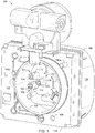
- FIG. 1 shows a valve controller 100 that includes example flame arrestors 101, 102, and 103.
- the example valve controller 100 may be used to control a position of a pneumatic or hydraulic valve utilized within a process control system.
- the valve controller 100 controls a desired valve by receiving a valve position via an electrical signal and converting the electrical signal into a corresponding pneumatic and/or hydraulic pressure.
- the valve controller 100 may include sensors, electrical circuitry, amplifiers, and/or converters in a feedback loop configuration to monitor and control the position of the valve.
- the example flame arrestors 101, 102 and 103 include respective plugs 104, 105, and 106 and passages and/or channels 112, 114, and 116.
- the plug 104 and the passage 112 form the first flame arrestor 101
- the plug 105 and the passage 114 form the second flame arrestor 102
- the plug 106 and the passage 116 form the third flame arrestor 103.
- the passages 112-116 are part of a module base, enclosure, housing, and/or a body 120 and provide a propagation path for fluid (e.g., a gas or a liquid) to pass from a first side 122 of the body 120 to a second side 124 of the body 120.
- the body 120 may be made of stainless steel, aluminum, and/or any other metal or hard plastic.
- the first side 122 of the body 120 shows the plugs 104-106 and the respective passages 112-116 within an electronics chamber 132.
- Electronics and/or sensors may be secured within the chamber 132 via a PCB such that the sensors may measure properties of a fluid that propagates through the passages 112-116.
- the first side 122 of the body 120 may be coupled to a valve housing (not shown) via connectors 140a-c.
- the connectors 140a-c may include bolts, screws, receiving holes, and/or any other connection component(s) to couple the body 120 to the valve housing.
- the valve housing covers the chamber 132, thereby covering the plugs 104-106, the passages 112-116, and the connectors 140a-c such that a partial seal is formed within the chamber 132.
- the second side 124 of the body 120 includes a cover 150 that houses relays, current-to-pressure converters (I/P converters), and/or pneumatic amplifiers.
- the second side 124 may also includes pressure gauges to display a pressure applied to a valve. These gauges are inside the cover 150 and, thus, the cover 150 may be made of a plastic that includes transparent sections to enable an operator to read the gauges through the cover 150. However, because the cover 150 may be made of plastic, the cover 150 may not form a seal against the second side 124 of the body 120. As a result, the cover 150 may not be functional and/or rated to contain a flame, fire, and/or explosion.
- pneumatic and/or hydraulic pressures controlled by regulators on the second side 124 of the body 120 are measured by electronics and/or sensors located on the first side 122 of the body 120.
- the electronics and/or sensors on the first side 122 are physically separated from the pressure regulators on the second side 124 to prevent any sparks and/or heat generated by the electronics from affecting the pressure regulators.
- a pressure of the fluid measured by the sensors propagates between the second side 124 and the first side 122 via the passages 112-116.
- one or more sensors on the first side 122 may additionally or alternatively measure other properties of a fluid including, chemical concentration, temperature, etc.
- the passages 112-116 include the respective plugs 104-106 to prevent any sparks, heat, flame etc. at the first side 122 from propagating to the second side 124.
- the example valve controller 100 of FIG. 1 may be located in and/or around a combustible environment.
- the valve controller 100 may be located at an oil refinery and control a valve through which oil flows.
- the valve controller 100 may be located in a process control environment that includes hazardous, toxic, and/or combustible chemicals.
- fumes, fluids, and/or chemicals may migrate into the valve controller 100 via the boundary between the cover 150 and the second side 124 of the body 120 and/or into the electronics chamber 132 via the partial seal between the first side 122 of the body 120 and the valve housing. In many instances these fumes, fluids, and/or chemicals may not pose a hazard to the normal operation of the valve controller 100.
- these fumes, fluids, and/or chemicals may ignite and cause a flame from a spark and/or heat generated by the electronics within the electronics chamber 132. If the flame is permitted to reach the highly combustive environment outside of the valve controller 100, the fire may ignite a larger more destructive fire in the combustible environment that results in widespread damage to the process plant and/or process control system.
- the chamber 132 directs the flame into the valve housing and away from the partial seal between the body 120 and the housing. Directing the flame into the valve housing prevents the flame from exiting the partial seal between the valve housing and the body 120 because the connectors 140a-c keep the valve housing coupled to the body 120 while the mass of the valve housing and/or the body 120 absorbs the heat associated with the flame.
- the passages 112-116 provide a possible flame propagation path to the second side 124 of the body 120. Because the cover 150 is not functional and/or rated to contain a flame, any flame that reaches the second side 124 of the body 120 is considered to reach the external combustible environment of the valve controller 100. In the examples described herein, the flame arrestors 101-103 prevent the propagation of the flame from the first side 122 to the second side 124.
- the example plugs 104-106 are disposed within the respective passages 112-116 to substantially fill a cross-sectional area of the passages 112-116.
- the plugs 104-106 have a diameter smaller than a diameter of the passages 112-116 such that a gap exists between the exterior surface of each of the plugs 104-106 and the wall of the respective one of the passages 112-116, which fluidly couple the second side 124 to the first side 122.
- Each of the plugs 104-106 has a first end that engages a shoulder within a respective one of the passages 112-116.
- each of the plugs 104-106 includes one or more slots that are aligned with a respective one of the passages 112-116 so that a fluid may propagate around or bypass the partial seal between the shoulder and the end of the plug and through the passage.
- the one or more slots direct fluid flow in the slot(s) toward the wall of the passage and along the gap between the exterior surface of the plug and the passage wall.
- FIG. 1 shows the valve controller 100 with the plugs 104-106
- the plugs 104, 104, and/or 106 may be used in other types of passages or channels that enable a fluid to pass from one side of a body to another side of the body but prevent a flame and/or explosion from propagating through the passage and/or channel.
- the valve controller 100 may include additional or fewer flame arrestors and/or passages.
- the passages 112-116 and the respective plugs 104-106 may be located at different locations on the body 120 than those depicted in FIG. 1 .
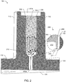
- FIG. 2 is a cross-sectional diagram of an example manner of implementing the flame arrestor 101 that includes the plug 104 and the passage 112 of FIG. 1 .
- the plug 104 is disposed within the passage 112, which includes a first end 202a and a second end 202b.
- the passage 112 extends between the first end 202a at the second side 124 of the body 120 and the second end 202b at the first side 122 of the body 120.
- the first end 202a of the passage 112 is relatively narrow or has a relatively small cross-sectional area up to a shoulder 204, at which point the passage 112 widens to accommodate the plug 104.
- a diameter of the passage 112 is substantially constant from the second end 202b of the passage to the shoulder 204 and decreases from the shoulder 204 toward the first end 202a of the passage 112.
- the first end 202a of the passage 112 may be relatively wider or the same width as the second end 202b.
- the plug 104 may have a length of 11.9 millimeters (mm) and a diameter of 3.9 mm. In other examples, the plug 104 may have a different length and/or diameter. Further, the plug 104 may be made of stainless steel (e.g., SST316) or aluminum alloy (e.g., A96061). In other examples, the plug 104 may be made of plastic and/or another other metal or metal alloy.
- the body 120 may be made of alloy steel (e.g., A360), stainless steel (e.g., CF8M) and/or any other type of metal, plastic, or metal alloy.
- the passage 112 may be drilled (e.g., cored) and/or etched into the body 120. In other examples, the plug 104, the passage 112 and/or the body 120 may be formed via metal injection molding, casting, machining, and/or any other metal forming process.
- An enlarged view 206 highlights the boundary of the plug 104 with the shoulder 204 to create a partial seal.
- the partial seal is created by the end of the plug 104 engaging the shoulder 204.
- the enlarged view 206 also shows that the plug 104 has a width (e.g., a diameter) that is less than the diameter of the passage 112 to provide a gap 210 between an outer surface 209 of the plug 104 and a wall 211 of the passage 112.
- the gap 210 enables a fluid to flow through the passage 112 between the wall 211 of the passage 112 and the exterior surface 209 of the plug 104.
- the gap 210 between the exterior surface 209 of the plug 104 and the wall 211 of the passage 112 may range from about 0.0001 mm to 2.0 mm or 0.05% to 10% of a diameter of the plug 104. In other examples, the gap 210 may range from a few millimeters to a few centimeters. The gap 210 may be a few centimeters wide in applications that require a relatively long and wide passage. In some examples, the gap 210 may exist between the entire exterior surface 209 of the plug 104 and the wall 211 of the passage 112. In other examples, the gap 210 may exist between only a portion of the exterior surface 209 of the plug 104 and the wall 211 of the passage 112 such that fluid may still propagate from the first end 202a to the second end 202b of the passage 112.
- the enlarged view 206 also shows a slot 212 at a first end of the plug 104.
- the example slot 212 may be aligned with the first end 202a of the passage 112 such that a fluid may flow into the slot 212 and then into the gap 210 where the slot 212 prevents the end of the plug 104 from engaging (e.g., sealing against) the shoulder 204.
- the example slot 212 is shown as having a rectangular shape that extends a distance into the plug 104 such that fluid from the first end 202a of the passage 112 can propagate (as shown by the arrows) into the slot 212 to bypass the partial seal of the plug 104 at the shoulder 204.
- the fluid may then propagate from the slot 212 through the passage 112 via the gap 210 to the second end 202b.
- the example slot 212 may extend across the entire diameter of the first end of the plug 104. While the example slot 212 is shown extending into the plug 104 at about 5% of the length of the plug 104, in other example the slot 212 may extend into the plug 104 from about 0.01% to 95% of the length of the plug 104.
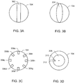
- FIG. 3 shows other example dimensions, geometries, and shapes that may be used to implement the slot 212.
- the example plug 104 is secured to the passage 112 via connections 220 and 222. Securing the plug 104 prevents the plug 104 from becoming misaligned with the first end 202a of the passage 112 and/or becoming dislodged from the passage 112 during movement and/or during an arresting of a flame.
- the connections 220 and 222 may include stakes at the second end 202b of the passage 112.
- the connections 220 and 222 may additionally or alternatively be implemented using tabs that engage apertures by welding a portion of a second end of the plug 104 to the passage 112.
- the plug 104 may be secured to the passage 112 by crimping the second end of the plug 104 to the shoulder 204.
- the example flame arrestor 101 of FIG. 2 prevents a flame from propagating from the second end 202b to the first end 202a of the passage 112 by directing the flame into the gap 210. Because the gap 210 is relatively narrow or small compared to the length of the passage 112, the length of plug 104, the surface area of the exterior surface 209 of the plug 104, and the surface area of the wall 211 of the passage 112, heat associated with the flame is readily absorbed by the plug 104 and the wall 211 of the passage 112 before the flame can reach the first end 202a.
- the dimensions, geometry, and/or shape of the slot 212 may be constructed to further absorb heat by directing the flame into the slot 212.
- the plug 104 may also prevent a flame from propagating from the first end 202a to the second end 202b of the passage 112 by restricting the propagation of the flame to the slot 212 and the relatively narrow gap 210.
- example plug 104 is shown in FIG. 2 , other shapes, geometries, and/or dimensions to fit within differently shaped and/or dimensioned passages may be used instead. Further, other plugs configurations may include other structures, indentions, and/or holes based on properties of a passage to provide fluid flow while restricting the propagation of a flame. Still further, the example flame arrestor 101 of FIG. 2 may be used to implement the flame arrestors 102 and 103 of FIG. 1 . Alternatively, any other configuration(s) may be used to implement the flame arrestors 101-103.
- FIGS. 3A-3D are example cross-sectional diagrams of example manners of implementing the plug 104 of FIG. 2 . While FIGS. 3A-3D show example slots 302, 304, 306a-I, and 308 that may be formed at a first end of the plug 104, other slots of varying dimensions, shapes, and/or geometries may be formed on the plug 104. For example, additional slots may be shaped like triangles, pentagons, hexagons, etc. Additionally, the plug 104 may include other slots that may have varying depths or include a varying numbers of slots.
- FIG. 3A shows a cross-section of the first end of the example plug 104 with the slot 302.
- the example slot 302 is rectangular in shape and extends across the diameter of the first end of the plug 104 to intersect the outer peripheral or circumference of the plug 104.
- fluid propagates from inside the slot 302 to the edge of the slot 302 at the circumference of the plug 104. The fluid may then propagate along the outer surface of the plug 104.
- FIG. 3B shows a cross-section of the first end of the example plug 104 with the slot 304.
- the example slot 304 is similar to the slot 302 but has an elliptical shape that extends a distance into the plug 104 and has a major diameter substantially equal to a diameter of the plug 104.
- FIG. 3C shows a cross-section of the first end of the example plug 104 with the slots 306a-i, which are not according to the invention.
- the example slots 306a-i are rectangular in shape and extend along the face of the first of the plug 104 from inside the outer circumference to the outer circumference.
- fluid propagates via each of the slots 306a-i to the outer edge of the slots 306a-i at the circumference of the plug 104. The fluid may then propagate along the outer surface of the plug 104.
- FIG. 3D shows a cross-section of the first end of the example plug 104 with the slot 308, which is not according to the invention.
- the example slot 308 has a circular face and extends into the plug 104 in a conical shape.
- the slot 308 is fluidly coupled to the exterior surface of the plug 104 via an opening 310 and passage 312 though the plug 104.
- the example plug 104 may include additional passages at varying depths.
- fluid propagates from inside the slot 308 through the opening 310 and the passage 312 to the circumference of the plug 104. The fluid may then propagate along the outer surface of the plug 104.
Landscapes
- Health & Medical Sciences (AREA)
- Public Health (AREA)
- Business, Economics & Management (AREA)
- Emergency Management (AREA)
- Safety Valves (AREA)
- Gas Burners (AREA)
- Spark Plugs (AREA)
- Valve Housings (AREA)
- Feeding And Controlling Fuel (AREA)
- Fire-Extinguishing By Fire Departments, And Fire-Extinguishing Equipment And Control Thereof (AREA)
Applications Claiming Priority (2)
| Application Number | Priority Date | Filing Date | Title |
|---|---|---|---|
| US12/616,954 US8960320B2 (en) | 2009-11-12 | 2009-11-12 | Inline plug flame arrestors |
| PCT/US2010/053841 WO2011059676A1 (en) | 2009-11-12 | 2010-10-22 | Inline plug flame arrestors |
Publications (2)
| Publication Number | Publication Date |
|---|---|
| EP2498877A1 EP2498877A1 (en) | 2012-09-19 |
| EP2498877B1 true EP2498877B1 (en) | 2020-02-12 |
Family
ID=43513812
Family Applications (1)
| Application Number | Title | Priority Date | Filing Date |
|---|---|---|---|
| EP10771864.5A Active EP2498877B1 (en) | 2009-11-12 | 2010-10-22 | Inline plug flame arrestors |
Country Status (10)
| Country | Link |
|---|---|
| US (1) | US8960320B2 (ja) |
| EP (1) | EP2498877B1 (ja) |
| JP (1) | JP5775090B2 (ja) |
| CN (1) | CN102655913B (ja) |
| AR (1) | AR078965A1 (ja) |
| BR (1) | BR112012011295A2 (ja) |
| CA (1) | CA2780521C (ja) |
| MX (1) | MX2012005547A (ja) |
| RU (1) | RU2562498C2 (ja) |
| WO (1) | WO2011059676A1 (ja) |
Families Citing this family (17)
| Publication number | Priority date | Publication date | Assignee | Title |
|---|---|---|---|---|
| US8485040B2 (en) * | 2011-03-14 | 2013-07-16 | Rosemount Inc. | Flame arrestor for process transmitter |
| US9362336B2 (en) * | 2014-09-11 | 2016-06-07 | Qualcomm Incorporated | Sub-lithographic patterning of magnetic tunneling junction devices |
| US20160076507A1 (en) * | 2014-09-16 | 2016-03-17 | Cummins Inc. | Vented spark plug tube with flame arrestor |
| GB201508175D0 (en) * | 2015-05-13 | 2015-06-24 | Cambridge Sensor Technology Ltd | Methods and systems |
| US20160375285A1 (en) * | 2015-06-25 | 2016-12-29 | Tescom Corporation | Flame arrestor assembly |
| US10197181B2 (en) * | 2015-06-25 | 2019-02-05 | Tescom Corporation | Non-inert gas certified electronic controller |
| WO2016210394A1 (en) * | 2015-06-25 | 2016-12-29 | Tescom Corporation | Flush-mount npt plug |
| WO2017004479A1 (en) * | 2015-07-01 | 2017-01-05 | Tescom Corporation | Explosion resistant electro-pneumatic controller |
| US10385879B2 (en) * | 2016-06-27 | 2019-08-20 | Tescom Corporation | Explosion resistant electro-pneumatic controller |
| EP3322902B1 (de) * | 2015-07-15 | 2019-06-12 | Basf Se | Ejektordüse und verwendung der ejektordüse |
| DE102015121629A1 (de) * | 2015-12-11 | 2017-06-14 | Endress + Hauser Gmbh + Co. Kg | Druckmessaufnehmer mit Flammendurchschlagsperre |
| DE102016212612B4 (de) * | 2016-07-11 | 2020-01-30 | Minimax Gmbh & Co. Kg | Feuerlöschvorrichtung zur Installation in einem Raum und zur Brandbekämpfung in mehreren Sektoren des Raums, sowie Feuerlöschanlage mit selbiger |
| DE112017006504T5 (de) | 2016-12-22 | 2020-04-23 | Cps Technology Holdings Llc | Ventilanordnung für eine batterieabdeckung |
| EP3635805B1 (en) | 2017-06-09 | 2023-09-06 | CPS Technology Holdings LLC | Lead-acid battery |
| US11936032B2 (en) | 2017-06-09 | 2024-03-19 | Cps Technology Holdings Llc | Absorbent glass mat battery |
| US11852152B2 (en) | 2019-10-07 | 2023-12-26 | The Gorman-Rupp Company | Pin vent assembly |
| CN113018731A (zh) * | 2021-04-01 | 2021-06-25 | 孙祥淇 | 一种分散气流防爆炸的阻火器 |
Citations (1)
| Publication number | Priority date | Publication date | Assignee | Title |
|---|---|---|---|---|
| EP1608941A1 (de) * | 2003-04-01 | 2005-12-28 | Endress + Hauser GmbH + Co. KG | Druckaufnehmer mit flammendurchschlagsperre |
Family Cites Families (26)
| Publication number | Priority date | Publication date | Assignee | Title |
|---|---|---|---|---|
| US1688585A (en) * | 1928-10-23 | op baltimore | ||
| US1449949A (en) * | 1920-09-24 | 1923-03-27 | Clara B Mcdole | Paint-spraying nozzle |
| US3100084A (en) * | 1961-08-01 | 1963-08-06 | Gulf Research Development Co | Constant flow rate fuel injection nozzle |
| US4072799A (en) * | 1977-04-13 | 1978-02-07 | Esb Incorporated | Vent plug system for batteries |
| JPS5417534A (en) | 1977-07-08 | 1979-02-08 | Koatsu Gas Kogyo | Antibackfire device for explosive gas |
| SU825101A1 (ru) * | 1978-12-18 | 1981-04-30 | Предприятие П/Я В-8116 | ПЛАМЕГАСИТЕЛЬ ДЛЯ ВСПОМОГАТЕЛЬНЫХ СИСТЕМ ЭНЕРГЕТИЧЕСКИХ УСТАНОВОКдвигателей внутреннего сгорани и дренажных системах изделий с повьшенны- ми требовани ми к обеспечению пожа- ро^взрывобезопасности.Актуальность решаемой задачи обусловлена тем, что, высокотемпературные продукты сгорани имеют в своем составе твердые^гор чие частицы размером больше 1 мкм, представл ющие собой м гкий углеродистый материал или (в основном у твердых топлив) раскаленные, сильно эродирующие включени . Такие включени могут пред— •ставл ть опасность, например в авиа-1015201Изобретение относитс к противопо"- жарной технике , в частности к пламегасител м, и может примен тьс преимущественно во вспомогательных системах энергетических установок с использованием продуктов сгорани твердых, жидких и газообразных топлив или газа, отбираемого из дерного реактора,- например в авиации, знергомашиност- роении, а также в выхлопных системахции, в пожаровзрывобезопасном отношении при дренаже, использовании в рабочем органе, а также при воздействии на различные конструктивные элементы вспомогательных систем (лопатки турбины, расходомеры, дроссели, мембраны, уплотнени и др.).Известен глушитель с искрогасителем, в котором газ до попадани в искрогаситель получает сильную закрутку [Q.Недостатками известного пламегасител вл ютс : неравномерное охлаждение 1по живому сечению газового потока и возможность проскакивани твердых раскаленных частиц, содержащихс в газе, через глушитель; возможность попадани в газ твердых раскаленных частиц из искрогас щего материала]^ сравнительно большое сопротивление гидравлического тракта.Наиболее близким к предлагаемому - вл етс пламегаситель, содержащий •ко^)пус с входным и выходным каналами. |
| US4317868A (en) * | 1980-09-19 | 1982-03-02 | Gould Inc. | Battery vent plug with flame arrestor |
| US4474331A (en) * | 1982-09-27 | 1984-10-02 | Wm. Steinen Mfg. Co. | Recessed center vane for full cone nozzle |
| DE3538089A1 (de) * | 1985-10-25 | 1987-04-30 | Kraftwerk Union Ag | Verfahren und einrichtung zum spuelen der innenoberflaeche eines rohres im bereich einer schweissnaht |
| US4785158A (en) * | 1987-03-25 | 1988-11-15 | Dresser Industries, Inc. | Flame arrestor and method of manufacture |
| US5794707A (en) * | 1988-12-06 | 1998-08-18 | Alhamad; Shaikh Ghaleb Mohammad Yassin | Flame arrestor |
| US4970898A (en) * | 1989-09-20 | 1990-11-20 | Rosemount Inc. | Pressure transmitter with flame isolating plug |
| DE69305351T3 (de) * | 1992-06-30 | 2002-11-21 | Comb Controls Inc | Flammen- und explosionsschutzsicherung |
| JPH06313525A (ja) | 1993-04-28 | 1994-11-08 | Koike Sanso Kogyo Co Ltd | 逆火防止器 |
| DE4338013C1 (de) | 1993-11-08 | 1995-04-20 | Sicherungsgeraetebau Gmbh | Flammendurchschlagsicherung für Rohrleitungen |
| WO1996034264A1 (en) * | 1995-04-28 | 1996-10-31 | Rosemount Inc. | Pressure transmitter with high pressure isolator mounting assembly |
| US5713205A (en) * | 1996-08-06 | 1998-02-03 | General Electric Co. | Air atomized discrete jet liquid fuel injector and method |
| US5948988A (en) * | 1998-05-27 | 1999-09-07 | Honeywell Inc | Pressure transducer with flame arrester |
| US6283387B1 (en) * | 1998-10-27 | 2001-09-04 | Nathan Palestrant | Misting head poppet |
| EP1211738B1 (de) * | 2000-11-29 | 2006-03-08 | VB Autobatterie GmbH & Co. KGaA. | Verschlussstopfenanordnung für Akkumulatoren |
| JP3627217B2 (ja) | 2002-01-18 | 2005-03-09 | ケービーエンテク株式会社 | ブラウンガス燃焼用バーナー |
| US6799984B2 (en) * | 2002-05-31 | 2004-10-05 | Mine Safety Appliances Company | Connectors, instrument assemblies and methods of connecting or disconnecting electrical connections under power |
| US7198201B2 (en) * | 2002-09-09 | 2007-04-03 | Bete Fog Nozzle, Inc. | Swirl nozzle and method of making same |
| JP4154317B2 (ja) * | 2003-04-25 | 2008-09-24 | トヨタ自動車株式会社 | 燃料噴射弁 |
| JP2005127583A (ja) | 2003-10-23 | 2005-05-19 | Hayashi Shinichiro | 逆火防止ガストーチ |
| DE102004042835B3 (de) | 2004-09-03 | 2006-03-16 | Eberhard Grabs | Flammendurchschlagsicherung mit flammenlöschenden Spalten |
-
2009
- 2009-11-12 US US12/616,954 patent/US8960320B2/en active Active
-
2010
- 2010-10-22 RU RU2012122363/12A patent/RU2562498C2/ru active
- 2010-10-22 MX MX2012005547A patent/MX2012005547A/es active IP Right Grant
- 2010-10-22 CA CA2780521A patent/CA2780521C/en active Active
- 2010-10-22 BR BR112012011295A patent/BR112012011295A2/pt not_active IP Right Cessation
- 2010-10-22 CN CN201080057639.3A patent/CN102655913B/zh active Active
- 2010-10-22 JP JP2012538833A patent/JP5775090B2/ja not_active Expired - Fee Related
- 2010-10-22 WO PCT/US2010/053841 patent/WO2011059676A1/en active Application Filing
- 2010-10-22 EP EP10771864.5A patent/EP2498877B1/en active Active
- 2010-11-10 AR ARP100104172A patent/AR078965A1/es not_active Application Discontinuation
Patent Citations (1)
| Publication number | Priority date | Publication date | Assignee | Title |
|---|---|---|---|---|
| EP1608941A1 (de) * | 2003-04-01 | 2005-12-28 | Endress + Hauser GmbH + Co. KG | Druckaufnehmer mit flammendurchschlagsperre |
Also Published As
| Publication number | Publication date |
|---|---|
| AR078965A1 (es) | 2011-12-14 |
| CN102655913A (zh) | 2012-09-05 |
| BR112012011295A2 (pt) | 2017-10-10 |
| EP2498877A1 (en) | 2012-09-19 |
| RU2012122363A (ru) | 2013-12-20 |
| CN102655913B (zh) | 2015-08-12 |
| RU2562498C2 (ru) | 2015-09-10 |
| WO2011059676A1 (en) | 2011-05-19 |
| JP2013510648A (ja) | 2013-03-28 |
| US8960320B2 (en) | 2015-02-24 |
| CA2780521C (en) | 2017-09-12 |
| US20110108292A1 (en) | 2011-05-12 |
| JP5775090B2 (ja) | 2015-09-09 |
| CA2780521A1 (en) | 2011-05-19 |
| MX2012005547A (es) | 2012-08-03 |
Similar Documents
| Publication | Publication Date | Title |
|---|---|---|
| EP2498877B1 (en) | Inline plug flame arrestors | |
| JP2804173B2 (ja) | 炎遮断プラグを備えた圧力トランスミッタ | |
| JP4046508B2 (ja) | 圧力センサモジュール | |
| KR101503705B1 (ko) | 양압형 방폭장치 | |
| EP1595124B1 (en) | Gauge pressure sensor hazardous applications | |
| JP2006334064A (ja) | 自動消火デバイス | |
| JP2001298280A (ja) | ケーシングを備えた電子装置 | |
| EP3461538B1 (en) | Flame arrestor with fluid drainage capabilities | |
| KR101118618B1 (ko) | 고체에어로졸 소화장치용 기동부 | |
| CN113494681B (zh) | 流体压力控制装置 | |
| US20160375285A1 (en) | Flame arrestor assembly | |
| KR101134359B1 (ko) | 고체에어로졸 소화장치 | |
| JP3618694B2 (ja) | 耐圧防爆電気装置 | |
| CN104864167B (zh) | 暴露外壳标签的方法及装置 | |
| US11752372B2 (en) | Ignition suppressing enclosure having vent paths for flame quenching | |
| JP6316563B2 (ja) | 消火ガス発生装置 | |
| KR20220126406A (ko) | 방폭 구조를 갖는 자동소화장치 및 그 제어방법 | |
| KR200294318Y1 (ko) | 휴대형 방폭용 접지 접속장치 | |
| KR101577290B1 (ko) | 미압 인식용 압력 스위치 | |
| CN116133311A (zh) | 一种用于易燃易爆环境的防爆主机箱 | |
| KR20240006301A (ko) | 전기자동차의 배터리팩 소화장치 | |
| KR20220169282A (ko) | 최고 표면 온도를 제한하는 방폭 솔레노이드 밸브 및 이를 포함하는 연료 공급 시스템 | |
| CN118016570A (zh) | 半导体防护装置和半导体工艺设备 | |
| JP2000195579A (ja) | 防爆型電気継手装置 | |
| Tyldesley | Explosion prevention-the broader picture |
Legal Events
| Date | Code | Title | Description |
|---|---|---|---|
| PUAI | Public reference made under article 153(3) epc to a published international application that has entered the european phase |
Free format text: ORIGINAL CODE: 0009012 |
|
| 17P | Request for examination filed |
Effective date: 20120509 |
|
| AK | Designated contracting states |
Kind code of ref document: A1 Designated state(s): AL AT BE BG CH CY CZ DE DK EE ES FI FR GB GR HR HU IE IS IT LI LT LU LV MC MK MT NL NO PL PT RO RS SE SI SK SM TR |
|
| DAX | Request for extension of the european patent (deleted) | ||
| STAA | Information on the status of an ep patent application or granted ep patent |
Free format text: STATUS: EXAMINATION IS IN PROGRESS |
|
| 17Q | First examination report despatched |
Effective date: 20171018 |
|
| GRAP | Despatch of communication of intention to grant a patent |
Free format text: ORIGINAL CODE: EPIDOSNIGR1 |
|
| STAA | Information on the status of an ep patent application or granted ep patent |
Free format text: STATUS: GRANT OF PATENT IS INTENDED |
|
| INTG | Intention to grant announced |
Effective date: 20190829 |
|
| GRAS | Grant fee paid |
Free format text: ORIGINAL CODE: EPIDOSNIGR3 |
|
| GRAA | (expected) grant |
Free format text: ORIGINAL CODE: 0009210 |
|
| STAA | Information on the status of an ep patent application or granted ep patent |
Free format text: STATUS: THE PATENT HAS BEEN GRANTED |
|
| AK | Designated contracting states |
Kind code of ref document: B1 Designated state(s): AL AT BE BG CH CY CZ DE DK EE ES FI FR GB GR HR HU IE IS IT LI LT LU LV MC MK MT NL NO PL PT RO RS SE SI SK SM TR |
|
| REG | Reference to a national code |
Ref country code: GB Ref legal event code: FG4D |
|
| REG | Reference to a national code |
Ref country code: CH Ref legal event code: EP |
|
| REG | Reference to a national code |
Ref country code: AT Ref legal event code: REF Ref document number: 1231307 Country of ref document: AT Kind code of ref document: T Effective date: 20200215 |
|
| REG | Reference to a national code |
Ref country code: DE Ref legal event code: R096 Ref document number: 602010063042 Country of ref document: DE |
|
| REG | Reference to a national code |
Ref country code: IE Ref legal event code: FG4D |
|
| PG25 | Lapsed in a contracting state [announced via postgrant information from national office to epo] |
Ref country code: NO Free format text: LAPSE BECAUSE OF FAILURE TO SUBMIT A TRANSLATION OF THE DESCRIPTION OR TO PAY THE FEE WITHIN THE PRESCRIBED TIME-LIMIT Effective date: 20200512 Ref country code: FI Free format text: LAPSE BECAUSE OF FAILURE TO SUBMIT A TRANSLATION OF THE DESCRIPTION OR TO PAY THE FEE WITHIN THE PRESCRIBED TIME-LIMIT Effective date: 20200212 Ref country code: RS Free format text: LAPSE BECAUSE OF FAILURE TO SUBMIT A TRANSLATION OF THE DESCRIPTION OR TO PAY THE FEE WITHIN THE PRESCRIBED TIME-LIMIT Effective date: 20200212 |
|
| REG | Reference to a national code |
Ref country code: LT Ref legal event code: MG4D |
|
| REG | Reference to a national code |
Ref country code: NL Ref legal event code: MP Effective date: 20200212 |
|
| PG25 | Lapsed in a contracting state [announced via postgrant information from national office to epo] |
Ref country code: GR Free format text: LAPSE BECAUSE OF FAILURE TO SUBMIT A TRANSLATION OF THE DESCRIPTION OR TO PAY THE FEE WITHIN THE PRESCRIBED TIME-LIMIT Effective date: 20200513 Ref country code: HR Free format text: LAPSE BECAUSE OF FAILURE TO SUBMIT A TRANSLATION OF THE DESCRIPTION OR TO PAY THE FEE WITHIN THE PRESCRIBED TIME-LIMIT Effective date: 20200212 Ref country code: SE Free format text: LAPSE BECAUSE OF FAILURE TO SUBMIT A TRANSLATION OF THE DESCRIPTION OR TO PAY THE FEE WITHIN THE PRESCRIBED TIME-LIMIT Effective date: 20200212 Ref country code: LV Free format text: LAPSE BECAUSE OF FAILURE TO SUBMIT A TRANSLATION OF THE DESCRIPTION OR TO PAY THE FEE WITHIN THE PRESCRIBED TIME-LIMIT Effective date: 20200212 Ref country code: BG Free format text: LAPSE BECAUSE OF FAILURE TO SUBMIT A TRANSLATION OF THE DESCRIPTION OR TO PAY THE FEE WITHIN THE PRESCRIBED TIME-LIMIT Effective date: 20200512 Ref country code: IS Free format text: LAPSE BECAUSE OF FAILURE TO SUBMIT A TRANSLATION OF THE DESCRIPTION OR TO PAY THE FEE WITHIN THE PRESCRIBED TIME-LIMIT Effective date: 20200612 |
|
| PG25 | Lapsed in a contracting state [announced via postgrant information from national office to epo] |
Ref country code: NL Free format text: LAPSE BECAUSE OF FAILURE TO SUBMIT A TRANSLATION OF THE DESCRIPTION OR TO PAY THE FEE WITHIN THE PRESCRIBED TIME-LIMIT Effective date: 20200212 |
|
| PG25 | Lapsed in a contracting state [announced via postgrant information from national office to epo] |
Ref country code: RO Free format text: LAPSE BECAUSE OF FAILURE TO SUBMIT A TRANSLATION OF THE DESCRIPTION OR TO PAY THE FEE WITHIN THE PRESCRIBED TIME-LIMIT Effective date: 20200212 Ref country code: CZ Free format text: LAPSE BECAUSE OF FAILURE TO SUBMIT A TRANSLATION OF THE DESCRIPTION OR TO PAY THE FEE WITHIN THE PRESCRIBED TIME-LIMIT Effective date: 20200212 Ref country code: EE Free format text: LAPSE BECAUSE OF FAILURE TO SUBMIT A TRANSLATION OF THE DESCRIPTION OR TO PAY THE FEE WITHIN THE PRESCRIBED TIME-LIMIT Effective date: 20200212 Ref country code: SM Free format text: LAPSE BECAUSE OF FAILURE TO SUBMIT A TRANSLATION OF THE DESCRIPTION OR TO PAY THE FEE WITHIN THE PRESCRIBED TIME-LIMIT Effective date: 20200212 Ref country code: LT Free format text: LAPSE BECAUSE OF FAILURE TO SUBMIT A TRANSLATION OF THE DESCRIPTION OR TO PAY THE FEE WITHIN THE PRESCRIBED TIME-LIMIT Effective date: 20200212 Ref country code: DK Free format text: LAPSE BECAUSE OF FAILURE TO SUBMIT A TRANSLATION OF THE DESCRIPTION OR TO PAY THE FEE WITHIN THE PRESCRIBED TIME-LIMIT Effective date: 20200212 Ref country code: SK Free format text: LAPSE BECAUSE OF FAILURE TO SUBMIT A TRANSLATION OF THE DESCRIPTION OR TO PAY THE FEE WITHIN THE PRESCRIBED TIME-LIMIT Effective date: 20200212 Ref country code: ES Free format text: LAPSE BECAUSE OF FAILURE TO SUBMIT A TRANSLATION OF THE DESCRIPTION OR TO PAY THE FEE WITHIN THE PRESCRIBED TIME-LIMIT Effective date: 20200212 Ref country code: PT Free format text: LAPSE BECAUSE OF FAILURE TO SUBMIT A TRANSLATION OF THE DESCRIPTION OR TO PAY THE FEE WITHIN THE PRESCRIBED TIME-LIMIT Effective date: 20200705 |
|
| REG | Reference to a national code |
Ref country code: DE Ref legal event code: R097 Ref document number: 602010063042 Country of ref document: DE |
|
| REG | Reference to a national code |
Ref country code: AT Ref legal event code: MK05 Ref document number: 1231307 Country of ref document: AT Kind code of ref document: T Effective date: 20200212 |
|
| PLBE | No opposition filed within time limit |
Free format text: ORIGINAL CODE: 0009261 |
|
| STAA | Information on the status of an ep patent application or granted ep patent |
Free format text: STATUS: NO OPPOSITION FILED WITHIN TIME LIMIT |
|
| 26N | No opposition filed |
Effective date: 20201113 |
|
| PG25 | Lapsed in a contracting state [announced via postgrant information from national office to epo] |
Ref country code: IT Free format text: LAPSE BECAUSE OF FAILURE TO SUBMIT A TRANSLATION OF THE DESCRIPTION OR TO PAY THE FEE WITHIN THE PRESCRIBED TIME-LIMIT Effective date: 20200212 Ref country code: AT Free format text: LAPSE BECAUSE OF FAILURE TO SUBMIT A TRANSLATION OF THE DESCRIPTION OR TO PAY THE FEE WITHIN THE PRESCRIBED TIME-LIMIT Effective date: 20200212 |
|
| PG25 | Lapsed in a contracting state [announced via postgrant information from national office to epo] |
Ref country code: PL Free format text: LAPSE BECAUSE OF FAILURE TO SUBMIT A TRANSLATION OF THE DESCRIPTION OR TO PAY THE FEE WITHIN THE PRESCRIBED TIME-LIMIT Effective date: 20200212 Ref country code: SI Free format text: LAPSE BECAUSE OF FAILURE TO SUBMIT A TRANSLATION OF THE DESCRIPTION OR TO PAY THE FEE WITHIN THE PRESCRIBED TIME-LIMIT Effective date: 20200212 |
|
| REG | Reference to a national code |
Ref country code: DE Ref legal event code: R119 Ref document number: 602010063042 Country of ref document: DE |
|
| REG | Reference to a national code |
Ref country code: CH Ref legal event code: PL |
|
| PG25 | Lapsed in a contracting state [announced via postgrant information from national office to epo] |
Ref country code: MC Free format text: LAPSE BECAUSE OF FAILURE TO SUBMIT A TRANSLATION OF THE DESCRIPTION OR TO PAY THE FEE WITHIN THE PRESCRIBED TIME-LIMIT Effective date: 20200212 Ref country code: LU Free format text: LAPSE BECAUSE OF NON-PAYMENT OF DUE FEES Effective date: 20201022 |
|
| REG | Reference to a national code |
Ref country code: BE Ref legal event code: MM Effective date: 20201031 |
|
| PG25 | Lapsed in a contracting state [announced via postgrant information from national office to epo] |
Ref country code: DE Free format text: LAPSE BECAUSE OF NON-PAYMENT OF DUE FEES Effective date: 20210501 |
|
| PG25 | Lapsed in a contracting state [announced via postgrant information from national office to epo] |
Ref country code: LI Free format text: LAPSE BECAUSE OF NON-PAYMENT OF DUE FEES Effective date: 20201031 Ref country code: BE Free format text: LAPSE BECAUSE OF NON-PAYMENT OF DUE FEES Effective date: 20201031 Ref country code: CH Free format text: LAPSE BECAUSE OF NON-PAYMENT OF DUE FEES Effective date: 20201031 |
|
| PG25 | Lapsed in a contracting state [announced via postgrant information from national office to epo] |
Ref country code: IE Free format text: LAPSE BECAUSE OF NON-PAYMENT OF DUE FEES Effective date: 20201022 |
|
| PG25 | Lapsed in a contracting state [announced via postgrant information from national office to epo] |
Ref country code: TR Free format text: LAPSE BECAUSE OF FAILURE TO SUBMIT A TRANSLATION OF THE DESCRIPTION OR TO PAY THE FEE WITHIN THE PRESCRIBED TIME-LIMIT Effective date: 20200212 Ref country code: MT Free format text: LAPSE BECAUSE OF FAILURE TO SUBMIT A TRANSLATION OF THE DESCRIPTION OR TO PAY THE FEE WITHIN THE PRESCRIBED TIME-LIMIT Effective date: 20200212 Ref country code: CY Free format text: LAPSE BECAUSE OF FAILURE TO SUBMIT A TRANSLATION OF THE DESCRIPTION OR TO PAY THE FEE WITHIN THE PRESCRIBED TIME-LIMIT Effective date: 20200212 |
|
| PG25 | Lapsed in a contracting state [announced via postgrant information from national office to epo] |
Ref country code: MK Free format text: LAPSE BECAUSE OF FAILURE TO SUBMIT A TRANSLATION OF THE DESCRIPTION OR TO PAY THE FEE WITHIN THE PRESCRIBED TIME-LIMIT Effective date: 20200212 Ref country code: AL Free format text: LAPSE BECAUSE OF FAILURE TO SUBMIT A TRANSLATION OF THE DESCRIPTION OR TO PAY THE FEE WITHIN THE PRESCRIBED TIME-LIMIT Effective date: 20200212 |
|
| P01 | Opt-out of the competence of the unified patent court (upc) registered |
Effective date: 20230526 |
|
| PGFP | Annual fee paid to national office [announced via postgrant information from national office to epo] |
Ref country code: GB Payment date: 20230920 Year of fee payment: 14 |
|
| PGFP | Annual fee paid to national office [announced via postgrant information from national office to epo] |
Ref country code: FR Payment date: 20230920 Year of fee payment: 14 |