EP1595124B1 - Gauge pressure sensor hazardous applications - Google Patents
Gauge pressure sensor hazardous applications Download PDFInfo
- Publication number
- EP1595124B1 EP1595124B1 EP03781900A EP03781900A EP1595124B1 EP 1595124 B1 EP1595124 B1 EP 1595124B1 EP 03781900 A EP03781900 A EP 03781900A EP 03781900 A EP03781900 A EP 03781900A EP 1595124 B1 EP1595124 B1 EP 1595124B1
- Authority
- EP
- European Patent Office
- Prior art keywords
- pressure
- sensor
- housing
- flame
- process fluid
- Prior art date
- Legal status (The legal status is an assumption and is not a legal conclusion. Google has not performed a legal analysis and makes no representation as to the accuracy of the status listed.)
- Expired - Lifetime
Links
Images

Classifications
-
- A—HUMAN NECESSITIES
- A62—LIFE-SAVING; FIRE-FIGHTING
- A62C—FIRE-FIGHTING
- A62C4/00—Flame traps allowing passage of gas but not of flame or explosion wave
-
- G—PHYSICS
- G01—MEASURING; TESTING
- G01L—MEASURING FORCE, STRESS, TORQUE, WORK, MECHANICAL POWER, MECHANICAL EFFICIENCY, OR FLUID PRESSURE
- G01L19/00—Details of, or accessories for, apparatus for measuring steady or quasi-steady pressure of a fluent medium insofar as such details or accessories are not special to particular types of pressure gauges
- G01L19/06—Means for preventing overload or deleterious influence of the measured medium on the measuring device or vice versa
- G01L19/0627—Protection against aggressive medium in general
- G01L19/0636—Protection against aggressive medium in general using particle filters
-
- G—PHYSICS
- G01—MEASURING; TESTING
- G01L—MEASURING FORCE, STRESS, TORQUE, WORK, MECHANICAL POWER, MECHANICAL EFFICIENCY, OR FLUID PRESSURE
- G01L19/00—Details of, or accessories for, apparatus for measuring steady or quasi-steady pressure of a fluent medium insofar as such details or accessories are not special to particular types of pressure gauges
- G01L19/06—Means for preventing overload or deleterious influence of the measured medium on the measuring device or vice versa
- G01L19/0663—Flame protection; Flame barriers
-
- G—PHYSICS
- G01—MEASURING; TESTING
- G01L—MEASURING FORCE, STRESS, TORQUE, WORK, MECHANICAL POWER, MECHANICAL EFFICIENCY, OR FLUID PRESSURE
- G01L19/00—Details of, or accessories for, apparatus for measuring steady or quasi-steady pressure of a fluent medium insofar as such details or accessories are not special to particular types of pressure gauges
- G01L19/06—Means for preventing overload or deleterious influence of the measured medium on the measuring device or vice versa
- G01L19/0672—Leakage or rupture protection or detection
Definitions
- the present disclosure relates generally to pressure sensors and, more specifically, to pressure sensors for use in hazardous applications.
- Pressure sensors are commonly used to monitor and/or control the pressure and flow of process fluids such as, for example, oil, water, gases, etc.
- the pressure sensors are integral to a fluid flow regulator that is serially interposed in the process fluid flow path.
- the pressure sensors are integral to a monitoring device that does not perform a regulation function and that is appended to or serially interposed in the process fluid flow path.
- the RegFloTM family of flow monitoring devices provided by Fisher Controls International, Inc. (and in particular the RF100 series flow monitoring devices) may include an inlet pressure sensor, an outlet pressure sensor and an auxiliary pressure sensor, all of which may be integrally attached via a threaded engagement.
- combustible process fluids e.g., combustible gases
- explosion proof or flame proof rated regulators sensing devices, etc.
- combustible process fluids that accumulate in the regulator housing must be properly vented to ambient or atmosphere to achieve a flame proof or explosion proof rating.
- atmospheric venting is configured to prevent the dangerous accumulation of combustible process fluids within the regulator housing and to prevent a combustion process that initiates within the regulator housing from propagating to the greater process ambient surrounding the regulator.
- sintered metal flame arrestors which are semi-porous and provide a sufficiently minimal flame path
- absolute pressure sensors usually include a diaphragm that deflects in proportion to the pressure difference across opposing faces of the diaphragm.
- a reference face or side of the diaphragm is exposed to a sealed chamber while the other side or face of the diaphragm is exposed to the pressure exerted by the process fluid being measured. Because the reference face or side of an absolute pressure sensor diaphragm does not have to be vented to atmosphere, it is a relatively simple matter to attach such a sensor to a regulator or monitor housing without compromising the explosion proof or flame proof rating of the regulator or monitor.
- absolute pressure sensors are not ideally suited for use in applications that require the measurement of low pressure process fluids such as, for example, natural gas distribution applications.
- absolute pressure sensors are typically only capable of accurately sensing pressures that are well above one atmosphere (i.e., about 15 pounds per square inch absolute).
- gauge pressure sensors are better suited to accurately measure relatively low pressures.
- the reference face or side of the diaphragm within a gauge pressure sensor must be vented to atmosphere.
- gauge pressure sensors it is not a simple matter to substitute gauge pressure sensors for the absolute pressure sensors that are typically used with explosion proof or flame proof regulators and monitors without compromising the explosion proof or flame proof rating of these devices.
- gauge pressure sensors are typically vented to atmosphere via a small opening in the sensor housing that is exposed to the ambient surrounding the sensor and the regulator or monitor with which it is associated.
- gauge pressure sensors typically cannot be used in regulator and/or monitor applications that result in submersion of the regulator and/or monitor in a liquid (e.g., water).
- a liquid e.g., water
- many underground applications may involve periodic or continuous submersion of a regulator (and the devices such as sensors and the like attached thereto) in water.
- US patent N° 6 422 085 describes a flush-diaphragm relative pressure sensor wherein the reference air reaches its current dew point before getting into the interior of the housing.
- the sensor has a capacitive, resistive, or piezoelectric sensing element with a diaphragm an external surface of which comes into direct contact with a medium under pressure.
- a housing has an interior space and a front portion open across the interior space in the vicinity of which the diaphragm closes the interior space such that the front portion projects beyond the diaphragm. Further, the housing has a bore extending through the front portion from an outer side thereof to the interior space for guiding the reference air. The bore is closed from the outer side with an open-pore, highly heat-conducting and hydrophobic filter, so that the filter and the diaphragm are at the same or nearly the same temperature.
- the filter can be made of a sintered metal, e.g.
- US patent N° 4 970 898 discloses a transmitter that provides an output indicating pressure difference between a line pressure and atmosphere outside the transmitter is made intrinsically safe by coupling the sensor cavity as well as other cavities where ignition can occur to atmosphere only through flame quenching paths.
- the opening in the transmitter housing in which the sensor is mounted has a plug including a sensor cavity that holds the sensor, and a fitting which is couplable to the pressure line.
- An isolator is used for transmitting the process pressure to the sensor through an isolator diaphragm acting on an incompressible filling the sensor cavity and transmitting pressure through a hole that is shaped to provide a flame quenching path.
- the passageway flame isolates the sensor from the process fluid line.
- the opposite side of the sensor is connected to atmosphere only through paths which are flame quenching because of the passageway shape.
- the plug is an assembly that can be made easily inserted and removed, and provides intrinsic safety even if there is failure of some of the components such as the isolating diaphragm or welds holding portions of the plug together.
- embodiments of the invention provide a pressure sensor as defined in claim 1.
- embodiments of the invention provide a pressure sensor as defined in claim 10.
- Fig. 1 is a sectional view of a know absolute pressure sensor assembly that may be used with explosion proof devices.
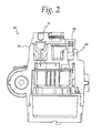
- Fig. 2 is a sectional view of a known explosion proof assembly having the absolute pressure sensor assembly shown in Fig. 1 mounted thereto.
- Fig. 3 is a sectional view of an example explosion proof assembly having an example gauge pressure sensor assembly mounted thereto.
- Fig. 1 is a sectional view of a known absolute pressure sensor assembly 10 that may be used with explosion proof devices.
- the pressure sensor assembly 10 includes a cylindrical sensor housing 12, a sensor sub-assembly 14, a plurality of electrical connections 16 that convey electrical signals to/from the sensor sub-assembly 14 and a grommet or strain relief plug 18 that provides strain relief for the electrical connections 16 as they exit the sensor housing 12.
- the strain relief plug 18 may be used to form a seal that prevents the ingress or egress of process fluids and/or other contaminants into or out of the sensor housing 12.
- the sensor sub-assembly 14 includes an input port or adapter 20, an o-ring or other circumferential seal 22 and a pressure sensing element 24.
- the input port or adapter 20 may be threaded or pressed into the housing 12 and may include internal threads 26 for connecting the sensor assembly 10 to a process fluid.
- the input port or adapter 20 is configured to communicate or convey a pressure associated with the process fluid to the pressure sensing element 24.
- the o-ring or other circumferential seal 22 is configured to prevent process fluids from bypassing the pressure sensing element 24 and thereby entering (or contaminating) a lower portion 28 of the sensor housing 12 and/or from contaminating a device to which the sensor assembly 10 is mounted.
- the pressure sensing element 24 may be a silicon-based absolute pressure sensor having a diaphragm that deflects or that is otherwise responsive to a pressure difference across opposing faces of the diaphragm. More specifically, the pressure sensing element 24 may provide a variable resistance and/or capacitance output in response to pressure variations across first and second faces 30 and 32 of the pressure sensing element 24. In particular, as depicted in Fig. 1 , the first face 30 of the pressure sensing element 24 is exposed to the process fluid via a passage 34. Although not shown, the second face 32 of the pressure sensing element 24 is exposed to a sealed internal chamber that is pressurized to about one atmosphere. Thus, as the pressure associated with the process fluid varies above one atmosphere of pressure, a resistance and/or capacitance associated with the pressure sensing element 24 varies and may be sensed via the electrical connections 16.
- Fig. 2 is a sectional view of a known explosion proof assembly 50 having the absolute pressure sensor assembly 10 shown in Fig. 1 mounted thereto.
- the explosion proof assembly 50 shown in Fig. 2 may be process fluid flow regulator and/or monitoring device that regulates and/or monitors the pressure and/or flow of a potentially explosive process fluid.
- the absolute pressure sensor assembly 10 is mounted to a housing portion 52 of the explosion proof assembly 50.
- the housing portion 52 is sealed with respect to its surrounding ambient and is vented through a flame arrestor 54 and an atmospheric vent or opening 56. In this manner, the combustion of any process fluids that accumulate within the housing portion 52 is prevented from propagating to the greater environment or ambient surrounding the explosion proof assembly 50.
- the pressure sensor assembly 10 is configured to detect or sense absolute pressure, the pressure sensor assembly 10 is sealed with respect to the housing portion 52 and, thus, potentially explosive process fluids do not accumulate within the pressure sensor assembly 10.
- Fig. 3 is a sectional view of an example explosion proof assembly 70 having an inner chamber 71 and an example gauge pressure sensor assembly 72 attached thereto.
- the example gauge pressure sensor assembly 72 includes a housing 74 having an input portion 76 and an attachment portion 78, a gauge pressure sensing element 80, a printed circuit assembly 82 and a flame arrestor 84.
- the input portion 76 of the housing 74 may include an internally threaded portion 86 that is configured to accommodate a 1 ⁇ 4 inch National Pipe Thread connection to a process fluid.
- an internally threaded portion 86 that is configured to accommodate a 1 ⁇ 4 inch National Pipe Thread connection to a process fluid.
- other connection mechanisms or connector configurations could be used instead.
- the input portion 76 of the housing 74 may provide a barbed fitting for use with flexible rubber or plastic tubing, a compression fitting for use with metal tubing and/or connectors, or any other desired coupling designed for use with process fluids.
- the attachment portion 78 of the housing 74 is generally cylindrically shaped and includes external threads 88 that enable the gauge pressure sensor assembly 72 to be threaded into an explosion proof housing 90, which may be associated with an explosion proof device such as, for example, a flow regulator and/or monitor for use with natural gas.
- an explosion proof device such as, for example, a flow regulator and/or monitor for use with natural gas.
- the attachment portion 78 does not necessarily have to provide a threaded engagement and the sensor assembly 72 could be attached to the explosion proof housing 90 in other manners.
- the attachment portion 78 could be configured for a press-fit, which may, if desired, include a crimp, stab-in, or other mechanical deformation of the housing 90 and/or the sensor housing 74 to fix the sensor assembly 72 to the explosion proof housing 90.
- the attachment portion 78 of the sensor housing 74 is preferably configured to mate with the explosion proof housing 90 to meet Canadian Standards Association (CSA) flame path requirements, which may, for example, require a maximum gap of 0.1 millimeter between the attachment portion 78 and the explosion proof housing 90.
- CSA Canadian Standards Association
- the sensor assembly housing 74 may also include a shoulder portion, collar or flange 92 that provides a mechanical stop against which the sensor assembly 72 can be tightened to the explosion proof housing 90.
- the shoulder portion 92 may also function to deform or otherwise seal against the explosion proof housing 90 to enable compliance with CSA flame path requirements.
- the gauge pressure sensing element 80 may be any desired gauge pressure sensing device including, for example, devices that are silicon-based and which use a variable resistance and/or capacitance output to detect the deflection of a diaphragm in response to variations in pressure.
- a first pressure inlet, face or side 94 of the sensing element 80 is exposed via openings 96 to a pressure associated with a process fluid.
- a second pressure inlet, face or side 98 of the pressure sensing element 80 is exposed to the internal pressure of the explosion proof housing 90, which is maintained at atmospheric ambient pressure via a second flame arrestor 100 and a vent 102.
- the pressure sensing element 80 may have electrical leads that are soldered directly to the printed circuit assembly 82 and a retaining mechanism 104 such as for example, a retaining ring, wave washer or spring, etc. may be used to retain the printed circuit assembly 82 and the pressure sensing element 80 within the housing 74 as shown.
- the pressure sensing element is a 0-3 pounds per square inch sensor when the pressure sensor assembly 72 is used in applications requiring the control and/or monitoring of relatively low pressures such as in natural gas distribution applications.
- the flame arrestor 84 is preferably, but not necessarily, cylindrically shaped and made of a sintered metal. However, other shapes and/or or materials could be used instead.
- the flame arrestor 84 is sized and configured to meet CSA flame path requirements (e.g., less than 0.1 millimeter gap along the length of the joint between the flame arrestor 84 and the housing 74.
- a plurality of flame proof electrical connections 106 pass through the flame arrestor 84 to enable electrical signals to be conveyed to/from the pressure sensing element 80.
- the electrical connections 106 pass through one or more openings or passages (not shown) in the flame arrestor 84 that may be glassed-in using any desired technique to achieve a flame proof rating.
- a second retaining ring 108 or other device may be used to fix or retain the flame arrestor 84 within the housing 74 as shown in Fig. 3 .
- a back up or back stop 110 may beprovided to provide overpressure protection in the event an explosion occurs within the housing 90.
- the back up 110 is preferably sized and configured to enable a diaphragm within the pressure sensing element 80 to withstand (i.e., to not punch through when subjected to) at least four times the rated explosion pressure of the housing 90.
- the example gauge pressure sensor assembly 72 depicted in Fig. 3 is fluidly coupled to a first pressure associated with a process fluid via, for example, the input portion 76 of the housing 74. Additionally, the gauge pressure sensor assembly 72 is fluidly coupled to atmospheric pressure via the flame arrestor 84, the sensor housing 90 and a second flame arrestor 100 and vent 102 associated with the housing 90. In this manner, a plurality of gauge pressure sensor assemblies such as that shown in Fig. 3 may be vented to atmospheric pressure through an explosion proof housing to which they are mounted and through a common explosion proof housing vent such as that provided by the second flame arrestor 100 and vent 102. Such a common venting arrangement may be particularly beneficial in applications requiring the explosion proof housing 90 to be submerged because only the common vent needs to be expended above the surface of the liquid in which the housing is submerged.
Landscapes
- Physics & Mathematics (AREA)
- General Physics & Mathematics (AREA)
- Health & Medical Sciences (AREA)
- Public Health (AREA)
- Business, Economics & Management (AREA)
- Emergency Management (AREA)
- Measuring Fluid Pressure (AREA)
Abstract
Description
- The present disclosure relates generally to pressure sensors and, more specifically, to pressure sensors for use in hazardous applications.
- Pressure sensors are commonly used to monitor and/or control the pressure and flow of process fluids such as, for example, oil, water, gases, etc. In many cases, the pressure sensors are integral to a fluid flow regulator that is serially interposed in the process fluid flow path. In other cases, the pressure sensors are integral to a monitoring device that does not perform a regulation function and that is appended to or serially interposed in the process fluid flow path. For example, the RegFlo™ family of flow monitoring devices provided by Fisher Controls International, Inc. (and in particular the RF100 series flow monitoring devices) may include an inlet pressure sensor, an outlet pressure sensor and an auxiliary pressure sensor, all of which may be integrally attached via a threaded engagement.
- For some industrial applications such as, for example, the distribution of combustible process fluids (e.g., combustible gases), explosion proof or flame proof rated regulators, sensing devices, etc. are required. In the case of a regulator, combustible process fluids that accumulate in the regulator housing must be properly vented to ambient or atmosphere to achieve a flame proof or explosion proof rating. Generally, atmospheric venting is configured to prevent the dangerous accumulation of combustible process fluids within the regulator housing and to prevent a combustion process that initiates within the regulator housing from propagating to the greater process ambient surrounding the regulator. For example, one or more sintered metal flame arrestors (which are semi-porous and provide a sufficiently minimal flame path) may be used to provide the necessary atmospheric venting.
- Known explosion proof and flame proof flow regulators, monitors, etc. are typically configured to use one or more absolute pressure sensors that do not require venting to atmosphere. As is known, absolute pressure sensors usually include a diaphragm that deflects in proportion to the pressure difference across opposing faces of the diaphragm. In the case of an absolute pressure sensor, a reference face or side of the diaphragm is exposed to a sealed chamber while the other side or face of the diaphragm is exposed to the pressure exerted by the process fluid being measured. Because the reference face or side of an absolute pressure sensor diaphragm does not have to be vented to atmosphere, it is a relatively simple matter to attach such a sensor to a regulator or monitor housing without compromising the explosion proof or flame proof rating of the regulator or monitor.
- Unfortunately absolute pressure sensors are not ideally suited for use in applications that require the measurement of low pressure process fluids such as, for example, natural gas distribution applications. In particular, because the reference side or face of the diaphragm is sealed at about atmospheric pressure, absolute pressure sensors are typically only capable of accurately sensing pressures that are well above one atmosphere (i.e., about 15 pounds per square inch absolute).
- On the other hand, gauge pressure sensors are better suited to accurately measure relatively low pressures. However, the reference face or side of the diaphragm within a gauge pressure sensor must be vented to atmosphere. As a result, it is not a simple matter to substitute gauge pressure sensors for the absolute pressure sensors that are typically used with explosion proof or flame proof regulators and monitors without compromising the explosion proof or flame proof rating of these devices.
- In addition, gauge pressure sensors are typically vented to atmosphere via a small opening in the sensor housing that is exposed to the ambient surrounding the sensor and the regulator or monitor with which it is associated. As a result, gauge pressure sensors typically cannot be used in regulator and/or monitor applications that result in submersion of the regulator and/or monitor in a liquid (e.g., water). For example, many underground applications may involve periodic or continuous submersion of a regulator (and the devices such as sensors and the like attached thereto) in water.
US patent N° 6 422 085 describes a flush-diaphragm relative pressure sensor wherein the reference air reaches its current dew point before getting into the interior of the housing. The sensor has a capacitive, resistive, or piezoelectric sensing element with a diaphragm an external surface of which comes into direct contact with a medium under pressure. A housing has an interior space and a front portion open across the interior space in the vicinity of which the diaphragm closes the interior space such that the front portion projects beyond the diaphragm. Further, the housing has a bore extending through the front portion from an outer side thereof to the interior space for guiding the reference air. The bore is closed from the outer side with an open-pore, highly heat-conducting and hydrophobic filter, so that the filter and the diaphragm are at the same or nearly the same temperature. The filter can be made of a sintered metal, e.g. high-grade steel or bronze, or of a metallic sponge, e.g. titanium or zirconium.
US patent N° 4 970 898 discloses a transmitter that provides an output indicating pressure difference between a line pressure and atmosphere outside the transmitter is made intrinsically safe by coupling the sensor cavity as well as other cavities where ignition can occur to atmosphere only through flame quenching paths. The opening in the transmitter housing in which the sensor is mounted has a plug including a sensor cavity that holds the sensor, and a fitting which is couplable to the pressure line. An isolator is used for transmitting the process pressure to the sensor through an isolator diaphragm acting on an incompressible filling the sensor cavity and transmitting pressure through a hole that is shaped to provide a flame quenching path. The passageway flame isolates the sensor from the process fluid line. The opposite side of the sensor is connected to atmosphere only through paths which are flame quenching because of the passageway shape. The plug is an assembly that can be made easily inserted and removed, and provides intrinsic safety even if there is failure of some of the components such as the isolating diaphragm or welds holding portions of the plug together. - In accordance with one aspect, embodiments of the invention provide a pressure sensor as defined in claim 1.
- In accordance with another aspect, embodiments of the invention provide a pressure sensor as defined in
claim 10. -
Fig. 1 is a sectional view of a know absolute pressure sensor assembly that may be used with explosion proof devices. -
Fig. 2 is a sectional view of a known explosion proof assembly having the absolute pressure sensor assembly shown inFig. 1 mounted thereto. -
Fig. 3 is a sectional view of an example explosion proof assembly having an example gauge pressure sensor assembly mounted thereto. -
Fig. 1 is a sectional view of a known absolutepressure sensor assembly 10 that may be used with explosion proof devices. As shown inFig.1 , thepressure sensor assembly 10 includes acylindrical sensor housing 12, asensor sub-assembly 14, a plurality of electrical connections 16 that convey electrical signals to/from thesensor sub-assembly 14 and a grommet orstrain relief plug 18 that provides strain relief for the electrical connections 16 as they exit thesensor housing 12. Additionally, thestrain relief plug 18 may be used to form a seal that prevents the ingress or egress of process fluids and/or other contaminants into or out of thesensor housing 12. - The
sensor sub-assembly 14 includes an input port oradapter 20, an o-ring or othercircumferential seal 22 and apressure sensing element 24. The input port oradapter 20 may be threaded or pressed into thehousing 12 and may includeinternal threads 26 for connecting thesensor assembly 10 to a process fluid. The input port oradapter 20 is configured to communicate or convey a pressure associated with the process fluid to thepressure sensing element 24. The o-ring or othercircumferential seal 22 is configured to prevent process fluids from bypassing thepressure sensing element 24 and thereby entering (or contaminating) alower portion 28 of thesensor housing 12 and/or from contaminating a device to which thesensor assembly 10 is mounted. - The
pressure sensing element 24 may be a silicon-based absolute pressure sensor having a diaphragm that deflects or that is otherwise responsive to a pressure difference across opposing faces of the diaphragm. More specifically, thepressure sensing element 24 may provide a variable resistance and/or capacitance output in response to pressure variations across first andsecond faces pressure sensing element 24. In particular, as depicted inFig. 1 , thefirst face 30 of thepressure sensing element 24 is exposed to the process fluid via a passage 34. Although not shown, thesecond face 32 of thepressure sensing element 24 is exposed to a sealed internal chamber that is pressurized to about one atmosphere. Thus, as the pressure associated with the process fluid varies above one atmosphere of pressure, a resistance and/or capacitance associated with thepressure sensing element 24 varies and may be sensed via the electrical connections 16. -
Fig. 2 is a sectional view of a knownexplosion proof assembly 50 having the absolutepressure sensor assembly 10 shown inFig. 1 mounted thereto. Theexplosion proof assembly 50 shown inFig. 2 may be process fluid flow regulator and/or monitoring device that regulates and/or monitors the pressure and/or flow of a potentially explosive process fluid. The absolutepressure sensor assembly 10 is mounted to ahousing portion 52 of theexplosion proof assembly 50. In addition, to achieve an explosion proof rating, thehousing portion 52 is sealed with respect to its surrounding ambient and is vented through aflame arrestor 54 and an atmospheric vent or opening 56. In this manner, the combustion of any process fluids that accumulate within thehousing portion 52 is prevented from propagating to the greater environment or ambient surrounding theexplosion proof assembly 50. - Because the
pressure sensor assembly 10 is configured to detect or sense absolute pressure, thepressure sensor assembly 10 is sealed with respect to thehousing portion 52 and, thus, potentially explosive process fluids do not accumulate within thepressure sensor assembly 10. -
Fig. 3 is a sectional view of an exampleexplosion proof assembly 70 having aninner chamber 71 and an example gaugepressure sensor assembly 72 attached thereto. The example gaugepressure sensor assembly 72 includes ahousing 74 having aninput portion 76 and anattachment portion 78, a gaugepressure sensing element 80, aprinted circuit assembly 82 and a flame arrestor 84. - The
input portion 76 of thehousing 74 may include an internally threadedportion 86 that is configured to accommodate a ¼ inch National Pipe Thread connection to a process fluid. However, other connection mechanisms or connector configurations could be used instead. For example, theinput portion 76 of thehousing 74 may provide a barbed fitting for use with flexible rubber or plastic tubing, a compression fitting for use with metal tubing and/or connectors, or any other desired coupling designed for use with process fluids. - The
attachment portion 78 of thehousing 74 is generally cylindrically shaped and includesexternal threads 88 that enable the gaugepressure sensor assembly 72 to be threaded into an explosionproof housing 90, which may be associated with an explosion proof device such as, for example, a flow regulator and/or monitor for use with natural gas. Of course, theattachment portion 78 does not necessarily have to provide a threaded engagement and thesensor assembly 72 could be attached to the explosionproof housing 90 in other manners. For example, theattachment portion 78 could be configured for a press-fit, which may, if desired, include a crimp, stab-in, or other mechanical deformation of thehousing 90 and/or thesensor housing 74 to fix thesensor assembly 72 to the explosionproof housing 90. Alternatively or additionally, adhesives, welding, etc. may be used to fix thesensor assembly 72 to the explosionproof housing 90. In any case, theattachment portion 78 of thesensor housing 74 is preferably configured to mate with the explosionproof housing 90 to meet Canadian Standards Association (CSA) flame path requirements, which may, for example, require a maximum gap of 0.1 millimeter between theattachment portion 78 and the explosionproof housing 90. - The
sensor assembly housing 74 may also include a shoulder portion, collar orflange 92 that provides a mechanical stop against which thesensor assembly 72 can be tightened to the explosionproof housing 90. Theshoulder portion 92 may also function to deform or otherwise seal against the explosionproof housing 90 to enable compliance with CSA flame path requirements. - The gauge
pressure sensing element 80 may be any desired gauge pressure sensing device including, for example, devices that are silicon-based and which use a variable resistance and/or capacitance output to detect the deflection of a diaphragm in response to variations in pressure. In particular, a first pressure inlet, face orside 94 of thesensing element 80 is exposed viaopenings 96 to a pressure associated with a process fluid. Additionally, a second pressure inlet, face orside 98 of thepressure sensing element 80 is exposed to the internal pressure of the explosionproof housing 90, which is maintained at atmospheric ambient pressure via asecond flame arrestor 100 and avent 102. Thepressure sensing element 80 may have electrical leads that are soldered directly to the printedcircuit assembly 82 and aretaining mechanism 104 such as for example, a retaining ring, wave washer or spring, etc. may be used to retain the printedcircuit assembly 82 and thepressure sensing element 80 within thehousing 74 as shown. Preferably, the pressure sensing element is a 0-3 pounds per square inch sensor when thepressure sensor assembly 72 is used in applications requiring the control and/or monitoring of relatively low pressures such as in natural gas distribution applications. - The flame arrestor 84 is preferably, but not necessarily, cylindrically shaped and made of a sintered metal. However, other shapes and/or or materials could be used instead. The flame arrestor 84 is sized and configured to meet CSA flame path requirements (e.g., less than 0.1 millimeter gap along the length of the joint between the flame arrestor 84 and the
housing 74. A plurality of flame proofelectrical connections 106 pass through the flame arrestor 84 to enable electrical signals to be conveyed to/from thepressure sensing element 80. Preferably, but not necessarily, theelectrical connections 106 pass through one or more openings or passages (not shown) in the flame arrestor 84 that may be glassed-in using any desired technique to achieve a flame proof rating. Asecond retaining ring 108 or other device may be used to fix or retain the flame arrestor 84 within thehousing 74 as shown inFig. 3 . - As is also depicted in
Fig. 3 , a back up or back stop 110 may beprovided to provide overpressure protection in the event an explosion occurs within thehousing 90. The back up 110 is preferably sized and configured to enable a diaphragm within thepressure sensing element 80 to withstand (i.e., to not punch through when subjected to) at least four times the rated explosion pressure of thehousing 90. - Thus, the example gauge
pressure sensor assembly 72 depicted inFig. 3 is fluidly coupled to a first pressure associated with a process fluid via, for example, theinput portion 76 of thehousing 74. Additionally, the gaugepressure sensor assembly 72 is fluidly coupled to atmospheric pressure via the flame arrestor 84, thesensor housing 90 and asecond flame arrestor 100 and vent 102 associated with thehousing 90. In this manner, a plurality of gauge pressure sensor assemblies such as that shown inFig. 3 may be vented to atmospheric pressure through an explosion proof housing to which they are mounted and through a common explosion proof housing vent such as that provided by thesecond flame arrestor 100 and vent 102. Such a common venting arrangement may be particularly beneficial in applications requiring the explosionproof housing 90 to be submerged because only the common vent needs to be expended above the surface of the liquid in which the housing is submerged. - Although certain methods and apparatus have been described herein, the scope of coverage of this patent is not limited thereto. To the contrary, this patent covers all methods, apparatus and articles of manufacture fairly falling within the scope of the appended claims either literally or under the doctrine of equivalents.
Claims (16)
- A pressure sensor (72) for use with an explosion proof device (70) having a chamber (71), the pressure sensor comprising:a housing (74) having an attachment portion (78) to mate with the explosion proof device;a gauge pressure sensing element (80) disposed within the housing and having a first pressure inlet (94) and a second pressure inlet (98), wherein the first pressure inlet is associated with a pressure to be measured and wherein the second pressure inlet is associated with an atmospheric pressure;characterized in that it also comprisea flame arrestor (84) disposed within the housing (74) and fluidly coupled to the second pressure inlet (98) and to the chamber (71) of the explosion proof device (70).
- A sensor as defined in claim 1, wherein the flame arrestor (84) includes a plurality of flame proof electrical connections (106) to the gauge pressure sensing element (80).
- A sensor as defined in claim 2, wherein the plurality of electrical connections (106) are glassed-in.
- A sensor as defined in claim 1, wherein the housing (74) includes a connection configured to accept a combustible process fluid.
- A sensor as defined in claim 4, wherein the connection includes a threaded engagement (86).
- A sensor as defined in claim 1, wherein the pressure sensor includes a stop (110) to retain the pressure sensing element (80) against an explosion pressure.
- A sensor as defined in claim 1, wherein the flame arrestor (84) is made of sintered metal.
- A sensor as defined in claim 1, wherein the flame arrestor (84) has a cylindrical geometry.
- A sensor as defined in claim 1, wherein the gauge pressure sensing element (80) is silicon-based.
- A sensor as defined in claim 1, wherein the flame arrestor (84) comprises:a cylindrical body portion having a passage therethrough and configured to be disposed within a gauge pressure sensor assembly; anda plurality of flame proof electrical connections (106) that traverse the passage and that are adapted to carry at least one electrical signal associated with a pressure sensing element within the gauge pressure sensor.
- A sensor as defined in claim 10, wherein the cylindrical body portion is made of a sintered metal material.
- A sensor as defined in claim 10, wherein the plurality of flame proof electrical connections (106) are glassed-in.
- A method of sensing a gauge pressure of a process fluid, characterized in that it comprise the following steps:detecting the gauge pressure of the process fluid at a first opening (94) of a pressure sensor assembly (72);venting a second opening (98) of the pressure sensor assembly (72) through a flame arrestor (84) fluidly coupled to the second opening of the pressure sensor assembly into a chamber (71) of an explosion proof process fluid device (70); andventing the chamber (71) of the explosion proof process fluid device (70) to an atmospheric pressure.
- A method as defined in claim 13, wherein the flame arrestor (84) has a cylindrical geometry.
- A method as defined in claim 13, wherein detecting the gauge pressure of the process fluid includes conveying an electrical signal from the pressure sensor assembly (70) through a flame proof electrical connection (106) that passes through the flame arrestor (84).
- A method as defined in claim 13, wherein venting the chamber (71) of the process fluid device to the atmospheric pressure includes venting the chamber (71) of the process fluid device through a second flame arrestor (100).
Priority Applications (1)
| Application Number | Priority Date | Filing Date | Title |
|---|---|---|---|
| EP11174398.5A EP2390640B1 (en) | 2003-02-19 | 2003-11-12 | Gauge pressure sensor for hazardous applications |
Applications Claiming Priority (3)
| Application Number | Priority Date | Filing Date | Title |
|---|---|---|---|
| US368697 | 2003-02-19 | ||
| US10/368,697 US6715360B1 (en) | 2003-02-19 | 2003-02-19 | Gauge pressure sensor for hazardous applications |
| PCT/US2003/036041 WO2004074803A1 (en) | 2003-02-19 | 2003-11-12 | Gauge pressure sensor hazardous applications |
Related Child Applications (2)
| Application Number | Title | Priority Date | Filing Date |
|---|---|---|---|
| EP11174398.5A Division EP2390640B1 (en) | 2003-02-19 | 2003-11-12 | Gauge pressure sensor for hazardous applications |
| EP11174398.5 Division-Into | 2011-07-18 |
Publications (2)
| Publication Number | Publication Date |
|---|---|
| EP1595124A1 EP1595124A1 (en) | 2005-11-16 |
| EP1595124B1 true EP1595124B1 (en) | 2011-08-31 |
Family
ID=32030557
Family Applications (2)
| Application Number | Title | Priority Date | Filing Date |
|---|---|---|---|
| EP11174398.5A Expired - Lifetime EP2390640B1 (en) | 2003-02-19 | 2003-11-12 | Gauge pressure sensor for hazardous applications |
| EP03781900A Expired - Lifetime EP1595124B1 (en) | 2003-02-19 | 2003-11-12 | Gauge pressure sensor hazardous applications |
Family Applications Before (1)
| Application Number | Title | Priority Date | Filing Date |
|---|---|---|---|
| EP11174398.5A Expired - Lifetime EP2390640B1 (en) | 2003-02-19 | 2003-11-12 | Gauge pressure sensor for hazardous applications |
Country Status (10)
| Country | Link |
|---|---|
| US (2) | US6715360B1 (en) |
| EP (2) | EP2390640B1 (en) |
| JP (2) | JP4722489B2 (en) |
| CN (2) | CN1754090B (en) |
| AR (1) | AR045306A1 (en) |
| AU (3) | AU2003287695B2 (en) |
| BR (1) | BRPI0318124B1 (en) |
| CA (1) | CA2515986C (en) |
| RU (1) | RU2346251C2 (en) |
| WO (1) | WO2004074803A1 (en) |
Families Citing this family (18)
| Publication number | Priority date | Publication date | Assignee | Title |
|---|---|---|---|---|
| US20050097721A1 (en) * | 2003-11-06 | 2005-05-12 | Bratek Daniel J. | High pressure sensor with knurl press-fit assembly |
| US7258016B2 (en) * | 2005-12-21 | 2007-08-21 | Honeywell International Inc. | Pressure sensor with electronic datasheet |
| JP2008012856A (en) * | 2006-07-07 | 2008-01-24 | Sumitomo Wiring Syst Ltd | Insert molded article with porous member and method for manufacturing insert molded article with porous member |
| FR2926883B1 (en) * | 2008-01-24 | 2010-02-26 | Tokheim Holding Bv | PRESSURE SENSOR DEVICE ADAPTED TO EXPLOSIVE OR CORROSIVE ATMOSPHERES |
| DE102009013049B4 (en) * | 2009-03-16 | 2017-09-21 | Sew-Eurodrive Gmbh & Co Kg | Explosion-proof electric motor |
| US8485040B2 (en) * | 2011-03-14 | 2013-07-16 | Rosemount Inc. | Flame arrestor for process transmitter |
| EP2511685B1 (en) * | 2011-04-13 | 2017-07-12 | VEGA Grieshaber KG | Measuring cell with a housing for holding a sensor, in particular a pressure transducer |
| US8863580B2 (en) * | 2011-05-05 | 2014-10-21 | Rosemount Inc. | Process fluid pressure transmitter with replaceable atmospheric vent filter |
| US9291635B2 (en) | 2011-10-20 | 2016-03-22 | Rosemount Analytical Inc. | Process analytic instrument with multi-tube connection |
| CN203324713U (en) | 2012-05-09 | 2013-12-04 | 布里斯托尔D/B/A远程自动化解决方案公司 | Device for displaying information via process control equipment |
| DE102012108415A1 (en) * | 2012-09-10 | 2014-06-12 | Endress + Hauser Flowtec Ag | Interface between a sensor unit and an explosion-proof housing |
| US9410976B2 (en) | 2012-10-17 | 2016-08-09 | Rosemount Analytical Inc. | Process analytic instrument with encapsulated flame-quenching connection |
| US20160375285A1 (en) * | 2015-06-25 | 2016-12-29 | Tescom Corporation | Flame arrestor assembly |
| US10385879B2 (en) * | 2016-06-27 | 2019-08-20 | Tescom Corporation | Explosion resistant electro-pneumatic controller |
| EP3454951B1 (en) * | 2016-05-10 | 2022-10-19 | Fike Corporation | Intelligent temperature and pressure gauge assembly |
| DE102016211763A1 (en) * | 2016-06-29 | 2018-01-04 | Eaton Protection Systems Ip Gmbh & Co. Kg | Pressure relief device |
| CN209326840U (en) | 2018-12-27 | 2019-08-30 | 热敏碟公司 | Pressure sensor and pressure transmitter |
| ES3013410T3 (en) * | 2019-06-17 | 2025-04-11 | Marioff Corp Oy | Sprinkler bulb |
Family Cites Families (23)
| Publication number | Priority date | Publication date | Assignee | Title |
|---|---|---|---|---|
| SU107465A1 (en) * | 1956-01-16 | 1956-11-30 | А.М. Масленников | A device for determining the pressure of saturated vapors above a liquid and the pressures arising from the catalytic or other decomposition of substances |
| JPS567039U (en) * | 1979-06-28 | 1981-01-22 | ||
| JPS5869213U (en) * | 1981-11-02 | 1983-05-11 | 横河電機株式会社 | Explosion-proof connection mechanism |
| JPS6080749A (en) * | 1983-10-08 | 1985-05-08 | Shinkosumosu Denki Kk | Manufacturing method of flame arrester for gas sensor |
| US4563902A (en) * | 1984-04-12 | 1986-01-14 | Ermeto Armaturen Gmbh | Pressure and temperature sensor |
| JPH0729488Y2 (en) * | 1985-12-06 | 1995-07-05 | 株式会社フジクラ | Explosion-proof structure gas sensor |
| JPH0241892Y2 (en) * | 1987-12-03 | 1990-11-08 | ||
| US4970898A (en) * | 1989-09-20 | 1990-11-20 | Rosemount Inc. | Pressure transmitter with flame isolating plug |
| KR930011091B1 (en) * | 1990-06-08 | 1993-11-20 | 미쯔비시 덴끼 가부시끼가이샤 | Pressure sensor |
| JP3156799B2 (en) * | 1991-08-19 | 2001-04-16 | 横河電機株式会社 | Electro-pneumatic converter |
| US5287746A (en) * | 1992-04-14 | 1994-02-22 | Rosemount Inc. | Modular transmitter with flame arresting header |
| US5439021A (en) * | 1992-09-09 | 1995-08-08 | Fisher Controls International, Inc. | Electro-pneumatic converter |
| JP3089853B2 (en) * | 1992-09-21 | 2000-09-18 | 富士電機株式会社 | Semiconductor pressure-sensitive element |
| WO1995008759A1 (en) * | 1993-09-24 | 1995-03-30 | Rosemount Inc. | Pressure transmitter isolation diaphragm |
| US5583294A (en) * | 1994-08-22 | 1996-12-10 | The Foxboro Company | Differential pressure transmitter having an integral flame arresting body and overrange diaphragm |
| MX9707606A (en) * | 1995-04-28 | 1997-12-31 | Rosemount Inc | Pressure transmitter with high pressure isolator mounting assembly. |
| JP3145274B2 (en) * | 1995-06-07 | 2001-03-12 | 株式会社山武 | Pressure sensor |
| US5591019A (en) * | 1996-02-28 | 1997-01-07 | Delaware Capital Formation, Inc. | Vapor recovery pump |
| JP3092520B2 (en) * | 1996-08-01 | 2000-09-25 | 岩崎通信機株式会社 | Explosion-proof connector for high-frequency radio |
| JPH11153504A (en) * | 1997-11-25 | 1999-06-08 | Toshiba Corp | Pressure transmitter |
| US5948988A (en) * | 1998-05-27 | 1999-09-07 | Honeywell Inc | Pressure transducer with flame arrester |
| US6422085B1 (en) * | 1998-07-21 | 2002-07-23 | Endress + Hauser Gmbh + Co. | Flush-diaphragm relative pressure sensor |
| DE10314920A1 (en) * | 2003-04-01 | 2004-10-14 | Endress + Hauser Gmbh + Co. Kg | Pressure transducer with flame arrestor |
-
2003
- 2003-02-19 US US10/368,697 patent/US6715360B1/en not_active Expired - Lifetime
- 2003-11-12 AU AU2003287695A patent/AU2003287695B2/en not_active Expired
- 2003-11-12 WO PCT/US2003/036041 patent/WO2004074803A1/en not_active Ceased
- 2003-11-12 EP EP11174398.5A patent/EP2390640B1/en not_active Expired - Lifetime
- 2003-11-12 CA CA2515986A patent/CA2515986C/en not_active Expired - Lifetime
- 2003-11-12 JP JP2004568569A patent/JP4722489B2/en not_active Expired - Lifetime
- 2003-11-12 CN CN200380109869XA patent/CN1754090B/en not_active Expired - Lifetime
- 2003-11-12 BR BRPI0318124A patent/BRPI0318124B1/en not_active IP Right Cessation
- 2003-11-12 EP EP03781900A patent/EP1595124B1/en not_active Expired - Lifetime
- 2003-11-12 RU RU2005129086/28A patent/RU2346251C2/en active
- 2003-11-12 CN CN201010201081A patent/CN101839789A/en active Pending
- 2003-12-11 AR ARP030104583A patent/AR045306A1/en active IP Right Grant
-
2004
- 2004-02-02 US US10/770,066 patent/US7150194B2/en not_active Expired - Lifetime
-
2009
- 2009-04-30 AU AU2009201718A patent/AU2009201718A1/en not_active Withdrawn
- 2009-05-01 AU AU2009201755A patent/AU2009201755B2/en not_active Expired
- 2009-07-13 JP JP2009165136A patent/JP5503911B2/en not_active Expired - Lifetime
Also Published As
| Publication number | Publication date |
|---|---|
| CN1754090A (en) | 2006-03-29 |
| US7150194B2 (en) | 2006-12-19 |
| BRPI0318124B1 (en) | 2017-06-06 |
| AU2003287695A1 (en) | 2004-09-09 |
| CA2515986A1 (en) | 2004-09-02 |
| US6715360B1 (en) | 2004-04-06 |
| AR045306A1 (en) | 2005-10-26 |
| EP2390640A1 (en) | 2011-11-30 |
| CN101839789A (en) | 2010-09-22 |
| AU2003287695B2 (en) | 2009-06-11 |
| JP2009282034A (en) | 2009-12-03 |
| EP1595124A1 (en) | 2005-11-16 |
| AU2009201755B2 (en) | 2011-12-22 |
| JP2006514287A (en) | 2006-04-27 |
| AU2009201755A1 (en) | 2009-05-28 |
| CN1754090B (en) | 2010-09-22 |
| WO2004074803A1 (en) | 2004-09-02 |
| RU2346251C2 (en) | 2009-02-10 |
| BR0318124A (en) | 2006-02-07 |
| JP4722489B2 (en) | 2011-07-13 |
| US20040177696A1 (en) | 2004-09-16 |
| JP5503911B2 (en) | 2014-05-28 |
| CA2515986C (en) | 2014-12-23 |
| EP2390640B1 (en) | 2019-05-08 |
| AU2009201718A1 (en) | 2009-05-21 |
| RU2005129086A (en) | 2006-04-27 |
Similar Documents
| Publication | Publication Date | Title |
|---|---|---|
| AU2009201755B2 (en) | Gauge pressure sensor for hazardous applications | |
| EP0853758B1 (en) | Pressure sensor module having non-contaminating body | |
| US5955684A (en) | Modular probe | |
| EP1967782A1 (en) | Quick connector | |
| CN212391451U (en) | Sensor device and removable filter assembly | |
| EP1955121B1 (en) | Process transmitter with overpressure vent | |
| US7251985B2 (en) | Safety module and measuring arrangement with safety module | |
| CN106461485B (en) | Pressure sensor for sensing the pressure of the fluid medium in the measuring chamber | |
| EP3807208B1 (en) | Electrostatic discharge resistantpressure sensor | |
| CN222104947U (en) | A pressure sensor | |
| JPS6153536A (en) | Safety apparatus of pressure detection part | |
| CN113091992A (en) | High-range differential pressure sensor |
Legal Events
| Date | Code | Title | Description |
|---|---|---|---|
| PUAI | Public reference made under article 153(3) epc to a published international application that has entered the european phase |
Free format text: ORIGINAL CODE: 0009012 |
|
| 17P | Request for examination filed |
Effective date: 20050817 |
|
| AK | Designated contracting states |
Kind code of ref document: A1 Designated state(s): AT BE BG CH CY CZ DE DK EE ES FI FR GB GR HU IE IT LI LU MC NL PT RO SE SI SK TR |
|
| AX | Request for extension of the european patent |
Extension state: AL LT LV MK |
|
| DAX | Request for extension of the european patent (deleted) | ||
| RBV | Designated contracting states (corrected) |
Designated state(s): DE FR GB IT |
|
| 17Q | First examination report despatched |
Effective date: 20100921 |
|
| GRAP | Despatch of communication of intention to grant a patent |
Free format text: ORIGINAL CODE: EPIDOSNIGR1 |
|
| GRAS | Grant fee paid |
Free format text: ORIGINAL CODE: EPIDOSNIGR3 |
|
| GRAA | (expected) grant |
Free format text: ORIGINAL CODE: 0009210 |
|
| DAC | Divisional application: reference to earlier application (deleted) | ||
| AK | Designated contracting states |
Kind code of ref document: B1 Designated state(s): DE FR GB IT |
|
| REG | Reference to a national code |
Ref country code: GB Ref legal event code: FG4D |
|
| REG | Reference to a national code |
Ref country code: DE Ref legal event code: R096 Ref document number: 60338293 Country of ref document: DE Effective date: 20111110 |
|
| PLBE | No opposition filed within time limit |
Free format text: ORIGINAL CODE: 0009261 |
|
| STAA | Information on the status of an ep patent application or granted ep patent |
Free format text: STATUS: NO OPPOSITION FILED WITHIN TIME LIMIT |
|
| 26N | No opposition filed |
Effective date: 20120601 |
|
| REG | Reference to a national code |
Ref country code: DE Ref legal event code: R097 Ref document number: 60338293 Country of ref document: DE Effective date: 20120601 |
|
| REG | Reference to a national code |
Ref country code: FR Ref legal event code: PLFP Year of fee payment: 13 |
|
| REG | Reference to a national code |
Ref country code: FR Ref legal event code: PLFP Year of fee payment: 14 |
|
| REG | Reference to a national code |
Ref country code: FR Ref legal event code: PLFP Year of fee payment: 15 |
|
| PGFP | Annual fee paid to national office [announced via postgrant information from national office to epo] |
Ref country code: GB Payment date: 20191127 Year of fee payment: 17 |
|
| GBPC | Gb: european patent ceased through non-payment of renewal fee |
Effective date: 20201112 |
|
| PG25 | Lapsed in a contracting state [announced via postgrant information from national office to epo] |
Ref country code: GB Free format text: LAPSE BECAUSE OF NON-PAYMENT OF DUE FEES Effective date: 20201112 |
|
| PGFP | Annual fee paid to national office [announced via postgrant information from national office to epo] |
Ref country code: FR Payment date: 20221021 Year of fee payment: 20 |
|
| PGFP | Annual fee paid to national office [announced via postgrant information from national office to epo] |
Ref country code: IT Payment date: 20221020 Year of fee payment: 20 Ref country code: DE Payment date: 20221020 Year of fee payment: 20 |
|
| P01 | Opt-out of the competence of the unified patent court (upc) registered |
Effective date: 20230525 |
|
| REG | Reference to a national code |
Ref country code: DE Ref legal event code: R071 Ref document number: 60338293 Country of ref document: DE |