EP2498646B1 - Elektrische gartenliege - Google Patents
Elektrische gartenliege Download PDFInfo
- Publication number
- EP2498646B1 EP2498646B1 EP10779473.7A EP10779473A EP2498646B1 EP 2498646 B1 EP2498646 B1 EP 2498646B1 EP 10779473 A EP10779473 A EP 10779473A EP 2498646 B1 EP2498646 B1 EP 2498646B1
- Authority
- EP
- European Patent Office
- Prior art keywords
- lounger
- drive unit
- unit
- frame
- drive
- Prior art date
- Legal status (The legal status is an assumption and is not a legal conclusion. Google has not performed a legal analysis and makes no representation as to the accuracy of the status listed.)
- Active
Links
Images


Classifications
-
- A—HUMAN NECESSITIES
- A47—FURNITURE; DOMESTIC ARTICLES OR APPLIANCES; COFFEE MILLS; SPICE MILLS; SUCTION CLEANERS IN GENERAL
- A47C—CHAIRS; SOFAS; BEDS
- A47C1/00—Chairs adapted for special purposes
- A47C1/14—Beach chairs ; Chairs for outdoor use, e.g. chairs for relaxation or sun-tanning
- A47C1/143—Chaise lounges
-
- A—HUMAN NECESSITIES
- A47—FURNITURE; DOMESTIC ARTICLES OR APPLIANCES; COFFEE MILLS; SPICE MILLS; SUCTION CLEANERS IN GENERAL
- A47C—CHAIRS; SOFAS; BEDS
- A47C20/00—Head-, foot- or like rests for beds, sofas or the like
- A47C20/04—Head-, foot- or like rests for beds, sofas or the like with adjustable inclination
- A47C20/041—Head-, foot- or like rests for beds, sofas or the like with adjustable inclination by electric motors
-
- A—HUMAN NECESSITIES
- A47—FURNITURE; DOMESTIC ARTICLES OR APPLIANCES; COFFEE MILLS; SPICE MILLS; SUCTION CLEANERS IN GENERAL
- A47C—CHAIRS; SOFAS; BEDS
- A47C21/00—Attachments for beds, e.g. sheet holders or bed-cover holders; Ventilating, cooling or heating means in connection with bedsteads or mattresses
- A47C21/06—Mattress underlays
Definitions
- the invention relates to a garden lounger and a drive unit for a garden lounger.
- sunbeds are also known, which are made of a frame of aluminum hollow sections or the like and have armrests that can be locked in different positions on a backbone and define a backrest angle depending on the locking position. Frequently, in such furniture the movement of the foot part is coupled to the movement of the back part.
- the described known furniture for use in the garden have a number of technical features that enhance the comfort of the sitting or lying, but also several significant disadvantages. For example, if a person is on a conventional sunbed as described above and wishes to change his position from a seated to a lying position or vice versa, he often has to rise from the sunbed to release a lock of the back from a position behind the seat back restore a different position or at least lean forward to release the weight of the backrest, so that by means of the armrests or the like, an adjustment of the sitting or lying angle can be done.
- garden lounger that offers the most comfortable lying and sitting possibility, wherein an adjustment of a sitting or lying position is as simple as possible executable without the need to raise or relieve a back element or the like.
- the term "garden lounger” is not intended to be limiting, but may at the same time include reclining furniture for use on ships or boats.
- a garden lounger according to the features of independent claim 1 could meet this need.
- the garden lounger comprises a base frame, a lying frame and a drive unit.
- basic frame is understood to be a frame or another frame-like structure which determines the outer shape of the garden bed.
- a basic framework could Accordingly, a substantially rectangular structure is used, which is adapted to be placed on a floor and to accommodate a reclining frame, which allows sitting or lying on the garden lounger according to the invention.
- the lying frame could be constructed from a plurality of lying frame elements which are movably connected to each other and should allow, for example, sitting and lying positions of a person located thereon.
- the lying frame could be designed in the form of an adjustable slatted frame or the like and, for example, have a foot part and a back part.
- the drive unit is to be understood as a compact unit which is set up to ensure a power supply for an automatic adjustment of the lying element.
- the invention is not limited to a specific operating principle, it is quite several different operating principles possible to provide a sufficient energy supply.
- the essence of the invention is to make the structure of the base frame, lying frame and drive unit such that an independent operation of an external power supply is possible and a weather resistance is guaranteed.
- the base frame is made of a weatherproof material.
- this could be a thermoplastic, a duromer, a fiber composite, a weather-resistant metallic material such as aluminum, anodized aluminum, galvanized steel, stainless steel, or the like, although pressure-impregnated wood or other weatherproof materials could also be considered.
- the reclining frame could also consist of one of the aforementioned materials, with both frames also several different materials could be used at the same time.
- the plurality of reclining frame elements could preferably also be connected to one another via articulated connections, wherein the articulated connections could be made of plastic, metal, a combination of plastic and metal and the like.
- plastics are particularly UV-resistant. Especially in the prior art is often seen that plastic garden furniture become brittle and brittle after a time under sunlight and can no longer be used. A particularly good UV resistance could be achieved by polymethyl methacrylate, polycarbonate and polyvinylidene fluoride.
- the reclining frame could preferably be designed in the manner of a slatted frame, wherein the different reclining frame elements are movable by one or more drive devices.
- a reclining frame element could be provided in the form of a foot element which can be moved by a drive device parallel to the base frame.
- This could be realized, for example, by a type of parallelogram in which two levers mounted parallel to one another on the base frame guide the foot part. By pivoting one of these levers by means of a drive device or by deflecting a hinge point on the foot part, the foot part can be moved parallel to the base frame.
- the invention is not limited to pivoting at all individual elements of the lying element, so that the parallel guidance of a foot part to a base frame should not be understood as a limitation. Rather, any movable or deformable lying frames are conceivable, with one or more zones, for example by so-called multi-zone slatted frames or the like can be realized to increase the comfort of the user.
- a drive device for moving the lying frame or individual lying frame elements could be designed waterproof and weatherproof in the sense of the present invention. This could mean, for example, that the drive device is completely encapsulated, for example by a rubber bellows.
- the operation of such a drive device could be, for example, that move two ends of the drive device to each other or move away from each other and move by this contraction or expansion two defined hinge points of the reclining frame apart or each other.
- a linkage could be extended in the aforementioned example with the parallelogram of the foot part, at the extended end could be connected to one end of a drive device which is mounted with its other end to a fixed point of the base frame.
- the expansion or contraction forces a movement of the foot part.
- connection of a drive device to the drive unit could be performed by a cable, which could be sealed on the connection side of the drive device with the rubber boot, welded or otherwise tightly connected to the rubber bellows.
- the drive unit is to be understood as a compact, self-contained unit that supplies the drive devices with sufficient electricity.
- a Combination of battery, solar cell, charger, voltage converter and control unit is proposed a way to ensure independent of a power supply sufficient energy to one or more drive devices, so that the garden lounger according to the invention can be placed anywhere in the garden, without any Socket and cable to be instructed.
- a garden lounger which is particularly robust against environmental influences, equally can also provide maximum comfort for a user.
- a reclining frame can respond to different user requests to the effect that different heights and angles of reclining frame elements can be adjusted.
- the lying frame on several reclining frame zones which can be adjusted independently by means of one or more drive devices.
- the adjustment could include a height, angle and distance adjustment, as well as a hardness adjustment or the like.
- the lying frame is adapted to receive a reclining support, so that the user's comfort can be selected depending on their preferences by using an individual reclining support.
- the lying support is realized as a mattress, which may for example be made of a foam and is adapted, depending on the number, position and size of the reclining frame elements not to hinder a bending of the reclining frame.
- the couch cover is designed such that the side surfaces and the top are made of a water-repellent material that should be as UV-resistant as possible.
- the upper side and the side surfaces of the couch cover could also consist of more than one material, wherein an upper material, for example, should have in particular optical and haptic qualities, which a user expects for sitting and lying furniture for the garden, while an underlying layer primarily for repelling Water is used.
- the underside of the stretcher pad should preferably be made of a material that is water repellent, but at the same time breathable. If the mattress is made of a foamed material, a particularly good compression movement can thereby be made possible, at the same time, even the smallest cracks, seams or the like, ingress of condensation or condensation water can escape from the bed rest, thus increasing their durability.
- the couch cover be made in the form of a self-inflating mattress, which is also adapted with its shape to the individual zones of the reclining frame, so that the movement of the reclining frame is not hindered.
- the couch cover should be designed around a water-repellent material, which could be both airtight, and breathable at least on the bottom. Should a relatively soft foam core be chosen for the self-inflating function, it makes sense to make the entire couch cover completely air and waterproof. By a corresponding manually closable ventilation opening could allow entry of air into the couch support.
- a bed base in the form of an air mattress having a venting and venting connection that could be connected to a compressor located, for example, in the drive unit.
- a compressor located, for example, in the drive unit.
- This could allow a user to remove the couch cover during the winter months and to save space in the house.
- this will simultaneously create the opportunity to individually adjust the hardness of the deck pad depending on the preferences of the user, so that in conjunction with several reclining frame elements and reclining frame zones a particularly good adaptability to the user's wishes can be realized.
- one end of the garden lounger according to the invention with two wheels, which can be used to move the garden lounger in the garden.
- one end of the garden bed could only have feet, while the opposite end has two wheels.
- the drive unit is designed as a separate component, which is used to improve the Function can provide a power supply from several different components.
- an accumulator which can be charged manually via an integrated charging electronics
- there is a solar cell on a top of the drive unit especially when the weather is good, that is, when the use of the garden lounger is expected to recharge or hold the cargo of the accumulator or providing electrical energy allows.
- a dedicated charging electronics is needed, which also combined with the charging electronics, which can accomplish a charging of the battery with AC power.
- a separate, independent drive unit is set up to connect to a connection device of the garden lounger according to the invention.
- a single connection device or a combined connection device is necessary for each drive device, and thus in particular for each to be adjusted videzigenzone a single connection device that allows the connection of multiple circuits between the drive unit and a plurality of drive devices.
- control of the garden lounger according to the invention can be performed by the drive unit itself, for example by a remote control, which is coupled wirelessly or by wire to the drive unit.
- a remote control which is coupled wirelessly or by wire to the drive unit.
- the connecting device is provided as an inductive electrical connection between the drive unit and the individual drive devices, so that it is only necessary to provide the drive unit with induction coils, preferably with core elements, which correspond to induction coils with core elements on the garden lounger according to the invention and thereby transmit power , As a result, both the drive unit is completely enclosed, as well as the connecting device directly to the garden lounger according to the invention.
- a power connection socket which could be made weatherproof by a sealed screw cap.
- the screw cap could be made of a metallic material that does not become brittle in external environmental influences, wherein on the inside of the screw cap, a sealing ring could be arranged, which allows a special good seal the power connector socket.
- a low-voltage connection may be mentioned here, which could be designed, for example, as a USB connection for modern, portable electronic devices.
- This could also be encapsulated by means of a screw cap or the like, the screw cap can be removed if necessary by the user to use the USB port can.
- mobile phones, mp3 players or the like could be operated over a much longer time.
- the frame should be made of a material which is durable for as long as possible even in the case of continuous moisture or exposure to salt water.
- This material could be a metallic material, such as steel or aluminum, which is provided with a salt water resistant primer and / or paint.
- many types of wood are also suitable for use on board ships, which are preferably also treated with such primers and / or paints. Basically, it makes sense to use quite resistant types of wood, which are additionally provided with a clear, shiny resistant and salt water-resistant paint layer for all eligible climatic regions.
- the drive unit supplying the electrical energy is set up to supply energy to several drive devices of several garden beds.
- a large number of garden loungers according to the invention are connected to a common drive unit, which then supplied with the help of available energy sources, such as a vehicle electrical system, solar energy, an accumulator or the like, all connected garden loungers with electricity .
- This garden lounger system accordingly has a common drive unit with several drive devices connected to it and several garden loungers.
- a drive unit could supply 10-50 garden beds with electrical energy.
- FIG. 1 By way of example, an embodiment of a garden bed 2 according to the invention is shown, which by way of example has a base frame 4 and a lying frame 6, and a drive unit 8, which in a receiving compartment 10 below the Base frame 4 is arranged.
- the lying frame 6 is exemplarily divided into five different zones 12-20, on which a lying support 22 is arranged.
- a foot part formed by the lowest lying frame zone 12 could be raised parallel to the base frame 4, the parallel guide being ensured by a lever 24 which runs parallel to the lying face zone 14.
- the movement of the foot part can be realized by a drive device 26, which moves the zone 14 of the reclining frame at a point 36, but alternatively could also deflect the lever 24.
- the invention is not to be limited thereto.
- a deflection direction of the drive device 26 should not be considered as limiting the invention. Rather, it is clear from the illustrated embodiment that a garden lounger 2 can be created, which can be fully adapted to individual user preferences in order to increase the comfort of the user.
- a weather protection for the drive devices 26 and 34 is given by the fact that the drive device 34 is disposed in the receptacle 10 and only by a slot 30 into contact with the environment.
- This slot could also be protected by a jalousie-like device, which surrounds the drive device 34 on both sides and is movably mounted within the slot 30.
- the receiving compartment 10 could be made shorter, where they could extend to the dashed line 32, so that the drive device 34 would have to be stored at a different point and then completely the Environment would be exposed.
- an accumulator 38 is arranged by way of example, which is in communication with an electronic unit 40. This could be configured to convert inputs from a remote control 42 into a flow of current from an accumulator 38 or other power source to the drive devices 26 and 34. At the same time, the electronics unit 40 could be configured to allow charging or charge retention of the accumulator 38.
- the couch support 22 is also designed in the case shown from five zones 44-52, which are adapted to the reclining frame zones 12-20. This provides easy mobility.
- the couch support 22 could be made as a one-piece component that can be easily pivoted through notches or cutouts in the kinks.
- the couch support 22 could be of any kind. There are both conventional mattress structures into consideration, which consist for example of a foamed material. At the same time, a self-inflating mattress would be considered which, for example, has an air-tight covering 54 and could be supplied, for example, with compressed air via a compressed air connection 56. It would be conceivable to attach a compressed air line 58 to the compressed air connection 56 and to connect it to a compressor 60 within the drive unit 8. As a result, the user could, for example, by adjusting a remote control 42 or the like, not only adjust the position or position of the individual reclining frame elements 12-20, but also the degree of filling of the couch support 22 and thereby gain another degree of freedom to adjust the personal comfort.
- the garden lounger 2 according to the invention also transportable, which is achieved in the embodiments shown by a pair of wheels 62, which are arranged for example under a foot end.
- the garden lounger 2 according to the invention rests, for example, on two feet 64 and also has a handle 66, which serves for lifting the garden lounger 2 according to the invention on one side, so that the garden lounger 2 can be moved on a ground by means of the wheels 62.
- FIG. 1 In the illustrated embodiment of FIG. 1 is the drive unit 8, which coordinates the power supply and a connection to an operating element, for example in the form of a remote control 42, arranged in a receiving compartment 10 below the base frame 4.
- an operating element for example in the form of a remote control 42
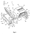
- FIG. 2 It can be seen where a drive unit 68 is arranged on a base 70 and supplies the garden couch 2 according to the invention with sufficient electricity.
- the drive unit 68 is in FIG. 3 shown in more detail.
- the drive unit 68 could, for example, have a base 70 and a cover 72, wherein an accumulator 38, an electronics unit 40 and a compressor 60 could be arranged on the floor 70.
- a number of sockets 76 could be arranged, which offer a variety of connection options.
- a Netzanschuss 78 could be present, on which a cable for operating the garden lounger 2 according to the invention is allowed from a public power grid.
- this power connector 78 could be too serve to charge the accumulator 38, wherein the electronic unit 40 also acts as a charging electronics.
- the garden lounger 2 according to the invention could be allowed to operate rapidly when the rechargeable battery 38 is heavily discharged.
- this small appliance connection 80 is shown as a USB connection, since today many mobile electronic devices can be supplied with power via such a connection.
- the electronics unit 40 simultaneously acts as a voltage converter, providing that terminal 80 with a constant voltage of 5 volts and at the same time limiting the current to 0.5 amps or another predetermined common maximum value.
- the garden lounger 2 according to the invention Since the garden lounger 2 according to the invention is used predominantly in good weather, it is recommended to arrange on the lid 72 one or more solar cells 82, which are also to be connected to the electronic unit 40. In this way it can be ensured that the garden lounger 2 according to the invention is always ready for use, because the accumulator 38 could always remain charged by the operation of the solar cells 82.
- the electronic unit 40 functions in such a structure of the drive unit 68 as a voltage converter, which converts the voltage provided by the solar cell 82 voltage into a charging voltage.
- the electronics unit 40 should continue to be able to maintain the accumulator 38 always, that is, it must be ensured that the accumulator 38 is neither overcharged nor discharged deeply.
- connection sockets can be arranged to protect against weather or salt water in a threaded housing recess, each of which allows a screw with a screw 84.
- the embodiments shown in the Figures 1-3 serve only illustration, the invention is not limited to the illustrated embodiments. This is especially true for the division of the bed frame in five lying frame zones, it is also more or less zones feasible.
- at least one pivotable backrest is to be provided in the design of such garden beds, and preferably also an adjustable foot part.
- This embodiment of the drive unit according to the invention is likewise not limited to being arranged in a receiving compartment below the foot end or being set on a base next to the foot part. Rather, the creative freedom of the skilled person no limits, but at the time of the application revealed that the positions and arrangements shown appear quite beneficial.
- the invention is not limited to using a particular type of drive devices.
- a pneumatic drive could be coupled in the form of a pneumatic cylinder with the compressor for an air mattress.
- a very variable concept of the drive is possible because only compressed air must be transferred within the garden lounger according to the invention.
Landscapes
- Health & Medical Sciences (AREA)
- General Health & Medical Sciences (AREA)
- Nursing (AREA)
- Dentistry (AREA)
- Special Chairs (AREA)
- Invalid Beds And Related Equipment (AREA)
- Charge And Discharge Circuits For Batteries Or The Like (AREA)
Priority Applications (1)
| Application Number | Priority Date | Filing Date | Title |
|---|---|---|---|
| PL10779473T PL2498646T3 (pl) | 2009-11-10 | 2010-11-10 | Elektryczna leżanka ogrodowa |
Applications Claiming Priority (2)
| Application Number | Priority Date | Filing Date | Title |
|---|---|---|---|
| DE102009052396.0A DE102009052396B4 (de) | 2009-11-10 | 2009-11-10 | Elektrische Gartenliege |
| PCT/EP2010/006840 WO2011057772A1 (de) | 2009-11-10 | 2010-11-10 | Elektrische gartenliege |
Publications (2)
| Publication Number | Publication Date |
|---|---|
| EP2498646A1 EP2498646A1 (de) | 2012-09-19 |
| EP2498646B1 true EP2498646B1 (de) | 2014-03-19 |
Family
ID=46483900
Family Applications (1)
| Application Number | Title | Priority Date | Filing Date |
|---|---|---|---|
| EP10779473.7A Active EP2498646B1 (de) | 2009-11-10 | 2010-11-10 | Elektrische gartenliege |
Country Status (6)
| Country | Link |
|---|---|
| US (1) | US9339114B2 (pl) |
| EP (1) | EP2498646B1 (pl) |
| CN (1) | CN102595975B (pl) |
| ES (1) | ES2469823T3 (pl) |
| PL (1) | PL2498646T3 (pl) |
| PT (1) | PT2498646E (pl) |
Cited By (1)
| Publication number | Priority date | Publication date | Assignee | Title |
|---|---|---|---|---|
| DE202024105131U1 (de) | 2024-09-06 | 2024-10-14 | Genima Innovations Marketing Gmbh | Solarbetriebener Liegestuhl |
Families Citing this family (18)
| Publication number | Priority date | Publication date | Assignee | Title |
|---|---|---|---|---|
| US8926008B1 (en) | 2014-08-26 | 2015-01-06 | Khaled Jafar Al-Hasan | Portable folding chair |
| DE202014007107U1 (de) | 2014-09-01 | 2014-09-24 | Martin Scharfe | Selbstfahrende Garten- oder Freizeitliege |
| US9578972B2 (en) | 2015-05-22 | 2017-02-28 | Patricia Purintun | Chair assembly |
| US10058179B2 (en) * | 2015-11-30 | 2018-08-28 | Era Nouveau, LLC | Adjustable fully upholstered chaise lounger |
| US20170164742A1 (en) * | 2015-12-10 | 2017-06-15 | Ronny Hay | Luxurious motorized poolside lounger and related system |
| CN107772902B (zh) * | 2016-08-31 | 2018-11-20 | 麒盛科技股份有限公司 | 一种应用于电动床的腰部顶出机构以及包括该腰部顶出机构的电动床 |
| US10154732B2 (en) * | 2016-12-16 | 2018-12-18 | Brendan O'Neill | Portable surface for lounging or sleeping |
| DE202017103193U1 (de) * | 2017-05-26 | 2018-08-28 | Rom Ag | Sitzmöbel |
| WO2019012982A1 (ja) * | 2017-07-14 | 2019-01-17 | シャープ株式会社 | 太陽電池を備えた椅子 |
| TWM553151U (zh) * | 2017-07-24 | 2017-12-21 | Quan Hang Shi | 電動床 |
| CN111465420B (zh) | 2017-12-15 | 2023-04-18 | 佩尔福兹有限公司 | 改进的导管和结合这种导管的装置和系统 |
| US11116320B2 (en) | 2019-01-16 | 2021-09-14 | Nilo Morales | Collapsible chair and solar panel shade charger system |
| US10925405B2 (en) * | 2019-07-11 | 2021-02-23 | Vladimir Dorsainvil | Solar charged beach chair assembly |
| US20210274937A1 (en) * | 2020-03-03 | 2021-09-09 | Keith Goldstein | Solar powered chaise lounge |
| US20260041241A1 (en) * | 2022-06-18 | 2026-02-12 | Burnis Garner | CoolChair |
| TWI803397B (zh) * | 2022-07-21 | 2023-05-21 | 施權航 | 電動床 |
| PL445089A1 (pl) * | 2023-05-31 | 2024-12-02 | Sunbed Pro Spółka Z Ograniczoną Odpowiedzialnością | Leżak, zwłaszcza do opalania |
| US20250134257A1 (en) * | 2023-10-26 | 2025-05-01 | Laura Alcorn | Rotatable suntanning chair device |
Family Cites Families (32)
| Publication number | Priority date | Publication date | Assignee | Title |
|---|---|---|---|---|
| US4188677A (en) * | 1977-11-30 | 1980-02-19 | Zur Henry C | Lounger bed and adjustable body supporting assembly |
| US4379588A (en) * | 1980-11-03 | 1983-04-12 | Speice Donald G | Revolving solar lounger |
| US4597119A (en) * | 1984-12-17 | 1986-07-01 | Edwin Padgett | Suntanning device |
| DE3611544A1 (de) | 1986-04-05 | 1987-10-08 | Remscheid Volksbank | Vorrichtung zum erzeugen von elektrischen strom durch solarzellen |
| GB8724345D0 (en) * | 1987-10-16 | 1987-11-18 | Ortlieb J F | Chair for sunbathing |
| US4856520A (en) * | 1988-03-10 | 1989-08-15 | Bilicki Donald G | Tanner's platform |
| US5159191A (en) * | 1990-11-29 | 1992-10-27 | Mankovitz Roy J | Apparatus and method for using ambient light to control electronic apparatus |
| US5211172A (en) * | 1991-03-29 | 1993-05-18 | Mcguane Joseph B | Solar controlled sun tracker for a sunbather |
| US5564784A (en) * | 1992-06-09 | 1996-10-15 | Felling; Gerald J. | Knock-down sheltering and astrological observation lounge |
| US5395157A (en) * | 1993-12-10 | 1995-03-07 | Rollo; Linda | Rotatable suntanning chair with insulated base |
| DE4404330A1 (de) | 1994-02-11 | 1994-08-25 | Cremerius Alois | Vorrichtung zur Durchführung "Physikalischer Therapie", z.B. Paraffin - Fango - Applikationen |
| AT561U1 (de) | 1995-04-19 | 1996-01-25 | Zotter Herbert | Camping- oder freizeitliege |
| US5893608A (en) * | 1997-04-28 | 1999-04-13 | Cravenor; William | Sun-tracking chair |
| US5944384A (en) * | 1997-05-24 | 1999-08-31 | Patterson; Steve | Sun following swivel beach chair |
| US6000353A (en) * | 1997-06-02 | 1999-12-14 | De Leu; Douglas F. | Solar powered raft with guidance system |
| US6217118B1 (en) * | 1997-06-16 | 2001-04-17 | Trw Occupant Restraint Systems Gmbh & Co. Kg | Car seat with displaceable head rest |
| US5897163A (en) * | 1997-08-01 | 1999-04-27 | Singer; Andrew | Suntanning apparatus |
| US5975630A (en) * | 1998-10-23 | 1999-11-02 | Schreiber; Diana M. | Sun tracking lounge chair |
| DE10126191C1 (de) * | 2001-05-30 | 2003-01-09 | Bosch Gmbh Robert | Anordnung zur drahtlosen Informations- und/oder Energieübertragung zwischen einem herausnehmbaren Fahrzeugsitz und der Fahrzeugkarosserie |
| FR2846208A1 (fr) | 2002-10-23 | 2004-04-30 | Patrice Charreau | Chaise longue |
| DE20314184U1 (de) | 2003-09-12 | 2003-11-06 | Hansa-Holz-Kontor Horst Rückle GmbH & Co. KG, 21614 Buxtehude | Liege in Form einer Gartenliege |
| KR100534956B1 (ko) * | 2003-11-05 | 2005-12-08 | 현대자동차주식회사 | 차량용 시트 가열장치 |
| DE202004011096U1 (de) | 2004-07-14 | 2005-11-24 | Cimosys Ag | Im Freien oder in Feuchträumen verwendbares Sitz- und/oder Liegemöbel, insbesondere Gartenliege o.dgl. |
| DE202004014101U1 (de) | 2004-09-08 | 2004-11-25 | Dewert Antriebs- Und Systemtechnik Gmbh & Co. Kg | Mobile Gartenartikel |
| US7931334B1 (en) * | 2004-12-07 | 2011-04-26 | Steven Jerome Caruso | Custom controlled seating surface technologies |
| US7025418B1 (en) * | 2005-07-01 | 2006-04-11 | Mike Hackal | Positionable floating chair |
| US7786622B2 (en) | 2007-03-01 | 2010-08-31 | Graco Children's Products Inc. | Juvenile product inductive power transfer |
| DE202008003844U1 (de) | 2008-03-19 | 2008-07-10 | DAHLMANN-Yave Ltd., Buji | Liege- und oder Sitzmöbel |
| US7759900B2 (en) * | 2008-04-02 | 2010-07-20 | American Power Conversion Corporation | Non-isolated charger with bi-polar inputs |
| US8091960B2 (en) * | 2008-05-01 | 2012-01-10 | Delphi Technologies, Inc. | Seat assembly having seat heating and occupant detection |
| US8203657B2 (en) * | 2008-07-11 | 2012-06-19 | Audiovox Corporation | Inductively powered mobile entertainment system |
| US8061864B2 (en) * | 2009-05-12 | 2011-11-22 | Kimball International, Inc. | Furniture with wireless power |
-
2010
- 2010-11-10 PL PL10779473T patent/PL2498646T3/pl unknown
- 2010-11-10 ES ES10779473.7T patent/ES2469823T3/es active Active
- 2010-11-10 PT PT107794737T patent/PT2498646E/pt unknown
- 2010-11-10 US US13/504,301 patent/US9339114B2/en active Active
- 2010-11-10 CN CN201080050369.3A patent/CN102595975B/zh active Active
- 2010-11-10 EP EP10779473.7A patent/EP2498646B1/de active Active
Cited By (1)
| Publication number | Priority date | Publication date | Assignee | Title |
|---|---|---|---|---|
| DE202024105131U1 (de) | 2024-09-06 | 2024-10-14 | Genima Innovations Marketing Gmbh | Solarbetriebener Liegestuhl |
Also Published As
| Publication number | Publication date |
|---|---|
| EP2498646A1 (de) | 2012-09-19 |
| PT2498646E (pt) | 2014-06-25 |
| US20120205951A1 (en) | 2012-08-16 |
| PL2498646T3 (pl) | 2014-09-30 |
| CN102595975A (zh) | 2012-07-18 |
| CN102595975B (zh) | 2017-07-07 |
| ES2469823T3 (es) | 2014-06-20 |
| HK1175967A1 (en) | 2013-07-19 |
| US9339114B2 (en) | 2016-05-17 |
Similar Documents
| Publication | Publication Date | Title |
|---|---|---|
| EP2498646A1 (de) | Elektrische gartenliege | |
| EP3506801B1 (de) | Solargespiesene elektrisch verstellbare sonnenliege | |
| WO2011057772A1 (de) | Elektrische gartenliege | |
| DE102018103067A1 (de) | Möbelsystem | |
| DE202012011438U1 (de) | Bausatz Photovoltaik-Pavillon | |
| DE202008003844U1 (de) | Liege- und oder Sitzmöbel | |
| DE102021108548A1 (de) | Mobiles Therapiemöbel mit Liege- und Sitzfunktion | |
| DE202014007107U1 (de) | Selbstfahrende Garten- oder Freizeitliege | |
| DE29501583U1 (de) | Sonnenschirm mit integrierten Solarzellen | |
| DE202007006790U1 (de) | Textile Stuhl-, Bank- oder Bodenauflage, insbesondere für den Außenbereich von Gebäuden | |
| DE202021004092U1 (de) | Verstellbares Basiselement für Liegemöbel sowie Liegemöbel | |
| EP2175758B1 (de) | Sonnenliege | |
| DE202026100326U1 (de) | Sonnenliege | |
| HK1175967B (en) | Electric outdoor lounge chair | |
| DE202010011284U1 (de) | Freiluftmöbel | |
| DE202018003515U1 (de) | Sitzkissen für Treppenstufen | |
| DE20318587U1 (de) | Vorrichtung zum Aufstellen von Liegestühlen | |
| CN206885107U (zh) | 一种园林建筑用栽树辅助装置 | |
| DE202011107969U1 (de) | Modular zusammengesetztes Sonnenschutzsystem | |
| DE202020107062U1 (de) | Kopfstützenverstellung | |
| DE102015103049A1 (de) | Strandkorb | |
| EP2005991A1 (de) | Einrichtung für das Bestrahlen eines menschlichen Körpers mit UV-Licht nebst Verfahren | |
| DE202014006294U1 (de) | Sitz- und Liegemöbelstück für Menschen mit Paraplegie | |
| DE202020000676U1 (de) | Smartes flexibles Sitzmöbel | |
| EP1325695A1 (de) | Ruhemöbel für den Aussenbereich |
Legal Events
| Date | Code | Title | Description |
|---|---|---|---|
| PUAI | Public reference made under article 153(3) epc to a published international application that has entered the european phase |
Free format text: ORIGINAL CODE: 0009012 |
|
| 17P | Request for examination filed |
Effective date: 20120510 |
|
| AK | Designated contracting states |
Kind code of ref document: A1 Designated state(s): AL AT BE BG CH CY CZ DE DK EE ES FI FR GB GR HR HU IE IS IT LI LT LU LV MC MK MT NL NO PL PT RO RS SE SI SK SM TR |
|
| DAX | Request for extension of the european patent (deleted) | ||
| 17Q | First examination report despatched |
Effective date: 20130318 |
|
| REG | Reference to a national code |
Ref country code: HK Ref legal event code: DE Ref document number: 1175967 Country of ref document: HK |
|
| REG | Reference to a national code |
Ref country code: DE Ref legal event code: R079 Ref document number: 502010006442 Country of ref document: DE Free format text: PREVIOUS MAIN CLASS: A47D0005000000 Ipc: A47C0020040000 |
|
| RIC1 | Information provided on ipc code assigned before grant |
Ipc: A47C 21/06 20060101ALI20130822BHEP Ipc: A47C 20/04 20060101AFI20130822BHEP Ipc: A47C 1/14 20060101ALI20130822BHEP |
|
| GRAP | Despatch of communication of intention to grant a patent |
Free format text: ORIGINAL CODE: EPIDOSNIGR1 |
|
| INTG | Intention to grant announced |
Effective date: 20131010 |
|
| GRAS | Grant fee paid |
Free format text: ORIGINAL CODE: EPIDOSNIGR3 |
|
| GRAA | (expected) grant |
Free format text: ORIGINAL CODE: 0009210 |
|
| AK | Designated contracting states |
Kind code of ref document: B1 Designated state(s): AL AT BE BG CH CY CZ DE DK EE ES FI FR GB GR HR HU IE IS IT LI LT LU LV MC MK MT NL NO PL PT RO RS SE SI SK SM TR |
|
| REG | Reference to a national code |
Ref country code: GB Ref legal event code: FG4D Free format text: NOT ENGLISH |
|
| REG | Reference to a national code |
Ref country code: CH Ref legal event code: EP |
|
| REG | Reference to a national code |
Ref country code: AT Ref legal event code: REF Ref document number: 657071 Country of ref document: AT Kind code of ref document: T Effective date: 20140415 |
|
| REG | Reference to a national code |
Ref country code: IE Ref legal event code: FG4D Free format text: LANGUAGE OF EP DOCUMENT: GERMAN |
|
| REG | Reference to a national code |
Ref country code: DE Ref legal event code: R096 Ref document number: 502010006442 Country of ref document: DE Effective date: 20140430 |
|
| REG | Reference to a national code |
Ref country code: RO Ref legal event code: EPE |
|
| REG | Reference to a national code |
Ref country code: ES Ref legal event code: FG2A Ref document number: 2469823 Country of ref document: ES Kind code of ref document: T3 Effective date: 20140620 |
|
| REG | Reference to a national code |
Ref country code: PT Ref legal event code: SC4A Free format text: AVAILABILITY OF NATIONAL TRANSLATION Effective date: 20140616 |
|
| PG25 | Lapsed in a contracting state [announced via postgrant information from national office to epo] |
Ref country code: LT Free format text: LAPSE BECAUSE OF FAILURE TO SUBMIT A TRANSLATION OF THE DESCRIPTION OR TO PAY THE FEE WITHIN THE PRESCRIBED TIME-LIMIT Effective date: 20140319 Ref country code: NO Free format text: LAPSE BECAUSE OF FAILURE TO SUBMIT A TRANSLATION OF THE DESCRIPTION OR TO PAY THE FEE WITHIN THE PRESCRIBED TIME-LIMIT Effective date: 20140619 |
|
| REG | Reference to a national code |
Ref country code: NL Ref legal event code: VDEP Effective date: 20140319 |
|
| REG | Reference to a national code |
Ref country code: LT Ref legal event code: MG4D |
|
| PG25 | Lapsed in a contracting state [announced via postgrant information from national office to epo] |
Ref country code: FI Free format text: LAPSE BECAUSE OF FAILURE TO SUBMIT A TRANSLATION OF THE DESCRIPTION OR TO PAY THE FEE WITHIN THE PRESCRIBED TIME-LIMIT Effective date: 20140319 Ref country code: CY Free format text: LAPSE BECAUSE OF FAILURE TO SUBMIT A TRANSLATION OF THE DESCRIPTION OR TO PAY THE FEE WITHIN THE PRESCRIBED TIME-LIMIT Effective date: 20140319 Ref country code: SE Free format text: LAPSE BECAUSE OF FAILURE TO SUBMIT A TRANSLATION OF THE DESCRIPTION OR TO PAY THE FEE WITHIN THE PRESCRIBED TIME-LIMIT Effective date: 20140319 |
|
| PG25 | Lapsed in a contracting state [announced via postgrant information from national office to epo] |
Ref country code: HR Free format text: LAPSE BECAUSE OF FAILURE TO SUBMIT A TRANSLATION OF THE DESCRIPTION OR TO PAY THE FEE WITHIN THE PRESCRIBED TIME-LIMIT Effective date: 20140319 Ref country code: RS Free format text: LAPSE BECAUSE OF FAILURE TO SUBMIT A TRANSLATION OF THE DESCRIPTION OR TO PAY THE FEE WITHIN THE PRESCRIBED TIME-LIMIT Effective date: 20140319 Ref country code: LV Free format text: LAPSE BECAUSE OF FAILURE TO SUBMIT A TRANSLATION OF THE DESCRIPTION OR TO PAY THE FEE WITHIN THE PRESCRIBED TIME-LIMIT Effective date: 20140319 |
|
| REG | Reference to a national code |
Ref country code: PL Ref legal event code: T3 |
|
| REG | Reference to a national code |
Ref country code: HK Ref legal event code: GR Ref document number: 1175967 Country of ref document: HK |
|
| PG25 | Lapsed in a contracting state [announced via postgrant information from national office to epo] |
Ref country code: NL Free format text: LAPSE BECAUSE OF FAILURE TO SUBMIT A TRANSLATION OF THE DESCRIPTION OR TO PAY THE FEE WITHIN THE PRESCRIBED TIME-LIMIT Effective date: 20140319 Ref country code: EE Free format text: LAPSE BECAUSE OF FAILURE TO SUBMIT A TRANSLATION OF THE DESCRIPTION OR TO PAY THE FEE WITHIN THE PRESCRIBED TIME-LIMIT Effective date: 20140319 Ref country code: BG Free format text: LAPSE BECAUSE OF FAILURE TO SUBMIT A TRANSLATION OF THE DESCRIPTION OR TO PAY THE FEE WITHIN THE PRESCRIBED TIME-LIMIT Effective date: 20140619 Ref country code: CZ Free format text: LAPSE BECAUSE OF FAILURE TO SUBMIT A TRANSLATION OF THE DESCRIPTION OR TO PAY THE FEE WITHIN THE PRESCRIBED TIME-LIMIT Effective date: 20140319 Ref country code: IS Free format text: LAPSE BECAUSE OF FAILURE TO SUBMIT A TRANSLATION OF THE DESCRIPTION OR TO PAY THE FEE WITHIN THE PRESCRIBED TIME-LIMIT Effective date: 20140719 |
|
| PG25 | Lapsed in a contracting state [announced via postgrant information from national office to epo] |
Ref country code: SK Free format text: LAPSE BECAUSE OF FAILURE TO SUBMIT A TRANSLATION OF THE DESCRIPTION OR TO PAY THE FEE WITHIN THE PRESCRIBED TIME-LIMIT Effective date: 20140319 |
|
| REG | Reference to a national code |
Ref country code: DE Ref legal event code: R097 Ref document number: 502010006442 Country of ref document: DE |
|
| PLBE | No opposition filed within time limit |
Free format text: ORIGINAL CODE: 0009261 |
|
| STAA | Information on the status of an ep patent application or granted ep patent |
Free format text: STATUS: NO OPPOSITION FILED WITHIN TIME LIMIT |
|
| PG25 | Lapsed in a contracting state [announced via postgrant information from national office to epo] |
Ref country code: DK Free format text: LAPSE BECAUSE OF FAILURE TO SUBMIT A TRANSLATION OF THE DESCRIPTION OR TO PAY THE FEE WITHIN THE PRESCRIBED TIME-LIMIT Effective date: 20140319 |
|
| 26N | No opposition filed |
Effective date: 20141222 |
|
| PG25 | Lapsed in a contracting state [announced via postgrant information from national office to epo] |
Ref country code: IT Free format text: LAPSE BECAUSE OF FAILURE TO SUBMIT A TRANSLATION OF THE DESCRIPTION OR TO PAY THE FEE WITHIN THE PRESCRIBED TIME-LIMIT Effective date: 20140319 |
|
| REG | Reference to a national code |
Ref country code: DE Ref legal event code: R097 Ref document number: 502010006442 Country of ref document: DE Effective date: 20141222 |
|
| PG25 | Lapsed in a contracting state [announced via postgrant information from national office to epo] |
Ref country code: LU Free format text: LAPSE BECAUSE OF FAILURE TO SUBMIT A TRANSLATION OF THE DESCRIPTION OR TO PAY THE FEE WITHIN THE PRESCRIBED TIME-LIMIT Effective date: 20141110 Ref country code: MC Free format text: LAPSE BECAUSE OF FAILURE TO SUBMIT A TRANSLATION OF THE DESCRIPTION OR TO PAY THE FEE WITHIN THE PRESCRIBED TIME-LIMIT Effective date: 20140319 Ref country code: BE Free format text: LAPSE BECAUSE OF NON-PAYMENT OF DUE FEES Effective date: 20141130 |
|
| REG | Reference to a national code |
Ref country code: CH Ref legal event code: PL |
|
| PG25 | Lapsed in a contracting state [announced via postgrant information from national office to epo] |
Ref country code: CH Free format text: LAPSE BECAUSE OF NON-PAYMENT OF DUE FEES Effective date: 20141130 Ref country code: SI Free format text: LAPSE BECAUSE OF FAILURE TO SUBMIT A TRANSLATION OF THE DESCRIPTION OR TO PAY THE FEE WITHIN THE PRESCRIBED TIME-LIMIT Effective date: 20140319 Ref country code: LI Free format text: LAPSE BECAUSE OF NON-PAYMENT OF DUE FEES Effective date: 20141130 |
|
| REG | Reference to a national code |
Ref country code: IE Ref legal event code: MM4A |
|
| PG25 | Lapsed in a contracting state [announced via postgrant information from national office to epo] |
Ref country code: IE Free format text: LAPSE BECAUSE OF NON-PAYMENT OF DUE FEES Effective date: 20141110 |
|
| REG | Reference to a national code |
Ref country code: FR Ref legal event code: PLFP Year of fee payment: 6 |
|
| PG25 | Lapsed in a contracting state [announced via postgrant information from national office to epo] |
Ref country code: SM Free format text: LAPSE BECAUSE OF FAILURE TO SUBMIT A TRANSLATION OF THE DESCRIPTION OR TO PAY THE FEE WITHIN THE PRESCRIBED TIME-LIMIT Effective date: 20140319 |
|
| PG25 | Lapsed in a contracting state [announced via postgrant information from national office to epo] |
Ref country code: GR Free format text: LAPSE BECAUSE OF FAILURE TO SUBMIT A TRANSLATION OF THE DESCRIPTION OR TO PAY THE FEE WITHIN THE PRESCRIBED TIME-LIMIT Effective date: 20140620 |
|
| PG25 | Lapsed in a contracting state [announced via postgrant information from national office to epo] |
Ref country code: MT Free format text: LAPSE BECAUSE OF FAILURE TO SUBMIT A TRANSLATION OF THE DESCRIPTION OR TO PAY THE FEE WITHIN THE PRESCRIBED TIME-LIMIT Effective date: 20140319 Ref country code: HU Free format text: LAPSE BECAUSE OF FAILURE TO SUBMIT A TRANSLATION OF THE DESCRIPTION OR TO PAY THE FEE WITHIN THE PRESCRIBED TIME-LIMIT; INVALID AB INITIO Effective date: 20101110 |
|
| REG | Reference to a national code |
Ref country code: FR Ref legal event code: PLFP Year of fee payment: 7 |
|
| REG | Reference to a national code |
Ref country code: AT Ref legal event code: MM01 Ref document number: 657071 Country of ref document: AT Kind code of ref document: T Effective date: 20151110 |
|
| PG25 | Lapsed in a contracting state [announced via postgrant information from national office to epo] |
Ref country code: AT Free format text: LAPSE BECAUSE OF NON-PAYMENT OF DUE FEES Effective date: 20151110 |
|
| REG | Reference to a national code |
Ref country code: FR Ref legal event code: PLFP Year of fee payment: 8 |
|
| PG25 | Lapsed in a contracting state [announced via postgrant information from national office to epo] |
Ref country code: MK Free format text: LAPSE BECAUSE OF FAILURE TO SUBMIT A TRANSLATION OF THE DESCRIPTION OR TO PAY THE FEE WITHIN THE PRESCRIBED TIME-LIMIT Effective date: 20140319 |
|
| PG25 | Lapsed in a contracting state [announced via postgrant information from national office to epo] |
Ref country code: AL Free format text: LAPSE BECAUSE OF FAILURE TO SUBMIT A TRANSLATION OF THE DESCRIPTION OR TO PAY THE FEE WITHIN THE PRESCRIBED TIME-LIMIT Effective date: 20140319 |
|
| PGFP | Annual fee paid to national office [announced via postgrant information from national office to epo] |
Ref country code: PT Payment date: 20251103 Year of fee payment: 16 |
|
| PGFP | Annual fee paid to national office [announced via postgrant information from national office to epo] |
Ref country code: DE Payment date: 20251126 Year of fee payment: 16 |
|
| PGFP | Annual fee paid to national office [announced via postgrant information from national office to epo] |
Ref country code: GB Payment date: 20251120 Year of fee payment: 16 |
|
| PGFP | Annual fee paid to national office [announced via postgrant information from national office to epo] |
Ref country code: FR Payment date: 20251120 Year of fee payment: 16 |
|
| PGFP | Annual fee paid to national office [announced via postgrant information from national office to epo] |
Ref country code: TR Payment date: 20251107 Year of fee payment: 16 |
|
| PGFP | Annual fee paid to national office [announced via postgrant information from national office to epo] |
Ref country code: PL Payment date: 20251104 Year of fee payment: 16 |
|
| PGFP | Annual fee paid to national office [announced via postgrant information from national office to epo] |
Ref country code: RO Payment date: 20251110 Year of fee payment: 16 |
|
| PGFP | Annual fee paid to national office [announced via postgrant information from national office to epo] |
Ref country code: ES Payment date: 20251216 Year of fee payment: 16 |