EP2497729A2 - Sheet feeder and image forming apparatus - Google Patents
Sheet feeder and image forming apparatus Download PDFInfo
- Publication number
- EP2497729A2 EP2497729A2 EP12158862A EP12158862A EP2497729A2 EP 2497729 A2 EP2497729 A2 EP 2497729A2 EP 12158862 A EP12158862 A EP 12158862A EP 12158862 A EP12158862 A EP 12158862A EP 2497729 A2 EP2497729 A2 EP 2497729A2
- Authority
- EP
- European Patent Office
- Prior art keywords
- attraction
- sheet
- separation unit
- transmitting portion
- drive transmitting
- Prior art date
- Legal status (The legal status is an assumption and is not a legal conclusion. Google has not performed a legal analysis and makes no representation as to the accuracy of the status listed.)
- Granted
Links
Images


Classifications
-
- G—PHYSICS
- G03—PHOTOGRAPHY; CINEMATOGRAPHY; ANALOGOUS TECHNIQUES USING WAVES OTHER THAN OPTICAL WAVES; ELECTROGRAPHY; HOLOGRAPHY
- G03G—ELECTROGRAPHY; ELECTROPHOTOGRAPHY; MAGNETOGRAPHY
- G03G15/00—Apparatus for electrographic processes using a charge pattern
- G03G15/65—Apparatus which relate to the handling of copy material
- G03G15/6502—Supplying of sheet copy material; Cassettes therefor
- G03G15/6511—Feeding devices for picking up or separation of copy sheets
-
- B—PERFORMING OPERATIONS; TRANSPORTING
- B65—CONVEYING; PACKING; STORING; HANDLING THIN OR FILAMENTARY MATERIAL
- B65H—HANDLING THIN OR FILAMENTARY MATERIAL, e.g. SHEETS, WEBS, CABLES
- B65H3/00—Separating articles from piles
- B65H3/18—Separating articles from piles using electrostatic force
-
- B—PERFORMING OPERATIONS; TRANSPORTING
- B65—CONVEYING; PACKING; STORING; HANDLING THIN OR FILAMENTARY MATERIAL
- B65H—HANDLING THIN OR FILAMENTARY MATERIAL, e.g. SHEETS, WEBS, CABLES
- B65H1/00—Supports or magazines for piles from which articles are to be separated
- B65H1/08—Supports or magazines for piles from which articles are to be separated with means for advancing the articles to present the articles to the separating device
- B65H1/14—Supports or magazines for piles from which articles are to be separated with means for advancing the articles to present the articles to the separating device comprising positively-acting mechanical devices
-
- B—PERFORMING OPERATIONS; TRANSPORTING
- B65—CONVEYING; PACKING; STORING; HANDLING THIN OR FILAMENTARY MATERIAL
- B65H—HANDLING THIN OR FILAMENTARY MATERIAL, e.g. SHEETS, WEBS, CABLES
- B65H3/00—Separating articles from piles
- B65H3/02—Separating articles from piles using friction forces between articles and separator
- B65H3/04—Endless-belt separators
- B65H3/047—Endless-belt separators separating from the top of a pile
-
- B—PERFORMING OPERATIONS; TRANSPORTING
- B65—CONVEYING; PACKING; STORING; HANDLING THIN OR FILAMENTARY MATERIAL
- B65H—HANDLING THIN OR FILAMENTARY MATERIAL, e.g. SHEETS, WEBS, CABLES
- B65H2403/00—Power transmission; Driving means
- B65H2403/40—Toothed gearings
- B65H2403/41—Rack-and-pinion, cogwheel in cog railway
-
- B—PERFORMING OPERATIONS; TRANSPORTING
- B65—CONVEYING; PACKING; STORING; HANDLING THIN OR FILAMENTARY MATERIAL
- B65H—HANDLING THIN OR FILAMENTARY MATERIAL, e.g. SHEETS, WEBS, CABLES
- B65H2404/00—Parts for transporting or guiding the handled material
- B65H2404/20—Belts
- B65H2404/26—Particular arrangement of belt, or belts
- B65H2404/269—Particular arrangement of belt, or belts other arrangements
- B65H2404/2693—Arrangement of belts on movable frame
-
- B—PERFORMING OPERATIONS; TRANSPORTING
- B65—CONVEYING; PACKING; STORING; HANDLING THIN OR FILAMENTARY MATERIAL
- B65H—HANDLING THIN OR FILAMENTARY MATERIAL, e.g. SHEETS, WEBS, CABLES
- B65H2801/00—Application field
- B65H2801/03—Image reproduction devices
- B65H2801/06—Office-type machines, e.g. photocopiers
Definitions
- the present invention relates to a sheet feeder and an image forming apparatus.
- an electrostatic attraction separation method of generating an electric field on an attraction belt and bringing the attraction belt into contact with a sheet to attract and separate the sheet from other sheets.
- a background sheet feeder includes an attraction separation unit that includes an attraction belt formed by a dielectric member wound around two rollers, a charger for supplying alternating charge to the attraction belt, and a holder holding the attraction belt and the charger.
- the holder rotatably supports the two rollers, and is fixed to a rotary shaft provided upstream of the rollers in the sheet feeding direction.
- One end of the rotary shaft is provided with a gear mechanism including a rack and pinion and a swing mechanism serving as a swing device for swinging the attraction separation unit.
- one of the two rollers disposed on the upstream side in the sheet feeding direction is supported by the holder to be movable in a direction perpendicular to the surface of a sheet bundle.
- the attraction belt held by the holder via the two rollers Prior to the sheet feeding operation, the attraction belt held by the holder via the two rollers is located at a position separated from the sheet bundle.
- the attraction belt is first rotated and supplied with alternating charge. After the supply of the alternating charge to the attraction belt, the rotation of the attraction belt is stopped. Then, the swing mechanism is driven to swing the attraction separation unit toward the sheet bundle. According to this action, the attraction belt is brought into contact with the uppermost sheet of the sheet bundle to attract the uppermost sheet of the sheet bundle to the attraction belt. After the attraction of the uppermost sheet of the sheet bundle to the attraction belt, the swing mechanism is driven to swing the attraction separation unit in a direction separating from the sheet bundle. According to this action, the uppermost sheet attracted to the attraction belt is lifted by the attraction belt, and is separated from the second sheet. Then, the attraction belt is driven to rotate to feed the uppermost sheet attracted thereto.
- the attraction separation unit is configured to be cantilever-supported by the rotary shaft disposed on the upstream side in the sheet feeding direction and serve as a support member.
- the downstream end of the attraction separation unit in the sheet feeding direction acts as a free end, and the attraction separation unit vibrates owing to backlash occurring in a gear meshing portion or by resilience of the attraction separation unit.
- the vibration of the attraction separation unit may cause the uppermost sheet attracted to the attraction belt to separate from the attraction belt.
- the attraction separation unit is swung at relatively high speed to increase productivity, a load due to the inertia of the attraction separation unit is increased. Therefore, it is desirable that the attraction separation unit be reduced in weight. If the attraction separation unit is reduced in weight, however, the above-described vibration becomes more pronounced.
- a rack gear is attached to the rotary shaft serving as a fulcrum of the attraction separation unit. Therefore, a portion for transmitting drive to the attraction separation unit, i.e., a meshing portion between the rack gear and a pinion gear, is located near the rotary shaft serving as the fulcrum of the attraction separation unit.
- the centroid of the attraction separation unit is located on the downstream side in the sheet feeding direction. Therefore, the distance from the gear meshing portion serving as the point of effort in the principle of the lever to the rotation shaft serving as the fulcrum is less than the distance from the centroid of the attraction separation unit serving as the point of load in the principle of the lever to the rotary shaft serving as the fulcrum.
- the torque for swinging the attraction separation unit is increased.
- the increase in the torque leads to an increase in size of a motor for operating the attraction separation unit and the sheet feeder. Further, a relatively large load is imposed on the gear meshing portion, and thus the gears of the swing device are worn away prematurely.
- a novel sheet feeder includes an attraction separation unit and a swing device.
- the attraction separation unit includes an attraction belt stretched around two tension rollers, disposed facing the upper surface of a stacked sheet bundle to attract an uppermost sheet of the sheet bundle and rotatably supported by a support member at a position upstream of the attraction belt in a sheet feeding direction.
- the swing device swings the attraction separation unit around the support member as a fulcrum to move the attraction belt back and forth between an attraction position for attracting the uppermost sheet of the sheet bundle to the attraction belt and a feed position for feeding the uppermost sheet attracted to the attraction belt further from the sheet bundle than the attraction position.
- the swing device includes an assembly of a first drive transmitting portion and a second drive transmitting portion.
- the first drive transmitting portion is attached to a downstream end portion of the attraction separation unit in the sheet feeding direction.
- the second drive transmitting portion is attached to the body of the sheet feeder and connected with the first drive transmitting portion.
- the first drive transmitting portion and the second drive transmitting portion connect with each other to swing the attraction separation unit.
- An upstream one of the two tension rollers in the sheet feeding direction may be movable in a direction perpendicular to the upper surface of the sheet bundle.
- the attraction separation unit may include a bracket configured to rotatably support the tension rollers and a downstream end portion of the bracket in the sheet feeding direction forms the first drive transmitting portion.
- One of the first drive transmitting portion and the second drive transmitting portion may form a rack, and the other one of the first drive transmitting portion and the second drive transmitting portion may form a pinion.
- the pinion may receive drive force of a drive source transmitted thereto.
- the rack may be formed into a substantially circular arc shape centering around a position upstream of the first drive transmitting portion and the second drive transmitting portion in the sheet feeding direction.
- the rack may be formed into a substantially circular arc shape centering around the fulcrum of the attraction separation unit.
- the first drive transmitting portion may form the rack, and the second drive transmitting portion may form the pinion.
- a connecting position between the first drive transmitting portion and the second drive transmitting portion may be disposed downstream of the centroid of the attraction separation unit in the sheet feeding direction.
- the connecting position between the first drive transmitting portion and the second drive transmitting portion and the centroid of the attraction separation unit located at the feed position may be at the same position in the sheet feeding direction.
- the assemblies of the first drive transmitting portion and the second drive transmitting portion may be provided to each of lateral opposite end portions of the attraction separation unit at lateral ends of the attraction belt.
- Each assembly of the first drive transmitting portion and the second drive transmitting portion provided to each of lateral opposite end portions of the attraction separation unit at lateral ends of the attraction belt may be driven by a common drive source.
- the second drive transmitting portion provided to the one of the lateral opposite end portions of the attraction separation unit in the width direction of the attraction belt and the second drive transmitting portion provided to the other one of the lateral opposite end portions of the attraction separation unit in the width direction of the attraction belt may be supported by a common rotary shaft disposed outside the range between the attraction position and the feed position of the attraction belt.
- An upstream one of the two tension rollers in the sheet feeding direction may be immovable in a direction perpendicular to the upper surface of the sheet bundle.
- a novel image forming apparatus includes an image forming device configured to form an image on a sheet and the above-described sheet feeder configured to separate an uppermost sheet from a stacked sheet bundle and feed the uppermost sheet to the image forming device.
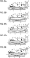
- FIG 1 is a schematic diagram illustrating a copier according to an embodiment of the present invention
- FIG 2 is a perspective view illustrating a schematic configuration of a sheet feeding unit of the copier
- FIG 3 is a schematic diagram illustrating a basic configuration of a sheet feeder provided in the sheet feeding unit
- FIGs. 4A and 4B are diagrams illustrating side and plane views, respectively, of a configuration of main components of an attraction separation unit of the sheet feeder;
- FIG 5 is a schematic plan view of a drive mechanism of the sheet feeder
- FIG 6 is a perspective view illustrating a configuration of main components of the attraction separation unit
- FIG 7 is a perspective view illustrating a modified example of the attraction separation unit
- FIGs. 8A to 8E are diagrams illustrating separation and feeding of a sheet performed by the sheet feeder
- FIG 9 is a diagram illustrating the relationship between the centroid of the attraction separation unit and a meshing position of a swing mechanism
- FIG 10 is a diagram illustrating a configuration having a rack and pinion mechanism provided only to one end of the attraction separation unit in a belt width direction;
- FIG 11 is a schematic configuration diagram of a sheet feeder according to a first modified example
- FIG 12 is a schematic configuration diagram of a drive mechanism and a swing mechanism of the sheet feeder according to the first modified example
- FIG 13 is a schematic configuration diagram of a sheet feeder according to a second modified example
- FIG 14 is a schematic configuration diagram of a swing mechanism of the sheet feeder according to the second modified example.
- FIG 15 is a schematic configuration diagram of a sheet feeder according to a third modified example.
- FIG 16 is a diagram illustrating another example of a swing mechanism of the sheet feeder according to the third modified example.
- FIG 1 is a schematic diagram illustrating a copier 100 according to the present embodiment.
- the copier 100 includes an automatic document feeder 59, a document reading unit 58, and an image forming unit 50.
- the automatic document feeder 59 separates a document from a document bundle loaded on a document tray 59a, and automatically feeds the document onto a contact glass on the document reading unit 58.
- the document reading unit 58 reads the document fed onto the contact glass by the automatic document feeder 59.
- the image forming unit 50 serves as an image forming device that forms an image on a recording medium sheet (hereinafter referred to as sheet) fed from a sheet feeding unit 52 on the basis of the document image read by the document reading unit 58.
- sheet recording medium sheet
- the sheet feeding unit 52 stores a sheet bundle 1 including a plurality of stacked sheets, and feeds from the sheet bundle 1 an uppermost sheet 1a at the uppermost position thereof to the image forming unit 50.
- the image forming unit 50 and the sheet feeding unit 52 are separable from each other.
- the image forming unit 50 includes a photoconductor 61 serving as a latent image carrying member and surrounded by a charging device 62, a development device 64, a transfer device 54, a photoconductor cleaning device 65, and so forth.
- the image forming unit 50 further includes a not-illustrated optical writing unit for applying laser light 63 to the photoconductor 61 and a fixing device 55 for fixing a toner image on a sheet.
- the outer circumferential surface of the photoconductor 61 is first uniformly charged by the charging device 62 in accordance with the rotation of the photoconductor 61. Then, the photoconductor 61 is applied with the laser light 63 by the not-illustrated optical writing unit on the basis of image data input from, for example, a personal computer or a word processor or image data of the document read by the document reading unit 58. According to this action, an electrostatic latent image is formed on the photoconductor 61. Thereafter, toner supplied by the development device 64 adheres to and visualizes the electrostatic latent image. According to this action, a toner image is formed on the photoconductor 61.
- the sheet feeding unit 52 feeds each sheet by separating the sheet from the other sheets, and causes the sheet to come into contact with registration rollers 53 to be stopped.
- the sheet brought into contact with and stopped by the registration rollers 53 is then fed to a transfer unit, in which the photoconductor 61 and the transfer device 54 face each other, in proper timing with the formation of the toner image in the image forming unit 50.
- the transfer unit the toner image on the photoconductor 61 is transferred onto the supplied sheet.
- the sheet having the toner image transferred thereto is subjected to a toner image fixing process by the fixing device 55, and then is discharged to a sheet discharge tray 57 by a sheet discharging roller pair 56.
- FIG 1 also illustrates a feed roller pair 9, a sheet feeder 200, and a second sheet 1b of the sheet bundle 1, which will be described later.
- FIG 2 is a perspective view illustrating a schematic configuration of the sheet feeding unit 52.
- FIG 3 is a schematic diagram illustrating the sheet feeder 200.
- FIGs. 4A and 4B are diagrams illustrating a configuration of main components of an attraction separation unit 110 of the sheet feeder 200.
- the sheet feeding unit 52 includes a sheet feeding cassette 11 and the sheet feeder 200.
- the sheet feeding cassette 11 serves as a sheet material storing unit for storing a plurality of stacked sheets.
- the sheet feeder 200 separates and feeds, from the sheet bundle 1 including a plurality of sheets placed on the sheet feeding cassette 11, the uppermost sheet 1a at the uppermost position of the sheet bundle 1.
- the sheet feeding cassette 11 includes a bottom plate 7 for carrying the sheet bundle 1 of a plurality of stacked sheets loaded thereon. Support members 8 for supporting the bottom plate 7 are rotatably attached between the bottom plate 7 and a bottom portion of the sheet feeding cassette 11.
- the sheet feeding unit 52 is provided with a sheet detection device 40 that detects the arrival of the uppermost sheet 1a of the sheet bundle 1 to a predetermined position.
- the sheet detection device 40 includes a transmissive optical sensor 43 including a light receiving portion 43a and a light emitting portion 43b and a feeler 44 rotatably supported by a shaft 42 provided to the body of the sheet feeder 200.
- the support members 8 are rotated by a not-illustrated drive motor to lift the bottom plate 7, the sheet bundle 1 loaded on the bottom plate 7 is lifted, and the uppermost sheet 1a comes into contact with the feeler 44.
- the light receiving portion 43a receives the light emitted from the light emitting portion 43b in the transmissive optical sensor 43.
- the feeler 44 blocks the light from the light emitting portion 43b, and prevents the light receiving portion 43a from receiving the light. According to this action, the arrival of the uppermost sheet 1a of the sheet bundle 1 to the predetermined position is detected, and the rotation of the support members 8 is stopped.
- the sheet feeder 200 includes an attraction separation unit 110, a swing mechanism 120 serving as a swing device that swings the attraction separation unit 110, and a drive mechanism 130 that circularly moves an attraction belt 2 of the attraction separation unit 110.
- the attraction separation unit 110 includes the attraction belt 2 stretched between a downstream tension roller 5 and an upstream tension roller 6.
- the attraction belt 2 has a two-layer structure including an outer layer and a conductive layer.
- the outer layer is made of polyethylene terephthalate having a resistance of approximately 10 8 ⁇ cm (ohm centimeters) or more and a thickness of approximately 50 ⁇ m.
- the conductive layer has a resistance of approximately 10 6 ⁇ cm or less, and is formed by aluminum vapor deposition.
- the above-described two-layer structure of the attraction belt 2 allows the conductive layer to be used as a grounded opposite electrode.
- an electrode member 3 connected to a charging power supply 4 in FIG. 3 and serving as a charging device that supplies charge to the attraction belt 2 is allowed to be provided at any position in contact with the outer layer of the attraction belt 2.
- the inner surfaces of the opposite end edges of the attraction belt 2 are provided with ribs 23 for preventing meandering of the attraction belt 2.
- the ribs 23 engage with the opposite end surfaces of the downstream and upstream tension rollers 5 and 6 to prevent the attraction belt 2 from meandering.
- the downstream tension roller 5 has an outer circumferential surface provided with a conductive rubber layer having a resistance value of approximately 10 6 ⁇ cm.
- the upstream tension roller 6 is a metal roller.
- the downstream tension roller 5 and the upstream tension roller 6 are both grounded.
- the downstream tension roller 5 has a relatively small diameter suitable for separating a sheet from the attraction belt 2 in accordance with the curvature thereof. That is, the diameter of the downstream tension roller 5 is set to a relatively small value to increase the curvature. According to this action, the sheet attracted to and fed by the attraction belt 2 separates from the downstream tension roller 5 and enters a feed path H (see FIG. 3 ) formed by guide members 10 disposed on the downstream side in the sheet feeding direction.
- a shaft 5a of the downstream tension roller 5 is rotatably supported by a housing 20.
- a shaft 6a of the upstream tension roller 6 is rotatably supported by shaft bearings 22 held to be slidable in the sheet feeding direction relative to the housing 20.
- the shaft bearings 22 are biased by respective springs 21 toward the upstream side in the sheet feeding direction. According to this action, the upstream tension roller 6 is biased toward the upstream side in the sheet feeding direction, and applies tension to the attraction belt 2.
- the opposite end portions of the attraction separation unit 110 in the width direction of the attraction belt 2 are respectively provided with brackets 12 for swingably holding the attraction belt 2.
- the brackets 12 are rotatably supported by a support shaft 14 provided upstream of the upstream tension roller 6 in the sheet feeding direction.
- the attraction separation unit 110 is swung by the later-described swing mechanism 120 around the support shaft 14 as a fulcrum between an attraction position for attracting the uppermost sheet 1a of the sheet bundle 1 to the attraction belt 2 and a feed position for feeding the uppermost sheet 1a attracted to the attraction belt 2.
- the brackets 12 are respectively provided with slits 12a, and the shaft 6a of the upstream tension roller 6 passes through the slits 12a. According to this action, the upstream tension roller 6 is held to be movable relative to the brackets 12. By contrast, the shaft 5a of the downstream tension roller 5 passes through respective not-illustrated slits provided in the brackets 12. According to this action, the downstream tension roller 5 is held to be immovable relative to the brackets 12. As illustrated in FIG 3 , when the attraction separation unit 110 is located at the feed position, the shaft 6a of the upstream tension roller 6 is in contact with respective lower ends 41 of the slits 12a.
- Each of the slits 12a provided in the brackets 12 is formed into a substantially circular arc shape centering around the rotation center of the downstream tension roller 5 to prevent a change in the distance between the rotation center of the upstream tension roller 6 and the rotation center of the downstream tension roller 5 regardless of the movement of the shaft 6a of the upstream tension roller 6 within the slits 12a. Consequently, the tension of the attraction belt 2 is unchanged by the movement of the shaft 6a of the upstream tension roller 6 within the slits 12a.
- FIG. 5 is a schematic configuration diagram of the drive mechanism 130 that drives the attraction belt 2 to rotate.
- the support shaft 14 rotatably supporting the brackets 12 has one end fixed with a first driven pulley 26a and a second drive pulley 26b.
- the downstream tension roller 5 has one end fixed with a second driven pulley 25.
- a driven timing belt 28 is wound around the first driven pulley 26a and the second driven pulley 25.
- a drive motor 24 is provided upstream of the support shaft 14 in the sheet feeding direction.
- the drive motor 24 has a motor shaft fixed with a first drive pulley 27.
- a drive timing belt 29 is wound around the first drive pulley 27 and the second drive pulley 26b.
- the downstream tension roller 5 is driven to rotate via the drive timing belt 29 and the driven timing belt 28.
- the attraction belt 2 is driven to rotate, and the upstream tension roller 6 is rotated in accordance with the rotation of the attraction belt 2 owing to the friction of the inner circumferential surface of the attraction belt 2.
- the drive force of the drive motor 24 is transmitted to the downstream tension roller 5 via the support shaft 14 supporting the brackets 12.
- the attraction separation unit 110 swings around the support shaft 14 as a fulcrum, as described later, and thus the distance between the downstream tension roller 5 and the support shaft 14 is unchanged by the swing of the attraction separation unit 110. Accordingly, the tension of the driven timing belt 28 is maintained, and the drive force is favorably transmitted to the downstream tension roller 5.
- the swing mechanism 120 serving as the swing device that swings the brackets 12 is provided on the downstream side in the sheet feeding direction.
- the swing mechanism 120 includes rack gear portions 13 and pinion gears 15.
- Each of the rack gear portions 13 formed in a downstream end portion of the corresponding bracket 12 in the sheet feeding direction serves as a first drive transmitting portion.
- Each of the pinion gears 15 fixed to a rotary shaft 16 and meshing with the corresponding rack gear portion 13 serves as a second drive transmitting portion.
- the swing mechanism 120 further includes a swing motor 30.
- the rotary shaft 16 has one end provided with a driven gear 32 meshing with a motor gear 31 fixed to a motor shaft of the swing motor 30.
- the pinion gears 15 With the swing motor 30 rotating the rotary shaft 16 fixed with the pinion gears 15, the pinion gears 15 are rotated. According to this action, the pinion gears 15 provided to the opposite end portions of the attraction separation unit 110 in the belt width direction are driven to rotate by the single swing motor 30. Consequently, the number of components is reduced, and thus the cost of the sheet feeder 200 is reduced. Further, the respective rack and pinions provided to the opposite end portions of the attraction separation unit 110 in the belt width direction are driven in synchronization by a relatively simple configuration.
- the rack gear portions 13 have a substantially circular arc shape centering around the support shaft 14.
- the rack gear portions 13 formed in the brackets 12 swing around the support shaft 14.
- the meshing between the rack gear portions 13 and the pinion gears 15 is maintained during the swing of the attraction separation unit 110.
- the rack gear portions 13 formed in the downstream end portions of the brackets 12 in the sheet feeding direction the number of components is reduced and the configuration is simplified, as compared with a case where rack gears formed separately from the brackets 12 are attached to the brackets 12.
- the pinions i.e., pinion gears 15
- the configuration for transmitting the drive to the pinions is simplified, as compared with a case where the pinions are provided to the attraction separation unit 110.
- the brackets 12 are connected and fixed by a reinforcing member 70. With the brackets 12 connected and fixed by the reinforcing member 70, the two brackets 12 are integrally swung. This configuration therefore suppresses twisting of the attraction belt 2 held by the brackets 12 during the swing of the brackets 12, and suppresses separation from the attraction belt 2 of the uppermost sheet 1a attracted thereto.
- the blade-like electrode member 3 serving as a charging device that charges the outer circumferential surface of the attraction belt 2 is in contact with the surface of the attraction belt 2.
- the electrode member 3 is connected to the charging power supply 4 that generates an alternating-current (hereinafter referred to as AC) voltage.
- AC alternating-current
- the electrode member 3 formed into a blade shape, it is relatively easy to reduce the pitch of alternating charging intervals, and stable charging is performed even if the attraction belt 2 has minute undulations.
- a roller-like electrode member 103 as illustrated in FIG 7 may also be used as the charging device.
- FIGs. 8A to 8E A sheet feeding operation using the sheet feeder 200 of the present embodiment will now be described with reference to FIGs. 8A to 8E .
- the bottom plate 7 is located at a lowered position, and the attraction separation unit 110 is located at the attraction position, as illustrated in FIG 8A .
- the swing motor 30 is first driven to drive the pinion gears 15 to rotate in the clockwise direction in the drawing.
- the attraction separation unit 110 is swung around the support shaft 14 as a fulcrum in the counterclockwise direction in the drawing, i.e., the direction separating from the sheet bundle 1. Then, when the attraction separation unit 110 is swung to the feed position, the driving of the swing motor 30 is stopped.
- the drive motor 24 is driven to circularly move the attraction belt 2, as illustrated in FIG 8B .
- an alternating voltage is applied to the circularly moving attraction belt 2 by the charging power supply 4 via the electrode member 3.
- charge patterns alternating with a pitch dictated by the frequency of the charging power supply 4 generating the AC voltage and the rotation speed of the attraction belt 2 are formed on the surface of the attraction belt 2.
- the pitch is set to approximately 5 mm to approximately 15 mm.
- a direct-current (hereinafter referred to as DC) voltage alternated between high and low potentials may be provided by the charging power supply 4.
- the waveform of the voltage may be, for example, a rectangular or sine wave.
- the surface of the attraction belt 2 is supplied with a rectangular-wave voltage having an amplitude of approximately 4 kV (kilovolts).
- the rotation of the attraction belt 2 is stopped, and the bottom plate 7 standing by at the lowered position starts being lifted, as illustrated in FIG 8C .
- the swing motor 30 is rotated in the reverse direction to rotate the pinion gears 15 in the counterclockwise direction in the drawing.
- the attraction separation unit 110 is swung around the support shaft 14 as a fulcrum in the clockwise direction in the drawing, i.e., a direction approaching the sheet bundle 1.
- the attraction separation unit 110 is swung around the support shaft 14 as a fulcrum in the clockwise direction in the drawing, i.e., a direction approaching the sheet bundle 1.
- the uppermost sheet 1a of the sheet bundle 1 comes into contact with the upstream tension roller 6 via the attraction belt 2.
- the upstream tension roller 6 is pushed upward by the sheet bundle 1. According to this action, the shaft 6a of the upstream tension roller 6 in contact with the lower ends 41 of the slits 12a is moved upward while being guided by the slits 12a. Further, the feeler 44 is rotated in the counterclockwise direction in the drawing in accordance with the lifting of the bottom plate 7. Then, upon arrival of the uppermost sheet 1a of the sheet bundle 1 to a predetermined position, the feeler 44 blocks the light from the light emitting portion 43b of the transmissive optical sensor 43.
- the sheet detection device 40 detects the arrival of the uppermost sheet 1a of the sheet bundle 1 to the predetermined position, and the lifting of the bottom plate 7 is stopped. Further, the rotation of the swing motor 30 is stopped upon arrival of the attraction separation unit 110 to the attraction position. If the swing motor 30 is a stepper motor, the swing motor 30 is controlled on the basis of the angle of rotation corresponding to the number of pulses, thereby stopping the attraction separation unit 110 accurately at the attraction position. If the swing motor 30 is a DC motor, the swing motor 30 is controlled on the basis of the drive time, thereby stopping the attraction separation unit 110 accurately at the attraction position.
- the attraction separation unit 110 stands by for a predetermined time in the state illustrated in FIG 8D to attract the uppermost sheet 1a to the attraction belt 2. Then, the swing motor 30 is driven to drive the pinion gears 15 to rotate in the clockwise direction in the drawing, and the attraction separation unit 110 is swung around the support shaft 14 as a fulcrum in the counterclockwise direction in the drawing. According to this action, the downstream tension roller 5 moves together with the brackets 12 in the direction separating from the sheet bundle 1. By contrast, the weight of the upstream tension roller 6 keeps the upstream tension roller 6 pressed against the upper surface of the sheet bundle 1, and relatively moves toward the sheet bundle 1 relative to the brackets 12.
- the attraction belt 2 makes a swinging motion around the rotation center of the upstream tension roller 6, and the uppermost sheet 1a attracted to the attraction belt 2 is bent at a portion of the attraction belt 2 wound around the upstream tension roller 6 as a fulcrum.
- resilience acts on the uppermost sheet 1a attracted to the attraction belt 2.
- only the uppermost sheet 1a is attracted to the attraction belt 2, and the second sheet 1b is separated from the uppermost sheet 1a owing to the resilience of the uppermost sheet 1a.
- the shaft 6a of the upstream tension roller 6 comes into contact with the lower ends 41 of the slits 12a. If the attraction separation unit 110 is further rotated in a state in which the shaft 6a of the upstream tension roller 6 is thus in contact with the lower ends 41 of the slits 12a, the upstream tension roller 6 moves together with the brackets 12 and separates from the upper surface of the sheet bundle 1. As illustrated in FIG 8E , once the attraction separation unit 110 reaches the feed position for feeding a sheet, the driving of the swing motor 30 is stopped.
- the drive motor 24 is driven to circularly move the attraction belt 2 and feed the uppermost sheet 1a attracted to the attraction belt 2 toward the feed roller pair 9.
- the drive motor 24 is driven to circularly move the attraction belt 2 and feed the uppermost sheet 1a attracted to the attraction belt 2 toward the feed roller pair 9.
- the feed roller pair 9 and the attraction belt 2 are set to rotate at the same linear velocity. If the feed roller pair 9 is intermittently driven to adjust the feed timing, the drive motor 24 is controlled to also intermittently drive the attraction belt 2. Further, the drive mechanism 130 may be provided with an electromagnetic clutch to control the driving of the attraction belt 2.
- the attraction belt 2 may be charged only by the length from the sheet separation position of the attraction belt 2 to the feed roller pair 9 and thereafter be discharged by the electrode member 3. This configuration allows the uppermost sheet 1a fed to the feed roller pair 9 to be thereafter fed solely by the feeding force of the feed roller pair 9 unaffected by the attraction belt 2. Further, the discharging of the attraction belt 2 suppresses electrostatic attraction of the second sheet 1b to the attraction belt 2, from which the second sheet 1b is separated.
- the brackets 12 are provided with the respective slits 12a, and the shaft 6a of the upstream tension roller 6 engages the slits 12a.
- any other configuration may be employed which holds the upstream tension roller 6 to be swingable around the downstream tension roller 5 relative to the brackets 12, and which supports the upstream tension roller 6 such that the attraction belt 2 has a predetermined angle of tilt relative to the upper surface of the sheet bundle 1 when the attraction separation unit 110 is located at the feed position.
- the uppermost sheet 1a is electrostatically attracted to the attraction belt 2 to be separated from the second sheet 1b. Therefore, multiple sheet feeding (i.e., feeding of a plurality of sheets in an overlapped manner) due to the influence of the coefficient of friction of sheets does not occur, unlike the configuration according to the separation method using frictional force.
- gear meshing between the pinion gears 15 and the rack gear portions 13 causes the attraction separation unit 110 to swing. Therefore, the swing from the attraction position to the feed position and the swing from the feed position to the attraction position are both performed by the drive force of the swing motor 30. Thus, the attraction separation unit 110 is lowered to the attraction position faster than the speed of free fall thereof. After the feeding of the first sheet, therefore, the operation of attracting the next sheet is promptly started, and a reduction in the interval between the sheets is attained. Consequently, productivity is increased.
- the swing mechanism 120 is provided on the downstream side in the sheet feeding direction at a position relatively distant from the support shaft 14 serving as the fulcrum of the attraction separation unit 110. According to this action, the downstream side of the attraction separation unit 110 in the sheet feeding direction is supported by the pinion gears 15 and the rack gear portions 13 meshing with each other. As a result, the opposite end portions of the attraction separation unit 110 are respectively supported by the support shaft 14 and the swing mechanism 120, and the vibration of the attraction separation unit 110 is minimized, as compared with a case where only one end of the attraction separation unit 110 is supported. This configuration suppresses the separation from the attraction belt 2 of the uppermost sheet 1a attracted thereto due to the vibration of the attraction separation unit 110.
- the drive force is transmitted to the attraction separation unit 110 to swing the attraction separation unit 110.
- the portion for transmitting the drive force is thus set to a position relatively distant from the support shaft 14. According to the principle of the lever, therefore, the attraction separation unit 110 is swung with a relatively small load, as compared with a case where the drive force is transmitted on the side of the support shaft 14, i.e., the upstream side of the attraction separation unit 110 in the sheet feeding direction. Accordingly, an increase in size of the swing motor 30 is prevented, and thus an increase in size of the sheet feeder 200 is minimized. Further, abrasion of the meshing portions between the pinion gears 15 and the rack gear portions 13 is minimized.
- a meshing position K between the pinion gears 15 and the rack gear portions 13 is set to be downstream of a centroid P of the attraction separation unit 110 in the sheet feeding direction, as illustrated in FIG 9 . If the meshing position K is located upstream of the centroid P of the attraction separation unit 110 in the sheet feeding direction, the centroid P of the attraction separation unit 110 is located near a free end of the attraction separation unit 110 not supported by the support shaft 14 and the meshing portions of the swing mechanism 120, i.e., located downstream of the meshing position K in the sheet feeding direction.
- the meshing position K is set to be downstream of the centroid P of the attraction separation unit 110 in the sheet feeding direction, as in the present embodiment, the elastic vibration occurs in the attraction separation unit 110, which is supported at the opposite end portions thereof. Accordingly, the amplitude of the vibration is reduced, and the time taken for attenuation of the vibration is reduced.
- the position of the attraction separation unit 110 is retained by the pinion gears 15 and the rack gear portions 13 meshing with each other. If the swing motor 30 is accurately controlled, therefore, the position of the attraction separation unit 110 is accurately controlled. Accordingly, the attraction separation unit 110 is accurately set to the feed position.
- the swing mechanism 120 is provided on the downstream side in the sheet feeding direction at a position relatively distant from the support shaft 14 serving as the fulcrum. Therefore, the amount of movement per pitch of the attraction separation unit 110 is less than in a case where the swing mechanism 120 is provided on the side of the support shaft 14, i.e., the upstream side in the sheet feeding direction. Thus, the position of the attraction separation unit 110 is controlled with higher accuracy.
- the attraction separation unit 110 is accurately set to the intended feed position, and the uppermost sheet 1a is smoothly fed to the feed roller pair 9. Accordingly, the leading end of the uppermost sheet 1a is prevented from bumping against the feed roller pair 9 and causing vibration resulting in separation of the uppermost sheet 1a from the attraction belt 2.
- the rack and pinion mechanism may be provided only to one of the opposite end portions of the attraction separation unit 110 in the belt width direction.
- FIG 11 is a schematic configuration diagram illustrating a sheet feeder 200A according to the first modified example.
- FIG 12 is a schematic configuration diagram illustrating the drive mechanism 130 and the swing mechanism 120 of the sheet feeder 200A according to the first modified example. The illustration of the attraction belt 2 and so forth is omitted in FIG 12 .
- a rack and pinion of the swing mechanism 120 includes a pinion gear 45 provided to one of the brackets 12 and a rack gear 46 provided to the body of the sheet feeder 200A.
- the pinion gear 45 is rotatably supported by the shaft 5a of the downstream tension roller 5.
- the pinion gear 45 is provided with a pulley portion 45a, and a first timing belt 48 is wound around the pulley portion 45a and a driven pulley 47 provided to the support shaft 14. Further, a second timing belt 49 is wound around the driven pulley 47 and a drive pulley 310 provided to the motor shaft of the swing motor 30.
- the drive force of the swing motor 30 is transmitted to the pinion gear 45 via the support shaft 14.
- the drive force of the swing motor 30 is favorably transmitted to the pinion gear 45, with the first timing belt 48 not sagging owing to the swing of the attraction separation unit 110.
- the configuration having the pinion gear 45 provided to the attraction separation unit 110, as in the first modified example, is advantageous in a case where the amount of swing of the attraction separation unit 110 is relatively large. That is, while a rack gear is desired to be increased in size in accordance with the amount of swing of the attraction separation unit 110, a pinion gear may be set to a fixed size regardless of the amount of swing of the attraction separation unit 110. Therefore, an increase in size of the attraction separation unit 110 is prevented, and an increase in the load during the swing of the attraction separation unit 110 due to an increase in weight thereof is minimized. If the amount of swing is relatively large, therefore, the configuration of the first modified example may be employed to increase the swing speed of the attraction separation unit 110 and thereby increase productivity.
- FIG 13 is a schematic configuration diagram of a sheet feeder 200B according to the second modified example.
- FIG 14 is a schematic configuration diagram of the swing mechanism 120 of the sheet feeder 200B according to the second modified example.
- the position of the centroid P of the attraction separation unit 110 located at the feed position and the meshing position K between the rack gear portion 13 and the pinion gear 15 of the swing mechanism 120 are set to the same position in the sheet feeding direction.
- the downstream end portion of one of the brackets 12 in the sheet feeding direction is provided with a step portion provided with the rack gear portion 13 as illustrated in FIG 14 .
- the attraction separation unit 110 When the attraction separation unit 110 is stopped at the feed position, elastic vibration occurs in the attraction separation unit 110 owing to the inertia thereof. Particularly when the attraction separation unit 110 is swung at relatively high speed to increase productivity, the elastic vibration tends to be increased by the increased influence of the inertia of the attraction separation unit 110.
- the elastic vibration of the attraction separation unit 110 at the feed position may cause the uppermost sheet 1a attracted to the attraction belt 2 to separate from the attraction belt 2.
- the second modified example is configured such that the position of the centroid P of the attraction separation unit 110 located at the feed position and the meshing position K between the rack gear portion 13 and the pinion gear 15 of the swing mechanism 120 are set to the same position in the sheet feeding direction. According to this action, the elastic vibration occurring when the attraction separation unit 110 is stopped at the feed position is highly effectively minimized, and the separation of the uppermost sheet 1a from the attraction belt 2 is minimized.
- FIG 15 is a schematic configuration diagram of a sheet feeder 200C according to the third modified example.
- the upstream tension roller 6 is configured to be immovable relative to the brackets 12, and the feed position of the attraction separation unit 110 is changed in accordance with conditions such as the sheet thickness.
- the angle of tilt of the attraction belt 2 formed relative to the sheet bundle 1 in the feeding process is fixed.
- the uppermost sheet 1a may separate from the attraction belt 2.
- the third modified example supports the upstream tension roller 6 to be immovable relative to the brackets 12, and changes the range of swing of the attraction separation unit 110 in accordance with conditions, such as the sheet thickness, to change the feed position of the attraction separation unit 110.
- the rotary shaft 16 for fixing the pinion gears 15 is located in the range of swing of the attraction separation unit 110 corresponding to the encircled area indicated by a double-headed arrow in FIG 15 , the rotary shaft 16 may obstruct the feeding operation, depending on the feed position. In this case, therefore, it is desired to provide the rotary shaft 16 outside the range of swing of the attraction separation unit 110, as illustrated in FIG 15 .
- the swing motor 30 may be provided to each of the opposite end portions of the attraction separation unit 110 in the belt width direction. In this configuration, the swing mechanism 120 does not obstruct the feeding operation.
- the sheet feeder 200 includes the attraction separation unit 110 including the attraction belt 2 that is disposed to face the upper surface of the stacked sheet bundle 1 to attract the uppermost sheet 1a of the sheet bundle 1.
- the attraction separation unit 110 is rotatably supported at a position upstream of the attraction belt 2 in the sheet feeding direction.
- the sheet feeder 200 further includes the swing mechanism 120 serving as the swing device that swings the attraction separation unit 110 around the upstream position in the sheet feeding direction as a fulcrum to move the attraction belt 2 back and forth between the attraction position for attracting the uppermost sheet 1a of the sheet bundle 1 and the feed position for feeding the uppermost sheet 1a, which is more distant from the sheet bundle 1 than the attraction position is.
- the swing mechanism 120 includes at least one first drive transmitting portion attached to the downstream end portion of the attraction separation unit 110 in the sheet feeding direction and one second drive transmitting portion attached to the body of the sheet feeder 200 and meshing with the first drive transmitting portion.
- the first drive transmitting portion and the second drive transmitting portion mesh with each other to swing the attraction separation unit 110.
- this configuration allows both ends of the attraction separation unit 110 to be supported during the swing of the attraction separation unit 110, and suppresses the vibration of the attraction separation unit 110.
- the configuration allows the meshing position between the first drive transmitting portion and the second drive transmitting portion to be set to a position relatively distant from the fulcrum of the attraction separation unit 110.
- the load on the swing mechanism 120 is reduced. Accordingly, an increase in size of the swing motor 30 is prevented, and the abrasion of the meshing portion between the first drive transmitting portion and the second drive transmitting portion is minimized.
- the attraction belt 2 is stretched between two tension rollers.
- the two tension rollers include the upstream tension roller 6 located on the upstream side in the sheet feeding direction and supported to be movable in a direction perpendicular to the upper surface of the sheet bundle 1 in a predetermined range. According to this action, the sheet separation using the resilience of sheets is performed, and favorable separation performance is obtained. Further, the attraction belt 2 is separated from the upper surface of the sheet bundle 1 simply by the swing of the attraction separation unit 110.
- the attraction separation unit 110 includes at least one bracket 12 rotatably supporting the downstream and upstream tension rollers 5 and 6 and having a downstream end portion in the sheet feeding direction formed with the first drive transmitting portion.
- This configuration reduces the number of components and the cost of the sheet feeder 200, as compared with a case where the bracket 12 and the first drive transmitting portion are formed as separate members.
- the configuration further reduces the weight of the attraction separation unit 110 and the load imposed during the swing of the attraction separation unit 110. Further, the configuration reduces the inertia of the attraction separation unit 110, and thus suppresses the elastic vibration occurring when the attraction separation unit 110 is stopped at the feed position.
- the present embodiment is configured such that one of the first drive transmitting portion and the second drive transmitting portion forms a rack and the other one of the first drive transmitting portion and the second drive transmitting portion forms a pinion, and that the drive force of the swing motor 30 serving as a drive source is transmitted to the pinion.
- This configuration makes it relatively easy to provide a configuration that swings the attraction separation unit 110 in accordance with the meshing between the first drive transmitting portion and the second drive transmitting portion.
- the rack is formed into a substantially circular arc shape centering around a position upstream of the first drive transmitting portion and the second drive transmitting portion in the sheet feeding direction. According to this action, disengagement of the mutually meshing first and second drive transmitting portions is minimized during the swing of the attraction separation unit 110. Specifically, with the rack formed into a substantially circular arc shape centering around the fulcrum of the attraction separation unit 110, the disengagement of the mutually meshing first and second drive transmitting portions is prevented during the swing of the attraction separation unit 110.
- first drive transmitting portion and the second drive transmitting portion form the rack and the pinion, respectively, the mechanism for transmitting the drive to the pinion is simplified.
- the elastic vibration occurs in the attraction separation unit 110, which is supported at the opposite end portions thereof. Accordingly, the amplitude of the vibration is reduced, and the time taken for attenuation of the vibration is reduced. This configuration therefore suppresses the separation from the attraction belt 2 of the uppermost sheet 1a attracted thereto due to the vibration of the attraction separation unit 110.
- first drive transmitting portion and the second drive transmitting portion are provided to each of the opposite end portions of the attraction separation unit 110 in the belt width direction, the opposite end portions of the downstream end portion of the attraction separation unit 110 in the belt width direction are supported by the first drive transmitting portion and the second drive transmitting portion meshing with each other, and thus twisting of the attraction separation unit 110 is minimized.
- This configuration therefore suppresses the separation of the uppermost sheet 1a from the attraction belt 2 due to twisting of the attraction belt 2 resulting from the twisting of the attraction separation unit 110.
- the first and second drive transmitting portions provided to one of the opposite end portions of the attraction separation unit 110 in the belt width direction and the first and second drive transmitting portions provided to the other one of the opposite end portions of the attraction separation unit 110 in the belt width direction are supplied with the drive force from the common drive source.
- This configuration reduces the number of components and the cost of the sheet feeder 200, as compared with a case where the drive force is supplied by different drive sources on the one end portion and the other end portion of the attraction separation unit 110.
- the second drive transmitting portion provided to the one of the opposite end portions of the attraction separation unit 110 in the belt width direction and the second drive transmitting portion provided to the other one of the opposite end portions of the attraction separation unit 110 in the belt width direction are supported by the common rotary shaft 16 disposed outside the range between the attraction position and the feed position. This configuration prevents the rotary shaft 16 from obstructing the feeding operation.
- the image forming apparatus uses the above-described sheet feeder 200. Accordingly, productivity is increased, and a sheet feeding failure, such as multiple sheet feeding, is minimized.
Abstract
Description
- The present invention relates to a sheet feeder and an image forming apparatus.
- As a method of separating and feeding stacked sheets, such as documents and recording sheets, there is an electrostatic attraction separation method of generating an electric field on an attraction belt and bringing the attraction belt into contact with a sheet to attract and separate the sheet from other sheets.
- A background sheet feeder according to the electrostatic attraction separation method includes an attraction separation unit that includes an attraction belt formed by a dielectric member wound around two rollers, a charger for supplying alternating charge to the attraction belt, and a holder holding the attraction belt and the charger. The holder rotatably supports the two rollers, and is fixed to a rotary shaft provided upstream of the rollers in the sheet feeding direction. One end of the rotary shaft is provided with a gear mechanism including a rack and pinion and a swing mechanism serving as a swing device for swinging the attraction separation unit. Further, one of the two rollers disposed on the upstream side in the sheet feeding direction is supported by the holder to be movable in a direction perpendicular to the surface of a sheet bundle.
- Prior to the sheet feeding operation, the attraction belt held by the holder via the two rollers is located at a position separated from the sheet bundle. To feed the uppermost sheet of the sheet bundle by separating the sheet from the other sheets, the attraction belt is first rotated and supplied with alternating charge. After the supply of the alternating charge to the attraction belt, the rotation of the attraction belt is stopped. Then, the swing mechanism is driven to swing the attraction separation unit toward the sheet bundle. According to this action, the attraction belt is brought into contact with the uppermost sheet of the sheet bundle to attract the uppermost sheet of the sheet bundle to the attraction belt.
After the attraction of the uppermost sheet of the sheet bundle to the attraction belt, the swing mechanism is driven to swing the attraction separation unit in a direction separating from the sheet bundle. According to this action, the uppermost sheet attracted to the attraction belt is lifted by the attraction belt, and is separated from the second sheet. Then, the attraction belt is driven to rotate to feed the uppermost sheet attracted thereto. - In the background sheet feeder, however, the attraction separation unit is configured to be cantilever-supported by the rotary shaft disposed on the upstream side in the sheet feeding direction and serve as a support member. As a result, the downstream end of the attraction separation unit in the sheet feeding direction acts as a free end, and the attraction separation unit vibrates owing to backlash occurring in a gear meshing portion or by resilience of the attraction separation unit. The vibration of the attraction separation unit may cause the uppermost sheet attracted to the attraction belt to separate from the attraction belt. Particularly when the attraction separation unit is swung at relatively high speed to increase productivity, a load due to the inertia of the attraction separation unit is increased. Therefore, it is desirable that the attraction separation unit be reduced in weight. If the attraction separation unit is reduced in weight, however, the above-described vibration becomes more pronounced.
- In the background sheet feeder, a rack gear is attached to the rotary shaft serving as a fulcrum of the attraction separation unit. Therefore, a portion for transmitting drive to the attraction separation unit, i.e., a meshing portion between the rack gear and a pinion gear, is located near the rotary shaft serving as the fulcrum of the attraction separation unit. By contrast, the centroid of the attraction separation unit is located on the downstream side in the sheet feeding direction. Therefore, the distance from the gear meshing portion serving as the point of effort in the principle of the lever to the rotation shaft serving as the fulcrum is less than the distance from the centroid of the attraction separation unit serving as the point of load in the principle of the lever to the rotary shaft serving as the fulcrum. As a result, the torque for swinging the attraction separation unit is increased. The increase in the torque leads to an increase in size of a motor for operating the attraction separation unit and the sheet feeder. Further, a relatively large load is imposed on the gear meshing portion, and thus the gears of the swing device are worn away prematurely.
- The present invention describes a novel sheet feeder. Advantageously, a novel sheet feeder includes an attraction separation unit and a swing device. The attraction separation unit includes an attraction belt stretched around two tension rollers, disposed facing the upper surface of a stacked sheet bundle to attract an uppermost sheet of the sheet bundle and rotatably supported by a support member at a position upstream of the attraction belt in a sheet feeding direction. The swing device swings the attraction separation unit around the support member as a fulcrum to move the attraction belt back and forth between an attraction position for attracting the uppermost sheet of the sheet bundle to the attraction belt and a feed position for feeding the uppermost sheet attracted to the attraction belt further from the sheet bundle than the attraction position. The swing device includes an assembly of a first drive transmitting portion and a second drive transmitting portion. The first drive transmitting portion is attached to a downstream end portion of the attraction separation unit in the sheet feeding direction. The second drive transmitting portion is attached to the body of the sheet feeder and connected with the first drive transmitting portion. The first drive transmitting portion and the second drive transmitting portion connect with each other to swing the attraction separation unit.
- An upstream one of the two tension rollers in the sheet feeding direction may be movable in a direction perpendicular to the upper surface of the sheet bundle.
- The attraction separation unit may include a bracket configured to rotatably support the tension rollers and a downstream end portion of the bracket in the sheet feeding direction forms the first drive transmitting portion.
- One of the first drive transmitting portion and the second drive transmitting portion may form a rack, and the other one of the first drive transmitting portion and the second drive transmitting portion may form a pinion. The pinion may receive drive force of a drive source transmitted thereto.
- The rack may be formed into a substantially circular arc shape centering around a position upstream of the first drive transmitting portion and the second drive transmitting portion in the sheet feeding direction.
- The rack may be formed into a substantially circular arc shape centering around the fulcrum of the attraction separation unit.
- The first drive transmitting portion may form the rack, and the second drive transmitting portion may form the pinion.
- A connecting position between the first drive transmitting portion and the second drive transmitting portion may be disposed downstream of the centroid of the attraction separation unit in the sheet feeding direction.
- The connecting position between the first drive transmitting portion and the second drive transmitting portion and the centroid of the attraction separation unit located at the feed position may be at the same position in the sheet feeding direction.
- The assemblies of the first drive transmitting portion and the second drive transmitting portion may be provided to each of lateral opposite end portions of the attraction separation unit at lateral ends of the attraction belt.
- Each assembly of the first drive transmitting portion and the second drive transmitting portion provided to each of lateral opposite end portions of the attraction separation unit at lateral ends of the attraction belt may be driven by a common drive source.
- The second drive transmitting portion provided to the one of the lateral opposite end portions of the attraction separation unit in the width direction of the attraction belt and the second drive transmitting portion provided to the other one of the lateral opposite end portions of the attraction separation unit in the width direction of the attraction belt may be supported by a common rotary shaft disposed outside the range between the attraction position and the feed position of the attraction belt.
- An upstream one of the two tension rollers in the sheet feeding direction may be immovable in a direction perpendicular to the upper surface of the sheet bundle.
- The present invention further describes a novel image forming apparatus. Advantageously, a novel image forming apparatus includes an image forming device configured to form an image on a sheet and the above-described sheet feeder configured to separate an uppermost sheet from a stacked sheet bundle and feed the uppermost sheet to the image forming device.
- A more complete appreciation of the invention and many of the advantages thereof are obtained as the same becomes better understood by reference to the following detailed description when considered in connection with the accompanying drawings, wherein:
-
FIG 1 is a schematic diagram illustrating a copier according to an embodiment of the present invention; -
FIG 2 is a perspective view illustrating a schematic configuration of a sheet feeding unit of the copier; -
FIG 3 is a schematic diagram illustrating a basic configuration of a sheet feeder provided in the sheet feeding unit; -
FIGs. 4A and 4B are diagrams illustrating side and plane views, respectively, of a configuration of main components of an attraction separation unit of the sheet feeder; -
FIG 5 is a schematic plan view of a drive mechanism of the sheet feeder; -
FIG 6 is a perspective view illustrating a configuration of main components of the attraction separation unit; -
FIG 7 is a perspective view illustrating a modified example of the attraction separation unit; -
FIGs. 8A to 8E are diagrams illustrating separation and feeding of a sheet performed by the sheet feeder; -
FIG 9 is a diagram illustrating the relationship between the centroid of the attraction separation unit and a meshing position of a swing mechanism; -
FIG 10 is a diagram illustrating a configuration having a rack and pinion mechanism provided only to one end of the attraction separation unit in a belt width direction; -
FIG 11 is a schematic configuration diagram of a sheet feeder according to a first modified example; -
FIG 12 is a schematic configuration diagram of a drive mechanism and a swing mechanism of the sheet feeder according to the first modified example; -
FIG 13 is a schematic configuration diagram of a sheet feeder according to a second modified example; -
FIG 14 is a schematic configuration diagram of a swing mechanism of the sheet feeder according to the second modified example; -
FIG 15 is a schematic configuration diagram of a sheet feeder according to a third modified example; and -
FIG 16 is a diagram illustrating another example of a swing mechanism of the sheet feeder according to the third modified example. - In describing the embodiments illustrated in the drawings, specific terminology is adopted for the purpose of clarity. However, the disclosure of the present invention is not intended to be limited to the specific terminology so used, and it is to be understood that substitutions for each specific element can include any technical equivalents that operate in a similar manner and achieve a similar result.
- Referring now to the drawings, wherein like reference numerals designate identical or corresponding parts throughout the several views, a description will be given of an embodiment of the present invention applied to a copier as an electrophotographic image forming apparatus. Needless to say, the present invention is not limited to the image forming apparatus of the present embodiment, and is also applicable to, for example, an image forming apparatus according to the inkj et method.
-
FIG 1 is a schematic diagram illustrating acopier 100 according to the present embodiment. Thecopier 100 includes anautomatic document feeder 59, adocument reading unit 58, and animage forming unit 50. Theautomatic document feeder 59 separates a document from a document bundle loaded on adocument tray 59a, and automatically feeds the document onto a contact glass on thedocument reading unit 58. Thedocument reading unit 58 reads the document fed onto the contact glass by theautomatic document feeder 59. Theimage forming unit 50 serves as an image forming device that forms an image on a recording medium sheet (hereinafter referred to as sheet) fed from asheet feeding unit 52 on the basis of the document image read by thedocument reading unit 58. Thesheet feeding unit 52 stores asheet bundle 1 including a plurality of stacked sheets, and feeds from thesheet bundle 1 anuppermost sheet 1a at the uppermost position thereof to theimage forming unit 50. In the present embodiment, theimage forming unit 50 and thesheet feeding unit 52 are separable from each other. - The
image forming unit 50 includes aphotoconductor 61 serving as a latent image carrying member and surrounded by a chargingdevice 62, adevelopment device 64, atransfer device 54, aphotoconductor cleaning device 65, and so forth. Theimage forming unit 50 further includes a not-illustrated optical writing unit for applyinglaser light 63 to thephotoconductor 61 and a fixingdevice 55 for fixing a toner image on a sheet. - In the above-configured
image forming unit 50, the outer circumferential surface of thephotoconductor 61 is first uniformly charged by the chargingdevice 62 in accordance with the rotation of thephotoconductor 61. Then, thephotoconductor 61 is applied with thelaser light 63 by the not-illustrated optical writing unit on the basis of image data input from, for example, a personal computer or a word processor or image data of the document read by thedocument reading unit 58. According to this action, an electrostatic latent image is formed on thephotoconductor 61. Thereafter, toner supplied by thedevelopment device 64 adheres to and visualizes the electrostatic latent image. According to this action, a toner image is formed on thephotoconductor 61. By contrast, thesheet feeding unit 52 feeds each sheet by separating the sheet from the other sheets, and causes the sheet to come into contact withregistration rollers 53 to be stopped. The sheet brought into contact with and stopped by theregistration rollers 53 is then fed to a transfer unit, in which thephotoconductor 61 and thetransfer device 54 face each other, in proper timing with the formation of the toner image in theimage forming unit 50. In the transfer unit, the toner image on thephotoconductor 61 is transferred onto the supplied sheet. The sheet having the toner image transferred thereto is subjected to a toner image fixing process by the fixingdevice 55, and then is discharged to asheet discharge tray 57 by a sheet dischargingroller pair 56. By contrast, the surface of thephotoconductor 61 after the transfer of the toner image is cleaned by thephotoconductor cleaning device 65 to remove residual toner from the surface and prepare thephotoconductor 61 for the next image forming operation.FIG 1 also illustrates afeed roller pair 9, asheet feeder 200, and asecond sheet 1b of thesheet bundle 1, which will be described later. -
FIG 2 is a perspective view illustrating a schematic configuration of thesheet feeding unit 52.FIG 3 is a schematic diagram illustrating thesheet feeder 200.FIGs. 4A and 4B are diagrams illustrating a configuration of main components of anattraction separation unit 110 of thesheet feeder 200. Thesheet feeding unit 52 includes asheet feeding cassette 11 and thesheet feeder 200. Thesheet feeding cassette 11 serves as a sheet material storing unit for storing a plurality of stacked sheets. Thesheet feeder 200 separates and feeds, from thesheet bundle 1 including a plurality of sheets placed on thesheet feeding cassette 11, theuppermost sheet 1a at the uppermost position of thesheet bundle 1. - As illustrated in
FIG 3 , thesheet feeding cassette 11 includes abottom plate 7 for carrying thesheet bundle 1 of a plurality of stacked sheets loaded thereon.Support members 8 for supporting thebottom plate 7 are rotatably attached between thebottom plate 7 and a bottom portion of thesheet feeding cassette 11. Further, as illustrated inFIG 2 , thesheet feeding unit 52 is provided with asheet detection device 40 that detects the arrival of theuppermost sheet 1a of thesheet bundle 1 to a predetermined position. Thesheet detection device 40 includes a transmissiveoptical sensor 43 including a light receiving portion 43a and alight emitting portion 43b and afeeler 44 rotatably supported by ashaft 42 provided to the body of thesheet feeder 200. If thesupport members 8 are rotated by a not-illustrated drive motor to lift thebottom plate 7, thesheet bundle 1 loaded on thebottom plate 7 is lifted, and theuppermost sheet 1a comes into contact with thefeeler 44. In this state, the light receiving portion 43a receives the light emitted from thelight emitting portion 43b in the transmissiveoptical sensor 43. If thebottom plate 7 is further lifted, thefeeler 44 blocks the light from thelight emitting portion 43b, and prevents the light receiving portion 43a from receiving the light. According to this action, the arrival of theuppermost sheet 1a of thesheet bundle 1 to the predetermined position is detected, and the rotation of thesupport members 8 is stopped. - The
sheet feeder 200 includes anattraction separation unit 110, aswing mechanism 120 serving as a swing device that swings theattraction separation unit 110, and adrive mechanism 130 that circularly moves anattraction belt 2 of theattraction separation unit 110. As illustrated inFIGs. 4A and 4B , theattraction separation unit 110 includes theattraction belt 2 stretched between adownstream tension roller 5 and anupstream tension roller 6. Theattraction belt 2 has a two-layer structure including an outer layer and a conductive layer. The outer layer is made of polyethylene terephthalate having a resistance of approximately 108 Ω·cm (ohm centimeters) or more and a thickness of approximately 50 µm. The conductive layer has a resistance of approximately 106 Ω·cm or less, and is formed by aluminum vapor deposition. The above-described two-layer structure of theattraction belt 2 allows the conductive layer to be used as a grounded opposite electrode. Thus, anelectrode member 3 connected to a chargingpower supply 4 inFIG. 3 and serving as a charging device that supplies charge to theattraction belt 2 is allowed to be provided at any position in contact with the outer layer of theattraction belt 2. Further, the inner surfaces of the opposite end edges of theattraction belt 2 are provided withribs 23 for preventing meandering of theattraction belt 2. Theribs 23 engage with the opposite end surfaces of the downstream andupstream tension rollers attraction belt 2 from meandering. - The
downstream tension roller 5 has an outer circumferential surface provided with a conductive rubber layer having a resistance value of approximately 106 Ω·cm. Theupstream tension roller 6 is a metal roller. Thedownstream tension roller 5 and theupstream tension roller 6 are both grounded. Thedownstream tension roller 5 has a relatively small diameter suitable for separating a sheet from theattraction belt 2 in accordance with the curvature thereof. That is, the diameter of thedownstream tension roller 5 is set to a relatively small value to increase the curvature. According to this action, the sheet attracted to and fed by theattraction belt 2 separates from thedownstream tension roller 5 and enters a feed path H (seeFIG. 3 ) formed byguide members 10 disposed on the downstream side in the sheet feeding direction. - Further, as illustrated in
FIGs. 4A and 4B , ashaft 5a of thedownstream tension roller 5 is rotatably supported by ahousing 20. Ashaft 6a of theupstream tension roller 6 is rotatably supported byshaft bearings 22 held to be slidable in the sheet feeding direction relative to thehousing 20. Theshaft bearings 22 are biased byrespective springs 21 toward the upstream side in the sheet feeding direction. According to this action, theupstream tension roller 6 is biased toward the upstream side in the sheet feeding direction, and applies tension to theattraction belt 2. - As illustrated in
FIGs. 2 and 3 , the opposite end portions of theattraction separation unit 110 in the width direction of the attraction belt 2 (hereinafter referred to as belt width direction) are respectively provided withbrackets 12 for swingably holding theattraction belt 2. Thebrackets 12 are rotatably supported by asupport shaft 14 provided upstream of theupstream tension roller 6 in the sheet feeding direction. With this configuration, theattraction separation unit 110 is swung by the later-describedswing mechanism 120 around thesupport shaft 14 as a fulcrum between an attraction position for attracting theuppermost sheet 1a of thesheet bundle 1 to theattraction belt 2 and a feed position for feeding theuppermost sheet 1a attracted to theattraction belt 2. - The
brackets 12 are respectively provided withslits 12a, and theshaft 6a of theupstream tension roller 6 passes through theslits 12a. According to this action, theupstream tension roller 6 is held to be movable relative to thebrackets 12. By contrast, theshaft 5a of thedownstream tension roller 5 passes through respective not-illustrated slits provided in thebrackets 12. According to this action, thedownstream tension roller 5 is held to be immovable relative to thebrackets 12. As illustrated inFIG 3 , when theattraction separation unit 110 is located at the feed position, theshaft 6a of theupstream tension roller 6 is in contact with respective lower ends 41 of theslits 12a. - Each of the
slits 12a provided in thebrackets 12 is formed into a substantially circular arc shape centering around the rotation center of thedownstream tension roller 5 to prevent a change in the distance between the rotation center of theupstream tension roller 6 and the rotation center of thedownstream tension roller 5 regardless of the movement of theshaft 6a of theupstream tension roller 6 within theslits 12a. Consequently, the tension of theattraction belt 2 is unchanged by the movement of theshaft 6a of theupstream tension roller 6 within theslits 12a. Even if the tension of theattraction belt 2 is approximately 5 N (newtons) or less, it is normally possible to feed a sheet attracted to theattraction belt 2 by driving theattraction belt 2 to rotate, without causing a slip between the upstream anddownstream tension rollers attraction belt 2. In the sheet feeding under special condition, such as the feeding of a sheet having relatively high adhesive force, however, a slip may occur between theattraction belt 2 and the upstream anddownstream tension rollers downstream tension rollers -
FIG. 5 is a schematic configuration diagram of thedrive mechanism 130 that drives theattraction belt 2 to rotate. Thesupport shaft 14 rotatably supporting thebrackets 12 has one end fixed with a first drivenpulley 26a and asecond drive pulley 26b. Thedownstream tension roller 5 has one end fixed with a second drivenpulley 25. A driventiming belt 28 is wound around the first drivenpulley 26a and the second drivenpulley 25. Further, adrive motor 24 is provided upstream of thesupport shaft 14 in the sheet feeding direction. Thedrive motor 24 has a motor shaft fixed with afirst drive pulley 27. Adrive timing belt 29 is wound around thefirst drive pulley 27 and thesecond drive pulley 26b. - When the
drive motor 24 is driven, thedownstream tension roller 5 is driven to rotate via thedrive timing belt 29 and the driventiming belt 28. According to this action, theattraction belt 2 is driven to rotate, and theupstream tension roller 6 is rotated in accordance with the rotation of theattraction belt 2 owing to the friction of the inner circumferential surface of theattraction belt 2. Further, in the present embodiment, the drive force of thedrive motor 24 is transmitted to thedownstream tension roller 5 via thesupport shaft 14 supporting thebrackets 12. With this configuration, theattraction separation unit 110 swings around thesupport shaft 14 as a fulcrum, as described later, and thus the distance between thedownstream tension roller 5 and thesupport shaft 14 is unchanged by the swing of theattraction separation unit 110. Accordingly, the tension of the driventiming belt 28 is maintained, and the drive force is favorably transmitted to thedownstream tension roller 5. - Further, as illustrated in
FIGs. 2 and 3 , theswing mechanism 120 serving as the swing device that swings thebrackets 12 is provided on the downstream side in the sheet feeding direction. Theswing mechanism 120 includesrack gear portions 13 and pinion gears 15. Each of therack gear portions 13 formed in a downstream end portion of thecorresponding bracket 12 in the sheet feeding direction serves as a first drive transmitting portion. Each of the pinion gears 15 fixed to arotary shaft 16 and meshing with the correspondingrack gear portion 13 serves as a second drive transmitting portion. Theswing mechanism 120 further includes aswing motor 30. Therotary shaft 16 has one end provided with a drivengear 32 meshing with amotor gear 31 fixed to a motor shaft of theswing motor 30. With theswing motor 30 rotating therotary shaft 16 fixed with the pinion gears 15, the pinion gears 15 are rotated. According to this action, the pinion gears 15 provided to the opposite end portions of theattraction separation unit 110 in the belt width direction are driven to rotate by thesingle swing motor 30. Consequently, the number of components is reduced, and thus the cost of thesheet feeder 200 is reduced. Further, the respective rack and pinions provided to the opposite end portions of theattraction separation unit 110 in the belt width direction are driven in synchronization by a relatively simple configuration. - The
rack gear portions 13 have a substantially circular arc shape centering around thesupport shaft 14. During the swing of theattraction separation unit 110, therack gear portions 13 formed in thebrackets 12 swing around thesupport shaft 14. With therack gear portions 13 formed into the substantially circular arc shape centering around thesupport shaft 14, therefore, the meshing between therack gear portions 13 and the pinion gears 15 is maintained during the swing of theattraction separation unit 110. Further, with therack gear portions 13 formed in the downstream end portions of thebrackets 12 in the sheet feeding direction, the number of components is reduced and the configuration is simplified, as compared with a case where rack gears formed separately from thebrackets 12 are attached to thebrackets 12. Further, in the rack and pinions of theswing mechanism 120, the pinions (i.e., pinion gears 15) are provided to the body of thesheet feeder 200. Therefore, the configuration for transmitting the drive to the pinions is simplified, as compared with a case where the pinions are provided to theattraction separation unit 110. - When the
swing motor 30 is driven, the pinion gears 15 are rotated, and therack gear portions 13 move in a direction approaching or separating from thesheet bundle 1. According to this action, thebrackets 12 swing around thesupport shaft 14 as a fulcrum. - The
brackets 12 are connected and fixed by a reinforcingmember 70. With thebrackets 12 connected and fixed by the reinforcingmember 70, the twobrackets 12 are integrally swung. This configuration therefore suppresses twisting of theattraction belt 2 held by thebrackets 12 during the swing of thebrackets 12, and suppresses separation from theattraction belt 2 of theuppermost sheet 1a attracted thereto. - As illustrated in
FIG 6 , the blade-like electrode member 3 serving as a charging device that charges the outer circumferential surface of theattraction belt 2 is in contact with the surface of theattraction belt 2. Theelectrode member 3 is connected to the chargingpower supply 4 that generates an alternating-current (hereinafter referred to as AC) voltage. With theelectrode member 3 formed into a blade shape, it is relatively easy to reduce the pitch of alternating charging intervals, and stable charging is performed even if theattraction belt 2 has minute undulations. Although the present embodiment uses the blade-like electrode member 3 as the charging device, a roller-like electrode member 103 as illustrated inFIG 7 may also be used as the charging device. - A sheet feeding operation using the
sheet feeder 200 of the present embodiment will now be described with reference toFIGs. 8A to 8E . - Normally, the
bottom plate 7 is located at a lowered position, and theattraction separation unit 110 is located at the attraction position, as illustrated inFIG 8A . Upon receipt of a sheet feeding signal, theswing motor 30 is first driven to drive the pinion gears 15 to rotate in the clockwise direction in the drawing. According to this action, theattraction separation unit 110 is swung around thesupport shaft 14 as a fulcrum in the counterclockwise direction in the drawing, i.e., the direction separating from thesheet bundle 1. Then, when theattraction separation unit 110 is swung to the feed position, the driving of theswing motor 30 is stopped. - After the
attraction separation unit 110 is stopped at the feed position, thedrive motor 24 is driven to circularly move theattraction belt 2, as illustrated inFIG 8B . Then, an alternating voltage is applied to the circularly movingattraction belt 2 by the chargingpower supply 4 via theelectrode member 3. According to this action, charge patterns alternating with a pitch dictated by the frequency of the chargingpower supply 4 generating the AC voltage and the rotation speed of theattraction belt 2 are formed on the surface of theattraction belt 2. Preferably, the pitch is set to approximately 5 mm to approximately 15 mm. As well as the AC voltage, a direct-current (hereinafter referred to as DC) voltage alternated between high and low potentials may be provided by the chargingpower supply 4. The waveform of the voltage may be, for example, a rectangular or sine wave. In the present embodiment, the surface of theattraction belt 2 is supplied with a rectangular-wave voltage having an amplitude of approximately 4 kV (kilovolts). - After the charging of the
attraction belt 2 is completed, the rotation of theattraction belt 2 is stopped, and thebottom plate 7 standing by at the lowered position starts being lifted, as illustrated inFIG 8C . Substantially at the same time, theswing motor 30 is rotated in the reverse direction to rotate the pinion gears 15 in the counterclockwise direction in the drawing. According to this action, theattraction separation unit 110 is swung around thesupport shaft 14 as a fulcrum in the clockwise direction in the drawing, i.e., a direction approaching thesheet bundle 1. As thebottom plate 7 is lifted and theattraction separation unit 110 is lowered, theuppermost sheet 1a of thesheet bundle 1 comes into contact with theupstream tension roller 6 via theattraction belt 2. If thebottom plate 7 is further lifted and theattraction separation unit 110 is further lowered, theupstream tension roller 6 is pushed upward by thesheet bundle 1. According to this action, theshaft 6a of theupstream tension roller 6 in contact with the lower ends 41 of theslits 12a is moved upward while being guided by theslits 12a. Further, thefeeler 44 is rotated in the counterclockwise direction in the drawing in accordance with the lifting of thebottom plate 7. Then, upon arrival of theuppermost sheet 1a of thesheet bundle 1 to a predetermined position, thefeeler 44 blocks the light from thelight emitting portion 43b of the transmissiveoptical sensor 43. According to this action, thesheet detection device 40 detects the arrival of theuppermost sheet 1a of thesheet bundle 1 to the predetermined position, and the lifting of thebottom plate 7 is stopped. Further, the rotation of theswing motor 30 is stopped upon arrival of theattraction separation unit 110 to the attraction position. If theswing motor 30 is a stepper motor, theswing motor 30 is controlled on the basis of the angle of rotation corresponding to the number of pulses, thereby stopping theattraction separation unit 110 accurately at the attraction position. If theswing motor 30 is a DC motor, theswing motor 30 is controlled on the basis of the drive time, thereby stopping theattraction separation unit 110 accurately at the attraction position. - As illustrated in
FIG 8D , when the lifting of thebottom plate 7 and the lowering of theattraction separation unit 110 according to the swing thereof are stopped, an area of theattraction belt 2 facing thesheet bundle 1 is in contact with theuppermost sheet 1a of thesheet bundle 1. With theattraction belt 2 in contact with theuppermost sheet 1a, the Maxwell stress acts on theuppermost sheet 1a, which is a dielectric, owing to a non-uniform electric field generated by the charge patterns formed on the surface of theattraction belt 2. According to this action, theuppermost sheet 1a of thesheet bundle 1 is attracted to theattraction belt 2. - The
attraction separation unit 110 stands by for a predetermined time in the state illustrated inFIG 8D to attract theuppermost sheet 1a to theattraction belt 2. Then, theswing motor 30 is driven to drive the pinion gears 15 to rotate in the clockwise direction in the drawing, and theattraction separation unit 110 is swung around thesupport shaft 14 as a fulcrum in the counterclockwise direction in the drawing. According to this action, thedownstream tension roller 5 moves together with thebrackets 12 in the direction separating from thesheet bundle 1. By contrast, the weight of theupstream tension roller 6 keeps theupstream tension roller 6 pressed against the upper surface of thesheet bundle 1, and relatively moves toward thesheet bundle 1 relative to thebrackets 12. According to this action, theattraction belt 2 makes a swinging motion around the rotation center of theupstream tension roller 6, and theuppermost sheet 1a attracted to theattraction belt 2 is bent at a portion of theattraction belt 2 wound around theupstream tension roller 6 as a fulcrum. As a result, resilience acts on theuppermost sheet 1a attracted to theattraction belt 2. According to this action, only theuppermost sheet 1a is attracted to theattraction belt 2, and thesecond sheet 1b is separated from theuppermost sheet 1a owing to the resilience of theuppermost sheet 1a. - If the
attraction separation unit 110 is further rotated around thesupport shaft 14 as a fulcrum in the counterclockwise direction in the drawing, theshaft 6a of theupstream tension roller 6 comes into contact with the lower ends 41 of theslits 12a. If theattraction separation unit 110 is further rotated in a state in which theshaft 6a of theupstream tension roller 6 is thus in contact with the lower ends 41 of theslits 12a, theupstream tension roller 6 moves together with thebrackets 12 and separates from the upper surface of thesheet bundle 1. As illustrated inFIG 8E , once theattraction separation unit 110 reaches the feed position for feeding a sheet, the driving of theswing motor 30 is stopped. Then, thedrive motor 24 is driven to circularly move theattraction belt 2 and feed theuppermost sheet 1a attracted to theattraction belt 2 toward thefeed roller pair 9. When the leading end of theuppermost sheet 1a electrostatically attracted to theattraction belt 2 reaches a portion of theattraction belt 2 wound around thedownstream tension roller 5, theuppermost sheet 1a is separated from theattraction belt 2 owing to the curvature of thedownstream tension roller 5, and is moved toward thefeed roller pair 9 while being guided by theguide members 10, as illustrated inFIG 8E . - The
feed roller pair 9 and theattraction belt 2 are set to rotate at the same linear velocity. If thefeed roller pair 9 is intermittently driven to adjust the feed timing, thedrive motor 24 is controlled to also intermittently drive theattraction belt 2. Further, thedrive mechanism 130 may be provided with an electromagnetic clutch to control the driving of theattraction belt 2. - The
attraction belt 2 may be charged only by the length from the sheet separation position of theattraction belt 2 to thefeed roller pair 9 and thereafter be discharged by theelectrode member 3. This configuration allows theuppermost sheet 1a fed to thefeed roller pair 9 to be thereafter fed solely by the feeding force of thefeed roller pair 9 unaffected by theattraction belt 2. Further, the discharging of theattraction belt 2 suppresses electrostatic attraction of thesecond sheet 1b to theattraction belt 2, from which thesecond sheet 1b is separated. - In the present embodiment, the
brackets 12 are provided with therespective slits 12a, and theshaft 6a of theupstream tension roller 6 engages theslits 12a. However, any other configuration may be employed which holds theupstream tension roller 6 to be swingable around thedownstream tension roller 5 relative to thebrackets 12, and which supports theupstream tension roller 6 such that theattraction belt 2 has a predetermined angle of tilt relative to the upper surface of thesheet bundle 1 when theattraction separation unit 110 is located at the feed position. - In the present embodiment, the
uppermost sheet 1a is electrostatically attracted to theattraction belt 2 to be separated from thesecond sheet 1b. Therefore, multiple sheet feeding (i.e., feeding of a plurality of sheets in an overlapped manner) due to the influence of the coefficient of friction of sheets does not occur, unlike the configuration according to the separation method using frictional force. - In the present embodiment, gear meshing between the pinion gears 15 and the
rack gear portions 13 causes theattraction separation unit 110 to swing. Therefore, the swing from the attraction position to the feed position and the swing from the feed position to the attraction position are both performed by the drive force of theswing motor 30. Thus, theattraction separation unit 110 is lowered to the attraction position faster than the speed of free fall thereof. After the feeding of the first sheet, therefore, the operation of attracting the next sheet is promptly started, and a reduction in the interval between the sheets is attained. Consequently, productivity is increased. - In the present embodiment, the
swing mechanism 120 is provided on the downstream side in the sheet feeding direction at a position relatively distant from thesupport shaft 14 serving as the fulcrum of theattraction separation unit 110. According to this action, the downstream side of theattraction separation unit 110 in the sheet feeding direction is supported by the pinion gears 15 and therack gear portions 13 meshing with each other. As a result, the opposite end portions of theattraction separation unit 110 are respectively supported by thesupport shaft 14 and theswing mechanism 120, and the vibration of theattraction separation unit 110 is minimized, as compared with a case where only one end of theattraction separation unit 110 is supported. This configuration suppresses the separation from theattraction belt 2 of theuppermost sheet 1a attracted thereto due to the vibration of theattraction separation unit 110. Further, at the downstream end portion of theattraction separation unit 110 in the sheet feeding direction, which is furthest from thesupport shaft 14 serving as the fulcrum of theattraction separation unit 110, the drive force is transmitted to theattraction separation unit 110 to swing theattraction separation unit 110. The portion for transmitting the drive force is thus set to a position relatively distant from thesupport shaft 14. According to the principle of the lever, therefore, theattraction separation unit 110 is swung with a relatively small load, as compared with a case where the drive force is transmitted on the side of thesupport shaft 14, i.e., the upstream side of theattraction separation unit 110 in the sheet feeding direction. Accordingly, an increase in size of theswing motor 30 is prevented, and thus an increase in size of thesheet feeder 200 is minimized. Further, abrasion of the meshing portions between the pinion gears 15 and therack gear portions 13 is minimized. - With the pinion gears 15 and the
rack gear portions 13 provided to the downstream end portion of theattraction separation unit 110 in the sheet feeding direction, a meshing position K between the pinion gears 15 and therack gear portions 13 is set to be downstream of a centroid P of theattraction separation unit 110 in the sheet feeding direction, as illustrated inFIG 9 . If the meshing position K is located upstream of the centroid P of theattraction separation unit 110 in the sheet feeding direction, the centroid P of theattraction separation unit 110 is located near a free end of theattraction separation unit 110 not supported by thesupport shaft 14 and the meshing portions of theswing mechanism 120, i.e., located downstream of the meshing position K in the sheet feeding direction. As a result, when theattraction separation unit 110 is swung, elastic vibration occurs in the free end of theattraction separation unit 110, i.e., the downstream end portion of theattraction separation unit 110 in the sheet feeding direction, in accordance with the distance between the meshing position K and the position of the centroid P owing to, for example, the inertia of theattraction separation unit 110. Further, with the position of the centroid P located near the free end, the amplitude is increased in the elastic vibration of theattraction separation unit 110, and the time taken for attenuation of the vibration is increased. By contrast, if the meshing position K is set to be downstream of the centroid P of theattraction separation unit 110 in the sheet feeding direction, as in the present embodiment, the elastic vibration occurs in theattraction separation unit 110, which is supported at the opposite end portions thereof. Accordingly, the amplitude of the vibration is reduced, and the time taken for attenuation of the vibration is reduced. - The position of the
attraction separation unit 110 is retained by the pinion gears 15 and therack gear portions 13 meshing with each other. If theswing motor 30 is accurately controlled, therefore, the position of theattraction separation unit 110 is accurately controlled. Accordingly, theattraction separation unit 110 is accurately set to the feed position. Particularly, in the present embodiment, theswing mechanism 120 is provided on the downstream side in the sheet feeding direction at a position relatively distant from thesupport shaft 14 serving as the fulcrum. Therefore, the amount of movement per pitch of theattraction separation unit 110 is less than in a case where theswing mechanism 120 is provided on the side of thesupport shaft 14, i.e., the upstream side in the sheet feeding direction. Thus, the position of theattraction separation unit 110 is controlled with higher accuracy. As a result, theattraction separation unit 110 is accurately set to the intended feed position, and theuppermost sheet 1a is smoothly fed to thefeed roller pair 9. Accordingly, the leading end of theuppermost sheet 1a is prevented from bumping against thefeed roller pair 9 and causing vibration resulting in separation of theuppermost sheet 1a from theattraction belt 2. - Provided with the
rack gear portions 13 and the pinion gears 15, the opposite end portions of theattraction separation unit 110 in the belt width direction are supported by therack gear portions 13 and the pinion gears 15 meshing with each other. According to this action, twisting of theattraction separation unit 110 is minimized. As illustrated inFIG 10 , the rack and pinion mechanism may be provided only to one of the opposite end portions of theattraction separation unit 110 in the belt width direction. - Modified examples of the present embodiment will now be described. A first modified example will be first described.
FIG 11 is a schematic configuration diagram illustrating asheet feeder 200A according to the first modified example.FIG 12 is a schematic configuration diagram illustrating thedrive mechanism 130 and theswing mechanism 120 of thesheet feeder 200A according to the first modified example. The illustration of theattraction belt 2 and so forth is omitted inFIG 12 . - As illustrated in
FIG 11 , in thesheet feeder 200A according to the first modified example, a rack and pinion of theswing mechanism 120 includes apinion gear 45 provided to one of thebrackets 12 and arack gear 46 provided to the body of thesheet feeder 200A. As illustrated inFIG 12 , thepinion gear 45 is rotatably supported by theshaft 5a of thedownstream tension roller 5. Thepinion gear 45 is provided with apulley portion 45a, and afirst timing belt 48 is wound around thepulley portion 45a and a drivenpulley 47 provided to thesupport shaft 14. Further, asecond timing belt 49 is wound around the drivenpulley 47 and adrive pulley 310 provided to the motor shaft of theswing motor 30. With this configuration, the drive force of theswing motor 30 is transmitted to thepinion gear 45 via thesupport shaft 14. Similarly as in the above-describeddrive mechanism 130, therefore, the drive force of theswing motor 30 is favorably transmitted to thepinion gear 45, with thefirst timing belt 48 not sagging owing to the swing of theattraction separation unit 110. - The configuration having the
pinion gear 45 provided to theattraction separation unit 110, as in the first modified example, is advantageous in a case where the amount of swing of theattraction separation unit 110 is relatively large. That is, while a rack gear is desired to be increased in size in accordance with the amount of swing of theattraction separation unit 110, a pinion gear may be set to a fixed size regardless of the amount of swing of theattraction separation unit 110. Therefore, an increase in size of theattraction separation unit 110 is prevented, and an increase in the load during the swing of theattraction separation unit 110 due to an increase in weight thereof is minimized. If the amount of swing is relatively large, therefore, the configuration of the first modified example may be employed to increase the swing speed of theattraction separation unit 110 and thereby increase productivity. - A second modified example will now be described.
FIG 13 is a schematic configuration diagram of a sheet feeder 200B according to the second modified example.FIG 14 is a schematic configuration diagram of theswing mechanism 120 of the sheet feeder 200B according to the second modified example. In the sheet feeder 200B according to the second modified example, the position of the centroid P of theattraction separation unit 110 located at the feed position and the meshing position K between therack gear portion 13 and thepinion gear 15 of theswing mechanism 120 are set to the same position in the sheet feeding direction. In the second modified example, to cause the position of the centroid P of theattraction separation unit 110 located at the feed position and the meshing position K between therack gear portion 13 and thepinion gear 15 of theswing mechanism 120 to be set to the same position in the sheet feeding direction, the downstream end portion of one of thebrackets 12 in the sheet feeding direction is provided with a step portion provided with therack gear portion 13 as illustrated inFIG 14 . - When the
attraction separation unit 110 is stopped at the feed position, elastic vibration occurs in theattraction separation unit 110 owing to the inertia thereof. Particularly when theattraction separation unit 110 is swung at relatively high speed to increase productivity, the elastic vibration tends to be increased by the increased influence of the inertia of theattraction separation unit 110. The elastic vibration of theattraction separation unit 110 at the feed position may cause theuppermost sheet 1a attracted to theattraction belt 2 to separate from theattraction belt 2. In view of this, the second modified example is configured such that the position of the centroid P of theattraction separation unit 110 located at the feed position and the meshing position K between therack gear portion 13 and thepinion gear 15 of theswing mechanism 120 are set to the same position in the sheet feeding direction. According to this action, the elastic vibration occurring when theattraction separation unit 110 is stopped at the feed position is highly effectively minimized, and the separation of theuppermost sheet 1a from theattraction belt 2 is minimized. - A third modified example will now be described.
FIG 15 is a schematic configuration diagram of a sheet feeder 200C according to the third modified example. As illustrated in the drawing, in the sheet feeder 200C according to the third modified example, theupstream tension roller 6 is configured to be immovable relative to thebrackets 12, and the feed position of theattraction separation unit 110 is changed in accordance with conditions such as the sheet thickness. - In the configuration that holds the
upstream tension roller 6 to be swingable around thedownstream tension roller 5 relative to thebrackets 12, and in which theshaft 6a of theupstream tension roller 6 is in contact with the lower ends 41 of theslits 12a when theattraction separation unit 110 is located at the feed position, the angle of tilt of theattraction belt 2 formed relative to thesheet bundle 1 in the feeding process is fixed. For example, therefore, in the case of a sheet having relatively high resilience, such as a relatively thick sheet, theuppermost sheet 1a may separate from theattraction belt 2. In view of this, the third modified example supports theupstream tension roller 6 to be immovable relative to thebrackets 12, and changes the range of swing of theattraction separation unit 110 in accordance with conditions, such as the sheet thickness, to change the feed position of theattraction separation unit 110. In this case, if therotary shaft 16 for fixing the pinion gears 15 is located in the range of swing of theattraction separation unit 110 corresponding to the encircled area indicated by a double-headed arrow inFIG 15 , therotary shaft 16 may obstruct the feeding operation, depending on the feed position. In this case, therefore, it is desired to provide therotary shaft 16 outside the range of swing of theattraction separation unit 110, as illustrated inFIG 15 . Further, as illustrated inFIG 16 , theswing motor 30 may be provided to each of the opposite end portions of theattraction separation unit 110 in the belt width direction. In this configuration, theswing mechanism 120 does not obstruct the feeding operation. - As described above, the
sheet feeder 200 according to the present embodiment includes theattraction separation unit 110 including theattraction belt 2 that is disposed to face the upper surface of thestacked sheet bundle 1 to attract theuppermost sheet 1a of thesheet bundle 1. Theattraction separation unit 110 is rotatably supported at a position upstream of theattraction belt 2 in the sheet feeding direction. Thesheet feeder 200 further includes theswing mechanism 120 serving as the swing device that swings theattraction separation unit 110 around the upstream position in the sheet feeding direction as a fulcrum to move theattraction belt 2 back and forth between the attraction position for attracting theuppermost sheet 1a of thesheet bundle 1 and the feed position for feeding theuppermost sheet 1a, which is more distant from thesheet bundle 1 than the attraction position is. Theswing mechanism 120 includes at least one first drive transmitting portion attached to the downstream end portion of theattraction separation unit 110 in the sheet feeding direction and one second drive transmitting portion attached to the body of thesheet feeder 200 and meshing with the first drive transmitting portion. The first drive transmitting portion and the second drive transmitting portion mesh with each other to swing theattraction separation unit 110. As described above, this configuration allows both ends of theattraction separation unit 110 to be supported during the swing of theattraction separation unit 110, and suppresses the vibration of theattraction separation unit 110. Further, the configuration allows the meshing position between the first drive transmitting portion and the second drive transmitting portion to be set to a position relatively distant from the fulcrum of theattraction separation unit 110. Thus, the load on theswing mechanism 120 is reduced. Accordingly, an increase in size of theswing motor 30 is prevented, and the abrasion of the meshing portion between the first drive transmitting portion and the second drive transmitting portion is minimized. - In the
attraction separation unit 110, theattraction belt 2 is stretched between two tension rollers. The two tension rollers include theupstream tension roller 6 located on the upstream side in the sheet feeding direction and supported to be movable in a direction perpendicular to the upper surface of thesheet bundle 1 in a predetermined range. According to this action, the sheet separation using the resilience of sheets is performed, and favorable separation performance is obtained. Further, theattraction belt 2 is separated from the upper surface of thesheet bundle 1 simply by the swing of theattraction separation unit 110. - The
attraction separation unit 110 includes at least onebracket 12 rotatably supporting the downstream andupstream tension rollers sheet feeder 200, as compared with a case where thebracket 12 and the first drive transmitting portion are formed as separate members. The configuration further reduces the weight of theattraction separation unit 110 and the load imposed during the swing of theattraction separation unit 110. Further, the configuration reduces the inertia of theattraction separation unit 110, and thus suppresses the elastic vibration occurring when theattraction separation unit 110 is stopped at the feed position. - The present embodiment is configured such that one of the first drive transmitting portion and the second drive transmitting portion forms a rack and the other one of the first drive transmitting portion and the second drive transmitting portion forms a pinion, and that the drive force of the
swing motor 30 serving as a drive source is transmitted to the pinion. This configuration makes it relatively easy to provide a configuration that swings theattraction separation unit 110 in accordance with the meshing between the first drive transmitting portion and the second drive transmitting portion. - The rack is formed into a substantially circular arc shape centering around a position upstream of the first drive transmitting portion and the second drive transmitting portion in the sheet feeding direction. According to this action, disengagement of the mutually meshing first and second drive transmitting portions is minimized during the swing of the
attraction separation unit 110. Specifically, with the rack formed into a substantially circular arc shape centering around the fulcrum of theattraction separation unit 110, the disengagement of the mutually meshing first and second drive transmitting portions is prevented during the swing of theattraction separation unit 110. - If the first drive transmitting portion and the second drive transmitting portion form the rack and the pinion, respectively, the mechanism for transmitting the drive to the pinion is simplified.
- If the first drive transmitting portion is provided downstream of the position of the centroid P of the
attraction separation unit 110 in the sheet feeding direction, the elastic vibration occurs in theattraction separation unit 110, which is supported at the opposite end portions thereof. Accordingly, the amplitude of the vibration is reduced, and the time taken for attenuation of the vibration is reduced. This configuration therefore suppresses the separation from theattraction belt 2 of theuppermost sheet 1a attracted thereto due to the vibration of theattraction separation unit 110. - If the meshing position K between the first drive transmitting portion and the second drive transmitting portion and the position of the centroid P of the
attraction separation unit 110 located at the feed position are set to the same position in the sheet feeding direction, the elastic vibration of theattraction separation unit 110 occurring when theattraction separation unit 110 is stopped at the feed position is effectively minimized. - If the first drive transmitting portion and the second drive transmitting portion are provided to each of the opposite end portions of the
attraction separation unit 110 in the belt width direction, the opposite end portions of the downstream end portion of theattraction separation unit 110 in the belt width direction are supported by the first drive transmitting portion and the second drive transmitting portion meshing with each other, and thus twisting of theattraction separation unit 110 is minimized. This configuration therefore suppresses the separation of theuppermost sheet 1a from theattraction belt 2 due to twisting of theattraction belt 2 resulting from the twisting of theattraction separation unit 110. - The first and second drive transmitting portions provided to one of the opposite end portions of the
attraction separation unit 110 in the belt width direction and the first and second drive transmitting portions provided to the other one of the opposite end portions of theattraction separation unit 110 in the belt width direction are supplied with the drive force from the common drive source. This configuration reduces the number of components and the cost of thesheet feeder 200, as compared with a case where the drive force is supplied by different drive sources on the one end portion and the other end portion of theattraction separation unit 110. - The second drive transmitting portion provided to the one of the opposite end portions of the
attraction separation unit 110 in the belt width direction and the second drive transmitting portion provided to the other one of the opposite end portions of theattraction separation unit 110 in the belt width direction are supported by thecommon rotary shaft 16 disposed outside the range between the attraction position and the feed position. This configuration prevents therotary shaft 16 from obstructing the feeding operation. - The image forming apparatus according to the present embodiment uses the above-described
sheet feeder 200. Accordingly, productivity is increased, and a sheet feeding failure, such as multiple sheet feeding, is minimized. - The above-described embodiments are illustrative and do not limit the present invention. Thus, numerous additional modifications and variations are possible in light of the above teachings. For example, elements or features of different illustrative and embodiments herein may be combined with or substituted for each other within the scope of this disclosure and the appended claims. Further, features of components of the embodiments, such as number, position, and shape, are not limited to those of the disclosed embodiments and thus may be set as preferred. It is therefore to be understood that, within the scope of the appended claims, the disclosure of the present invention may be practiced otherwise than as specifically described herein.
- This patent application is based on and claims priority to Japanese Patent Application No.
2011-061678, filed on March 18, 2011 - Numerous additional modifications and variations of the present invention are possible in light of the above teachings. It is therefore to be understood that within the scope of the appended claims, the present invention may be practiced otherwise than as specifically described herein.
Claims (14)
- A sheet feeder, comprising:an attraction separation unit including an attraction belt stretched around two tension rollers, disposed facing the upper surface of a stacked sheet bundle to attract an uppermost sheet of the sheet bundle and rotatably supported by a support member at a position upstream of the attraction belt in a sheet feeding direction; anda swing device to swing the attraction separation unit around the support member as a fulcrum to move the attraction belt back and forth between an attraction position for attracting the uppermost sheet of the sheet bundle to the attraction belt and a feed position for feeding the uppermost sheet attracted to the attraction belt further from the sheet bundle than the attraction position,wherein the swing device includes an assembly of a first drive transmitting portion and a second drive transmitting portion, with the first drive transmitting portion attached to a downstream end portion of the attraction separation unit in the sheet feeding direction and the second drive transmitting portion attached to the body of the sheet feeder and connected with the first drive transmitting portion, andthe first drive transmitting portion and the second drive transmitting portion transmit a driving force therebetween, thereby swinging the attraction separation unit.
- The sheet feeder according to claim 1, wherein an upstream one of the two tension rollers in the sheet feeding direction is movable in a direction perpendicular to the upper surface of the sheet bundle.
- The sheet feeder according to claim 1 or 2, wherein the attraction separation unit includes a bracket configured to rotatably support the tension rollers and a downstream end portion of the bracket in the sheet feeding direction forms the first drive transmitting portion.
- The sheet feeder according to claim 1,2 or 3, wherein one of the first drive transmitting portion and the second drive transmitting portion forms a rack, and the other one of the first drive transmitting portion and the second drive transmitting portion forms a pinion,
the sheet feeder also characterized in that the pinion receives drive force of a drive source transmitted thereto. - The sheet feeder according to claim 4, wherein the rack is formed into a substantially circular arc shape centering around a position upstream of the first drive transmitting portion and the second drive transmitting portion in the sheet feeding direction.
- The sheet feeder according to claim 4 or 5, wherein the rack is formed into a substantially circular arc shape centering around the fulcrum of the attraction separation unit.
- The sheet feeder according to claim 4, wherein the first drive transmitting portion forms the rack, and the second drive transmitting portion forms the pinion.
- The sheet feeder according to any one of claims 1 through 7, wherein a connecting position between the first drive transmitting portion and the second drive transmitting portion is disposed downstream of the centroid of the attraction separation unit in the sheet feeding direction.
- The sheet feeder according to claim 8, wherein the connecting position between the first drive transmitting portion and the second drive transmitting portion and the centroid of the attraction separation unit located at the feed position are at the same position in the sheet feeding direction.
- The sheet feeder according to any one of claims 1 through 9, wherein the assemblies of the first drive transmitting portion and the second drive transmitting portion are provided to each of lateral opposite end portions of the attraction separation unit at lateral ends of the attraction belt.
- The sheet feeder according to claim 10, wherein each assembly of the first drive transmitting portion and the second drive transmitting portion provided to each of lateral opposite end portions of the attraction separation unit at lateral ends of the attraction belt are driven by a common drive source.
- The sheet feeder according to claim 10 or 11, wherein the second drive transmitting portion provided to the one of the opposite end portions of the attraction separation unit in the width direction of the attraction belt and the second drive transmitting portion provided to the other one of the lateral opposite end portions of the attraction separation unit in the width direction of the attraction belt are supported by a common rotary shaft disposed outside the range between the attraction position and the feed position of the attraction belt.
- The sheet feeder according to any one of claims 1 through 12, wherein an upstream one of the two tension rollers in the sheet feeding direction is immovable in a direction perpendicular to the upper surface of the sheet bundle.
- An image forming apparatus, comprising:an image forming device to form an image on a sheet; anda sheet feeder according to any one of claims 1 through 13 to separate an uppermost sheet from a stacked sheet bundle and feed the uppermost sheet to the image forming device.
Applications Claiming Priority (1)
| Application Number | Priority Date | Filing Date | Title |
|---|---|---|---|
| JP2011053065A JP5776966B2 (en) | 2011-03-10 | 2011-03-10 | Sheet conveying apparatus and image forming apparatus |
Publications (3)
| Publication Number | Publication Date |
|---|---|
| EP2497729A2 true EP2497729A2 (en) | 2012-09-12 |
| EP2497729A3 EP2497729A3 (en) | 2014-08-27 |
| EP2497729B1 EP2497729B1 (en) | 2018-05-02 |
Family
ID=45833215
Family Applications (1)
| Application Number | Title | Priority Date | Filing Date |
|---|---|---|---|
| EP12158862.8A Active EP2497729B1 (en) | 2011-03-10 | 2012-03-09 | Sheet feeder and image forming apparatus |
Country Status (4)
| Country | Link |
|---|---|
| US (1) | US8774699B2 (en) |
| EP (1) | EP2497729B1 (en) |
| JP (1) | JP5776966B2 (en) |
| CN (2) | CN102674042B (en) |
Cited By (1)
| Publication number | Priority date | Publication date | Assignee | Title |
|---|---|---|---|---|
| CN110772869A (en) * | 2019-09-25 | 2020-02-11 | 宁夏共享机床辅机有限公司 | Circulating filter belt detecting and adjusting device |
Families Citing this family (13)
| Publication number | Priority date | Publication date | Assignee | Title |
|---|---|---|---|---|
| JP6048016B2 (en) | 2012-09-07 | 2016-12-21 | 株式会社リコー | Sheet separating and conveying apparatus and image forming apparatus |
| JP6098256B2 (en) * | 2013-03-15 | 2017-03-22 | 株式会社リコー | Paper feeding device and image forming apparatus |
| JP6210376B2 (en) | 2013-04-22 | 2017-10-11 | 株式会社リコー | Sheet conveying apparatus and image forming apparatus |
| JP6218011B2 (en) * | 2013-05-16 | 2017-10-25 | 株式会社リコー | Sheet conveying apparatus and image forming apparatus |
| JP2015042576A (en) * | 2013-08-26 | 2015-03-05 | 株式会社リコー | Sheet conveyance device and image forming apparatus |
| JP6327578B2 (en) | 2013-10-25 | 2018-05-23 | 株式会社リコー | Sheet material feeding device, image forming device |
| JP6350894B2 (en) | 2013-11-08 | 2018-07-04 | 株式会社リコー | Image forming apparatus |
| JP6255955B2 (en) * | 2013-12-04 | 2018-01-10 | 株式会社リコー | Sheet conveying apparatus and image forming apparatus |
| JP6274566B2 (en) * | 2014-02-26 | 2018-02-07 | 株式会社リコー | Sheet conveying apparatus and image forming apparatus |
| JP6303639B2 (en) * | 2014-03-12 | 2018-04-04 | 株式会社リコー | Sheet feeding apparatus and image forming apparatus |
| JP2016172617A (en) | 2015-03-17 | 2016-09-29 | 株式会社リコー | Sheet feeder and image formation apparatus |
| JP6597189B2 (en) * | 2015-10-30 | 2019-10-30 | ブラザー工業株式会社 | Conveying apparatus and image recording apparatus |
| JP6546544B2 (en) * | 2016-02-19 | 2019-07-17 | 株式会社ニコン | Objective lens and microscope |
Citations (1)
| Publication number | Priority date | Publication date | Assignee | Title |
|---|---|---|---|---|
| JP2011061678A (en) | 2009-09-14 | 2011-03-24 | Fuji Electric Systems Co Ltd | Radio terminal device, radio communication system, and radio communication method |
Family Cites Families (17)
| Publication number | Priority date | Publication date | Assignee | Title |
|---|---|---|---|---|
| JPS5762125A (en) * | 1980-10-01 | 1982-04-15 | Usac Electronics Ind Co Ltd | Separator/feeder for stacked single slip medium |
| JPS5827234U (en) * | 1981-08-19 | 1983-02-22 | ユ−ザツク電子工業株式会社 | Paper loading table for automatic paper feeder |
| JP3159727B2 (en) | 1990-10-11 | 2001-04-23 | 株式会社リコー | Paper feeder |
| JPH04350031A (en) * | 1991-05-29 | 1992-12-04 | Ricoh Co Ltd | Paper separation device |
| JPH07179229A (en) * | 1993-12-24 | 1995-07-18 | Daiwa Seiko Inc | Pressing method for pressing plate |
| JPH10279100A (en) * | 1997-04-07 | 1998-10-20 | Ricoh Co Ltd | Automatic document feeder |
| JP2000344365A (en) * | 1999-06-04 | 2000-12-12 | Ricoh Co Ltd | Sheet feeder |
| JP2003063688A (en) * | 2001-06-15 | 2003-03-05 | Ricoh Co Ltd | Automatic document feeding device |
| JP2003160242A (en) * | 2001-11-27 | 2003-06-03 | Canon Inc | Sheet conveying device and image processor |
| JP2003237962A (en) | 2002-02-12 | 2003-08-27 | Canon Inc | Sheet feeder and image forming device |
| JP2004026314A (en) | 2002-02-13 | 2004-01-29 | Canon Inc | Sheet feeder and image processing device |
| JP2003237969A (en) * | 2002-02-13 | 2003-08-27 | Canon Inc | Sheet feeder and image processor |
| JP2010037047A (en) | 2008-08-05 | 2010-02-18 | Ricoh Co Ltd | Sheet material feeder and image forming device using the same |
| JP5303250B2 (en) * | 2008-11-28 | 2013-10-02 | 筑波精工株式会社 | Stacking object feeding device and stacking object feeding method |
| JP5672761B2 (en) | 2009-05-20 | 2015-02-18 | 株式会社リコー | Sheet feeding apparatus and image forming apparatus |
| CN101891069A (en) | 2009-05-20 | 2010-11-24 | 株式会社理光 | Sheet feeding unit and image forming apparatus |
| JP2012254855A (en) * | 2011-06-08 | 2012-12-27 | Ricoh Co Ltd | Sheet separating and transporting apparatus and image forming apparatus |
-
2011
- 2011-03-10 JP JP2011053065A patent/JP5776966B2/en not_active Expired - Fee Related
-
2012
- 2012-02-24 US US13/404,410 patent/US8774699B2/en active Active
- 2012-03-06 CN CN201210056855.7A patent/CN102674042B/en not_active Expired - Fee Related
- 2012-03-06 CN CN201410771185.6A patent/CN104483821B/en not_active Expired - Fee Related
- 2012-03-09 EP EP12158862.8A patent/EP2497729B1/en active Active
Patent Citations (1)
| Publication number | Priority date | Publication date | Assignee | Title |
|---|---|---|---|---|
| JP2011061678A (en) | 2009-09-14 | 2011-03-24 | Fuji Electric Systems Co Ltd | Radio terminal device, radio communication system, and radio communication method |
Cited By (1)
| Publication number | Priority date | Publication date | Assignee | Title |
|---|---|---|---|---|
| CN110772869A (en) * | 2019-09-25 | 2020-02-11 | 宁夏共享机床辅机有限公司 | Circulating filter belt detecting and adjusting device |
Also Published As
| Publication number | Publication date |
|---|---|
| US20120230745A1 (en) | 2012-09-13 |
| CN104483821A (en) | 2015-04-01 |
| JP2012188230A (en) | 2012-10-04 |
| US8774699B2 (en) | 2014-07-08 |
| EP2497729A3 (en) | 2014-08-27 |
| CN102674042A (en) | 2012-09-19 |
| CN104483821B (en) | 2017-09-29 |
| JP5776966B2 (en) | 2015-09-09 |
| CN102674042B (en) | 2015-01-14 |
| EP2497729B1 (en) | 2018-05-02 |
Similar Documents
| Publication | Publication Date | Title |
|---|---|---|
| EP2497729B1 (en) | Sheet feeder and image forming apparatus | |
| US8573586B2 (en) | Sheet feeder and image forming apparatus | |
| US8342507B2 (en) | Sheet conveying device and image forming apparatus | |
| JP5691525B2 (en) | Sheet separating and feeding apparatus and image forming apparatus having the same | |
| US9290341B2 (en) | Sheet conveyor and image forming apparatus incorporating same | |
| US20100032891A1 (en) | Sheet feeding device and image forming apparatus | |
| JP5936162B2 (en) | Sheet conveying apparatus and image forming apparatus | |
| JP6008262B2 (en) | Sheet conveying apparatus and image forming apparatus | |
| JP6601721B2 (en) | Sheet sending apparatus and image forming apparatus | |
| JP5910923B2 (en) | Sheet conveying apparatus and image forming apparatus | |
| JP5429634B2 (en) | Sheet conveying apparatus and image forming apparatus | |
| JP6218011B2 (en) | Sheet conveying apparatus and image forming apparatus | |
| JP6274566B2 (en) | Sheet conveying apparatus and image forming apparatus | |
| JP6274564B2 (en) | Sheet conveying apparatus and image forming apparatus | |
| JP5618192B2 (en) | Sheet feeding apparatus and image forming apparatus using the same | |
| JP2012218909A (en) | Sheet feeding device and image forming apparatus | |
| JP2016145105A (en) | Sheet conveyance apparatus and image formation apparatus | |
| JP2017105579A (en) | Sheet delivery device, sheet supply device, and image formation apparatus | |
| JP2015042576A (en) | Sheet conveyance device and image forming apparatus | |
| JP2014051333A (en) | Sheet separation and transport device and image forming apparatus | |
| JP2014058376A (en) | Sheet conveying device and image forming apparatus | |
| JP2014213962A (en) | Sheet conveying device and image forming apparatus |
Legal Events
| Date | Code | Title | Description |
|---|---|---|---|
| PUAI | Public reference made under article 153(3) epc to a published international application that has entered the european phase |
Free format text: ORIGINAL CODE: 0009012 |
|
| 17P | Request for examination filed |
Effective date: 20120309 |
|
| AK | Designated contracting states |
Kind code of ref document: A2 Designated state(s): AL AT BE BG CH CY CZ DE DK EE ES FI FR GB GR HR HU IE IS IT LI LT LU LV MC MK MT NL NO PL PT RO RS SE SI SK SM TR |
|
| AX | Request for extension of the european patent |
Extension state: BA ME |
|
| PUAL | Search report despatched |
Free format text: ORIGINAL CODE: 0009013 |
|
| AK | Designated contracting states |
Kind code of ref document: A3 Designated state(s): AL AT BE BG CH CY CZ DE DK EE ES FI FR GB GR HR HU IE IS IT LI LT LU LV MC MK MT NL NO PL PT RO RS SE SI SK SM TR |
|
| AX | Request for extension of the european patent |
Extension state: BA ME |
|
| RIC1 | Information provided on ipc code assigned before grant |
Ipc: B65H 3/18 20060101AFI20140722BHEP Ipc: B65H 3/04 20060101ALI20140722BHEP |
|
| GRAP | Despatch of communication of intention to grant a patent |
Free format text: ORIGINAL CODE: EPIDOSNIGR1 |
|
| STAA | Information on the status of an ep patent application or granted ep patent |
Free format text: STATUS: GRANT OF PATENT IS INTENDED |
|
| INTG | Intention to grant announced |
Effective date: 20171221 |
|
| GRAS | Grant fee paid |
Free format text: ORIGINAL CODE: EPIDOSNIGR3 |
|
| GRAA | (expected) grant |
Free format text: ORIGINAL CODE: 0009210 |
|
| STAA | Information on the status of an ep patent application or granted ep patent |
Free format text: STATUS: THE PATENT HAS BEEN GRANTED |
|
| AK | Designated contracting states |
Kind code of ref document: B1 Designated state(s): AL AT BE BG CH CY CZ DE DK EE ES FI FR GB GR HR HU IE IS IT LI LT LU LV MC MK MT NL NO PL PT RO RS SE SI SK SM TR |
|
| REG | Reference to a national code |
Ref country code: GB Ref legal event code: FG4D |
|
| REG | Reference to a national code |
Ref country code: CH Ref legal event code: EP Ref country code: AT Ref legal event code: REF Ref document number: 994999 Country of ref document: AT Kind code of ref document: T Effective date: 20180515 |
|
| REG | Reference to a national code |
Ref country code: DE Ref legal event code: R096 Ref document number: 602012045812 Country of ref document: DE Ref country code: IE Ref legal event code: FG4D |
|
| REG | Reference to a national code |
Ref country code: DE Ref legal event code: R096 Ref document number: 602012045812 Country of ref document: DE |
|
| REG | Reference to a national code |
Ref country code: NL Ref legal event code: MP Effective date: 20180502 |
|
| REG | Reference to a national code |
Ref country code: LT Ref legal event code: MG4D |
|
| PG25 | Lapsed in a contracting state [announced via postgrant information from national office to epo] |
Ref country code: SE Free format text: LAPSE BECAUSE OF FAILURE TO SUBMIT A TRANSLATION OF THE DESCRIPTION OR TO PAY THE FEE WITHIN THE PRESCRIBED TIME-LIMIT Effective date: 20180502 Ref country code: NO Free format text: LAPSE BECAUSE OF FAILURE TO SUBMIT A TRANSLATION OF THE DESCRIPTION OR TO PAY THE FEE WITHIN THE PRESCRIBED TIME-LIMIT Effective date: 20180802 Ref country code: BG Free format text: LAPSE BECAUSE OF FAILURE TO SUBMIT A TRANSLATION OF THE DESCRIPTION OR TO PAY THE FEE WITHIN THE PRESCRIBED TIME-LIMIT Effective date: 20180802 Ref country code: FI Free format text: LAPSE BECAUSE OF FAILURE TO SUBMIT A TRANSLATION OF THE DESCRIPTION OR TO PAY THE FEE WITHIN THE PRESCRIBED TIME-LIMIT Effective date: 20180502 Ref country code: LT Free format text: LAPSE BECAUSE OF FAILURE TO SUBMIT A TRANSLATION OF THE DESCRIPTION OR TO PAY THE FEE WITHIN THE PRESCRIBED TIME-LIMIT Effective date: 20180502 Ref country code: ES Free format text: LAPSE BECAUSE OF FAILURE TO SUBMIT A TRANSLATION OF THE DESCRIPTION OR TO PAY THE FEE WITHIN THE PRESCRIBED TIME-LIMIT Effective date: 20180502 |
|
| PG25 | Lapsed in a contracting state [announced via postgrant information from national office to epo] |
Ref country code: HR Free format text: LAPSE BECAUSE OF FAILURE TO SUBMIT A TRANSLATION OF THE DESCRIPTION OR TO PAY THE FEE WITHIN THE PRESCRIBED TIME-LIMIT Effective date: 20180502 Ref country code: RS Free format text: LAPSE BECAUSE OF FAILURE TO SUBMIT A TRANSLATION OF THE DESCRIPTION OR TO PAY THE FEE WITHIN THE PRESCRIBED TIME-LIMIT Effective date: 20180502 Ref country code: NL Free format text: LAPSE BECAUSE OF FAILURE TO SUBMIT A TRANSLATION OF THE DESCRIPTION OR TO PAY THE FEE WITHIN THE PRESCRIBED TIME-LIMIT Effective date: 20180502 Ref country code: LV Free format text: LAPSE BECAUSE OF FAILURE TO SUBMIT A TRANSLATION OF THE DESCRIPTION OR TO PAY THE FEE WITHIN THE PRESCRIBED TIME-LIMIT Effective date: 20180502 Ref country code: GR Free format text: LAPSE BECAUSE OF FAILURE TO SUBMIT A TRANSLATION OF THE DESCRIPTION OR TO PAY THE FEE WITHIN THE PRESCRIBED TIME-LIMIT Effective date: 20180803 |
|
| REG | Reference to a national code |
Ref country code: AT Ref legal event code: MK05 Ref document number: 994999 Country of ref document: AT Kind code of ref document: T Effective date: 20180502 |
|
| PG25 | Lapsed in a contracting state [announced via postgrant information from national office to epo] |
Ref country code: PT Free format text: LAPSE BECAUSE OF FAILURE TO SUBMIT A TRANSLATION OF THE DESCRIPTION OR TO PAY THE FEE WITHIN THE PRESCRIBED TIME-LIMIT Effective date: 20180903 |
|
| PG25 | Lapsed in a contracting state [announced via postgrant information from national office to epo] |
Ref country code: DK Free format text: LAPSE BECAUSE OF FAILURE TO SUBMIT A TRANSLATION OF THE DESCRIPTION OR TO PAY THE FEE WITHIN THE PRESCRIBED TIME-LIMIT Effective date: 20180502 Ref country code: AT Free format text: LAPSE BECAUSE OF FAILURE TO SUBMIT A TRANSLATION OF THE DESCRIPTION OR TO PAY THE FEE WITHIN THE PRESCRIBED TIME-LIMIT Effective date: 20180502 Ref country code: EE Free format text: LAPSE BECAUSE OF FAILURE TO SUBMIT A TRANSLATION OF THE DESCRIPTION OR TO PAY THE FEE WITHIN THE PRESCRIBED TIME-LIMIT Effective date: 20180502 Ref country code: CZ Free format text: LAPSE BECAUSE OF FAILURE TO SUBMIT A TRANSLATION OF THE DESCRIPTION OR TO PAY THE FEE WITHIN THE PRESCRIBED TIME-LIMIT Effective date: 20180502 Ref country code: RO Free format text: LAPSE BECAUSE OF FAILURE TO SUBMIT A TRANSLATION OF THE DESCRIPTION OR TO PAY THE FEE WITHIN THE PRESCRIBED TIME-LIMIT Effective date: 20180502 Ref country code: PL Free format text: LAPSE BECAUSE OF FAILURE TO SUBMIT A TRANSLATION OF THE DESCRIPTION OR TO PAY THE FEE WITHIN THE PRESCRIBED TIME-LIMIT Effective date: 20180502 Ref country code: SK Free format text: LAPSE BECAUSE OF FAILURE TO SUBMIT A TRANSLATION OF THE DESCRIPTION OR TO PAY THE FEE WITHIN THE PRESCRIBED TIME-LIMIT Effective date: 20180502 |
|
| REG | Reference to a national code |
Ref country code: DE Ref legal event code: R097 Ref document number: 602012045812 Country of ref document: DE |
|
| PG25 | Lapsed in a contracting state [announced via postgrant information from national office to epo] |
Ref country code: IT Free format text: LAPSE BECAUSE OF FAILURE TO SUBMIT A TRANSLATION OF THE DESCRIPTION OR TO PAY THE FEE WITHIN THE PRESCRIBED TIME-LIMIT Effective date: 20180502 Ref country code: SM Free format text: LAPSE BECAUSE OF FAILURE TO SUBMIT A TRANSLATION OF THE DESCRIPTION OR TO PAY THE FEE WITHIN THE PRESCRIBED TIME-LIMIT Effective date: 20180502 |
|
| PLBE | No opposition filed within time limit |
Free format text: ORIGINAL CODE: 0009261 |
|
| STAA | Information on the status of an ep patent application or granted ep patent |
Free format text: STATUS: NO OPPOSITION FILED WITHIN TIME LIMIT |
|
| 26N | No opposition filed |
Effective date: 20190205 |
|
| PG25 | Lapsed in a contracting state [announced via postgrant information from national office to epo] |
Ref country code: SI Free format text: LAPSE BECAUSE OF FAILURE TO SUBMIT A TRANSLATION OF THE DESCRIPTION OR TO PAY THE FEE WITHIN THE PRESCRIBED TIME-LIMIT Effective date: 20180502 |
|
| PG25 | Lapsed in a contracting state [announced via postgrant information from national office to epo] |
Ref country code: MC Free format text: LAPSE BECAUSE OF FAILURE TO SUBMIT A TRANSLATION OF THE DESCRIPTION OR TO PAY THE FEE WITHIN THE PRESCRIBED TIME-LIMIT Effective date: 20180502 |
|
| REG | Reference to a national code |
Ref country code: CH Ref legal event code: PL |
|
| PG25 | Lapsed in a contracting state [announced via postgrant information from national office to epo] |
Ref country code: AL Free format text: LAPSE BECAUSE OF FAILURE TO SUBMIT A TRANSLATION OF THE DESCRIPTION OR TO PAY THE FEE WITHIN THE PRESCRIBED TIME-LIMIT Effective date: 20180502 Ref country code: LU Free format text: LAPSE BECAUSE OF NON-PAYMENT OF DUE FEES Effective date: 20190309 |
|
| REG | Reference to a national code |
Ref country code: BE Ref legal event code: MM Effective date: 20190331 |
|
| PG25 | Lapsed in a contracting state [announced via postgrant information from national office to epo] |
Ref country code: CH Free format text: LAPSE BECAUSE OF NON-PAYMENT OF DUE FEES Effective date: 20190331 Ref country code: LI Free format text: LAPSE BECAUSE OF NON-PAYMENT OF DUE FEES Effective date: 20190331 Ref country code: IE Free format text: LAPSE BECAUSE OF NON-PAYMENT OF DUE FEES Effective date: 20190309 |
|
| PG25 | Lapsed in a contracting state [announced via postgrant information from national office to epo] |
Ref country code: BE Free format text: LAPSE BECAUSE OF NON-PAYMENT OF DUE FEES Effective date: 20190331 |
|
| PG25 | Lapsed in a contracting state [announced via postgrant information from national office to epo] |
Ref country code: TR Free format text: LAPSE BECAUSE OF FAILURE TO SUBMIT A TRANSLATION OF THE DESCRIPTION OR TO PAY THE FEE WITHIN THE PRESCRIBED TIME-LIMIT Effective date: 20180502 |
|
| PG25 | Lapsed in a contracting state [announced via postgrant information from national office to epo] |
Ref country code: MT Free format text: LAPSE BECAUSE OF NON-PAYMENT OF DUE FEES Effective date: 20190309 |
|
| PG25 | Lapsed in a contracting state [announced via postgrant information from national office to epo] |
Ref country code: CY Free format text: LAPSE BECAUSE OF FAILURE TO SUBMIT A TRANSLATION OF THE DESCRIPTION OR TO PAY THE FEE WITHIN THE PRESCRIBED TIME-LIMIT Effective date: 20180502 |
|
| PG25 | Lapsed in a contracting state [announced via postgrant information from national office to epo] |
Ref country code: IS Free format text: LAPSE BECAUSE OF FAILURE TO SUBMIT A TRANSLATION OF THE DESCRIPTION OR TO PAY THE FEE WITHIN THE PRESCRIBED TIME-LIMIT Effective date: 20180902 |
|
| PG25 | Lapsed in a contracting state [announced via postgrant information from national office to epo] |
Ref country code: HU Free format text: LAPSE BECAUSE OF FAILURE TO SUBMIT A TRANSLATION OF THE DESCRIPTION OR TO PAY THE FEE WITHIN THE PRESCRIBED TIME-LIMIT; INVALID AB INITIO Effective date: 20120309 |
|
| PG25 | Lapsed in a contracting state [announced via postgrant information from national office to epo] |
Ref country code: MK Free format text: LAPSE BECAUSE OF FAILURE TO SUBMIT A TRANSLATION OF THE DESCRIPTION OR TO PAY THE FEE WITHIN THE PRESCRIBED TIME-LIMIT Effective date: 20180502 |
|
| PGFP | Annual fee paid to national office [announced via postgrant information from national office to epo] |
Ref country code: FR Payment date: 20230324 Year of fee payment: 12 |
|
| PGFP | Annual fee paid to national office [announced via postgrant information from national office to epo] |
Ref country code: GB Payment date: 20230321 Year of fee payment: 12 Ref country code: DE Payment date: 20230321 Year of fee payment: 12 |
|
| P01 | Opt-out of the competence of the unified patent court (upc) registered |
Effective date: 20230522 |