EP2497572A1 - Kohlenstoffkatalysator und seine verwendung - Google Patents
Kohlenstoffkatalysator und seine verwendung Download PDFInfo
- Publication number
- EP2497572A1 EP2497572A1 EP10828164A EP10828164A EP2497572A1 EP 2497572 A1 EP2497572 A1 EP 2497572A1 EP 10828164 A EP10828164 A EP 10828164A EP 10828164 A EP10828164 A EP 10828164A EP 2497572 A1 EP2497572 A1 EP 2497572A1
- Authority
- EP
- European Patent Office
- Prior art keywords
- catalyst
- hydrogen peroxide
- carbon
- metal
- carbon catalyst
- Prior art date
- Legal status (The legal status is an assumption and is not a legal conclusion. Google has not performed a legal analysis and makes no representation as to the accuracy of the status listed.)
- Withdrawn
Links
- 239000003054 catalyst Substances 0.000 title claims abstract description 343
- OKTJSMMVPCPJKN-UHFFFAOYSA-N Carbon Chemical compound [C] OKTJSMMVPCPJKN-UHFFFAOYSA-N 0.000 title claims abstract description 214
- 229910052799 carbon Inorganic materials 0.000 title claims abstract description 195
- MHAJPDPJQMAIIY-UHFFFAOYSA-N Hydrogen peroxide Chemical group OO MHAJPDPJQMAIIY-UHFFFAOYSA-N 0.000 claims abstract description 313
- 229910052751 metal Inorganic materials 0.000 claims abstract description 191
- 239000002184 metal Substances 0.000 claims abstract description 191
- 238000010438 heat treatment Methods 0.000 claims abstract description 143
- 239000005539 carbonized material Substances 0.000 claims abstract description 115
- 238000003763 carbonization Methods 0.000 claims abstract description 44
- 239000002994 raw material Substances 0.000 claims abstract description 40
- 238000000354 decomposition reaction Methods 0.000 claims abstract description 34
- 150000002894 organic compounds Chemical class 0.000 claims abstract description 21
- 239000003575 carbonaceous material Substances 0.000 claims abstract description 15
- 238000000034 method Methods 0.000 claims description 66
- 238000003795 desorption Methods 0.000 claims description 65
- CURLTUGMZLYLDI-UHFFFAOYSA-N Carbon dioxide Chemical compound O=C=O CURLTUGMZLYLDI-UHFFFAOYSA-N 0.000 claims description 63
- 239000000243 solution Substances 0.000 claims description 61
- UGFAIRIUMAVXCW-UHFFFAOYSA-N Carbon monoxide Chemical compound [O+]#[C-] UGFAIRIUMAVXCW-UHFFFAOYSA-N 0.000 claims description 32
- 229910002092 carbon dioxide Inorganic materials 0.000 claims description 32
- 239000001569 carbon dioxide Substances 0.000 claims description 32
- 229910002091 carbon monoxide Inorganic materials 0.000 claims description 32
- 239000007789 gas Substances 0.000 claims description 32
- 239000000203 mixture Substances 0.000 claims description 31
- 229920003169 water-soluble polymer Polymers 0.000 claims description 27
- 229920005596 polymer binder Polymers 0.000 claims description 23
- 239000002491 polymer binding agent Substances 0.000 claims description 23
- 239000000126 substance Substances 0.000 claims description 22
- 239000003595 mist Substances 0.000 claims description 21
- 239000007864 aqueous solution Substances 0.000 claims description 17
- 229920003176 water-insoluble polymer Polymers 0.000 claims description 15
- 229920002125 Sokalan® Polymers 0.000 claims description 7
- 239000004584 polyacrylic acid Substances 0.000 claims description 7
- 239000004372 Polyvinyl alcohol Substances 0.000 claims description 4
- 229920002451 polyvinyl alcohol Polymers 0.000 claims description 4
- 239000002202 Polyethylene glycol Substances 0.000 claims description 3
- 229920001223 polyethylene glycol Polymers 0.000 claims description 3
- 230000001737 promoting effect Effects 0.000 claims description 3
- 230000003197 catalytic effect Effects 0.000 abstract description 29
- 238000011282 treatment Methods 0.000 description 78
- XLYOFNOQVPJJNP-UHFFFAOYSA-N water Substances O XLYOFNOQVPJJNP-UHFFFAOYSA-N 0.000 description 64
- 229910001868 water Inorganic materials 0.000 description 56
- 238000005470 impregnation Methods 0.000 description 54
- 238000004519 manufacturing process Methods 0.000 description 44
- NUJOXMJBOLGQSY-UHFFFAOYSA-N manganese dioxide Chemical compound O=[Mn]=O NUJOXMJBOLGQSY-UHFFFAOYSA-N 0.000 description 38
- XEEYBQQBJWHFJM-UHFFFAOYSA-N Iron Chemical compound [Fe] XEEYBQQBJWHFJM-UHFFFAOYSA-N 0.000 description 35
- 238000010306 acid treatment Methods 0.000 description 32
- IJGRMHOSHXDMSA-UHFFFAOYSA-N Atomic nitrogen Chemical compound N#N IJGRMHOSHXDMSA-UHFFFAOYSA-N 0.000 description 24
- 239000002253 acid Substances 0.000 description 24
- 230000000694 effects Effects 0.000 description 24
- 239000000463 material Substances 0.000 description 24
- 230000000052 comparative effect Effects 0.000 description 21
- PXHVJJICTQNCMI-UHFFFAOYSA-N Nickel Chemical compound [Ni] PXHVJJICTQNCMI-UHFFFAOYSA-N 0.000 description 17
- 229910052742 iron Inorganic materials 0.000 description 17
- 229910052757 nitrogen Inorganic materials 0.000 description 17
- VEXZGXHMUGYJMC-UHFFFAOYSA-N Hydrochloric acid Chemical compound Cl VEXZGXHMUGYJMC-UHFFFAOYSA-N 0.000 description 16
- 239000007788 liquid Substances 0.000 description 15
- QCWXUUIWCKQGHC-UHFFFAOYSA-N Zirconium Chemical compound [Zr] QCWXUUIWCKQGHC-UHFFFAOYSA-N 0.000 description 14
- 239000000706 filtrate Substances 0.000 description 14
- 238000002156 mixing Methods 0.000 description 14
- 229910052726 zirconium Inorganic materials 0.000 description 14
- 239000010936 titanium Substances 0.000 description 13
- 229910052684 Cerium Inorganic materials 0.000 description 12
- KJTLSVCANCCWHF-UHFFFAOYSA-N Ruthenium Chemical compound [Ru] KJTLSVCANCCWHF-UHFFFAOYSA-N 0.000 description 12
- QAOWNCQODCNURD-UHFFFAOYSA-N Sulfuric acid Chemical compound OS(O)(=O)=O QAOWNCQODCNURD-UHFFFAOYSA-N 0.000 description 12
- RTAQQCXQSZGOHL-UHFFFAOYSA-N Titanium Chemical compound [Ti] RTAQQCXQSZGOHL-UHFFFAOYSA-N 0.000 description 12
- QVGXLLKOCUKJST-UHFFFAOYSA-N atomic oxygen Chemical compound [O] QVGXLLKOCUKJST-UHFFFAOYSA-N 0.000 description 12
- 239000002585 base Substances 0.000 description 12
- GWXLDORMOJMVQZ-UHFFFAOYSA-N cerium Chemical compound [Ce] GWXLDORMOJMVQZ-UHFFFAOYSA-N 0.000 description 12
- 229910052760 oxygen Inorganic materials 0.000 description 12
- 239000001301 oxygen Substances 0.000 description 12
- 238000010298 pulverizing process Methods 0.000 description 12
- 229910052707 ruthenium Inorganic materials 0.000 description 12
- 229910052719 titanium Inorganic materials 0.000 description 12
- AFCARXCZXQIEQB-UHFFFAOYSA-N N-[3-oxo-3-(2,4,6,7-tetrahydrotriazolo[4,5-c]pyridin-5-yl)propyl]-2-[[3-(trifluoromethoxy)phenyl]methylamino]pyrimidine-5-carboxamide Chemical compound O=C(CCNC(=O)C=1C=NC(=NC=1)NCC1=CC(=CC=C1)OC(F)(F)F)N1CC2=C(CC1)NN=N2 AFCARXCZXQIEQB-UHFFFAOYSA-N 0.000 description 11
- 150000001875 compounds Chemical class 0.000 description 11
- 238000011156 evaluation Methods 0.000 description 11
- GRYLNZFGIOXLOG-UHFFFAOYSA-N Nitric acid Chemical compound O[N+]([O-])=O GRYLNZFGIOXLOG-UHFFFAOYSA-N 0.000 description 10
- MCMNRKCIXSYSNV-UHFFFAOYSA-N Zirconium dioxide Chemical compound O=[Zr]=O MCMNRKCIXSYSNV-UHFFFAOYSA-N 0.000 description 10
- 239000010949 copper Substances 0.000 description 10
- 229910017604 nitric acid Inorganic materials 0.000 description 10
- 230000000737 periodic effect Effects 0.000 description 10
- 239000002351 wastewater Substances 0.000 description 10
- RYGMFSIKBFXOCR-UHFFFAOYSA-N Copper Chemical compound [Cu] RYGMFSIKBFXOCR-UHFFFAOYSA-N 0.000 description 9
- 229910052802 copper Inorganic materials 0.000 description 9
- VZSRBBMJRBPUNF-UHFFFAOYSA-N 2-(2,3-dihydro-1H-inden-2-ylamino)-N-[3-oxo-3-(2,4,6,7-tetrahydrotriazolo[4,5-c]pyridin-5-yl)propyl]pyrimidine-5-carboxamide Chemical compound C1C(CC2=CC=CC=C12)NC1=NC=C(C=N1)C(=O)NCCC(N1CC2=C(CC1)NN=N2)=O VZSRBBMJRBPUNF-UHFFFAOYSA-N 0.000 description 8
- 230000004913 activation Effects 0.000 description 8
- 239000011651 chromium Substances 0.000 description 8
- 239000010941 cobalt Substances 0.000 description 8
- 229910017052 cobalt Inorganic materials 0.000 description 8
- GUTLYIVDDKVIGB-UHFFFAOYSA-N cobalt atom Chemical compound [Co] GUTLYIVDDKVIGB-UHFFFAOYSA-N 0.000 description 8
- 239000012153 distilled water Substances 0.000 description 8
- -1 iron (II) compound Chemical class 0.000 description 8
- 239000010955 niobium Substances 0.000 description 8
- BASFCYQUMIYNBI-UHFFFAOYSA-N platinum Chemical compound [Pt] BASFCYQUMIYNBI-UHFFFAOYSA-N 0.000 description 8
- 229910052723 transition metal Inorganic materials 0.000 description 8
- 150000003624 transition metals Chemical class 0.000 description 8
- VYZAMTAEIAYCRO-UHFFFAOYSA-N Chromium Chemical compound [Cr] VYZAMTAEIAYCRO-UHFFFAOYSA-N 0.000 description 7
- ZOKXTWBITQBERF-UHFFFAOYSA-N Molybdenum Chemical compound [Mo] ZOKXTWBITQBERF-UHFFFAOYSA-N 0.000 description 7
- 229910052804 chromium Inorganic materials 0.000 description 7
- 150000004696 coordination complex Chemical class 0.000 description 7
- 238000010586 diagram Methods 0.000 description 7
- 239000003273 ketjen black Substances 0.000 description 7
- WPBNNNQJVZRUHP-UHFFFAOYSA-L manganese(2+);methyl n-[[2-(methoxycarbonylcarbamothioylamino)phenyl]carbamothioyl]carbamate;n-[2-(sulfidocarbothioylamino)ethyl]carbamodithioate Chemical compound [Mn+2].[S-]C(=S)NCCNC([S-])=S.COC(=O)NC(=S)NC1=CC=CC=C1NC(=S)NC(=O)OC WPBNNNQJVZRUHP-UHFFFAOYSA-L 0.000 description 7
- 229910052750 molybdenum Inorganic materials 0.000 description 7
- 239000011733 molybdenum Substances 0.000 description 7
- 239000004570 mortar (masonry) Substances 0.000 description 7
- 229910052759 nickel Inorganic materials 0.000 description 7
- 229910052758 niobium Inorganic materials 0.000 description 7
- GUCVJGMIXFAOAE-UHFFFAOYSA-N niobium atom Chemical compound [Nb] GUCVJGMIXFAOAE-UHFFFAOYSA-N 0.000 description 7
- 239000011148 porous material Substances 0.000 description 7
- OKKJLVBELUTLKV-UHFFFAOYSA-N Methanol Chemical compound OC OKKJLVBELUTLKV-UHFFFAOYSA-N 0.000 description 6
- ZMXDDKWLCZADIW-UHFFFAOYSA-N N,N-Dimethylformamide Chemical compound CN(C)C=O ZMXDDKWLCZADIW-UHFFFAOYSA-N 0.000 description 6
- HCHKCACWOHOZIP-UHFFFAOYSA-N Zinc Chemical compound [Zn] HCHKCACWOHOZIP-UHFFFAOYSA-N 0.000 description 6
- 125000000524 functional group Chemical group 0.000 description 6
- 229910044991 metal oxide Inorganic materials 0.000 description 6
- 150000004706 metal oxides Chemical class 0.000 description 6
- 229910052976 metal sulfide Inorganic materials 0.000 description 6
- 230000003647 oxidation Effects 0.000 description 6
- 238000007254 oxidation reaction Methods 0.000 description 6
- 239000010453 quartz Substances 0.000 description 6
- 150000003839 salts Chemical class 0.000 description 6
- VYPSYNLAJGMNEJ-UHFFFAOYSA-N silicon dioxide Inorganic materials O=[Si]=O VYPSYNLAJGMNEJ-UHFFFAOYSA-N 0.000 description 6
- 238000005406 washing Methods 0.000 description 6
- 239000011701 zinc Substances 0.000 description 6
- 229910052725 zinc Inorganic materials 0.000 description 6
- WZFUQSJFWNHZHM-UHFFFAOYSA-N 2-[4-[2-(2,3-dihydro-1H-inden-2-ylamino)pyrimidin-5-yl]piperazin-1-yl]-1-(2,4,6,7-tetrahydrotriazolo[4,5-c]pyridin-5-yl)ethanone Chemical compound C1C(CC2=CC=CC=C12)NC1=NC=C(C=N1)N1CCN(CC1)CC(=O)N1CC2=C(CC1)NN=N2 WZFUQSJFWNHZHM-UHFFFAOYSA-N 0.000 description 5
- NIPNSKYNPDTRPC-UHFFFAOYSA-N N-[2-oxo-2-(2,4,6,7-tetrahydrotriazolo[4,5-c]pyridin-5-yl)ethyl]-2-[[3-(trifluoromethoxy)phenyl]methylamino]pyrimidine-5-carboxamide Chemical compound O=C(CNC(=O)C=1C=NC(=NC=1)NCC1=CC(=CC=C1)OC(F)(F)F)N1CC2=C(CC1)NN=N2 NIPNSKYNPDTRPC-UHFFFAOYSA-N 0.000 description 5
- KDLHZDBZIXYQEI-UHFFFAOYSA-N Palladium Chemical compound [Pd] KDLHZDBZIXYQEI-UHFFFAOYSA-N 0.000 description 5
- 239000011230 binding agent Substances 0.000 description 5
- 239000001257 hydrogen Substances 0.000 description 5
- 229910052739 hydrogen Inorganic materials 0.000 description 5
- 239000011261 inert gas Substances 0.000 description 5
- 229910052746 lanthanum Inorganic materials 0.000 description 5
- FZLIPJUXYLNCLC-UHFFFAOYSA-N lanthanum atom Chemical compound [La] FZLIPJUXYLNCLC-UHFFFAOYSA-N 0.000 description 5
- 239000003446 ligand Substances 0.000 description 5
- 230000007935 neutral effect Effects 0.000 description 5
- 125000004433 nitrogen atom Chemical group N* 0.000 description 5
- 238000010926 purge Methods 0.000 description 5
- 229910052715 tantalum Inorganic materials 0.000 description 5
- GUVRBAGPIYLISA-UHFFFAOYSA-N tantalum atom Chemical compound [Ta] GUVRBAGPIYLISA-UHFFFAOYSA-N 0.000 description 5
- OHVLMTFVQDZYHP-UHFFFAOYSA-N 1-(2,4,6,7-tetrahydrotriazolo[4,5-c]pyridin-5-yl)-2-[4-[2-[[3-(trifluoromethoxy)phenyl]methylamino]pyrimidin-5-yl]piperazin-1-yl]ethanone Chemical compound N1N=NC=2CN(CCC=21)C(CN1CCN(CC1)C=1C=NC(=NC=1)NCC1=CC(=CC=C1)OC(F)(F)F)=O OHVLMTFVQDZYHP-UHFFFAOYSA-N 0.000 description 4
- QGZKDVFQNNGYKY-UHFFFAOYSA-N Ammonia Chemical compound N QGZKDVFQNNGYKY-UHFFFAOYSA-N 0.000 description 4
- 241000282320 Panthera leo Species 0.000 description 4
- 238000010276 construction Methods 0.000 description 4
- 238000001914 filtration Methods 0.000 description 4
- QOSATHPSBFQAML-UHFFFAOYSA-N hydrogen peroxide;hydrate Chemical compound O.OO QOSATHPSBFQAML-UHFFFAOYSA-N 0.000 description 4
- 230000006872 improvement Effects 0.000 description 4
- 238000005259 measurement Methods 0.000 description 4
- 229920002239 polyacrylonitrile Polymers 0.000 description 4
- 239000002002 slurry Substances 0.000 description 4
- 229920005992 thermoplastic resin Polymers 0.000 description 4
- 239000002699 waste material Substances 0.000 description 4
- LXBGSDVWAMZHDD-UHFFFAOYSA-N 2-methyl-1h-imidazole Chemical compound CC1=NC=CN1 LXBGSDVWAMZHDD-UHFFFAOYSA-N 0.000 description 3
- WEVYAHXRMPXWCK-UHFFFAOYSA-N Acetonitrile Chemical compound CC#N WEVYAHXRMPXWCK-UHFFFAOYSA-N 0.000 description 3
- GYHNNYVSQQEPJS-UHFFFAOYSA-N Gallium Chemical compound [Ga] GYHNNYVSQQEPJS-UHFFFAOYSA-N 0.000 description 3
- UFHFLCQGNIYNRP-UHFFFAOYSA-N Hydrogen Chemical compound [H][H] UFHFLCQGNIYNRP-UHFFFAOYSA-N 0.000 description 3
- 229910021577 Iron(II) chloride Inorganic materials 0.000 description 3
- MWUXSHHQAYIFBG-UHFFFAOYSA-N Nitric oxide Chemical compound O=[N] MWUXSHHQAYIFBG-UHFFFAOYSA-N 0.000 description 3
- XUIMIQQOPSSXEZ-UHFFFAOYSA-N Silicon Chemical compound [Si] XUIMIQQOPSSXEZ-UHFFFAOYSA-N 0.000 description 3
- HEMHJVSKTPXQMS-UHFFFAOYSA-M Sodium hydroxide Chemical compound [OH-].[Na+] HEMHJVSKTPXQMS-UHFFFAOYSA-M 0.000 description 3
- ATJFFYVFTNAWJD-UHFFFAOYSA-N Tin Chemical compound [Sn] ATJFFYVFTNAWJD-UHFFFAOYSA-N 0.000 description 3
- 230000002378 acidificating effect Effects 0.000 description 3
- 229910052782 aluminium Inorganic materials 0.000 description 3
- XAGFODPZIPBFFR-UHFFFAOYSA-N aluminium Chemical compound [Al] XAGFODPZIPBFFR-UHFFFAOYSA-N 0.000 description 3
- 239000012298 atmosphere Substances 0.000 description 3
- 238000009835 boiling Methods 0.000 description 3
- 238000011088 calibration curve Methods 0.000 description 3
- 238000004140 cleaning Methods 0.000 description 3
- 239000011248 coating agent Substances 0.000 description 3
- 238000000576 coating method Methods 0.000 description 3
- 229910000428 cobalt oxide Inorganic materials 0.000 description 3
- IVMYJDGYRUAWML-UHFFFAOYSA-N cobalt(ii) oxide Chemical compound [Co]=O IVMYJDGYRUAWML-UHFFFAOYSA-N 0.000 description 3
- 239000000835 fiber Substances 0.000 description 3
- 229910052733 gallium Inorganic materials 0.000 description 3
- 239000001307 helium Substances 0.000 description 3
- 229910052734 helium Inorganic materials 0.000 description 3
- SWQJXJOGLNCZEY-UHFFFAOYSA-N helium atom Chemical compound [He] SWQJXJOGLNCZEY-UHFFFAOYSA-N 0.000 description 3
- RAXXELZNTBOGNW-UHFFFAOYSA-N imidazole Natural products C1=CNC=N1 RAXXELZNTBOGNW-UHFFFAOYSA-N 0.000 description 3
- 229910052738 indium Inorganic materials 0.000 description 3
- APFVFJFRJDLVQX-UHFFFAOYSA-N indium atom Chemical compound [In] APFVFJFRJDLVQX-UHFFFAOYSA-N 0.000 description 3
- NMCUIPGRVMDVDB-UHFFFAOYSA-L iron dichloride Chemical compound Cl[Fe]Cl NMCUIPGRVMDVDB-UHFFFAOYSA-L 0.000 description 3
- 239000007791 liquid phase Substances 0.000 description 3
- 150000002736 metal compounds Chemical class 0.000 description 3
- 229910000000 metal hydroxide Inorganic materials 0.000 description 3
- 150000004692 metal hydroxides Chemical class 0.000 description 3
- 150000002739 metals Chemical class 0.000 description 3
- 150000004767 nitrides Chemical class 0.000 description 3
- 229910052697 platinum Inorganic materials 0.000 description 3
- 229920002037 poly(vinyl butyral) polymer Polymers 0.000 description 3
- 239000000843 powder Substances 0.000 description 3
- 229920005989 resin Polymers 0.000 description 3
- 239000011347 resin Substances 0.000 description 3
- 239000011369 resultant mixture Substances 0.000 description 3
- 239000010948 rhodium Substances 0.000 description 3
- 229910052710 silicon Inorganic materials 0.000 description 3
- 239000010703 silicon Substances 0.000 description 3
- 238000001179 sorption measurement Methods 0.000 description 3
- 229910052718 tin Inorganic materials 0.000 description 3
- IHCCLXNEEPMSIO-UHFFFAOYSA-N 2-[4-[2-(2,3-dihydro-1H-inden-2-ylamino)pyrimidin-5-yl]piperidin-1-yl]-1-(2,4,6,7-tetrahydrotriazolo[4,5-c]pyridin-5-yl)ethanone Chemical compound C1C(CC2=CC=CC=C12)NC1=NC=C(C=N1)C1CCN(CC1)CC(=O)N1CC2=C(CC1)NN=N2 IHCCLXNEEPMSIO-UHFFFAOYSA-N 0.000 description 2
- DFYULHRIYLAUJM-UHFFFAOYSA-N 3,4-diiodobenzoic acid Chemical compound OC(=O)C1=CC=C(I)C(I)=C1 DFYULHRIYLAUJM-UHFFFAOYSA-N 0.000 description 2
- PAYRUJLWNCNPSJ-UHFFFAOYSA-N Aniline Chemical compound NC1=CC=CC=C1 PAYRUJLWNCNPSJ-UHFFFAOYSA-N 0.000 description 2
- XKRFYHLGVUSROY-UHFFFAOYSA-N Argon Chemical compound [Ar] XKRFYHLGVUSROY-UHFFFAOYSA-N 0.000 description 2
- 229910014813 CaC2 Inorganic materials 0.000 description 2
- 229910021580 Cobalt(II) chloride Inorganic materials 0.000 description 2
- OAKJQQAXSVQMHS-UHFFFAOYSA-N Hydrazine Chemical compound NN OAKJQQAXSVQMHS-UHFFFAOYSA-N 0.000 description 2
- 229920000877 Melamine resin Polymers 0.000 description 2
- CBENFWSGALASAD-UHFFFAOYSA-N Ozone Chemical compound [O-][O+]=O CBENFWSGALASAD-UHFFFAOYSA-N 0.000 description 2
- NBIIXXVUZAFLBC-UHFFFAOYSA-N Phosphoric acid Chemical compound OP(O)(O)=O NBIIXXVUZAFLBC-UHFFFAOYSA-N 0.000 description 2
- 239000004952 Polyamide Substances 0.000 description 2
- 239000003929 acidic solution Substances 0.000 description 2
- 229910052768 actinide Inorganic materials 0.000 description 2
- 150000001255 actinides Chemical class 0.000 description 2
- 230000003213 activating effect Effects 0.000 description 2
- PNEYBMLMFCGWSK-UHFFFAOYSA-N aluminium oxide Inorganic materials [O-2].[O-2].[O-2].[Al+3].[Al+3] PNEYBMLMFCGWSK-UHFFFAOYSA-N 0.000 description 2
- 229910021529 ammonia Inorganic materials 0.000 description 2
- QZPSXPBJTPJTSZ-UHFFFAOYSA-N aqua regia Chemical compound Cl.O[N+]([O-])=O QZPSXPBJTPJTSZ-UHFFFAOYSA-N 0.000 description 2
- 125000004429 atom Chemical group 0.000 description 2
- 239000011324 bead Substances 0.000 description 2
- 150000001721 carbon Chemical group 0.000 description 2
- 239000006229 carbon black Substances 0.000 description 2
- 238000006243 chemical reaction Methods 0.000 description 2
- GFHNAMRJFCEERV-UHFFFAOYSA-L cobalt chloride hexahydrate Chemical compound O.O.O.O.O.O.[Cl-].[Cl-].[Co+2] GFHNAMRJFCEERV-UHFFFAOYSA-L 0.000 description 2
- 238000001035 drying Methods 0.000 description 2
- 150000002148 esters Chemical class 0.000 description 2
- 239000006260 foam Substances 0.000 description 2
- 150000002431 hydrogen Chemical class 0.000 description 2
- 238000011835 investigation Methods 0.000 description 2
- 229910052747 lanthanoid Inorganic materials 0.000 description 2
- 150000002602 lanthanoids Chemical class 0.000 description 2
- 239000011572 manganese Substances 0.000 description 2
- 238000000691 measurement method Methods 0.000 description 2
- 239000010815 organic waste Substances 0.000 description 2
- 125000004430 oxygen atom Chemical group O* 0.000 description 2
- 229910052763 palladium Inorganic materials 0.000 description 2
- 239000002245 particle Substances 0.000 description 2
- 229910052698 phosphorus Inorganic materials 0.000 description 2
- 229920000058 polyacrylate Polymers 0.000 description 2
- 229920002647 polyamide Polymers 0.000 description 2
- 239000002244 precipitate Substances 0.000 description 2
- 238000002360 preparation method Methods 0.000 description 2
- 239000000047 product Substances 0.000 description 2
- 230000009257 reactivity Effects 0.000 description 2
- 229910052703 rhodium Inorganic materials 0.000 description 2
- MHOVAHRLVXNVSD-UHFFFAOYSA-N rhodium atom Chemical compound [Rh] MHOVAHRLVXNVSD-UHFFFAOYSA-N 0.000 description 2
- 229910052706 scandium Inorganic materials 0.000 description 2
- SIXSYDAISGFNSX-UHFFFAOYSA-N scandium atom Chemical compound [Sc] SIXSYDAISGFNSX-UHFFFAOYSA-N 0.000 description 2
- 238000000926 separation method Methods 0.000 description 2
- 239000007787 solid Substances 0.000 description 2
- 239000002904 solvent Substances 0.000 description 2
- 229910052717 sulfur Inorganic materials 0.000 description 2
- 238000004381 surface treatment Methods 0.000 description 2
- 229920002994 synthetic fiber Polymers 0.000 description 2
- 239000012209 synthetic fiber Substances 0.000 description 2
- 238000004448 titration Methods 0.000 description 2
- LEONUFNNVUYDNQ-UHFFFAOYSA-N vanadium atom Chemical compound [V] LEONUFNNVUYDNQ-UHFFFAOYSA-N 0.000 description 2
- 229910052727 yttrium Inorganic materials 0.000 description 2
- VWQVUPCCIRVNHF-UHFFFAOYSA-N yttrium atom Chemical compound [Y] VWQVUPCCIRVNHF-UHFFFAOYSA-N 0.000 description 2
- QLCJOAMJPCOIDI-UHFFFAOYSA-N 1-(butoxymethoxy)butane Chemical compound CCCCOCOCCCC QLCJOAMJPCOIDI-UHFFFAOYSA-N 0.000 description 1
- KGIGUEBEKRSTEW-UHFFFAOYSA-N 2-vinylpyridine Chemical compound C=CC1=CC=CC=N1 KGIGUEBEKRSTEW-UHFFFAOYSA-N 0.000 description 1
- YLZOPXRUQYQQID-UHFFFAOYSA-N 3-(2,4,6,7-tetrahydrotriazolo[4,5-c]pyridin-5-yl)-1-[4-[2-[[3-(trifluoromethoxy)phenyl]methylamino]pyrimidin-5-yl]piperazin-1-yl]propan-1-one Chemical compound N1N=NC=2CN(CCC=21)CCC(=O)N1CCN(CC1)C=1C=NC(=NC=1)NCC1=CC(=CC=C1)OC(F)(F)F YLZOPXRUQYQQID-UHFFFAOYSA-N 0.000 description 1
- HRPVXLWXLXDGHG-UHFFFAOYSA-N Acrylamide Chemical compound NC(=O)C=C HRPVXLWXLXDGHG-UHFFFAOYSA-N 0.000 description 1
- 238000004438 BET method Methods 0.000 description 1
- 239000002028 Biomass Substances 0.000 description 1
- ZOXJGFHDIHLPTG-UHFFFAOYSA-N Boron Chemical compound [B] ZOXJGFHDIHLPTG-UHFFFAOYSA-N 0.000 description 1
- 229920000049 Carbon (fiber) Polymers 0.000 description 1
- 229920002101 Chitin Polymers 0.000 description 1
- 229920001661 Chitosan Polymers 0.000 description 1
- 229920000742 Cotton Polymers 0.000 description 1
- MYMOFIZGZYHOMD-UHFFFAOYSA-N Dioxygen Chemical compound O=O MYMOFIZGZYHOMD-UHFFFAOYSA-N 0.000 description 1
- 229910021578 Iron(III) chloride Inorganic materials 0.000 description 1
- PWHULOQIROXLJO-UHFFFAOYSA-N Manganese Chemical compound [Mn] PWHULOQIROXLJO-UHFFFAOYSA-N 0.000 description 1
- 239000004640 Melamine resin Substances 0.000 description 1
- MKYBYDHXWVHEJW-UHFFFAOYSA-N N-[1-oxo-1-(2,4,6,7-tetrahydrotriazolo[4,5-c]pyridin-5-yl)propan-2-yl]-2-[[3-(trifluoromethoxy)phenyl]methylamino]pyrimidine-5-carboxamide Chemical compound O=C(C(C)NC(=O)C=1C=NC(=NC=1)NCC1=CC(=CC=C1)OC(F)(F)F)N1CC2=C(CC1)NN=N2 MKYBYDHXWVHEJW-UHFFFAOYSA-N 0.000 description 1
- 239000002033 PVDF binder Substances 0.000 description 1
- OAICVXFJPJFONN-UHFFFAOYSA-N Phosphorus Chemical compound [P] OAICVXFJPJFONN-UHFFFAOYSA-N 0.000 description 1
- 239000004696 Poly ether ether ketone Substances 0.000 description 1
- 229920002845 Poly(methacrylic acid) Polymers 0.000 description 1
- 239000004962 Polyamide-imide Substances 0.000 description 1
- 239000004698 Polyethylene Substances 0.000 description 1
- 239000004642 Polyimide Substances 0.000 description 1
- 239000004721 Polyphenylene oxide Substances 0.000 description 1
- 239000004743 Polypropylene Substances 0.000 description 1
- 239000004793 Polystyrene Substances 0.000 description 1
- 229920002472 Starch Polymers 0.000 description 1
- NINIDFKCEFEMDL-UHFFFAOYSA-N Sulfur Chemical compound [S] NINIDFKCEFEMDL-UHFFFAOYSA-N 0.000 description 1
- XSQUKJJJFZCRTK-UHFFFAOYSA-N Urea Chemical compound NC(N)=O XSQUKJJJFZCRTK-UHFFFAOYSA-N 0.000 description 1
- CLBRCZAHAHECKY-UHFFFAOYSA-N [Co].[Pt] Chemical compound [Co].[Pt] CLBRCZAHAHECKY-UHFFFAOYSA-N 0.000 description 1
- 150000007513 acids Chemical class 0.000 description 1
- 239000003513 alkali Substances 0.000 description 1
- 229910000147 aluminium phosphate Inorganic materials 0.000 description 1
- 125000003277 amino group Chemical group 0.000 description 1
- 229910052786 argon Inorganic materials 0.000 description 1
- 230000015572 biosynthetic process Effects 0.000 description 1
- 238000004061 bleaching Methods 0.000 description 1
- 229910052796 boron Inorganic materials 0.000 description 1
- 239000006227 byproduct Substances 0.000 description 1
- QXDMQSPYEZFLGF-UHFFFAOYSA-L calcium oxalate Chemical compound [Ca+2].[O-]C(=O)C([O-])=O QXDMQSPYEZFLGF-UHFFFAOYSA-L 0.000 description 1
- 239000004202 carbamide Substances 0.000 description 1
- 239000004917 carbon fiber Substances 0.000 description 1
- 229910021393 carbon nanotube Inorganic materials 0.000 description 1
- 239000002041 carbon nanotube Substances 0.000 description 1
- 125000003178 carboxy group Chemical group [H]OC(*)=O 0.000 description 1
- 239000012159 carrier gas Substances 0.000 description 1
- 239000001913 cellulose Substances 0.000 description 1
- 229920002678 cellulose Polymers 0.000 description 1
- 239000000919 ceramic Substances 0.000 description 1
- 238000005229 chemical vapour deposition Methods 0.000 description 1
- 238000002485 combustion reaction Methods 0.000 description 1
- 229910052878 cordierite Inorganic materials 0.000 description 1
- JSKIRARMQDRGJZ-UHFFFAOYSA-N dimagnesium dioxido-bis[(1-oxido-3-oxo-2,4,6,8,9-pentaoxa-1,3-disila-5,7-dialuminabicyclo[3.3.1]nonan-7-yl)oxy]silane Chemical compound [Mg++].[Mg++].[O-][Si]([O-])(O[Al]1O[Al]2O[Si](=O)O[Si]([O-])(O1)O2)O[Al]1O[Al]2O[Si](=O)O[Si]([O-])(O1)O2 JSKIRARMQDRGJZ-UHFFFAOYSA-N 0.000 description 1
- 229910001882 dioxygen Inorganic materials 0.000 description 1
- 239000011363 dried mixture Substances 0.000 description 1
- 238000004043 dyeing Methods 0.000 description 1
- 238000010828 elution Methods 0.000 description 1
- 230000007613 environmental effect Effects 0.000 description 1
- 239000003822 epoxy resin Substances 0.000 description 1
- 238000005530 etching Methods 0.000 description 1
- 239000004744 fabric Substances 0.000 description 1
- 239000012530 fluid Substances 0.000 description 1
- 235000013305 food Nutrition 0.000 description 1
- 239000007849 furan resin Substances 0.000 description 1
- 239000011521 glass Substances 0.000 description 1
- 229920000140 heteropolymer Polymers 0.000 description 1
- XLYOFNOQVPJJNP-UHFFFAOYSA-M hydroxide Chemical compound [OH-] XLYOFNOQVPJJNP-UHFFFAOYSA-M 0.000 description 1
- 239000008235 industrial water Substances 0.000 description 1
- 239000012784 inorganic fiber Substances 0.000 description 1
- 229910010272 inorganic material Inorganic materials 0.000 description 1
- 239000011147 inorganic material Substances 0.000 description 1
- 239000002608 ionic liquid Substances 0.000 description 1
- 229920000554 ionomer Polymers 0.000 description 1
- RBTARNINKXHZNM-UHFFFAOYSA-K iron trichloride Chemical compound Cl[Fe](Cl)Cl RBTARNINKXHZNM-UHFFFAOYSA-K 0.000 description 1
- NQXWGWZJXJUMQB-UHFFFAOYSA-K iron trichloride hexahydrate Chemical compound O.O.O.O.O.O.[Cl-].Cl[Fe+]Cl NQXWGWZJXJUMQB-UHFFFAOYSA-K 0.000 description 1
- 229920005610 lignin Polymers 0.000 description 1
- 239000004973 liquid crystal related substance Substances 0.000 description 1
- 238000011068 loading method Methods 0.000 description 1
- 229910052748 manganese Inorganic materials 0.000 description 1
- 230000007246 mechanism Effects 0.000 description 1
- JDSHMPZPIAZGSV-UHFFFAOYSA-N melamine Chemical compound NC1=NC(N)=NC(N)=N1 JDSHMPZPIAZGSV-UHFFFAOYSA-N 0.000 description 1
- 239000012528 membrane Substances 0.000 description 1
- VNWKTOKETHGBQD-UHFFFAOYSA-N methane Chemical compound C VNWKTOKETHGBQD-UHFFFAOYSA-N 0.000 description 1
- 229920000609 methyl cellulose Polymers 0.000 description 1
- 239000001923 methylcellulose Substances 0.000 description 1
- 235000010981 methylcellulose Nutrition 0.000 description 1
- 238000000465 moulding Methods 0.000 description 1
- 239000002116 nanohorn Substances 0.000 description 1
- 239000004745 nonwoven fabric Substances 0.000 description 1
- 150000007523 nucleic acids Chemical class 0.000 description 1
- 102000039446 nucleic acids Human genes 0.000 description 1
- 108020004707 nucleic acids Proteins 0.000 description 1
- 230000001590 oxidative effect Effects 0.000 description 1
- GKDATSDYQKXWPA-UHFFFAOYSA-L oxygen(2-);zirconium(4+);dichloride;octahydrate Chemical compound O.O.O.O.O.O.O.O.[O-2].[Cl-].[Cl-].[Zr+4] GKDATSDYQKXWPA-UHFFFAOYSA-L 0.000 description 1
- 239000003973 paint Substances 0.000 description 1
- 239000005011 phenolic resin Substances 0.000 description 1
- 125000004437 phosphorous atom Chemical group 0.000 description 1
- 239000011574 phosphorus Substances 0.000 description 1
- 229910003446 platinum oxide Inorganic materials 0.000 description 1
- 229920002492 poly(sulfone) Polymers 0.000 description 1
- 229920002401 polyacrylamide Polymers 0.000 description 1
- 229920002312 polyamide-imide Polymers 0.000 description 1
- 229920000647 polyepoxide Polymers 0.000 description 1
- 229920000728 polyester Polymers 0.000 description 1
- 229920000570 polyether Polymers 0.000 description 1
- 229920002530 polyetherether ketone Polymers 0.000 description 1
- 229920000573 polyethylene Polymers 0.000 description 1
- 229920001721 polyimide Polymers 0.000 description 1
- 238000006116 polymerization reaction Methods 0.000 description 1
- 229920000098 polyolefin Polymers 0.000 description 1
- 229920001155 polypropylene Polymers 0.000 description 1
- 229920001451 polypropylene glycol Polymers 0.000 description 1
- 229920002223 polystyrene Polymers 0.000 description 1
- 229920001343 polytetrafluoroethylene Polymers 0.000 description 1
- 239000004810 polytetrafluoroethylene Substances 0.000 description 1
- 239000004800 polyvinyl chloride Substances 0.000 description 1
- 229920000915 polyvinyl chloride Polymers 0.000 description 1
- 229920002981 polyvinylidene fluoride Polymers 0.000 description 1
- 229920000036 polyvinylpyrrolidone Polymers 0.000 description 1
- 239000001267 polyvinylpyrrolidone Substances 0.000 description 1
- 235000013855 polyvinylpyrrolidone Nutrition 0.000 description 1
- 238000012545 processing Methods 0.000 description 1
- 238000011084 recovery Methods 0.000 description 1
- 239000013558 reference substance Substances 0.000 description 1
- 239000013535 sea water Substances 0.000 description 1
- VSZWPYCFIRKVQL-UHFFFAOYSA-N selanylidenegallium;selenium Chemical compound [Se].[Se]=[Ga].[Se]=[Ga] VSZWPYCFIRKVQL-UHFFFAOYSA-N 0.000 description 1
- 239000004065 semiconductor Substances 0.000 description 1
- 239000002689 soil Substances 0.000 description 1
- 238000010561 standard procedure Methods 0.000 description 1
- 239000008107 starch Substances 0.000 description 1
- 235000019698 starch Nutrition 0.000 description 1
- 230000001954 sterilising effect Effects 0.000 description 1
- 238000004659 sterilization and disinfection Methods 0.000 description 1
- 238000003756 stirring Methods 0.000 description 1
- 239000000758 substrate Substances 0.000 description 1
- 239000011593 sulfur Substances 0.000 description 1
- 125000004434 sulfur atom Chemical group 0.000 description 1
- 230000002194 synthesizing effect Effects 0.000 description 1
- JBQYATWDVHIOAR-UHFFFAOYSA-N tellanylidenegermanium Chemical compound [Te]=[Ge] JBQYATWDVHIOAR-UHFFFAOYSA-N 0.000 description 1
- 229920001187 thermosetting polymer Polymers 0.000 description 1
- 125000003396 thiol group Chemical group [H]S* 0.000 description 1
- 229910021642 ultra pure water Inorganic materials 0.000 description 1
- 239000012498 ultrapure water Substances 0.000 description 1
- 229910052720 vanadium Inorganic materials 0.000 description 1
- 239000012808 vapor phase Substances 0.000 description 1
- 229920002554 vinyl polymer Polymers 0.000 description 1
- 238000004065 wastewater treatment Methods 0.000 description 1
- 210000002268 wool Anatomy 0.000 description 1
- 239000002759 woven fabric Substances 0.000 description 1
- IPCAPQRVQMIMAN-UHFFFAOYSA-L zirconyl chloride Chemical compound Cl[Zr](Cl)=O IPCAPQRVQMIMAN-UHFFFAOYSA-L 0.000 description 1
Images
Classifications
-
- B—PERFORMING OPERATIONS; TRANSPORTING
- B01—PHYSICAL OR CHEMICAL PROCESSES OR APPARATUS IN GENERAL
- B01J—CHEMICAL OR PHYSICAL PROCESSES, e.g. CATALYSIS OR COLLOID CHEMISTRY; THEIR RELEVANT APPARATUS
- B01J21/00—Catalysts comprising the elements, oxides, or hydroxides of magnesium, boron, aluminium, carbon, silicon, titanium, zirconium, or hafnium
- B01J21/18—Carbon
-
- B—PERFORMING OPERATIONS; TRANSPORTING
- B01—PHYSICAL OR CHEMICAL PROCESSES OR APPARATUS IN GENERAL
- B01J—CHEMICAL OR PHYSICAL PROCESSES, e.g. CATALYSIS OR COLLOID CHEMISTRY; THEIR RELEVANT APPARATUS
- B01J23/00—Catalysts comprising metals or metal oxides or hydroxides, not provided for in group B01J21/00
- B01J23/16—Catalysts comprising metals or metal oxides or hydroxides, not provided for in group B01J21/00 of arsenic, antimony, bismuth, vanadium, niobium, tantalum, polonium, chromium, molybdenum, tungsten, manganese, technetium or rhenium
- B01J23/32—Manganese, technetium or rhenium
- B01J23/34—Manganese
-
- B—PERFORMING OPERATIONS; TRANSPORTING
- B01—PHYSICAL OR CHEMICAL PROCESSES OR APPARATUS IN GENERAL
- B01J—CHEMICAL OR PHYSICAL PROCESSES, e.g. CATALYSIS OR COLLOID CHEMISTRY; THEIR RELEVANT APPARATUS
- B01J23/00—Catalysts comprising metals or metal oxides or hydroxides, not provided for in group B01J21/00
- B01J23/70—Catalysts comprising metals or metal oxides or hydroxides, not provided for in group B01J21/00 of the iron group metals or copper
- B01J23/74—Iron group metals
- B01J23/745—Iron
-
- B—PERFORMING OPERATIONS; TRANSPORTING
- B01—PHYSICAL OR CHEMICAL PROCESSES OR APPARATUS IN GENERAL
- B01J—CHEMICAL OR PHYSICAL PROCESSES, e.g. CATALYSIS OR COLLOID CHEMISTRY; THEIR RELEVANT APPARATUS
- B01J23/00—Catalysts comprising metals or metal oxides or hydroxides, not provided for in group B01J21/00
- B01J23/70—Catalysts comprising metals or metal oxides or hydroxides, not provided for in group B01J21/00 of the iron group metals or copper
- B01J23/74—Iron group metals
- B01J23/75—Cobalt
-
- B—PERFORMING OPERATIONS; TRANSPORTING
- B01—PHYSICAL OR CHEMICAL PROCESSES OR APPARATUS IN GENERAL
- B01J—CHEMICAL OR PHYSICAL PROCESSES, e.g. CATALYSIS OR COLLOID CHEMISTRY; THEIR RELEVANT APPARATUS
- B01J27/00—Catalysts comprising the elements or compounds of halogens, sulfur, selenium, tellurium, phosphorus or nitrogen; Catalysts comprising carbon compounds
- B01J27/24—Nitrogen compounds
- B01J27/25—Nitrates
-
- B—PERFORMING OPERATIONS; TRANSPORTING
- B01—PHYSICAL OR CHEMICAL PROCESSES OR APPARATUS IN GENERAL
- B01J—CHEMICAL OR PHYSICAL PROCESSES, e.g. CATALYSIS OR COLLOID CHEMISTRY; THEIR RELEVANT APPARATUS
- B01J37/00—Processes, in general, for preparing catalysts; Processes, in general, for activation of catalysts
- B01J37/0009—Use of binding agents; Moulding; Pressing; Powdering; Granulating; Addition of materials ameliorating the mechanical properties of the product catalyst
- B01J37/0027—Powdering
- B01J37/0036—Grinding
-
- B—PERFORMING OPERATIONS; TRANSPORTING
- B01—PHYSICAL OR CHEMICAL PROCESSES OR APPARATUS IN GENERAL
- B01J—CHEMICAL OR PHYSICAL PROCESSES, e.g. CATALYSIS OR COLLOID CHEMISTRY; THEIR RELEVANT APPARATUS
- B01J37/00—Processes, in general, for preparing catalysts; Processes, in general, for activation of catalysts
- B01J37/02—Impregnation, coating or precipitation
- B01J37/0201—Impregnation
-
- B—PERFORMING OPERATIONS; TRANSPORTING
- B01—PHYSICAL OR CHEMICAL PROCESSES OR APPARATUS IN GENERAL
- B01J—CHEMICAL OR PHYSICAL PROCESSES, e.g. CATALYSIS OR COLLOID CHEMISTRY; THEIR RELEVANT APPARATUS
- B01J37/00—Processes, in general, for preparing catalysts; Processes, in general, for activation of catalysts
- B01J37/06—Washing
-
- B—PERFORMING OPERATIONS; TRANSPORTING
- B01—PHYSICAL OR CHEMICAL PROCESSES OR APPARATUS IN GENERAL
- B01J—CHEMICAL OR PHYSICAL PROCESSES, e.g. CATALYSIS OR COLLOID CHEMISTRY; THEIR RELEVANT APPARATUS
- B01J37/00—Processes, in general, for preparing catalysts; Processes, in general, for activation of catalysts
- B01J37/08—Heat treatment
- B01J37/082—Decomposition and pyrolysis
- B01J37/084—Decomposition of carbon-containing compounds into carbon
-
- B—PERFORMING OPERATIONS; TRANSPORTING
- B82—NANOTECHNOLOGY
- B82Y—SPECIFIC USES OR APPLICATIONS OF NANOSTRUCTURES; MEASUREMENT OR ANALYSIS OF NANOSTRUCTURES; MANUFACTURE OR TREATMENT OF NANOSTRUCTURES
- B82Y30/00—Nanotechnology for materials or surface science, e.g. nanocomposites
-
- C—CHEMISTRY; METALLURGY
- C01—INORGANIC CHEMISTRY
- C01B—NON-METALLIC ELEMENTS; COMPOUNDS THEREOF; METALLOIDS OR COMPOUNDS THEREOF NOT COVERED BY SUBCLASS C01C
- C01B32/00—Carbon; Compounds thereof
-
- C—CHEMISTRY; METALLURGY
- C02—TREATMENT OF WATER, WASTE WATER, SEWAGE, OR SLUDGE
- C02F—TREATMENT OF WATER, WASTE WATER, SEWAGE, OR SLUDGE
- C02F1/00—Treatment of water, waste water, or sewage
- C02F1/72—Treatment of water, waste water, or sewage by oxidation
- C02F1/722—Oxidation by peroxides
-
- B—PERFORMING OPERATIONS; TRANSPORTING
- B01—PHYSICAL OR CHEMICAL PROCESSES OR APPARATUS IN GENERAL
- B01J—CHEMICAL OR PHYSICAL PROCESSES, e.g. CATALYSIS OR COLLOID CHEMISTRY; THEIR RELEVANT APPARATUS
- B01J21/00—Catalysts comprising the elements, oxides, or hydroxides of magnesium, boron, aluminium, carbon, silicon, titanium, zirconium, or hafnium
- B01J21/18—Carbon
- B01J21/185—Carbon nanotubes
-
- B—PERFORMING OPERATIONS; TRANSPORTING
- B01—PHYSICAL OR CHEMICAL PROCESSES OR APPARATUS IN GENERAL
- B01J—CHEMICAL OR PHYSICAL PROCESSES, e.g. CATALYSIS OR COLLOID CHEMISTRY; THEIR RELEVANT APPARATUS
- B01J35/00—Catalysts, in general, characterised by their form or physical properties
- B01J35/40—Catalysts, in general, characterised by their form or physical properties characterised by dimensions, e.g. grain size
-
- B—PERFORMING OPERATIONS; TRANSPORTING
- B01—PHYSICAL OR CHEMICAL PROCESSES OR APPARATUS IN GENERAL
- B01J—CHEMICAL OR PHYSICAL PROCESSES, e.g. CATALYSIS OR COLLOID CHEMISTRY; THEIR RELEVANT APPARATUS
- B01J35/00—Catalysts, in general, characterised by their form or physical properties
- B01J35/60—Catalysts, in general, characterised by their form or physical properties characterised by their surface properties or porosity
- B01J35/61—Surface area
- B01J35/613—10-100 m2/g
-
- B—PERFORMING OPERATIONS; TRANSPORTING
- B01—PHYSICAL OR CHEMICAL PROCESSES OR APPARATUS IN GENERAL
- B01J—CHEMICAL OR PHYSICAL PROCESSES, e.g. CATALYSIS OR COLLOID CHEMISTRY; THEIR RELEVANT APPARATUS
- B01J35/00—Catalysts, in general, characterised by their form or physical properties
- B01J35/60—Catalysts, in general, characterised by their form or physical properties characterised by their surface properties or porosity
- B01J35/61—Surface area
- B01J35/618—Surface area more than 1000 m2/g
-
- C—CHEMISTRY; METALLURGY
- C02—TREATMENT OF WATER, WASTE WATER, SEWAGE, OR SLUDGE
- C02F—TREATMENT OF WATER, WASTE WATER, SEWAGE, OR SLUDGE
- C02F1/00—Treatment of water, waste water, or sewage
- C02F1/72—Treatment of water, waste water, or sewage by oxidation
- C02F1/725—Treatment of water, waste water, or sewage by oxidation by catalytic oxidation
Definitions
- the present invention relates to a carbon catalyst and a use thereof, and in particular, to a carbon catalyst having an ability to decompose hydrogen peroxide.
- a metal catalyst such as platinum or manganese dioxide has been used as a catalyst for decomposing hydrogen peroxide contained in a solution. It has also been proposed that activated carbon subjected to an activating treatment or activated carbon activated and caused to carry platinum be used for the decomposition of hydrogen peroxide (for example, Patent Literatures 1 and 2).
- a platinum catalyst is not always preferred as a general-purpose catalyst because the catalyst is expensive and is limited in terms of its reserves.
- manganese dioxide applies a large environmental burden, and can be used in only a limited pH range because manganese dioxide is eluted at a low pH.
- activated carbon alone has a sufficiently high activity. Accordingly, a relatively large amount of the activated carbon is needed for the treatment.
- the activated carbon carries platinum, problems such as cost or the like are inevitable, as described above.
- the present invention has been made in view of the problems, and an object of the present invention is to provide a carbon catalyst having an excellent catalytic activity on the decomposition of hydrogen peroxide and a use thereof.
- a total of a desorption amount of carbon monoxide and a desorption amount of carbon dioxide in a temperature programmed desorption method from 150°C to 400°C is 0.06 mmol or more per 0.02 g. According to the present invention, there is provided a carbon catalyst having an excellent catalytic activity on the decomposition of hydrogen peroxide.
- the desorption amount of carbon monoxide may be 0.01 mmol or more and the desorption amount of carbon dioxide may be 0.05 mmol or more.
- a carbon catalyst for decomposing hydrogen peroxide according to an embodiment of the present invention for solving the problem is obtained by impregnating a carbonized material, which is obtained by carbonization of raw materials containing an organic compound as a carbon source, a metal, and an electrically conductive carbon material, with a metal, and subjecting the resultant to a heat treatment.
- a carbon catalyst having an excellent catalytic activity on the decomposition of hydrogen peroxide.
- any one of the carbon catalysts for decomposing hydrogen peroxide may be used for decomposing hydrogen peroxide in a solution, a gas, or a mist.
- any one of the carbon catalysts for decomposing hydrogen peroxide may be used for promoting decomposition of an organic substance in a solution, a gas, or a mist in the presence of hydrogen peroxide.
- a catalyst molded body for decomposing hydrogen peroxide according to an embodiment of the present invention for solving the problem includes any one of the carbon catalysts for decomposing hydrogen peroxide, and a polymer binder. According to the present invention, there is provided a catalyst molded body having an excellent catalytic activity on the decomposition of hydrogen peroxide.
- the polymer binder may contain a water-soluble polymer and a water-insoluble polymer.
- the catalyst molded body for decomposing hydrogen peroxide may have a porous structure formed by treating a molded body, which contains the carbon catalyst for decomposing hydrogen peroxide, and the polymer binder containing a water-soluble polymer and a water-insoluble polymer, with an aqueous solution to remove the water-soluble polymer in the polymer binder from the molded body.
- the water-soluble polymer may be one or two or more kinds selected from the group consisting of a polyacrylic acid, a polyethylene glycol, and a polyvinyl alcohol.
- a catalyst composition according to an embodiment of the present invention for solving the problem includes any one of the carbon catalysts for decomposing hydrogen peroxide, and a polymer binder containing a water-soluble polymer and a water-insoluble polymer. According to the present invention, there is provided a catalyst composition containing a carbon catalyst having an excellent catalytic activity on the decomposition of hydrogen peroxide.
- a treating apparatus for solving the problem includes a catalyst portion in which any one of the carbon catalysts for decomposing hydrogen peroxide is fixed, in which a solution, gas, or mist containing hydrogen peroxide is brought into contact with the catalyst portion so that the solution, the gas, or the mist is treated.
- a treating apparatus including a carbon catalyst having an excellent catalytic activity on the decomposition of hydrogen peroxide.
- a carbon catalyst having an excellent catalytic activity on the decomposition of hydrogen peroxide and a use thereof.
- a carbon catalyst for decomposing hydrogen peroxide according to this embodiment (hereinafter, referred to as "catalyst of the present invention”) is described.
- the inventors of the present invention have made extensive investigations on a carbon structure for realizing a carbon catalyst having a high catalytic activity on the decomposition of hydrogen peroxide on their own, in tandem with a method of producing a carbon catalyst to be described later. As a result, the inventors have made an invention relating to the catalyst of the present invention.
- the catalyst of the present invention is, for example, a carbon catalyst in which the total of a desorption amount of carbon monoxide and a desorption amount of carbon dioxide in a temperature programmed desorption method from 150°C to 400°C is 0.06 mmol or more per 0.02 g. That is, when 0.02 g of the catalyst of the present invention is evaluated by the temperature programmed desorption method, the total amount of carbon monoxide and carbon dioxide to desorb during the heating of the catalyst of the present invention from 150°C to 400°C is 0.06 mmol or more.
- the catalyst of the present invention may be, for example, a carbon catalyst with which in the temperature programmed desorption method from 150°C to 400°C, the desorption amount of carbon monoxide is 0.01 mmol or more and the desorption amount of carbon dioxide is 0.05 mmol or more.
- the total of the desorption amount of carbon monoxide and the desorption amount of carbon dioxide in the temperature programmed desorption method from 150°C to 400°C may be, for example, 0.07 mmol or more.
- the desorption amount of carbon monoxide and the desorption amount of carbon dioxide may be 0.01 mmol or more and 0.06 mmol or more, respectively.
- the catalyst of the present invention is, for example, a carbon catalyst with which the total of a desorption amount of carbon monoxide and a desorption amount of carbon dioxide in the temperature programmed desorption method from 150°C to 900°C is 0.4 mmol or more per 0.02 g.
- the catalyst of the present invention may be, for example, a carbon catalyst with which in the temperature programmed desorption method from 150°C to 900°C, the desorption amount of carbon monoxide is 0.3 mmol or more and the desorption amount of carbon dioxide is 0.1 mmol or more.
- the total of the desorption amount of carbon monoxide and the desorption amount of carbon dioxide in the temperature programmed desorption method from 150°C to 900°C may be, for example, 0.46 mmol or more per 0.02 g.
- the desorption amount of carbon monoxide and the desorption amount of carbon dioxide may be 0.33 mmol or more and 0.13 mmol or more, respectively.
- the desorption amounts of carbon monoxide and carbon dioxide in the temperature programmed desorption method can be determined by a known method. That is, first, a carbon catalyst is subjected to a heat treatment in a predetermined temperature programmed desorption apparatus so that a functional group (oxygen-containing compound) is desorbed from the surface of the carbon catalyst. Next, an oxygen gas is brought into contact with the carbon catalyst subjected to the heat treatment so that the surface of the carbon catalyst is caused to chemically adsorb oxygen. After that, the carbon catalyst is subjected to a heat treatment again, and then the amounts of carbon monoxide and carbon dioxide generated in association with the desorption of the functional group (oxygen-containing compound) from the surface of the carbon catalyst are determined.
- a functional group oxygen-containing compound
- the desorption amount of carbon monoxide and the desorption amount of carbon dioxide in the temperature programmed desorption method from 150°C to 400°C or 900°C are determined as the total amounts of carbon monoxide and carbon dioxide that have desorbed during a period commencing when a carbon catalyst has been heated to 150°C and ending upon further heating of the carbon catalyst so that its temperature increases to 400°C or 900°C, respectively.
- Such temperature programmed desorption method is employed in the evaluation of a carbon material for its active surface area (ASA). That is, a carbon atom (edge carbon) on a carbon network surface in a carbon catalyst has been proved to be chemically active because the carbon atom has an unsaturated sp 2 electron.
- ASA active surface area
- the edge carbon can be quantified by measuring the adsorption amount of an oxygen atom to the edge carbon, and the resultant quantity is an active surface area, which is regarded as a measure of the catalytic reactivity of the carbon catalyst.
- the temperature programmed desorption method is employed as a method of determining the active surface area.
- the amount of the edge surface of the carbon catalyst can be indirectly determined by: causing the carbon catalyst from which a surface functional group has been removed by heating at high temperatures to adsorb oxygen; heating the carbon catalyst again after the adsorption; and determining the release amounts (desorption amounts) of carbon monoxide and carbon dioxide. Therefore, increases in the desorption amounts of carbon monoxide and carbon dioxide measured by the temperature programmed desorption method represent an increase in the active surface area of the carbon catalyst. In other words, the increases represent an increase in the catalytic activity of the carbon catalyst.
- the inventors of the present invention have found on their own that the catalytic activity of a carbon catalyst on the decomposition of hydrogen peroxide is improved compared with a conventional one when the carbon catalyst has a carbon structure in which such desorption of carbon monoxide and carbon dioxide as described above occurs in the temperature programmed desorption method.
- the catalyst of the present invention has larger desorption amounts of carbon monoxide and carbon dioxide measured by the temperature programmed desorption method than a conventional carbon catalyst does. Accordingly, the catalyst of the present invention contains a large amount of edge surfaces each having a large active surface area and high reactivity, and as a result, shows a higher catalytic activity on the decomposition of hydrogen peroxide than the conventional carbon catalyst does.
- the specific surface area of the catalyst of the present invention measured by a nitrogen adsorption BET method may be 10 m 2 /g or more, and may be preferably 100 m 2 /g or more. More specifically, for example, the specific surface area of the catalyst of the present invention may be 200 m 2 /g or more and 3,000 m 2 /g or less, and may be preferably 300 m 2 /g or more and 3,000 m 2 /g or less.
- the catalyst of the present invention as described above may be, for example, a carbon catalyst for decomposing hydrogen peroxide to be used for decomposing hydrogen peroxide in a solution, a gas, oramist. That is, in this case, the catalyst of the present invention is a catalyst for treating a solution, a gas, or a mist containing hydrogen peroxide to be decomposed and removed.
- a hydrogen peroxide-containing solution as an object to be treated is, for example, a cleaning fluid containing hydrogen peroxide to be used in the cleaning of a contact lens, or a waste liquid containing hydrogen peroxide remaining at the time of a bleaching and dyeing step or after the step.
- a method of treating the solution, the gas, or the mist containing hydrogen peroxide with the catalyst of the present invention may be, for example, a method involving bringing the solution, the gas, or the mist containing hydrogen peroxide to be decomposed into contact with the catalyst of the present invention to decompose and remove hydrogen peroxide contained in the solution, the gas, or the mist.
- the catalyst of the present invention may be, for example, a carbon catalyst for decomposing hydrogen peroxide to be used for promoting the decomposition of an organic substance in a solution, a gas, or a mist in the presence of hydrogen peroxide. That is, in this case, the catalyst of the present invention is a catalyst for treating the solution, the gas, or the mist containing the organic substance to be decomposed and removed.
- the catalyst of the present invention promotes the decomposition reaction of the organic substance contained in the solution, the gas, or the mist in the presence of hydrogen peroxide because the catalyst of the present invention has an excellent catalytic activity on the decomposition of hydrogen peroxide.
- An organic substance-containing solution as an object to be treated is, for example, waste water from a factory, a hardly decomposable organic waste liquid that cannot be decomposed by a biological treatment, or recycled waste water for producing ultrapure water to be used at the time of the production of semiconductor and liquid crystal devices.
- the method of the present invention may be, for example, a method involving bringing the solution, the gas, or the mist further containing the organic substance to be decomposed in addition to hydrogen peroxide into contact with the catalyst of the present invention to decompose and remove the organic substance contained in the solution, the gas, or the mist.
- a catalyst molded body for decomposing hydrogen peroxide according to this embodiment (hereinafter, referred to as "catalyst molded body of the present invention") is a catalyst molded body for decomposing hydrogen peroxide containing the carbon catalyst for decomposing hydrogen peroxide (catalyst of the present invention) and a polymer binder.
- the polymer binder is not particularly limited as long as the binder is effective in molding the catalyst molded body of the present invention, and one or two or more kinds of arbitrary binders can be used. That is, for example, the catalyst molded body of the present invention preferably contains a water-insoluble polymer because the catalyst molded body of the present invention is preferably used in the treatment of such solution as described above.
- the water-insoluble polymer is not particularly limited as long as the water-insoluble polymer is water-insoluble and usable as a binder, and may be one or two or more kinds selected from the group consisting of, for example, polyolefins such as a polytetrafluoroethylene, a polyvinylidene fluoride, a stylene-butadiene heteropolymer, a polyacrylonitrile, a polyvinyl butylal, a polypropyleneglycol, a polyethylene, and a polypropylene, a polyvinyl chloride, a polyester, a polyamide, and a polystyrene.
- polyolefins such as a polytetrafluoroethylene, a polyvinylidene fluoride, a stylene-butadiene heteropolymer, a polyacrylonitrile, a polyvinyl butylal, a polypropyleneglycol, a polyethylene, and
- the polymer binder may contain a water-soluble polymer and a water-insoluble polymer. That is, in this case, the polymer binder may be a mixture of the water-soluble polymer and the water-insoluble polymer.
- the water-soluble polymer is not particularly limited as long as the water-soluble polymer can be removed from the catalyst molded body of the present invention containing the water-soluble polymer by immersing and holding the catalyst molded body of the present invention in an aqueous solution to dissolve the water-soluble polymer in the aqueous solution.
- the water-soluble polymer may be one or two or more kinds selected from the group consisting of a polyacrylic acid, a polyacrylamide, a polyisopropyl acrylamide, a polyethylene glycol, a polyvinyl alcohol, a polyvinyl pyrrolidone, methylcellulose, and starch.
- the catalyst molded body of the present invention may have, for example, a porous structure formed by treating a molded body, which contains the carbon catalyst for decomposing hydrogen peroxide and the polymer binder, with an aqueous solution to remove the water-soluble polymer in the polymer binder from the molded body.
- the catalyst molded body of the present invention in the production of the catalyst molded body of the present invention, first, a raw material containing the catalyst of the present invention, and the polymer binder containing the water-soluble polymer and the water-insoluble polymer, is prepared. Next, the raw material is molded into a predetermined shape so that a molded body is obtained. Then, the molded body is treated with an aqueous solution by, for example, being immersed and held in the aqueous solution so that the water-soluble polymer is eluted from the molded body. The elution of the water-soluble polymer results in the formation of a porous structure on the surface of the molded body and in the molded body. Thus, the catalyst molded body of the present invention having a porous structure is obtained.
- the activity of the catalyst of the present invention in the catalyst molded body of the present invention is effectively utilized.
- the shape of the catalyst molded body of the present invention is not particularly limited, and for example, the catalyst molded body of the present invention may be of a fibrous, rod-like, film-like, sheet-like, plate-like, block-like, cylindrical, polygonal columnar, granular, pellet-like, or powdery shape, or can be a hollow body or a foam.
- a catalyst composition according to this embodiment is a catalyst composition containing the carbon catalyst for decomposing hydrogen peroxide (catalyst of the present invention), and the polymer binder containing the water-soluble polymer and the water-insoluble polymer.
- the catalyst composition of the present invention may be produced by mixing the catalyst of the present invention, and the polymer binder containing the water-soluble polymer and the water-insoluble polymer.
- the catalyst composition of the present invention may be preferably used in the production of the catalyst molded body of the present invention having a porous structure as described above. That is, for example, when the catalyst composition of the present invention is a composition having fluidity (such as slurry), first, the catalyst composition of the present invention is coated on a predetermined base material or is filled in a predetermined mold. Next, the catalyst composition of the present invention is dried on the base material or in the mold so that a molded body is formed.
- a composition having fluidity such as slurry
- the molded body is treated with an aqueous solution so that the water-soluble polymer is removed.
- the catalyst molded body of the present invention having a porous structure is produced.
- the catalyst composition of the present invention is a composition for coating
- the catalyst molded body of the present invention of a film-like shape having a porous structure is produced by: thinly coating the catalyst composition of the present invention on the surface of the base material; and performing drying and the removal of the water-soluble polymer as described above.
- the catalyst molded body of the present invention may be, for example, a moldedbody which not only has a porous structure advantageous for the catalyst of the present invention to exert its activity but is also fixed so strongly onto the base material that the catalyst of the present invention does not desorb (the so-called powder fall does not occur).
- the catalyst molded body of the present invention may be a catalyst molded body for decomposing hydrogen peroxide containing a base material and the catalyst of the present invention carried by the base material without the use of any binder. That is, in this case, for example, a base material made of a thermoplastic resin may be used.
- the catalyst molded body of the present invention may be produced without the use of any binder by: heating the base material made of a thermoplastic resin to a temperature around the softening point of the thermoplastic resin by a dry process; and causing the catalyst of the present invention to adhere to the surface of the base material in a state where the surface is molten.
- a thin catalyst layer containing the catalyst of the present invention is formed on the surface of the base material by stably solidifying the catalyst on the surface.
- a mode where the catalyst of the present invention is utilized while being carried by the base material is not limited to the examples of the catalyst molded body of the present invention and the catalyst composition of the present invention. That is, the base material is not particularly limited as long as the base material carries the catalyst of the present invention.
- an organic fiber carrier made of paper, cotton, a natural fiber, a synthetic fiber, a semi-synthetic fiber, a chemical fiber, or the like, or an inorganic fiber carrier may be used.
- An inorganic material such as ceramic (e.g., alumina or cordierite), a tile, or glass, or a metal may also be used.
- the shape of a decomposing material containing the catalyst of the present invention is not limited to the examples as described above, and for example, the decomposing material may be fibrous, wool-like, rod-like, film-like, sheet-like, net-like, honeycomb, pleated, corrugated, corrugated honeycomb, plate-like, block-like, cylindrical, polygonal columnar, granular, pellet-like, or a powdery shape, or can be a hollow body, a foam, or a porous structure.
- such decomposing material can be, for example, a powder, a slurry, a paint, a cake, a paper, a woven fabric, a knitted fabric, a non-woven fabric, a filter, a coated sheet, a multi-layered body, a gel, an ionic gel, or an ionic liquid gel.
- examples of the uses of the catalyst of the present invention and the decomposing material containing the catalyst of the present invention include: the treatment of waste water containing hydrogen peroxide (bleached and dyed waste water or a hardly decomposable organic waste liquid) ; a recycled waste liquid; nuclear reactor waste water; ozone removal (ozone decomposition product) ; food processing; the waste liquid treatment of a hydrogen peroxide-based metal treatment liquid; the treatment of a hydrogen peroxide-containing liquid in the electronic industry; the treatment of a mist or gas of hydrogen peroxide; the decoloring treatment of colored waste water (used in combination with hydrogen peroxide) ; the treatment of a copper etching waste liquid; a treatment for the production of hydrogen from a hydrogen-rich compound by the decomposition of hydrogen peroxide; an oxygen production treatment; an air cleaning apparatus (removal of hydrogen peroxide); an air sterilization apparatus; a solid-liquid separation catalyst utilizing a decomposed gas of hydrogen peroxide; a catalyst for the production of oxid
- an object for which each of the catalyst of the present invention and the decomposing material containing the catalyst of the present invention is utilized is, for example, the atmosphere, soil, seawater, drainage, clear water, industrial water, an exhaust gas from a factory, an exhaust gas from an internal combustion engine, or an exhaust gas from an analytical instrument.
- the apparatus of the present invention is an apparatus including a catalyst portion in which the carbon catalyst for decomposing hydrogen peroxide (catalyst of the present invention) is fixed, the apparatus bringing a solution, a gas, or a mist containing hydrogen peroxide into contact with the catalyst portion to treat the solution, the gas, or the mist.
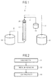
- FIG. 1 is an explanatory diagram illustrating the main construction of an example of the apparatus of the present invention. It should be noted that description is given here by taking the case where a solution containing hydrogen peroxide is treated as an example.
- an apparatus 1 of the present invention includes: a catalyst portion 20 in which a catalyst 10 of the present invention is fixed; a raw water-supplying portion 30 for supplying a solution (raw water) as an object to be treated; a hydrogen peroxide-supplying portion 40 for supplying hydrogen peroxide; and a treated liquid-recovering portion 50 for recovering the solution (treated liquid) treated by the catalyst portion 20.
- the catalyst portion 20 is not particularly limited as long as the catalyst 10 of the present invention is fixed in the portion and the raw water contacts the portion. That is, in the example illustrated in FIG. 1 , the catalyst portion 20 is a tubular body in which the catalyst 10 of the present invention is fixed. A method of fixing the catalyst 10 of the present invention in the catalyst portion 20 is not particularly limited as long as the catalyst 10 of the present invention fixed by the method functions.
- a method involving fixing the catalyst of the present invention to the inner surface of the catalyst portion 20 by coating, or a method involving loading, into the catalyst portion 20, a molded body in which the catalyst of the present invention is fixed (such as the catalyst molded body of the present invention of a pellet-like, fibrous, or plate-like shape) or the catalyst composition of the present invention may be used.
- a liquid-delivering apparatus such as a pump connected to the apparatus 1 of the present invention is operated so that the raw water is made to flow into the catalyst portion 20 from the raw water-supplying portion 30 through a supply channel 31.
- hydrogen peroxide is added to the raw water before its flow into the catalyst portion 20 from the hydrogen peroxide-supplying portion 40 through an addition channel 41. Therefore, the raw water to which hydrogen peroxide has been added flows into the catalyst portion 20.
- the raw water that has flowed into the catalyst portion 20 flows in the catalyst portion 20 while contacting the catalyst 10 of the present invention fixed in the catalyst portion 20.
- the raw water flowing in the catalyst portion 20 is treated by the catalyst 10 of the present invention. That is, an organic substance contained in the raw water is efficiently decomposed by the catalytic activity of the catalyst 10 of the present invention in the presence of hydrogen peroxide.
- the treated liquid that has been treated by the catalyst 10 of the present invention and flowed out of the catalyst portion 20 is recovered by the treated liquid-recovering portion 50 through a recovery channel 21.
- the treated liquid whose organic substance content concentration has been effectively reduced compared with that in the raw water is efficiently obtained with the apparatus 1 of the present invention.
- the construction of the apparatus of the present invention is not limited to the example illustrated in FIG. 1 . That is, the apparatus of the present invention is not required to include any such other construction as illustrated in FIG. 1 as long as the apparatus of the present invention includes the catalyst portion 20 in which the raw water is treated.
- the apparatus of the present invention may be an apparatus that performs the treatment according to a batch mode instead of such an apparatus as illustrated in FIG. 1 which performs a continuous treatment.
- the apparatus of the present invention can treat a gas or a mist containing hydrogen peroxide as in the case of a solution.
- FIG. 2 is an explanatory diagram illustrating main steps in an example of the production method of the present invention.
- the production method of the present invention includes a carbonization step S1, a metal impregnation step S2, and a heat treatment step S3.
- raw materials containing an organic compound as a carbon source, a metal, and an electrically conductive carbon material are carbonized so that a carbonized material is obtained.
- the organic compound in the raw materials is not particularly limited as long as the compound can be carbonized, and one or two or more kinds of arbitrary compounds may be used. That is, one or both of a high-molecular weight organic compound (e.g., a resin such as a thermoplastic resin or a thermosetting resin) and a low-molecular weight organic compound may be used as the organic compound, and biomass may also be used.
- a high-molecular weight organic compound e.g., a resin such as a thermoplastic resin or a thermosetting resin
- biomass may also be used.
- an organic compound containing nitrogen may be preferably used as the organic compound.
- the organic compound containing nitrogen is not particularly limited as long as the compound contains a nitrogen atom in a molecule thereof, and one or two or more kinds of arbitrary compounds may be used.
- a ligand that coordinates to a metal may be preferably used as the organic compound. That is, in this case, an organic compound containing one or more ligand atoms in a molecule thereof is used. More specifically, for example, an organic compound containing, as a ligand atom, one or two or more kinds selected from the group consisting of a nitrogen atom, a phosphorus atom, an oxygen atom, and a sulfur atom in a molecule thereof may be used.
- an organic compound containing, as a ligand group, one or two or more kinds selected from the group consisting of an amino group, a phosphino group, a carboxyl group, and a thiol group in a molecule thereof may also be used.
- one or two or more kinds selected from the group consisting of pyrolle, vinylpyridine, imidazole, 2-methylimidazole, aniline, a polysulfone, a polyaminobismaleimide, a polyimide, a polyvinyl alcohol, a polybenzoimidazole, a polyamide, a polyether, a polyetheretherketone, cellulose, lignin, chitin, chitosan, silk, wool, a polyamino acid, a nucleic acid, DNA, RNA, hydrazine, hydrazide, urea, an ionomer, a polyacrylate, a polyacrylate ester, a polymetacrylate ester, a polymetacrylate, a phenol resin, a melamine resin, an epoxy resin, a furan resin, a polyamideimide resin, and a polyacrylonitrile may be used as the organic compound.
- the organic compound may further contain, for example, one or two or more kinds selected from the group consisting of boron, phosphorus, oxygen, and sulfur as a component for improving the activity of the carbon catalyst to be produced by the production method of the present invention.
- the metal in the raw materials is not particularly limited as long as the metal does not inhibit the activity of the carbon catalyst to be produced by the production method of the present invention, and one or two or more kinds of arbitrary metals may be used.
- the metal may be, for example, one or two or more kinds selected from the group consisting of Groups 3 to 16 of the periodic table.
- Group 3A Group 3A
- Group 4A Group 4A
- Group 5A Group 5A
- Group 6A Group 6A
- Group 7A Group 7) element
- Group 8 Groups 8, 9, and 10 element
- Group 1B Group 11
- Group 2B Group 12
- Group 3B Group 13
- Group 4B Group 14
- Group 5B Group 15
- Group 6B Group 16 element of the periodic table
- a transition metal (belonging to Groups 3 to 12 of the periodic table) may be preferably used as the metal.
- a metal belonging to the fourth period of Groups 3 to 12 of the periodic table may be preferably used as the transition metal.
- the metal may be used as the simple substance of the metal or a compound of the metal.
- a metal salt, a metal oxide, a metal hydroxide, a metal nitride, a metal sulfide, a metal carbide, or a metal complex can be used as the metal compound.
- the metal salt, the metal oxide, the metal sulfide, or the metal complex may be preferably used. It should be noted that when a ligand is used as the organic compound, a metal complex is to be formed in the raw materials.
- the electrically conductive carbon material in the raw materials is not particularly limited as long as the material imparts electrical conductivity to the carbon catalyst to be produced by the production method of the present invention, or improves the electrical conductivity of the carbon catalyst, and one or two or more kinds of arbitrary materials may be used. That is, for example, a carbon material that has electrical conductivity but does not have any catalytic activity by itself may be used as the electrically conductive carbon material.
- one or two or more kinds selected from the group consisting of carbon black, carbon nanotube, carbon nanohorn, carbon fiber, carbon fibril, a graphite powder may be used.
- the electrically conductive carbon material that has been caused to carry the metal in the raw materials in advance may also be used. That is, in this case, for example, an electrically conductive carbon material carrying a transition metal that improves the activity or oxidation resistance of the carbon catalyst may be used.
- the transition metal for example, one or two or more kinds selected from the group consisting of scandium, titanium, vanadium, chromium, manganese, iron, cobalt, nickel, copper, zinc, yttrium, zirconium, niobium, molybdenum, ruthenium, rhodium, palladium, lanthanoids (cerium etc.), and actinoids may be used.
- the raw materials containing such organic compound, metal, and electrically conductive carbon material as described above are mixed.
- a method of mixing the raw materials is not particularly limited, and for example, a mortar or a stirring apparatus may be used.
- One or two or more kinds of mixing methods such as powder mixing involving mixing the organic compound, the metal, and the electrically conductive carbon material in powdery states, and solvent mixing involving adding and mixing a solvent may also be employed.
- the raw materials prepared as described above are carbonized. That is, the raw materials are heated and held at a predetermined temperature such that the raw materials are carbonized (carbonization temperature).
- the carbonization temperature is not particularly limited as long as the raw materials are carbonized at the temperature, and for example, the temperature may be 300°C or more. More specifically, for example, the carbonization temperature may be 300°C or more and 1,500°C or less, may be preferably 400°C or more and 1,200°C or less, and may be more preferably 500°C or more and 1,100°C or less.
- a rate of temperature increase upon heating of the raw materials to the carbonization temperature is not particularly limited and may be, for example, 0.5°C/min or more and 300°C/min or less.
- the time period for which the raw materials are held at the carbonization temperature is not particularly limited as long as the raw materials are carbonized within the time period, and for example, the time may be 5 minutes or more. More specifically, for example, the carbonization time may be 5 minutes or more and 240 minutes or less, and may be preferably 20 minutes or more and 180 minutes or less.
- the carbonization is preferably performed in an inert gas such as nitrogen (e.g., in a flow of the inert gas).
- the carbonized material produced by the carbonization of the raw materials is obtained.
- the resultant carbonized material may be pulverized.
- a method of pulverizing the carbonized material is not particularly limited, and for example, a pulverizing apparatus such as a ball mill or a bead mill may be used.
- the average particle diameter of the carbonized material after the pulverization may be 150 ⁇ m or less, and may be preferably 45 ⁇ m or less.
- a nitrogen atom may be introduced (doped) into the resultant carbonized material.
- a vapor phase doping method such as an ammoxidation method or a CVD method, a liquid phase doping method, or a vapor phase-liquid phase doping method may be employed as a method of introducing a nitrogen atom.
- a nitrogen atom may be introduced into the surface of the carbonized material by: mixing a nitrogen source such as ammonia, melamine, or acetonitrile with the carbonized material; and holding the resultant mixture under the atmosphere of an inert gas such as nitrogen, argon, or helium at a temperature of 550°C or more and 1,200°C or less for a time period of 5 minutes or more and 180 minutes or less.
- a nitrogen source such as ammonia, melamine, or acetonitrile
- an inert gas such as nitrogen, argon, or helium
- the resultant carbonized material may be subjected to an activating treatment such as steam activation, carbon dioxide activation, phosphoric acid activation, alkali activation, hydrogen activation, ammonia activation, activation with nitrogen oxide, or electrolytic activation and/or liquid phase oxidation such as nitric acid oxidation, mixed acid oxidation, or hydrogen peroxide oxidation.
- an activating treatment such as steam activation, carbon dioxide activation, phosphoric acid activation, alkali activation, hydrogen activation, ammonia activation, activation with nitrogen oxide, or electrolytic activation and/or liquid phase oxidation such as nitric acid oxidation, mixed acid oxidation, or hydrogen peroxide oxidation.
- the carbonized material obtained in the carbonization step S1 is impregnated with a metal.
- the metal with which the carbonized material is impregnated is not particularly limited as long as the metal does not inhibit the activity of the carbon catalyst to be produced by the production method of the present invention, and one or two or more kinds of arbitrary metals may be used.
- the metal may be, for example, one or two or more kinds selected from the group consisting of Groups 3 to 16 of the periodic table.
- a transition metal (belonging to Groups 3 to 12 of the periodic table) may be preferably used as the metal.
- a metal belonging to the fourth period, fifth period, or sixth period of Groups 3 to 12 of the periodic table may be preferably used as the transition metal.
- one or two or more kinds selected from the group consisting of titanium, chromium, manganese, iron, cobalt, nickel, copper, zinc, zirconium, niobium, molybdenum, ruthenium, lanthanum, cerium, and tantalum can be preferably used, and one or two or more kinds selected from the group consisting of titanium, iron, zirconium, ruthenium, and cerium may be more preferably used.
- the carbonized material may be impregnated with a metal of a kind different from the metal in the raw materials used in the carbonization step S1. That is, for example, the carbonized material may be impregnated with one or two or more kinds selected from the group consisting of aluminum, silicon, titanium, chromium, manganese, iron, cobalt, nickel, copper, zinc, gallium, zirconium, niobium, molybdenum, ruthenium, indium, tin, lanthanum, cerium, tantalum, and lead or from the group consisting of titanium, iron, zirconium, ruthenium, and cerium, and different from the metal in the raw materials.
- the carbonized material may be impregnated with one or two or more kinds selected from the group consisting of aluminum, silicon, titanium, chromium, manganese, iron, cobalt, nickel, copper, zinc, gallium, zirconium, niobium, molybdenum, ruthenium, indium,
- the metal may be used as the simple substance of the metal or a compound of the metal.
- a metal salt, a metal oxide, a metal hydroxide, a metal nitride, a metal sulfide, a metal carbide, or a metal complex can be used as the metal compound.
- the metal salt, the metal oxide, the metal sulfide, or the metal complex may be preferably used.
- a method of impregnating the carbonized material with the metal in the metal impregnation step S2 is not particularly limited as long as at least the surface of the carbonized material is impregnated with the metal, and for example, a method involving bringing the carbonized material into contact with a solution containing the metal may be employed.
- the carbonized material may be impregnated with the metal by, for example, immersing and holding the carbonized material in a metal-containing solution.
- the carbonized material may be held in the metal-containing solution that has been boiled.
- an acidic solution may be used as the metal-containing solution.
- the pH of the metal-containing solution may be, for example, 1 or more and 6 or less.
- the carbonized material that has been impregnated with the metal in the metal impregnation step S2 is subjected to a heat treatment.
- the heat treatment is performed by holding the carbonized material at a predetermined temperature (heat treatment temperature).
- the carbonized material is heated at, for example, 300°C or more.
- the heat treatment temperature may be, for example, 400°C or more. More specifically, for example, the heat treatment temperature may be 300°C or more and 1,500°C or less, may be preferably 400°C or more and 1,400°C or less, and may be more preferably 500°C or more and 1,300°C or less.
- the heat treatment temperature may be the same temperature as the carbonization temperature, or may be a temperature different from the carbonization temperature. That is, for example, the heat treatment temperature may be a temperature equal to or lower than the carbonization temperature of the raw materials in the carbonization step S1, or may be a temperature lower than the carbonization temperature. Alternatively, the heat treatment temperature may be a temperature higher than the carbonization temperature.
- the heat treatment temperature may be a temperature that is 300 °C or more and 1,000°C or less, and is equal to or lower than the carbonization temperature or is lower than the carbonization temperature.
- a rate of temperature increase upon heating of the carbonized material to the heat treatment temperature is not particularly limited and may be, for example, 0.5°C/min or more and 300°C/min or less.
- the time period for which the carbonized material is held at the heat treatment temperature is not particularly limited as long as an effect of the heat treatment is obtained within the time, and for example, the time may be 5 minutes or more. More specifically, for example, the heat treatment time may be 5 minutes or more and 240 minutes or less, and may be preferably 20 minutes or more and 180 minutes or less.
- the heat treatment is preferably performed in an inert gas such as nitrogen (e.g., in a flow of the inert gas).
- step S3 the carbonized material subjected to the heat treatment after the impregnation with the metal is obtained.
- the resultant carbonized material may be pulverized.
- a method of pulverizing the carbonized material is not particularly limited, and for example, a pulverizing apparatus such as a ball mill or a bead mill may be used.
- the average particle diameter of the carbonized material after the pulverization may be 150 ⁇ m or less, and may be preferably 45 ⁇ m or less.
- the carbonized material obtained in the heat treatment step S3 may be obtained as a carbon catalyst.
- the production method of the present invention including the carbonization step S1, the metal impregnation step S2, and the heat treatment step S3 as described above, a carbon catalyst whose activity has been improved compared with a conventional one is produced. That is, the production method of the present invention effectively improves the activity of the carbon catalyst by including, in particular, the metal impregnation step S2 and the heat treatment step S3.
- the catalytic activity is significantly improved by further subjecting the carbonized material to a metal impregnation treatment and a heat treatment.
- the mechanism via which the activity of the carbon catalyst is improved by the metal impregnation treatment and the heat treatment may be, for example, that a new carbon structure different from a carbon structure formed by the carbonization is formed by the metal impregnation treatment and the heat treatment.
- the metal in the raw materials is placed not only on the surface of the carbonized material but also in the entirety of the inside thereof while being dispersed therein, the metal with which the carbonized material has been impregnated in the metal impregnation step S2 is locally placed mainly on the surface of the carbonized material and a vicinity thereof.
- the metal impregnation treatment and the heat treatment each have an aspect of a surface treatment for the carbonized material.
- the carbon structure formed by the metal impregnation treatment and the heat treatment may be different from the carbon structure formed by the carbonization.
- a treatment for removing a metal in the carbonized material may be performed as required (for example, when the metal is unnecessary after the carbonization).
- the production method of the present invention may further include: a metal removal step of subjecting the carbonized material that has been subjected to the heat treatment in the heat treatment step S3 to a metal removal treatment; and an after-metal removal heat treatment step of subjecting the carbonized material that has been subjected to the metal removal treatment to a heat treatment.
- the metal removal treatment is not particularly limited as long as a metal in the carbonized material is removed or the amount of the metal is reduced by the treatment, and for example, a washing treatment with an acid or an electrolytic treatment may be performed.
- the acid to be used in the acid washing is not particularly limited as long as an effect of the metal removal treatment is obtained, and one or two or more kinds of arbitrary acids may be used. That is, for example, one or two or more kinds selected from the group consisting of hydrochloric acid (such as concentrated hydrochloric acid), nitric acid (such as concentrated nitric acid), and sulfuric acid (such as concentrated sulfuric acid) may be used.
- hydrochloric acid such as concentrated hydrochloric acid
- nitric acid such as concentrated nitric acid
- sulfuric acid such as concentrated sulfuric acid
- a mixed acid prepared by mixing concentrated hydrochloric acid and concentrated nitric acid at a predetermined volume ratio such as aqua regia
- a mixed acid prepared by mixing concentrated nitric acid and concentrated sulfuric acid at a predetermined volume ratio may be used.
- a method for the acid washing is not particularly limited as long as the effect of the metal removal treatment is obtained, and for example, a method involving immersing and holding the carbonized material in a solution containing an acid may be employed. In this case, the carbonized material may be held in a boiling acid solution.
- the same heat treatment as the heat treatment in the heat treatment step 33 is performed.
- a carbonized material subjected to the heat treatment after the metal, removal is obtained.
- the resultant carbonized material may be pulverized as with the carbonized material subjected to the heat treatment in the heat treatment step S3.
- the carbonized material obtained in the after-metal removal heat treatment step may be obtained as a carbon catalyst.
- a carbon catalyst with an additionally improved activity is produced by performing such metal removal treatment and after-metal removal heat treatment. That is, in this case, the activity of the carbon catalyst is effectively improved by, for example, removing a metal component from the carbonized material to expose an active site.
- the metal impregnation treatment may be performed in the metal impregnation step S2 without subjecting the carbonized material obtained in the carbonization step S1 to such metal removal treatment as described above. That is, in this case, in the metal impregnation step S2, the carbonized material is impregnated with the metal without the removal of the metal that had been contained in the raw materials from the carbonized material.
- the metal impregnation treatment may be performed after the carbonized material has been subjected to the metal removal treatment. That is, in this case, in the metal impregnation step S2, the carbonized material from which the metal that had been contained in the raw materials has been removed is impregnated with the metal.
- the production method of the present invention may further include : an additional metal impregnation step of further impregnating the carbonized material that has been subjected to the heat treatment in the heat treatment step S3 with a metal; and an additional heat treatment step of subjecting the carbonized material impregnated with the metal in the additional metal impregnation step to a heat treatment.
- the production method of the present invention includes, for example, the carbonization step S1, the metal impregnation step S2, the heat treatment step S3, the additional metal impregnation step, and the additional heat treatment step.
- the metal with which the carbonized material is impregnated is not particularly limited as long as the metal does not inhibit the activity of the carbon catalyst to be produced by the production method of the present invention, and one or two or more kinds of arbitrary metals may be used.
- the metal may be, for example, one or two or more kinds selected from the group consisting of Groups 3 to 16 of the periodic table.
- a transition metal (belonging to Groups 3 to 12 of the periodic table) may be preferably used as the metal.
- a metal belonging to the fourth period, fifth period, or sixth period of Groups 3 to 12 of the periodic table may be preferably used as the transition metal.
- one or two or more kinds selected from the group consisting of titanium, chromium, manganese, iron, cobalt, nickel, copper, zinc, zirconium, niobium, molybdenum, ruthenium, lanthanum, cerium, and tantalum can be preferably used, and one or two or more kinds selected from the group consisting of titanium, iron, zirconium, ruthenium, and cerium may be more preferably used.
- the carbonized material may be impregnated with ametalofa kind different from the metal in the raw materials used in the carbonization step S1. That is, for example, the carbonizedmaterial may be impregnated with one or two or more kinds selected from the group consisting of aluminum, silicon, titanium, chromium, manganese, iron, cobalt, nickel , copper, zinc, gallium, zirconium, niobium, molybdenum, ruthenium, indium, tin, lanthanum, cerium, tantalum, and lead, or from the group consisting of titanium, iron, zirconium, ruthenium, and cerium, and different from the metal in the raw materials.
- the carbonizedmaterial may be impregnated with one or two or more kinds selected from the group consisting of aluminum, silicon, titanium, chromium, manganese, iron, cobalt, nickel , copper, zinc, gallium, zirconium, niobium, molybdenum, ruthenium, indium
- the carbonized material may be impregnated with a metal of a kind different from the metal with which the material has been impregnated in the metal impregnation step S2. That is, for example, the carbonized material may be impregnated with one or two or more kinds selected from the group consisting of aluminum, silicon, titanium, chromium, manganese, iron, cobalt, nickel, copper, zinc, gallium, zirconium, niobium, molybdenum, ruthenium, indium, tin, lanthanum, cerium, tantalum, and lead, or from the group consisting of titanium, iron, zirconium, ruthenium, and cerium, and different from the metal with which the carbonized material has been impregnated in the metal impregnation step S2.
- the carbonized material may be impregnated with a metal of a kind different from the metal with which the material has been impregnated in the metal impregnation step S2, the metal being capable of having a valence of 4. That is, in this case, for example, the carbonized material is impregnated with a divalent or trivalent metal in the metal impregnation step S2, and then the carbonized material is impregnated with a tetravalent metal in the additional metal impregnation step.
- the metal may be used as the simple substance of the metal or a compound, of the metal.
- a metal salt, a metal oxide, a metal hydroxide, a metal nitride, a metal sulfide, a metal carbide, or a metal complex can be used as the metal compound.
- the metal salt, the metal oxide, the metal sulfide, or the metal complex may be preferably used.
- a method of impregnating the carbonized material with the metal in the additional metal impregnation step is not particularly limited as long as at least the surface of the carbonized material is impregnated with the metal, and for example, a method involving bringing the carbonized material into contact with a solution containing the metal may be employed.
- the carbonized material may be impregnated with the metal by, for example, immersing and holding the carbonized material in a metal-containing solution.
- the carbonized material may be held in the metal-containing solution that has been boiled.
- an acidic solution may be used as the metal-containing solution.
- the pH of the metal-containing solution may be, for example, 1 or more and 6 or less.
- a heat treatment temperature in the additional heat treatment step may be the same temperature as the heat treatment temperature in the heat treatment step S3, or maybe a temperature different from the heat treatment temperature.
- the additional heat treatment step a carbonized material subjected to the heat treatment after the additional metal impregnation treatment is obtained.
- the resultant carbonized material may be pulverized, as in the carbonized material subjected to the heat treatment in the heat treatment step S3.
- the additional metal impregnation step and the additional heat treatment step may each be repeated twice or more.
- the carbonized material obtained in the additional heat treatment step is obtained as a carbon catalyst.
- a carbon catalyst with an additionally improved activity is produced by performing such additional metal impregnation treatment and additional heat treatment. That is, in this case, the activity of the carbon catalyst is effectively improved by, for example, further forming a new carbon structure.
- the production method of the present invention may further include the additional metal impregnation step and the additional heat treatment step, and the metal removal step and the after-metal removal heat treatment step. That is, the production method of the present invention includes, for example, the carbonization step S1, the metal impregnation step S2, the heat treatment step S3, the metal removal step, the after-metal removal heat treatment step, the additional metal impregnation step, and the additional heat treatment step.
- the carbonized material subjected to the metal removal treatment and the after-metal removal heat treatment after the heat treatment in the heat treatment step S3 is impregnated with a metal again.
- the carbonized material after the heat treatment in each additional heat treatment step may be subjected to a metal removal treatment and an after-metal removal heat treatment.
- the production method of the present invention may further include: an acid treatment step of subjecting the carbonized material subjected to the heat treatment in the heat treatment step S3 to an acid treatment; and an after-acid treatment heat treatment step of subjecting the carbonized material subjected to the acid treatment to a heat treatment.
- the production method of the present invention includes, for example, the carbonization step S1, the metal impregnation step S2, the heat treatment step S3, the acid treatment step, and the after-acid treatment heat treatment step.
- An acid to be used in the acid treatment is not particularly limited as long as an effect of the acid treatment is obtained, and one or two or more kinds of arbitrary acid may be used. That is, for example, one or two or more kinds selected from the group consisting of hydrochloric acid (such as concentrated hydrochloric acid), nitric acid (such as concentrated nitric acid), and sulfuric acid (such as concentrated sulfuric acid) may be used.
- hydrochloric acid such as concentrated hydrochloric acid
- nitric acid such as concentrated nitric acid
- sulfuric acid such as concentrated sulfuric acid
- a mixed acid prepared by mixing concentrated hydrochloric acid and concentrated nitric acid at a predetermined volume ratio such as aqua regia
- a mixed acid prepared by mixing concentrated nitric acid and concentrated sulfuric acid at a predetermined volume ratio may be used.
- a method for the acid treatment is not particularly limited as long as the effect of the acid treatment is obtained, and for example, a method involving immersing and holding the carbonized material in a solution containing an acid may be employed.
- the carbonized material may be held in the acid solution that has been boiled.
- the carbonized material may be subjected to an acid treatment by washing the carbonized material with an acid in the metal removal step. That is, the acid washing for metal removal may be a mode of the acid treatment as a surface treatment.
- the same heat treatment as the heat treatment in the heat treatment step S3 is performed.
- a carbonizedmaterial subjected to the heat treatment after the acid treatment is obtained.
- the resultant carbonized material may be pulverized as in the carbonized material subjected to the heat treatment in the heat treatment step S3.
- the acid treatment step and the after-acid treatment heat treatment step may each be repeated twice or more.
- the carbonized material obtained in the after-acid treatment heat treatment step may be obtained as a carbon catalyst.
- a carbon catalyst with an additionally improved activity is produced by performing such acid treatment and after-acid treatment heat treatment. That is, in this case, the activity of the carbon catalyst is effectively improved by, for example, introducing anew functional group on the surface of the carbonized material and the vicinity thereof.
- the production method of the present invention may further include the acid treatment step and the after-acid treatment heat treatment step, and the metal removal step and the after-metal removal heat treatment step. That is, the production method of the present invention includes, for example, the carbonization step S1, the metal impregnation step S2, the heat treatment step S3, the metal removal step, the after-metal removal heat treatment step, the acid treatment step, and the after-acid treatment heat treatment step.
- the carbonized material subjected to the metal removal treatment and the after-metal removal heat treatment after the heat treatment in the heat treatment step S3 is subjected to an acid treatment.
- the acid treatment step and the after-acid treatment heat treatment step are each repeated twice or more, the carbonized material after the heat treatment in each after-acid treatment heat treatment step may be subjected to a metal removal treatment and an after-metal removal heat treatment.
- the catalyst of the present invention may be, for example, a carbon catalyst obtained by: impregnating a carbonized material, which is obtained by the carbonization of raw materials containing an organic compound as a carbon source, a metal, and an electrically conductive carbon material, with a metal; and subjecting the resultant to a heat treatment.
- the catalyst of the present invention is preferably produced by the production method of the present invention. That is, the catalyst of the present invention may be a carbon catalyst produced by the production method of the present invention including, for example, the carbonization step S1, the metal impregnation step S2, and the heat treatment step S3.
- the catalyst of the present invention in this case may also be a carbon catalyst having a carbon structure in which such desorption of carbon monoxide and carbon dioxide as described above occurs in the temperature programmed desorption method.
- a rawmaterial as an object to be carbonized was prepared. That is, 1.5 g of a polyacrylonitrile-polymethacrylic acid copolymer (PAN/PMA) were dissolved in 30 mL of dimethylformamide. After that, 1.5 g of 2-methylimidazole and 1.5 g of cobalt chloride hexahydrate (CoCl 2 ⁇ 6H 2 O) were added to the solution, and then the mixture was stirred at room temperature for 2 hours. Ketjen black (ECP600JD manufactured by Lion Corporation) was added to the mixture thus obtained so as to account for 30 wt% of the solid content to be incorporated into the raw material, and then the contents were mixed with a mortar. The resultant mixture was vacuum-dried at 60°C for 12 hours.
- PAN/PMA polyacrylonitrile-polymethacrylic acid copolymer
- 2-methylimidazole and 1.5 g of cobalt chloride hexahydrate (CoCl 2 ⁇ 6H 2 O)
- the mixture was heated in the atmosphere so that its temperature was increased from room temperature to 150°C in 30 minutes. Subsequently, the temperature was increased from 150°C to 220°C over 2 hours. After that, the mixture was held at 220°C for 3 hours so that the mixture was made infusible.
- the raw material for a carbonized material was prepared.
- the carbonization of the raw material was performed. That is, the raw material subjected to the infusible treatment as described above was loaded into a quartz tube and subjected to nitrogen purge in an image furnace for 20 minutes, and then its temperature was increased from room temperature to 900°C by heating over 18 minutes. After that, the raw material was held at 900°C for 1 hour so as to be carbonized. Thus, a carbonized material was obtained.
- the carbonized material was pulverized. That is, zirconia balls each having a diameter of 10 mm were set in a planetary ball mill (P-7 manufactured by FRITSCH JAPAN CO., LTD.), and then a treatment for pulverizing the carbonized material with the planetary ball mill for 5 minutes at a rotational speed of 650 rpm was performed 10 cycles. After that, the pulverized carbonized material was taken out and passed through a sieve having an aperture of 106 ⁇ m. The carbonized material that had passed the sieve was obtained as a pulverized, fine particulate carbonized, material.
- a metal impregnation treatment was performed. That is, a solution prepared by adding 2 g of iron (III) chloride hexahydrate (FeCl 3 ⁇ 6H 2 O) to 300 mL of distilled water was boiled, and then 2 g of the carbonized material were added to the iron-containing solution. Then, the carbonized material was impregnated with iron for 3 hours while being stirred in the iron-containing solution that was boiling. After that, the solution containing the carbonized material was filtrated with a filtration film (having a pore diameter of 1.0 ⁇ m and manufactured by Millipore), and then the filtrate was washed with distilled water until the filtrate became neutral. The recovered carbonized material was vacuum-dried at 60°C for 12 hours. Further, the dried carbonized material was pulverized with a mortar.
- iron (III) chloride hexahydrate FeCl 3 ⁇ 6H 2 O
- the carbonized material subjected to the metal impregnation treatment as described above was loaded into a quartz tube and subjected to nitrogen purge in an image furnace for 20 minutes, and then its temperature was increased from room temperature to 700°C by heating over 14 minutes. After that, the carbonized material was held at 700°C for 1 hour.
- the carbonized material after the heat treatment was pulverized. That is, zirconia balls each having a diameter of 10 mm were set in a planetary ball mill, and then a treatment for pulverizing the carbonized material with the planetary ball mill for 5 minutes at a rotational speed of 450 rpm was performed over 4 cycles. After that, the pulverized carbonized material was taken out and passed through a sieve having an aperture of 106 ⁇ m. The carbonized material that had passed through the sieve was obtained as a pulverized, fine particulate carbon catalyst for decomposing hydrogen peroxide (PCoFe).
- PCoFe hydrogen peroxide
- the carbon catalyst for decomposing hydrogen peroxide (PCoFe) obtained in the Example 1-1 was subjected to a metal removal treatment by acid washing.
- the solution containing the carbon catalyst was filtrated with a filtration film (having a pore diameter of 1.0 ⁇ m and manufactured by Millipore), and then the filtrate was washed with distilled water until the filtrate became neutral.
- the recovered carbonized material was vacuum-dried at 60°C for 12 hours. Further, the dried carbonized material was pulverized with a mortar.
- an after-metal removal heat treatment was performed. That is, the carbon catalyst subjected to the metal removal treatment as described above was loaded into a quartz tube and subjected to nitrogen purge in an image furnace for 20 minutes, and then its temperature was increased from room temperature to 700°C by heating over 14 minutes. After that, the carbon catalyst was held at 700°C for 1 hour.
- the carbon catalyst after the heat treatment was pulverized. That is, zirconia balls each having a diameter of 10 mm were set in a planetary ball mill, and then a treatment for pulverizing the carbonized, material with the planetary ball mill for 5 minutes at a rotational speed of 450 rpm was performed over 4 cycles. After that, the pulverized carbonized material was taken out and passed through a sieve having an aperture of 106 ⁇ m. The carbonized material that had passed through the sieve was obtained as a pulverized, fine particulate carbon catalyst for decomposing hydrogen peroxide (PCoFeAW).
- PCoFeAW hydrogen peroxide
- a carbon catalyst (CoFeAW) was produced in the same manner as in the Example 1-2 except that the following raw material free of the PAN/PMA was used as a raw material for a carbonized material.
- the carbon catalyst for decomposing hydrogen peroxide (PCoFeAW) obtained in the Example 1-2 was subjected to an additional metal impregnation treatment.
- a solution prepared by adding 2 g of zirconium chloride oxide octahydrate (ZrCl 2 O ⁇ 8H 2 O) to 300 mL of distilled water was boiled, and then 2 g of the carbon catalyst (PCoFeAW) were added to the zirconium-containing solution. Then, the carbon catalyst was impregnated with zirconium for 3 hours while being stirred in the zirconium-containing solution that was boiling. After that, the solution containing the carbon catalyst was filtrated with a filtration film (having a pore diameter of 1.0 ⁇ m and manufactured by Millipore), and then the filtrate was washed with distilled water until the filtrate became neutral. The recovered carbon catalyst was vacuum-dried at 60°C for 12 hours. Further, the dried carbon catalyst was pulverized with a mortar.
- PCoFeAW carbon catalyst
- the carbon catalyst subjected to the additional metal impregnation treatment as described above was loaded into a quartz tube and subjected to nitrogen purge in an image furnace for 20 minutes, and then its temperature was increased from room temperature to 700°C by heating over 14 minutes. After that, the carbon catalyst was held at 700°C for 1 hour.
- the carbon catalyst after the heat treatment was pulverized. That is, zirconia balls each having a diameter of 1.5 mm were set in a planetary ball mill, and then a treatment for pulverizing the carbon catalyst with the planetary ball mill for 5 minutes at a rotational speed of 450 rpm was performed over 4 cycles. After that, the pulverized carbon catalyst was taken out and passed through a sieve having an aperture of 106 ⁇ m. The carbon catalyst that had passed through the sieve was obtained as a pulverized, fine particulate carbon catalyst for decomposing hydrogen peroxide (PCoFeAWZr).
- PCoFeAWZr hydrogen peroxide
- the carbon catalyst for decomposing hydrogen peroxide (PCoFeAW) obtained in the Example 1-2 was subjected to an acid treatment.
- an after-acid treatment heat treatment was performed. That is, the carbon catalyst subjected to the acid treatment as described above was loaded into a quartz tube and subjected to nitrogen purge in an image furnace for 20 minutes, and then its temperature was increased from room temperature to 700°C by heating over 14 minutes. After that, the carbon catalyst was held at 700°C for 1 hour.
- the carbon catalyst after the heat treatment was pulverized. That is, zirconia balls each having a diameter of 10 mm were set in a planetary ball mill, and then a treatment for pulverizing the carbon catalyst with the planetary ball mill for 5 minutes at a rotational speed of 450 rpm was performed over 4 cycles. After that, the pulverized carbon catalyst was taken out and passed through a sieve having an aperture of 106 ⁇ m. The carbon catalyst that hadpassed through the sieve was obtained as a pulverized, fine particulate carbon catalyst for decomposing hydrogen peroxide (PCoFeAWHNO 3 ).
- PCoFeAWHNO 3 fine particulate carbon catalyst for decomposing hydrogen peroxide
- PCoAW pulverized, fine particulate carbon catalyst
- Manganese dioxide (FMV manufactured by TOSOH CORPORATION) was prepared as a catalyst according to Comparative Example 1-2.
- Ketjen black (ECP600JD, Lion Corporation) as an electrically conducive carbon material was prepared as a carbonized material according to Comparative Example 1-3.
- the carbon catalysts for decomposing hydrogen peroxide produced in the Examples 1-2 to 1-5, the carbon catalyst produced in the Comparative Example 1-1, and the ketjen black (KB) prepared in the Comparative Example 1-3 were each evaluated by a temperature programmed desorption method. That is, a carbon catalyst was placed in a temperature programmed desorption apparatus (manufactured by BEL Japan, Inc.), the carbon catalyst was heated under a high vacuum such that a carrier gas (He) was made to flow at 50 mL/min, and a desorbed gas was subjected to measurement with a quadrupole mass spectrometer (QMS).
- a temperature programmed desorption apparatus manufactured by BEL Japan, Inc.
- the carbon catalyst was subjected to a pretreatment (desorption of a catalyst surface functional group by a heat treatment). That is, 0.02 g of the carbon catalyst was loaded into the central portion of a reaction tube made of quartz, and then the tube was set in the temperature programmed desorption apparatus. The temperature in the apparatus was increased to 50°C at a rate of temperature increase of 5°C/min and then held at the temperature for 40 minutes so that the apparatus was stabilized. After that, the carbon catalyst was subjected to the heat treatment by heating the carbon catalyst to increase its temperature to 900°C at a rate of temperature increase of 10°C/min. Thus, the functional group on its surface was desorbed.
- a pretreatment desorption of a catalyst surface functional group by a heat treatment
- the surface of the carbon catalyst was caused to adsorb oxygen. That is, first, the temperature in the apparatus was held at 150°C for 10 minutes so that the apparatus was stabilized. After that, an oxygen (O 2 ) gas was made to flow through the carbon catalyst subjected to the heat treatment as described above so as to have a concentration of 5 vol%, and then the carbon catalyst was held at 150°C for 20 minutes so that the surface of the carbon catalyst (mainly an edge surface) was caused to chemically adsorb oxygen.
- O 2 oxygen
- the carbon catalyst was subjected to a heat treatment, and then desorbed carbon monoxide (CO) and carbon dioxide (CO 2 ) were subjected to measurement. That is, a helium (He) gas was made to flow in the apparatus at 150°C for 25 minutes so that oxygen that had not chemically adsorbed was deaerated. Next, the temperature in the apparatus was increased from 150°C to 900°C at a rate of temperature increase of 10°C/min again.
- a helium (He) gas was made to flow in the apparatus at 150°C for 25 minutes so that oxygen that had not chemically adsorbed was deaerated.
- He helium
- the helium (He) gas was made to flow at 50 mL/min, carbon monoxide and carbon dioxide produced by the desorption of an oxygen-containing compound were detected, and a correlation between a temperature (axis of abscissa) and a detected intensity (axis of ordinate) was recorded.
- the amounts of desorbed carbon monoxide and carbon dioxide were determined. That is, the integral values (detected intensity areas) of the detected intensities of carbon monoxide and carbon dioxide from 150°C at which the heat treatment was initiated to the temperature (400°C or 900°C) at which it was wished to determine the amounts were each calculated. Meanwhile, a calibration curve illustrating a correlation between the desorption amount of each of carbon monoxide and carbon dioxide, and its detected intensity area, was created by using a predetermined amount of calcium oxalate monohydrate (CaC 2 O 4 ⁇ H 2 O) as a reference substance.
- CaC 2 O 4 ⁇ H 2 O calcium oxalate monohydrate
- the calibration curve was obtained by subjecting 0.02 g of a sample, which was obtained by mixing alumina and calcium oxalate monohydrate (CaC 2 O4 ⁇ H 2 O) so that the content of calcium oxalate was 250, 500, 750, or 1, 000 ⁇ mol, to a heat treatment under the condition described above. Then, the desorption amounts (release amounts) of carbon monoxide and carbon dioxide from the carbon catalyst were determined on the basis of the detected intensity areas obtained by the measurement and the calibration curve.
- FIG. 3 illustrates the results of the evaluations of the respective carbon catalysts for their desorption amounts of carbon monoxide and carbon dioxide in the temperature programmed desorption method from 150°C to 400°C or 900°C.
- the desorption amounts of each of the carbon catalysts for decomposing hydrogen peroxide that were subjected to a metal impregnation treatment (Examples 1-2 to 1-5) were significantly larger than those of the carbon catalysts that were not subjected to the metal impregnation treatment (Comparative Example 1-1) and the electrically conductive carbon material (Comparative Example 1-3). That is, the metal impregnation treatment significantly increased the desorption amounts of carbon monoxide and carbon dioxide in the temperature programmed desorption method.
- PIG. 4 illustrates the result of such evaluation of each catalyst for its catalytic performance on the decomposition of hydrogen peroxide as described above.
- Examples 2-2 to 2-4 in the case where any one of the carbon catalysts for decomposing hydrogen peroxide was used (Examples 2-2 to 2-4), a high decomposition ratio of hydrogen peroxide was achieved compared with that in the case where one of the manganese dioxide catalyst according to Comparative Example 2-1 and the carbon catalyst according to Comparative Example 2-2 was used. That is, it was confirmed that the carbon catalysts for decomposing hydrogen peroxide used in the Examples 2-2 to 2-4 each had a significantly greater catalytic activity on the decomposition of hydrogen peroxide than those of the catalysts used in the Comparative Examples 2-1 and 2-2.
- a polyvinyl butyral (PVB) solution prepared by dissolving a PVB 1000 (polymerization degree: 900 to 1,100, manufactured by Wako Pure Chemical Industries, Ltd.) as a water-insoluble polymer in methanol so that its concentration was 10 wt%, and a polyacrylic acid (PMA) solution prepared by dissolving a PMA (Mw 25,000, manufactured by Wako Pure Chemical Industries, Ltd.) as a water-soluble polymer in methanol so that its concentration was 10 wt% were mixed at a volume ratio of 4:1.
- PMA polyacrylic acid
- the carbon catalyst for decomposing hydrogen peroxide (PCoFeAW) produced in the Example 1-2 was added to the polymer binder solution so that its concentration was 50 wt%, and then the contents were mixed.
- catalyst slurry (catalyst composition for application) was prepared.
- the catalyst slurry was coated on the surface of a substrate having a surface area of 1 cm 2 and then dried.
- a molded body formed of the catalyst and the polymer binder was produced.
- the molded body was immersed in water so that the polyacrylic acid was eluted from the molded body.
- a film-like catalyst molded body for decomposing hydrogen peroxide having a porous structure formed by the removal of the polyacrylic acid was obtained.
- a film-like, manganese dioxide-containing catalyst molded body having a porous structure formed by the removal of the polyacrylic acid was obtained in the same manner as in the catalyst molded body for decomposing hydrogen peroxide, except that manganese dioxide (FMV manufactured by TOSOH CORPORATION) (MnO 2 ) was used instead of the carbon catalyst for decomposing hydrogen peroxide.
- FMV manufactured by TOSOH CORPORATION MnO 2
- the catalyst molded body for decomposing hydrogen peroxide obtained as described above was immersed in an aqueous solution containing hydrogen peroxide at a concentration of 3,000 mg/L, and then the mixture was held at room temperature (27°C) for 120 minutes. Immediately after a lapse of 120 minutes, the catalyst molded body for decomposing hydrogen peroxide was taken out of the aqueous solution of hydrogen peroxide. Then, the concentration of hydrogen peroxide incorporated into the aqueous solution after the treatment was determined by permanganic acid titration, and then the decomposition ratio of hydrogen peroxide was calculated in the same manner as in the Example 1. As a result, the decomposition ratio of hydrogen peroxide was 36%.
- the aqueous solution of hydrogen peroxide was treated in the same manner as in the foregoing except that the manganese dioxide-containing catalyst molded body obtained as described above was used instead of the catalyst molded body for decomposing hydrogen peroxide.
- the decomposition ratio of hydrogen peroxide was 14%.
- the catalyst molded body containing the carbon catalyst for decomposing hydrogen peroxide had a higher catalytic activity on the decomposition of hydrogen peroxide than the catalyst molded body containing manganese dioxide did.
- Waste water having a pH of 6.5 to 7.5 was prepared as raw water as an object to be treated.
- the filtrate obtained by filtrating the raw water to remove a suspended substance had a CODMn of 53 mg/L, a CODCr of 99 mg/L, a TOC of 54 mg/L, and a chromaticity of 391.
- the BOD of the filtrate obtained by subjecting the raw water to centrifugal separation at 10,000 rpm for 10 minutes to remove the suspended substance was 40 mg/L.
- the CODMn was measured by a method in conformity with JIS K 0102-17 and the CODCr was measured by a method in conformity with JIS K 0102-20.
- the TOC was measured with a water quality analyzer (DR2400) manufactured by HATCH by a method in conformity with a TOC (moderate concentration) measurement method with a management number of 10173, and the chromaticity was measured with the water quality analyzer by a method in conformity with a chromaticity measurement method (platinum-cobalt standard method) with a management number of 8025.
- the raw water was treated with a carbon catalyst for decomposing hydrogen peroxide. That is, first, 200 mL of the raw water were charged into a container having a volume of 500 mL.
- the carbon catalyst PCoFeAW for decomposing hydrogen peroxide produced in the Example 1-2 was added to the raw water so that its concentration was 400 mg/L. Further, 2 mL of hydrogen peroxide water adjusted in advance so that its concentration in the raw water was 100 mg/L were added.
- the raw water containing the carbon catalyst and hydrogen peroxide was shaken at room temperature (27°C) for 15 minutes. After the shaking, the treated liquid was filtrated with a filter having a pore diameter of 0.45 ⁇ m so that the carbon catalyst was separated. The CODMn, CODCr, TOC, and chromaticity of the resultant filtrate were measured.
- the raw water was treated with the carbon catalyst PCoFeAW for decomposing hydrogen peroxide in the same manner as in the Example 4-1 except that hydrogen peroxide water adjusted in advance so that its concentration in the raw water was 500 mg/L was added.
- the raw water was treated with the carbon catalyst PCoFeAW for decomposing hydrogen peroxide in the same manner as in the Example 4-2 except that before the addition of the carbon catalyst for decomposing hydrogen peroxide, sulfuric acid was added to the raw water to adjust its pH to 3 to 4.
- the raw water was treated by the Fenton method. That is, first, sulfuric acid was added to the raw water to adjust its pH to 3 to 4. 200 Milliliters of the raw water were charged into a container having a volume of 500 mL. Next, iron (II) chloride (FeCl 2 ) was added to the raw water so that its concentration in the raw water was 400 mg/L. Further, 2 mL of hydrogen peroxide water adjusted in advance so that its concentration in the raw water was 100 mg/L were added.
- sulfuric acid was added to the raw water to adjust its pH to 3 to 4. 200 Milliliters of the raw water were charged into a container having a volume of 500 mL.
- iron (II) chloride (FeCl 2 ) was added to the raw water so that its concentration in the raw water was 400 mg/L. Further, 2 mL of hydrogen peroxide water adjusted in advance so that its concentration in the raw water was 100 mg/L were added.
- the raw water containing iron (II) chloride and hydrogen peroxide was shaken at room temperature (27°C) for 15 minutes. After the shaking, sodium hydroxide was added to the treated liquid so that iron was precipitated as a hydroxide. Next, the treated liquid was filtrated with filter paper (ADVANTEC 5C) so that the precipitate was removed. The filtrate was further filtrated with a filter having a pore diameter of 0.45 ⁇ m. The CODMn, CODCr, TOC, and chromaticity of the resultant filtrate were measured.
- the raw water was treated by the Fenton method in the same manner as in the Example 4-1 except that hydrogen peroxide water adjusted in advance so that its concentration in the raw water was 500 mg/L was added.
- the raw water was treated with manganese dioxide (MnO 2 ) in the same manner as in the Example 4-1 except that the manganese dioxide was used instead of the carbon catalyst.
- MnO 2 manganese dioxide
- the raw water was treated with cobalt oxide (CoO) in the same manner as in the Example 4-2 except that the cobalt oxide was used instead of the carbon catalyst.
- CoO cobalt oxide
- FIG. 5 illustrates the result of an evaluation for a catalytic activity on a water quality improvement in each example together with treatment conditions. It should be noted that the symbol “-" illustrated in the column “CODCr” of FIG. 5 means that no measurement was performed.
- the use of the carbon catalyst for decomposing hydrogen peroxide was able to effectively reduce the CODMn, CODCr, TOC, and chromaticity of the raw water (Examples 4-1 to 4-3). That is, it was confirmed that the carbon catalyst for decomposing hydrogen peroxide showed a significant catalytic activity on the decomposition of an organic substance in the presence of hydrogen peroxide.
Landscapes
- Chemical & Material Sciences (AREA)
- Engineering & Computer Science (AREA)
- Organic Chemistry (AREA)
- Materials Engineering (AREA)
- Chemical Kinetics & Catalysis (AREA)
- Nanotechnology (AREA)
- Physics & Mathematics (AREA)
- Environmental & Geological Engineering (AREA)
- Life Sciences & Earth Sciences (AREA)
- Hydrology & Water Resources (AREA)
- Thermal Sciences (AREA)
- Water Supply & Treatment (AREA)
- Composite Materials (AREA)
- Condensed Matter Physics & Semiconductors (AREA)
- General Physics & Mathematics (AREA)
- Crystallography & Structural Chemistry (AREA)
- Inorganic Chemistry (AREA)
- Catalysts (AREA)
- Removal Of Specific Substances (AREA)
- Treatment Of Water By Oxidation Or Reduction (AREA)
Applications Claiming Priority (3)
| Application Number | Priority Date | Filing Date | Title |
|---|---|---|---|
| JP2009254059 | 2009-11-05 | ||
| JP2010094509 | 2010-04-15 | ||
| PCT/JP2010/067237 WO2011055604A1 (ja) | 2009-11-05 | 2010-10-01 | 炭素触媒及びその用途 |
Publications (2)
| Publication Number | Publication Date |
|---|---|
| EP2497572A1 true EP2497572A1 (de) | 2012-09-12 |
| EP2497572A4 EP2497572A4 (de) | 2015-03-18 |
Family
ID=43969844
Family Applications (1)
| Application Number | Title | Priority Date | Filing Date |
|---|---|---|---|
| EP10828164.3A Withdrawn EP2497572A4 (de) | 2009-11-05 | 2010-10-01 | Kohlenstoffkatalysator und seine verwendung |
Country Status (6)
| Country | Link |
|---|---|
| US (1) | US8372781B2 (de) |
| EP (1) | EP2497572A4 (de) |
| JP (1) | JP5167418B2 (de) |
| CN (1) | CN102596400B (de) |
| CA (1) | CA2779390A1 (de) |
| WO (1) | WO2011055604A1 (de) |
Cited By (1)
| Publication number | Priority date | Publication date | Assignee | Title |
|---|---|---|---|---|
| EP3053879A1 (de) * | 2013-09-30 | 2016-08-10 | Zeon Corporation | Kohlenstoffnanoröhrchen, dispersionsflüssigkeit davon, kohlenstoffnanoröhrchenhaltige folie und zusammensetzungsmaterial |
Families Citing this family (13)
| Publication number | Priority date | Publication date | Assignee | Title |
|---|---|---|---|---|
| WO2011055739A1 (ja) * | 2009-11-05 | 2011-05-12 | 国立大学法人群馬大学 | 炭素触媒並びにその製造方法及びこれを用いた電極並びに電池 |
| JP5193274B2 (ja) * | 2010-11-29 | 2013-05-08 | 国立大学法人群馬大学 | 水素生成用炭素触媒及びその製造方法並びにこれを用いて水素を生成する方法 |
| TW201416330A (zh) * | 2012-10-23 | 2014-05-01 | Mega Union Technology Inc | 廢水處理方法及其設備 |
| CN102910725A (zh) * | 2012-11-20 | 2013-02-06 | 哈尔滨工业大学 | 改进的芬顿、类芬顿体系去除水中有机污染物的方法 |
| JP6164067B2 (ja) * | 2013-11-29 | 2017-07-19 | 日本ゼオン株式会社 | カーボンナノチューブ及びその分散液、並びに自立膜及び複合材料 |
| WO2016088716A1 (ja) * | 2014-12-05 | 2016-06-09 | 日清紡ホールディングス株式会社 | 炭素触媒、電極及び電池 |
| JP6936991B2 (ja) * | 2016-06-02 | 2021-09-22 | 日清紡ホールディングス株式会社 | 炭素触媒、電池電極及び電池 |
| CN106587315A (zh) * | 2017-01-05 | 2017-04-26 | 煤炭科学研究总院杭州研究院 | 一种催化废水中过氧化物分解的循环处理系统及方法 |
| CN107774261B (zh) * | 2017-11-01 | 2022-03-11 | 枣庄学院 | 一种非均相类Fenton催化剂Co/C复合材料的制备方法 |
| CN113042063A (zh) * | 2021-03-23 | 2021-06-29 | 苏州禹江河智能科技有限公司 | 一种废水处理碳化结晶催化剂制备方法 |
| CN113070065B (zh) * | 2021-04-02 | 2023-01-24 | 中国科学院合肥物质科学研究院 | 空心无定型钴碳化物类Fenton催化剂及其制备方法与应用 |
| CN113461110B (zh) * | 2021-06-10 | 2022-08-09 | 同济大学 | 一种基于非自由基氧化的反应性电催化膜及其制备方法和应用 |
| CN117065759A (zh) * | 2023-05-12 | 2023-11-17 | 扬州优境环境工程有限公司 | 一种处理工业废水或废气用活性炭负载金属催化剂及其制备方法 |
Family Cites Families (9)
| Publication number | Priority date | Publication date | Assignee | Title |
|---|---|---|---|---|
| DE69102405T2 (de) | 1990-12-13 | 1994-09-29 | Mitsubishi Gas Chemical Co | Aktivkohlesubstanz, Herstellungsverfahren und Anwendung. |
| JPH05811A (ja) | 1990-12-13 | 1993-01-08 | Mitsubishi Gas Chem Co Inc | 活性炭素材料およびその製造法ならびに用途 |
| JP3539435B2 (ja) | 1993-12-09 | 2004-07-07 | 三菱瓦斯化学株式会社 | 高性能炭素材料の製法 |
| KR20020043946A (ko) * | 2000-12-05 | 2002-06-12 | 이근석 | 산화 촉매 및 그 제조방법, 그 산화 촉매를 재활용하는방법 및 그 산화 촉매를 이용한 폐수 처리 방법 |
| JP2003266081A (ja) | 2002-03-14 | 2003-09-24 | Unitika Ltd | 過酸化水素分解用活性炭及び過酸化水素含有排水の処理方法 |
| JP3975362B2 (ja) | 2004-03-11 | 2007-09-12 | 協同組合ラテスト | 触媒活性炭 |
| JP5124946B2 (ja) * | 2006-01-12 | 2013-01-23 | 栗田工業株式会社 | 超純水製造装置における超純水中の過酸化水素の除去方法 |
| JP5232999B2 (ja) * | 2007-05-11 | 2013-07-10 | 国立大学法人群馬大学 | 炭素系燃料電池用電極触媒の製造方法 |
| JP2009090178A (ja) | 2007-10-05 | 2009-04-30 | Kyodo Kumiai Latest | 過酸化水素分解触媒活性炭 |
-
2010
- 2010-10-01 JP JP2011539320A patent/JP5167418B2/ja active Active
- 2010-10-01 CN CN201080050079.9A patent/CN102596400B/zh not_active Expired - Fee Related
- 2010-10-01 US US13/505,066 patent/US8372781B2/en not_active Expired - Fee Related
- 2010-10-01 EP EP10828164.3A patent/EP2497572A4/de not_active Withdrawn
- 2010-10-01 CA CA2779390A patent/CA2779390A1/en not_active Abandoned
- 2010-10-01 WO PCT/JP2010/067237 patent/WO2011055604A1/ja active Application Filing
Non-Patent Citations (1)
| Title |
|---|
| See references of WO2011055604A1 * |
Cited By (2)
| Publication number | Priority date | Publication date | Assignee | Title |
|---|---|---|---|---|
| EP3053879A1 (de) * | 2013-09-30 | 2016-08-10 | Zeon Corporation | Kohlenstoffnanoröhrchen, dispersionsflüssigkeit davon, kohlenstoffnanoröhrchenhaltige folie und zusammensetzungsmaterial |
| EP3053879A4 (de) * | 2013-09-30 | 2017-03-29 | Zeon Corporation | Kohlenstoffnanoröhrchen, dispersionsflüssigkeit davon, kohlenstoffnanoröhrchenhaltige folie und zusammensetzungsmaterial |
Also Published As
| Publication number | Publication date |
|---|---|
| EP2497572A4 (de) | 2015-03-18 |
| CN102596400A (zh) | 2012-07-18 |
| JPWO2011055604A1 (ja) | 2013-03-28 |
| CA2779390A1 (en) | 2011-05-12 |
| US8372781B2 (en) | 2013-02-12 |
| JP5167418B2 (ja) | 2013-03-21 |
| WO2011055604A1 (ja) | 2011-05-12 |
| CN102596400B (zh) | 2014-12-24 |
| US20120214662A1 (en) | 2012-08-23 |
Similar Documents
| Publication | Publication Date | Title |
|---|---|---|
| US8372781B2 (en) | Carbon catalyst and use thereof | |
| Lim et al. | Activation of peroxymonosulfate by oxygen vacancies-enriched cobalt-doped black TiO2 nanotubes for the removal of organic pollutants | |
| Gopinath et al. | Strategies to design modified activated carbon fibers for the decontamination of water and air | |
| Monama et al. | Palladium deposition on copper (II) phthalocyanine/metal organic framework composite and electrocatalytic activity of the modified electrode towards the hydrogen evolution reaction | |
| Lee et al. | Green approach for photocatalytic Cu (II)-EDTA degradation over TiO2: toward environmental sustainability | |
| Feng et al. | How nitrogen and sulfur doping modified material structure, transformed oxidation pathways, and improved degradation performance in peroxymonosulfate activation | |
| CA2781989C (en) | Carbon catalyst for decomposition of hazardous substance, hazardous-substance-decomposing material, and method for decomposition of hazardous substance | |
| Chen et al. | Studies on the photocatalytic performance of cuprous oxide/chitosan nanocomposites activated by visible light | |
| Yao et al. | Nitrogen-doped carbon encapsulating molybdenum carbide and nickel nanostructures loaded with PVDF membrane for hexavalent chromium reduction | |
| Wang et al. | Nanodenitrification with bimetallic nanoparticles confined in N-doped mesoporous carbon | |
| Liu et al. | Efficient nitrate reduction over novel covalent Ag-salophen polymer-derived “vein-leaf-apple”-like Ag@ carbon structures | |
| Li et al. | Self-cleaning photocatalytic PVDF membrane loaded with NH2-MIL-88B/CDs and Graphene oxide for MB separation and degradation | |
| Zhuang et al. | Nitrogen-doped graphene-based catalyst with metal-reduced organic framework: Chemical analysis and structure control | |
| Lv et al. | Defective layered double hydroxide nanosheet boosts electrocatalytic hydrodechlorination reaction on supported palladium nanoparticles | |
| Liu et al. | Synergistic activation of peroxymonosulfate via oxygen vacancy-rich CoxMn3-xO4/montmorillonite catalyst for environmental remediation | |
| Shi et al. | Confined ultrasmall MOF nanoparticles anchored on a 3D-graphene network as efficient and broad pH-adaptive photo Fenton-like catalysts | |
| Kogularasu et al. | Unlocking catalytic potential: exploring the impact of thermal treatment on enhanced electrocatalysis of nanomaterials | |
| Li et al. | Transition-metal ion-doped flower-like titania nanospheres as nonlight-driven catalysts for organic dye degradation with enhanced performances | |
| Zhang et al. | A confined expansion pore-making strategy to transform Zn-MOF to porous carbon nanofiber for water treatment: Insight into formation and degradation mechanism | |
| Ma et al. | Cobalt leaching inhibition: Transforming coordination polymers into spherical Co3O4@ NC catalysts for accelerated tetracycline degradation via enhanced PMS activation | |
| Farhan et al. | Progress in layered double hydroxides (LDHs): Synthesis and application in adsorption, catalysis and photoreduction | |
| CN113198515A (zh) | 一种三元光催化剂及其制备方法与应用 | |
| Meng et al. | Nitrogen doped carbon with metal as electrocatalysts for the oxygen reduction reaction | |
| RU2446009C1 (ru) | Способ приготовления платино-рутениевых электрокатализаторов | |
| Jin et al. | The construction of a palladium–hydrogen accelerated catalytic Fenton system enhanced by UiO-66 (Zr) |
Legal Events
| Date | Code | Title | Description |
|---|---|---|---|
| PUAI | Public reference made under article 153(3) epc to a published international application that has entered the european phase |
Free format text: ORIGINAL CODE: 0009012 |
|
| 17P | Request for examination filed |
Effective date: 20120604 |
|
| AK | Designated contracting states |
Kind code of ref document: A1 Designated state(s): AL AT BE BG CH CY CZ DE DK EE ES FI FR GB GR HR HU IE IS IT LI LT LU LV MC MK MT NL NO PL PT RO RS SE SI SK SM TR |
|
| DAX | Request for extension of the european patent (deleted) | ||
| A4 | Supplementary search report drawn up and despatched |
Effective date: 20150218 |
|
| RIC1 | Information provided on ipc code assigned before grant |
Ipc: B01J 37/00 20060101ALI20150212BHEP Ipc: C02F 1/72 20060101ALI20150212BHEP Ipc: B01J 23/75 20060101AFI20150212BHEP Ipc: C01B 31/02 20060101ALI20150212BHEP |
|
| 17Q | First examination report despatched |
Effective date: 20160610 |
|
| STAA | Information on the status of an ep patent application or granted ep patent |
Free format text: STATUS: THE APPLICATION IS DEEMED TO BE WITHDRAWN |
|
| 18D | Application deemed to be withdrawn |
Effective date: 20161021 |