WO2011055604A1 - 炭素触媒及びその用途 - Google Patents
炭素触媒及びその用途 Download PDFInfo
- Publication number
- WO2011055604A1 WO2011055604A1 PCT/JP2010/067237 JP2010067237W WO2011055604A1 WO 2011055604 A1 WO2011055604 A1 WO 2011055604A1 JP 2010067237 W JP2010067237 W JP 2010067237W WO 2011055604 A1 WO2011055604 A1 WO 2011055604A1
- Authority
- WO
- WIPO (PCT)
- Prior art keywords
- catalyst
- hydrogen peroxide
- carbon
- metal
- carbon catalyst
- Prior art date
Links
- 239000003054 catalyst Substances 0.000 title claims abstract description 334
- OKTJSMMVPCPJKN-UHFFFAOYSA-N Carbon Chemical compound [C] OKTJSMMVPCPJKN-UHFFFAOYSA-N 0.000 title claims abstract description 206
- 229910052799 carbon Inorganic materials 0.000 title claims abstract description 189
- MHAJPDPJQMAIIY-UHFFFAOYSA-N Hydrogen peroxide Chemical group OO MHAJPDPJQMAIIY-UHFFFAOYSA-N 0.000 claims abstract description 305
- 229910052751 metal Inorganic materials 0.000 claims abstract description 186
- 239000002184 metal Substances 0.000 claims abstract description 186
- 238000010438 heat treatment Methods 0.000 claims abstract description 124
- 239000005539 carbonized material Substances 0.000 claims abstract description 116
- 238000000354 decomposition reaction Methods 0.000 claims abstract description 94
- 239000002994 raw material Substances 0.000 claims abstract description 39
- 150000002894 organic compounds Chemical class 0.000 claims abstract description 21
- 239000003575 carbonaceous material Substances 0.000 claims abstract description 15
- 238000000034 method Methods 0.000 claims description 87
- 239000000243 solution Substances 0.000 claims description 63
- CURLTUGMZLYLDI-UHFFFAOYSA-N Carbon dioxide Chemical compound O=C=O CURLTUGMZLYLDI-UHFFFAOYSA-N 0.000 claims description 62
- 238000003795 desorption Methods 0.000 claims description 55
- 238000003763 carbonization Methods 0.000 claims description 45
- UGFAIRIUMAVXCW-UHFFFAOYSA-N Carbon monoxide Chemical compound [O+]#[C-] UGFAIRIUMAVXCW-UHFFFAOYSA-N 0.000 claims description 32
- 229910002091 carbon monoxide Inorganic materials 0.000 claims description 32
- 239000007789 gas Substances 0.000 claims description 32
- 229910002092 carbon dioxide Inorganic materials 0.000 claims description 31
- 239000001569 carbon dioxide Substances 0.000 claims description 31
- 239000000203 mixture Substances 0.000 claims description 26
- 229920003169 water-soluble polymer Polymers 0.000 claims description 23
- 239000003595 mist Substances 0.000 claims description 22
- 229920005596 polymer binder Polymers 0.000 claims description 22
- 239000002491 polymer binding agent Substances 0.000 claims description 22
- 239000000126 substance Substances 0.000 claims description 18
- 239000007864 aqueous solution Substances 0.000 claims description 14
- 229920003176 water-insoluble polymer Polymers 0.000 claims description 14
- 238000012545 processing Methods 0.000 claims description 10
- 229920002125 Sokalan® Polymers 0.000 claims description 8
- 239000004584 polyacrylic acid Substances 0.000 claims description 8
- 239000004372 Polyvinyl alcohol Substances 0.000 claims description 4
- 229920002451 polyvinyl alcohol Polymers 0.000 claims description 4
- 239000002202 Polyethylene glycol Substances 0.000 claims description 3
- 229920001223 polyethylene glycol Polymers 0.000 claims description 3
- 229920000642 polymer Polymers 0.000 claims 1
- 239000002195 soluble material Substances 0.000 claims 1
- 230000003197 catalytic effect Effects 0.000 abstract description 26
- 238000010000 carbonizing Methods 0.000 abstract 1
- XLYOFNOQVPJJNP-UHFFFAOYSA-N water Substances O XLYOFNOQVPJJNP-UHFFFAOYSA-N 0.000 description 63
- 238000005470 impregnation Methods 0.000 description 54
- 238000004519 manufacturing process Methods 0.000 description 45
- XEEYBQQBJWHFJM-UHFFFAOYSA-N Iron Chemical compound [Fe] XEEYBQQBJWHFJM-UHFFFAOYSA-N 0.000 description 35
- 238000010306 acid treatment Methods 0.000 description 31
- NUJOXMJBOLGQSY-UHFFFAOYSA-N manganese dioxide Chemical compound O=[Mn]=O NUJOXMJBOLGQSY-UHFFFAOYSA-N 0.000 description 30
- 230000000694 effects Effects 0.000 description 26
- 230000008569 process Effects 0.000 description 26
- IJGRMHOSHXDMSA-UHFFFAOYSA-N Atomic nitrogen Chemical compound N#N IJGRMHOSHXDMSA-UHFFFAOYSA-N 0.000 description 24
- 239000002253 acid Substances 0.000 description 23
- 230000000052 comparative effect Effects 0.000 description 22
- PXHVJJICTQNCMI-UHFFFAOYSA-N Nickel Chemical compound [Ni] PXHVJJICTQNCMI-UHFFFAOYSA-N 0.000 description 17
- 229910052742 iron Inorganic materials 0.000 description 17
- VEXZGXHMUGYJMC-UHFFFAOYSA-N Hydrochloric acid Chemical compound Cl VEXZGXHMUGYJMC-UHFFFAOYSA-N 0.000 description 16
- 239000000463 material Substances 0.000 description 16
- QCWXUUIWCKQGHC-UHFFFAOYSA-N Zirconium Chemical compound [Zr] QCWXUUIWCKQGHC-UHFFFAOYSA-N 0.000 description 14
- 229910052757 nitrogen Inorganic materials 0.000 description 14
- 229910052726 zirconium Inorganic materials 0.000 description 14
- QVGXLLKOCUKJST-UHFFFAOYSA-N atomic oxygen Chemical compound [O] QVGXLLKOCUKJST-UHFFFAOYSA-N 0.000 description 13
- 239000007788 liquid Substances 0.000 description 13
- 229910052760 oxygen Inorganic materials 0.000 description 13
- 239000001301 oxygen Substances 0.000 description 13
- 239000010936 titanium Substances 0.000 description 13
- 229910052684 Cerium Inorganic materials 0.000 description 12
- KJTLSVCANCCWHF-UHFFFAOYSA-N Ruthenium Chemical compound [Ru] KJTLSVCANCCWHF-UHFFFAOYSA-N 0.000 description 12
- QAOWNCQODCNURD-UHFFFAOYSA-N Sulfuric acid Chemical compound OS(O)(=O)=O QAOWNCQODCNURD-UHFFFAOYSA-N 0.000 description 12
- RTAQQCXQSZGOHL-UHFFFAOYSA-N Titanium Chemical compound [Ti] RTAQQCXQSZGOHL-UHFFFAOYSA-N 0.000 description 12
- GWXLDORMOJMVQZ-UHFFFAOYSA-N cerium Chemical compound [Ce] GWXLDORMOJMVQZ-UHFFFAOYSA-N 0.000 description 12
- 229910052707 ruthenium Inorganic materials 0.000 description 12
- 229910052719 titanium Inorganic materials 0.000 description 12
- 239000002351 wastewater Substances 0.000 description 12
- AFCARXCZXQIEQB-UHFFFAOYSA-N N-[3-oxo-3-(2,4,6,7-tetrahydrotriazolo[4,5-c]pyridin-5-yl)propyl]-2-[[3-(trifluoromethoxy)phenyl]methylamino]pyrimidine-5-carboxamide Chemical compound O=C(CCNC(=O)C=1C=NC(=NC=1)NCC1=CC(=CC=C1)OC(F)(F)F)N1CC2=C(CC1)NN=N2 AFCARXCZXQIEQB-UHFFFAOYSA-N 0.000 description 11
- 238000002156 mixing Methods 0.000 description 11
- GRYLNZFGIOXLOG-UHFFFAOYSA-N Nitric acid Chemical compound O[N+]([O-])=O GRYLNZFGIOXLOG-UHFFFAOYSA-N 0.000 description 10
- MCMNRKCIXSYSNV-UHFFFAOYSA-N Zirconium dioxide Chemical compound O=[Zr]=O MCMNRKCIXSYSNV-UHFFFAOYSA-N 0.000 description 10
- 239000010949 copper Substances 0.000 description 10
- 239000000706 filtrate Substances 0.000 description 10
- 229910017604 nitric acid Inorganic materials 0.000 description 10
- RYGMFSIKBFXOCR-UHFFFAOYSA-N Copper Chemical compound [Cu] RYGMFSIKBFXOCR-UHFFFAOYSA-N 0.000 description 9
- 230000004913 activation Effects 0.000 description 9
- 239000010941 cobalt Substances 0.000 description 9
- 229910017052 cobalt Inorganic materials 0.000 description 9
- 229910052802 copper Inorganic materials 0.000 description 9
- -1 iron (II) compound Chemical class 0.000 description 9
- 230000000737 periodic effect Effects 0.000 description 9
- 239000011651 chromium Substances 0.000 description 8
- 238000004140 cleaning Methods 0.000 description 8
- GUTLYIVDDKVIGB-UHFFFAOYSA-N cobalt atom Chemical compound [Co] GUTLYIVDDKVIGB-UHFFFAOYSA-N 0.000 description 8
- 239000012153 distilled water Substances 0.000 description 8
- 229910052759 nickel Inorganic materials 0.000 description 8
- 239000010955 niobium Substances 0.000 description 8
- 229910052723 transition metal Inorganic materials 0.000 description 8
- 150000003624 transition metals Chemical class 0.000 description 8
- VZSRBBMJRBPUNF-UHFFFAOYSA-N 2-(2,3-dihydro-1H-inden-2-ylamino)-N-[3-oxo-3-(2,4,6,7-tetrahydrotriazolo[4,5-c]pyridin-5-yl)propyl]pyrimidine-5-carboxamide Chemical compound C1C(CC2=CC=CC=C12)NC1=NC=C(C=N1)C(=O)NCCC(N1CC2=C(CC1)NN=N2)=O VZSRBBMJRBPUNF-UHFFFAOYSA-N 0.000 description 7
- VYZAMTAEIAYCRO-UHFFFAOYSA-N Chromium Chemical compound [Cr] VYZAMTAEIAYCRO-UHFFFAOYSA-N 0.000 description 7
- ZOKXTWBITQBERF-UHFFFAOYSA-N Molybdenum Chemical compound [Mo] ZOKXTWBITQBERF-UHFFFAOYSA-N 0.000 description 7
- 229910052804 chromium Inorganic materials 0.000 description 7
- 150000001875 compounds Chemical class 0.000 description 7
- 238000011156 evaluation Methods 0.000 description 7
- 239000003273 ketjen black Substances 0.000 description 7
- WPBNNNQJVZRUHP-UHFFFAOYSA-L manganese(2+);methyl n-[[2-(methoxycarbonylcarbamothioylamino)phenyl]carbamothioyl]carbamate;n-[2-(sulfidocarbothioylamino)ethyl]carbamodithioate Chemical compound [Mn+2].[S-]C(=S)NCCNC([S-])=S.COC(=O)NC(=S)NC1=CC=CC=C1NC(=S)NC(=O)OC WPBNNNQJVZRUHP-UHFFFAOYSA-L 0.000 description 7
- 229910052750 molybdenum Inorganic materials 0.000 description 7
- 239000011733 molybdenum Substances 0.000 description 7
- 239000004570 mortar (masonry) Substances 0.000 description 7
- 229910052758 niobium Inorganic materials 0.000 description 7
- GUCVJGMIXFAOAE-UHFFFAOYSA-N niobium atom Chemical compound [Nb] GUCVJGMIXFAOAE-UHFFFAOYSA-N 0.000 description 7
- 239000011148 porous material Substances 0.000 description 7
- 238000010298 pulverizing process Methods 0.000 description 7
- OKKJLVBELUTLKV-UHFFFAOYSA-N Methanol Chemical compound OC OKKJLVBELUTLKV-UHFFFAOYSA-N 0.000 description 6
- ZMXDDKWLCZADIW-UHFFFAOYSA-N N,N-Dimethylformamide Chemical compound CN(C)C=O ZMXDDKWLCZADIW-UHFFFAOYSA-N 0.000 description 6
- HCHKCACWOHOZIP-UHFFFAOYSA-N Zinc Chemical compound [Zn] HCHKCACWOHOZIP-UHFFFAOYSA-N 0.000 description 6
- 238000001914 filtration Methods 0.000 description 6
- 125000000524 functional group Chemical group 0.000 description 6
- 229910044991 metal oxide Inorganic materials 0.000 description 6
- 150000004706 metal oxides Chemical class 0.000 description 6
- 229910052976 metal sulfide Inorganic materials 0.000 description 6
- BASFCYQUMIYNBI-UHFFFAOYSA-N platinum Chemical compound [Pt] BASFCYQUMIYNBI-UHFFFAOYSA-N 0.000 description 6
- 239000000843 powder Substances 0.000 description 6
- 239000010453 quartz Substances 0.000 description 6
- 150000003839 salts Chemical class 0.000 description 6
- VYPSYNLAJGMNEJ-UHFFFAOYSA-N silicon dioxide Inorganic materials O=[Si]=O VYPSYNLAJGMNEJ-UHFFFAOYSA-N 0.000 description 6
- 239000000758 substrate Substances 0.000 description 6
- 239000011701 zinc Substances 0.000 description 6
- 229910052725 zinc Inorganic materials 0.000 description 6
- WZFUQSJFWNHZHM-UHFFFAOYSA-N 2-[4-[2-(2,3-dihydro-1H-inden-2-ylamino)pyrimidin-5-yl]piperazin-1-yl]-1-(2,4,6,7-tetrahydrotriazolo[4,5-c]pyridin-5-yl)ethanone Chemical compound C1C(CC2=CC=CC=C12)NC1=NC=C(C=N1)N1CCN(CC1)CC(=O)N1CC2=C(CC1)NN=N2 WZFUQSJFWNHZHM-UHFFFAOYSA-N 0.000 description 5
- NIPNSKYNPDTRPC-UHFFFAOYSA-N N-[2-oxo-2-(2,4,6,7-tetrahydrotriazolo[4,5-c]pyridin-5-yl)ethyl]-2-[[3-(trifluoromethoxy)phenyl]methylamino]pyrimidine-5-carboxamide Chemical compound O=C(CNC(=O)C=1C=NC(=NC=1)NCC1=CC(=CC=C1)OC(F)(F)F)N1CC2=C(CC1)NN=N2 NIPNSKYNPDTRPC-UHFFFAOYSA-N 0.000 description 5
- KDLHZDBZIXYQEI-UHFFFAOYSA-N Palladium Chemical compound [Pd] KDLHZDBZIXYQEI-UHFFFAOYSA-N 0.000 description 5
- 239000002585 base Substances 0.000 description 5
- 239000000835 fiber Substances 0.000 description 5
- 239000001257 hydrogen Substances 0.000 description 5
- 229910052739 hydrogen Inorganic materials 0.000 description 5
- 230000006872 improvement Effects 0.000 description 5
- 239000011261 inert gas Substances 0.000 description 5
- 229910052746 lanthanum Inorganic materials 0.000 description 5
- FZLIPJUXYLNCLC-UHFFFAOYSA-N lanthanum atom Chemical compound [La] FZLIPJUXYLNCLC-UHFFFAOYSA-N 0.000 description 5
- 239000012528 membrane Substances 0.000 description 5
- 230000007935 neutral effect Effects 0.000 description 5
- 125000004433 nitrogen atom Chemical group N* 0.000 description 5
- 230000003647 oxidation Effects 0.000 description 5
- 238000007254 oxidation reaction Methods 0.000 description 5
- 229910052715 tantalum Inorganic materials 0.000 description 5
- GUVRBAGPIYLISA-UHFFFAOYSA-N tantalum atom Chemical compound [Ta] GUVRBAGPIYLISA-UHFFFAOYSA-N 0.000 description 5
- OHVLMTFVQDZYHP-UHFFFAOYSA-N 1-(2,4,6,7-tetrahydrotriazolo[4,5-c]pyridin-5-yl)-2-[4-[2-[[3-(trifluoromethoxy)phenyl]methylamino]pyrimidin-5-yl]piperazin-1-yl]ethanone Chemical compound N1N=NC=2CN(CCC=21)C(CN1CCN(CC1)C=1C=NC(=NC=1)NCC1=CC(=CC=C1)OC(F)(F)F)=O OHVLMTFVQDZYHP-UHFFFAOYSA-N 0.000 description 4
- QGZKDVFQNNGYKY-UHFFFAOYSA-N Ammonia Chemical compound N QGZKDVFQNNGYKY-UHFFFAOYSA-N 0.000 description 4
- UFHFLCQGNIYNRP-UHFFFAOYSA-N Hydrogen Chemical compound [H][H] UFHFLCQGNIYNRP-UHFFFAOYSA-N 0.000 description 4
- 150000004696 coordination complex Chemical class 0.000 description 4
- 229920002239 polyacrylonitrile Polymers 0.000 description 4
- 239000000047 product Substances 0.000 description 4
- 239000002002 slurry Substances 0.000 description 4
- 238000003756 stirring Methods 0.000 description 4
- 229920005992 thermoplastic resin Polymers 0.000 description 4
- LXBGSDVWAMZHDD-UHFFFAOYSA-N 2-methyl-1h-imidazole Chemical compound CC1=NC=CN1 LXBGSDVWAMZHDD-UHFFFAOYSA-N 0.000 description 3
- WEVYAHXRMPXWCK-UHFFFAOYSA-N Acetonitrile Chemical compound CC#N WEVYAHXRMPXWCK-UHFFFAOYSA-N 0.000 description 3
- GYHNNYVSQQEPJS-UHFFFAOYSA-N Gallium Chemical compound [Ga] GYHNNYVSQQEPJS-UHFFFAOYSA-N 0.000 description 3
- 241000282320 Panthera leo Species 0.000 description 3
- 229920002845 Poly(methacrylic acid) Polymers 0.000 description 3
- XUIMIQQOPSSXEZ-UHFFFAOYSA-N Silicon Chemical compound [Si] XUIMIQQOPSSXEZ-UHFFFAOYSA-N 0.000 description 3
- HEMHJVSKTPXQMS-UHFFFAOYSA-M Sodium hydroxide Chemical compound [OH-].[Na+] HEMHJVSKTPXQMS-UHFFFAOYSA-M 0.000 description 3
- ATJFFYVFTNAWJD-UHFFFAOYSA-N Tin Chemical compound [Sn] ATJFFYVFTNAWJD-UHFFFAOYSA-N 0.000 description 3
- 229910052782 aluminium Inorganic materials 0.000 description 3
- XAGFODPZIPBFFR-UHFFFAOYSA-N aluminium Chemical compound [Al] XAGFODPZIPBFFR-UHFFFAOYSA-N 0.000 description 3
- 239000011230 binding agent Substances 0.000 description 3
- 238000011088 calibration curve Methods 0.000 description 3
- 239000011248 coating agent Substances 0.000 description 3
- 238000000576 coating method Methods 0.000 description 3
- 229910000428 cobalt oxide Inorganic materials 0.000 description 3
- IVMYJDGYRUAWML-UHFFFAOYSA-N cobalt(ii) oxide Chemical compound [Co]=O IVMYJDGYRUAWML-UHFFFAOYSA-N 0.000 description 3
- 229910052733 gallium Inorganic materials 0.000 description 3
- 239000001307 helium Substances 0.000 description 3
- 229910052734 helium Inorganic materials 0.000 description 3
- SWQJXJOGLNCZEY-UHFFFAOYSA-N helium atom Chemical compound [He] SWQJXJOGLNCZEY-UHFFFAOYSA-N 0.000 description 3
- RAXXELZNTBOGNW-UHFFFAOYSA-N imidazole Natural products C1=CNC=N1 RAXXELZNTBOGNW-UHFFFAOYSA-N 0.000 description 3
- 229910052738 indium Inorganic materials 0.000 description 3
- APFVFJFRJDLVQX-UHFFFAOYSA-N indium atom Chemical compound [In] APFVFJFRJDLVQX-UHFFFAOYSA-N 0.000 description 3
- 239000007791 liquid phase Substances 0.000 description 3
- 150000002736 metal compounds Chemical class 0.000 description 3
- 229910000000 metal hydroxide Inorganic materials 0.000 description 3
- 150000004692 metal hydroxides Chemical class 0.000 description 3
- 150000004767 nitrides Chemical class 0.000 description 3
- 239000008188 pellet Substances 0.000 description 3
- 229920002037 poly(vinyl butyral) polymer Polymers 0.000 description 3
- 238000011084 recovery Methods 0.000 description 3
- 229920005989 resin Polymers 0.000 description 3
- 239000011347 resin Substances 0.000 description 3
- 239000010948 rhodium Substances 0.000 description 3
- 229910052710 silicon Inorganic materials 0.000 description 3
- 239000010703 silicon Substances 0.000 description 3
- 229910052718 tin Inorganic materials 0.000 description 3
- IHCCLXNEEPMSIO-UHFFFAOYSA-N 2-[4-[2-(2,3-dihydro-1H-inden-2-ylamino)pyrimidin-5-yl]piperidin-1-yl]-1-(2,4,6,7-tetrahydrotriazolo[4,5-c]pyridin-5-yl)ethanone Chemical compound C1C(CC2=CC=CC=C12)NC1=NC=C(C=N1)C1CCN(CC1)CC(=O)N1CC2=C(CC1)NN=N2 IHCCLXNEEPMSIO-UHFFFAOYSA-N 0.000 description 2
- DFYULHRIYLAUJM-UHFFFAOYSA-N 3,4-diiodobenzoic acid Chemical compound OC(=O)C1=CC=C(I)C(I)=C1 DFYULHRIYLAUJM-UHFFFAOYSA-N 0.000 description 2
- PAYRUJLWNCNPSJ-UHFFFAOYSA-N Aniline Chemical compound NC1=CC=CC=C1 PAYRUJLWNCNPSJ-UHFFFAOYSA-N 0.000 description 2
- XKRFYHLGVUSROY-UHFFFAOYSA-N Argon Chemical compound [Ar] XKRFYHLGVUSROY-UHFFFAOYSA-N 0.000 description 2
- OAKJQQAXSVQMHS-UHFFFAOYSA-N Hydrazine Chemical compound NN OAKJQQAXSVQMHS-UHFFFAOYSA-N 0.000 description 2
- 229910021577 Iron(II) chloride Inorganic materials 0.000 description 2
- 229920000877 Melamine resin Polymers 0.000 description 2
- MWUXSHHQAYIFBG-UHFFFAOYSA-N Nitric oxide Chemical compound O=[N] MWUXSHHQAYIFBG-UHFFFAOYSA-N 0.000 description 2
- CBENFWSGALASAD-UHFFFAOYSA-N Ozone Chemical compound [O-][O+]=O CBENFWSGALASAD-UHFFFAOYSA-N 0.000 description 2
- NBIIXXVUZAFLBC-UHFFFAOYSA-N Phosphoric acid Chemical compound OP(O)(O)=O NBIIXXVUZAFLBC-UHFFFAOYSA-N 0.000 description 2
- 239000004952 Polyamide Substances 0.000 description 2
- KAESVJOAVNADME-UHFFFAOYSA-N Pyrrole Chemical compound C=1C=CNC=1 KAESVJOAVNADME-UHFFFAOYSA-N 0.000 description 2
- 239000003929 acidic solution Substances 0.000 description 2
- 230000002378 acidificating effect Effects 0.000 description 2
- 150000007513 acids Chemical class 0.000 description 2
- 229910052768 actinide Inorganic materials 0.000 description 2
- 150000001255 actinides Chemical class 0.000 description 2
- PNEYBMLMFCGWSK-UHFFFAOYSA-N aluminium oxide Inorganic materials [O-2].[O-2].[O-2].[Al+3].[Al+3] PNEYBMLMFCGWSK-UHFFFAOYSA-N 0.000 description 2
- 229910021529 ammonia Inorganic materials 0.000 description 2
- QZPSXPBJTPJTSZ-UHFFFAOYSA-N aqua regia Chemical compound Cl.O[N+]([O-])=O QZPSXPBJTPJTSZ-UHFFFAOYSA-N 0.000 description 2
- 239000012298 atmosphere Substances 0.000 description 2
- 125000004429 atom Chemical group 0.000 description 2
- 239000011324 bead Substances 0.000 description 2
- 230000008901 benefit Effects 0.000 description 2
- 238000004061 bleaching Methods 0.000 description 2
- 238000009835 boiling Methods 0.000 description 2
- 239000006229 carbon black Substances 0.000 description 2
- 239000000969 carrier Substances 0.000 description 2
- 238000006243 chemical reaction Methods 0.000 description 2
- GFHNAMRJFCEERV-UHFFFAOYSA-L cobalt chloride hexahydrate Chemical compound O.O.O.O.O.O.[Cl-].[Cl-].[Co+2] GFHNAMRJFCEERV-UHFFFAOYSA-L 0.000 description 2
- 238000005336 cracking Methods 0.000 description 2
- 238000010586 diagram Methods 0.000 description 2
- 238000004043 dyeing Methods 0.000 description 2
- 239000010419 fine particle Substances 0.000 description 2
- NMCUIPGRVMDVDB-UHFFFAOYSA-L iron dichloride Chemical compound Cl[Fe]Cl NMCUIPGRVMDVDB-UHFFFAOYSA-L 0.000 description 2
- 229910052747 lanthanoid Inorganic materials 0.000 description 2
- 150000002602 lanthanoids Chemical class 0.000 description 2
- 239000003446 ligand Substances 0.000 description 2
- 239000011572 manganese Substances 0.000 description 2
- 238000005259 measurement Methods 0.000 description 2
- 238000000691 measurement method Methods 0.000 description 2
- 239000005416 organic matter Substances 0.000 description 2
- 125000004430 oxygen atom Chemical group O* 0.000 description 2
- 229910052763 palladium Inorganic materials 0.000 description 2
- 239000002245 particle Substances 0.000 description 2
- 230000002085 persistent effect Effects 0.000 description 2
- 229910052698 phosphorus Inorganic materials 0.000 description 2
- 229910052697 platinum Inorganic materials 0.000 description 2
- 229920002647 polyamide Polymers 0.000 description 2
- 239000002244 precipitate Substances 0.000 description 2
- 238000002360 preparation method Methods 0.000 description 2
- 230000000717 retained effect Effects 0.000 description 2
- 229910052703 rhodium Inorganic materials 0.000 description 2
- MHOVAHRLVXNVSD-UHFFFAOYSA-N rhodium atom Chemical compound [Rh] MHOVAHRLVXNVSD-UHFFFAOYSA-N 0.000 description 2
- 230000000630 rising effect Effects 0.000 description 2
- 229910052706 scandium Inorganic materials 0.000 description 2
- SIXSYDAISGFNSX-UHFFFAOYSA-N scandium atom Chemical compound [Sc] SIXSYDAISGFNSX-UHFFFAOYSA-N 0.000 description 2
- 239000007787 solid Substances 0.000 description 2
- 239000002904 solvent Substances 0.000 description 2
- 229910052717 sulfur Inorganic materials 0.000 description 2
- 238000004381 surface treatment Methods 0.000 description 2
- 239000012209 synthetic fiber Substances 0.000 description 2
- 229920002994 synthetic fiber Polymers 0.000 description 2
- 238000004448 titration Methods 0.000 description 2
- LEONUFNNVUYDNQ-UHFFFAOYSA-N vanadium atom Chemical compound [V] LEONUFNNVUYDNQ-UHFFFAOYSA-N 0.000 description 2
- 239000002699 waste material Substances 0.000 description 2
- 238000004065 wastewater treatment Methods 0.000 description 2
- 229910052727 yttrium Inorganic materials 0.000 description 2
- VWQVUPCCIRVNHF-UHFFFAOYSA-N yttrium atom Chemical compound [Y] VWQVUPCCIRVNHF-UHFFFAOYSA-N 0.000 description 2
- SMZOUWXMTYCWNB-UHFFFAOYSA-N 2-(2-methoxy-5-methylphenyl)ethanamine Chemical compound COC1=CC=C(C)C=C1CCN SMZOUWXMTYCWNB-UHFFFAOYSA-N 0.000 description 1
- NIXOWILDQLNWCW-UHFFFAOYSA-N 2-Propenoic acid Natural products OC(=O)C=C NIXOWILDQLNWCW-UHFFFAOYSA-N 0.000 description 1
- KGIGUEBEKRSTEW-UHFFFAOYSA-N 2-vinylpyridine Chemical compound C=CC1=CC=CC=N1 KGIGUEBEKRSTEW-UHFFFAOYSA-N 0.000 description 1
- YLZOPXRUQYQQID-UHFFFAOYSA-N 3-(2,4,6,7-tetrahydrotriazolo[4,5-c]pyridin-5-yl)-1-[4-[2-[[3-(trifluoromethoxy)phenyl]methylamino]pyrimidin-5-yl]piperazin-1-yl]propan-1-one Chemical compound N1N=NC=2CN(CCC=21)CCC(=O)N1CCN(CC1)C=1C=NC(=NC=1)NCC1=CC(=CC=C1)OC(F)(F)F YLZOPXRUQYQQID-UHFFFAOYSA-N 0.000 description 1
- 238000004438 BET method Methods 0.000 description 1
- 239000002028 Biomass Substances 0.000 description 1
- ZOXJGFHDIHLPTG-UHFFFAOYSA-N Boron Chemical compound [B] ZOXJGFHDIHLPTG-UHFFFAOYSA-N 0.000 description 1
- 229920000049 Carbon (fiber) Polymers 0.000 description 1
- 229920002101 Chitin Polymers 0.000 description 1
- 229920001661 Chitosan Polymers 0.000 description 1
- 229920000742 Cotton Polymers 0.000 description 1
- MYMOFIZGZYHOMD-UHFFFAOYSA-N Dioxygen Chemical compound O=O MYMOFIZGZYHOMD-UHFFFAOYSA-N 0.000 description 1
- DNXHEGUUPJUMQT-CBZIJGRNSA-N Estrone Chemical compound OC1=CC=C2[C@H]3CC[C@](C)(C(CC4)=O)[C@@H]4[C@@H]3CCC2=C1 DNXHEGUUPJUMQT-CBZIJGRNSA-N 0.000 description 1
- PWHULOQIROXLJO-UHFFFAOYSA-N Manganese Chemical compound [Mn] PWHULOQIROXLJO-UHFFFAOYSA-N 0.000 description 1
- 239000004640 Melamine resin Substances 0.000 description 1
- MKYBYDHXWVHEJW-UHFFFAOYSA-N N-[1-oxo-1-(2,4,6,7-tetrahydrotriazolo[4,5-c]pyridin-5-yl)propan-2-yl]-2-[[3-(trifluoromethoxy)phenyl]methylamino]pyrimidine-5-carboxamide Chemical compound O=C(C(C)NC(=O)C=1C=NC(=NC=1)NCC1=CC(=CC=C1)OC(F)(F)F)N1CC2=C(CC1)NN=N2 MKYBYDHXWVHEJW-UHFFFAOYSA-N 0.000 description 1
- 239000002033 PVDF binder Substances 0.000 description 1
- OAICVXFJPJFONN-UHFFFAOYSA-N Phosphorus Chemical compound [P] OAICVXFJPJFONN-UHFFFAOYSA-N 0.000 description 1
- 239000004962 Polyamide-imide Substances 0.000 description 1
- 239000004693 Polybenzimidazole Substances 0.000 description 1
- 239000004698 Polyethylene Substances 0.000 description 1
- 239000004642 Polyimide Substances 0.000 description 1
- 239000004721 Polyphenylene oxide Substances 0.000 description 1
- 239000004743 Polypropylene Substances 0.000 description 1
- 239000004793 Polystyrene Substances 0.000 description 1
- 229920002472 Starch Polymers 0.000 description 1
- 239000002174 Styrene-butadiene Substances 0.000 description 1
- NINIDFKCEFEMDL-UHFFFAOYSA-N Sulfur Chemical compound [S] NINIDFKCEFEMDL-UHFFFAOYSA-N 0.000 description 1
- XSQUKJJJFZCRTK-UHFFFAOYSA-N Urea Chemical compound NC(N)=O XSQUKJJJFZCRTK-UHFFFAOYSA-N 0.000 description 1
- 229910007926 ZrCl Inorganic materials 0.000 description 1
- 239000003513 alkali Substances 0.000 description 1
- 229910000147 aluminium phosphate Inorganic materials 0.000 description 1
- 125000003277 amino group Chemical group 0.000 description 1
- 229910052786 argon Inorganic materials 0.000 description 1
- 229910052796 boron Inorganic materials 0.000 description 1
- MTAZNLWOLGHBHU-UHFFFAOYSA-N butadiene-styrene rubber Chemical compound C=CC=C.C=CC1=CC=CC=C1 MTAZNLWOLGHBHU-UHFFFAOYSA-N 0.000 description 1
- 239000006227 byproduct Substances 0.000 description 1
- QXDMQSPYEZFLGF-UHFFFAOYSA-L calcium oxalate Chemical compound [Ca+2].[O-]C(=O)C([O-])=O QXDMQSPYEZFLGF-UHFFFAOYSA-L 0.000 description 1
- 239000004202 carbamide Substances 0.000 description 1
- 150000001721 carbon Chemical group 0.000 description 1
- 239000004917 carbon fiber Substances 0.000 description 1
- 229910021393 carbon nanotube Inorganic materials 0.000 description 1
- 239000002041 carbon nanotube Substances 0.000 description 1
- 125000003178 carboxy group Chemical group [H]OC(*)=O 0.000 description 1
- 239000012159 carrier gas Substances 0.000 description 1
- 239000001913 cellulose Substances 0.000 description 1
- 229920002678 cellulose Polymers 0.000 description 1
- 239000000919 ceramic Substances 0.000 description 1
- 238000005229 chemical vapour deposition Methods 0.000 description 1
- 239000008199 coating composition Substances 0.000 description 1
- 238000002485 combustion reaction Methods 0.000 description 1
- 238000010924 continuous production Methods 0.000 description 1
- 238000007796 conventional method Methods 0.000 description 1
- 229910052878 cordierite Inorganic materials 0.000 description 1
- 238000004042 decolorization Methods 0.000 description 1
- 238000001514 detection method Methods 0.000 description 1
- JSKIRARMQDRGJZ-UHFFFAOYSA-N dimagnesium dioxido-bis[(1-oxido-3-oxo-2,4,6,8,9-pentaoxa-1,3-disila-5,7-dialuminabicyclo[3.3.1]nonan-7-yl)oxy]silane Chemical compound [Mg++].[Mg++].[O-][Si]([O-])(O[Al]1O[Al]2O[Si](=O)O[Si]([O-])(O1)O2)O[Al]1O[Al]2O[Si](=O)O[Si]([O-])(O1)O2 JSKIRARMQDRGJZ-UHFFFAOYSA-N 0.000 description 1
- 229910001882 dioxygen Inorganic materials 0.000 description 1
- 238000007598 dipping method Methods 0.000 description 1
- 239000011363 dried mixture Substances 0.000 description 1
- 230000008030 elimination Effects 0.000 description 1
- 238000003379 elimination reaction Methods 0.000 description 1
- 238000010828 elution Methods 0.000 description 1
- 230000007613 environmental effect Effects 0.000 description 1
- 239000003822 epoxy resin Substances 0.000 description 1
- 150000002148 esters Chemical class 0.000 description 1
- 238000005530 etching Methods 0.000 description 1
- 239000004744 fabric Substances 0.000 description 1
- 238000011049 filling Methods 0.000 description 1
- 239000012530 fluid Substances 0.000 description 1
- 235000013305 food Nutrition 0.000 description 1
- 239000007849 furan resin Substances 0.000 description 1
- 239000011521 glass Substances 0.000 description 1
- 210000004209 hair Anatomy 0.000 description 1
- 229920000140 heteropolymer Polymers 0.000 description 1
- 150000002431 hydrogen Chemical class 0.000 description 1
- QOSATHPSBFQAML-UHFFFAOYSA-N hydrogen peroxide;hydrate Chemical compound O.OO QOSATHPSBFQAML-UHFFFAOYSA-N 0.000 description 1
- XLYOFNOQVPJJNP-UHFFFAOYSA-M hydroxide Chemical compound [OH-] XLYOFNOQVPJJNP-UHFFFAOYSA-M 0.000 description 1
- 230000003100 immobilizing effect Effects 0.000 description 1
- 239000008235 industrial water Substances 0.000 description 1
- 239000012784 inorganic fiber Substances 0.000 description 1
- 229910010272 inorganic material Inorganic materials 0.000 description 1
- 239000011147 inorganic material Substances 0.000 description 1
- 239000002608 ionic liquid Substances 0.000 description 1
- 229920000554 ionomer Polymers 0.000 description 1
- NQXWGWZJXJUMQB-UHFFFAOYSA-K iron trichloride hexahydrate Chemical compound O.O.O.O.O.O.[Cl-].Cl[Fe+]Cl NQXWGWZJXJUMQB-UHFFFAOYSA-K 0.000 description 1
- 229920005610 lignin Polymers 0.000 description 1
- 239000004973 liquid crystal related substance Substances 0.000 description 1
- 238000007726 management method Methods 0.000 description 1
- 229910052748 manganese Inorganic materials 0.000 description 1
- 230000007246 mechanism Effects 0.000 description 1
- JDSHMPZPIAZGSV-UHFFFAOYSA-N melamine Chemical compound NC1=NC(N)=NC(N)=N1 JDSHMPZPIAZGSV-UHFFFAOYSA-N 0.000 description 1
- 150000002739 metals Chemical class 0.000 description 1
- VNWKTOKETHGBQD-UHFFFAOYSA-N methane Chemical compound C VNWKTOKETHGBQD-UHFFFAOYSA-N 0.000 description 1
- 229920000609 methyl cellulose Polymers 0.000 description 1
- 239000001923 methylcellulose Substances 0.000 description 1
- 235000010981 methylcellulose Nutrition 0.000 description 1
- 238000000465 moulding Methods 0.000 description 1
- 239000002116 nanohorn Substances 0.000 description 1
- 239000008239 natural water Substances 0.000 description 1
- 239000004745 nonwoven fabric Substances 0.000 description 1
- 150000007523 nucleic acids Chemical class 0.000 description 1
- 102000039446 nucleic acids Human genes 0.000 description 1
- 108020004707 nucleic acids Proteins 0.000 description 1
- GKDATSDYQKXWPA-UHFFFAOYSA-L oxygen(2-);zirconium(4+);dichloride;octahydrate Chemical compound O.O.O.O.O.O.O.O.[O-2].[Cl-].[Cl-].[Zr+4] GKDATSDYQKXWPA-UHFFFAOYSA-L 0.000 description 1
- 239000003973 paint Substances 0.000 description 1
- 238000005502 peroxidation Methods 0.000 description 1
- 239000005011 phenolic resin Substances 0.000 description 1
- 125000004437 phosphorous atom Chemical group 0.000 description 1
- 239000011574 phosphorus Substances 0.000 description 1
- 229910003446 platinum oxide Inorganic materials 0.000 description 1
- 229920002492 poly(sulfone) Polymers 0.000 description 1
- 229920002401 polyacrylamide Polymers 0.000 description 1
- 229920002312 polyamide-imide Polymers 0.000 description 1
- 229920002480 polybenzimidazole Polymers 0.000 description 1
- 229920000647 polyepoxide Polymers 0.000 description 1
- 229920000728 polyester Polymers 0.000 description 1
- 229920000570 polyether Polymers 0.000 description 1
- 229920000573 polyethylene Polymers 0.000 description 1
- 229920001721 polyimide Polymers 0.000 description 1
- 238000006116 polymerization reaction Methods 0.000 description 1
- 229920000098 polyolefin Polymers 0.000 description 1
- 229920001155 polypropylene Polymers 0.000 description 1
- 229920001451 polypropylene glycol Polymers 0.000 description 1
- 229920002223 polystyrene Polymers 0.000 description 1
- 229920001343 polytetrafluoroethylene Polymers 0.000 description 1
- 239000004810 polytetrafluoroethylene Substances 0.000 description 1
- 235000019422 polyvinyl alcohol Nutrition 0.000 description 1
- 239000004800 polyvinyl chloride Substances 0.000 description 1
- 229920000915 polyvinyl chloride Polymers 0.000 description 1
- 229920002981 polyvinylidene fluoride Polymers 0.000 description 1
- 229920000036 polyvinylpyrrolidone Polymers 0.000 description 1
- 239000001267 polyvinylpyrrolidone Substances 0.000 description 1
- 235000013855 polyvinylpyrrolidone Nutrition 0.000 description 1
- 230000001376 precipitating effect Effects 0.000 description 1
- 230000001737 promoting effect Effects 0.000 description 1
- 239000008213 purified water Substances 0.000 description 1
- 230000009257 reactivity Effects 0.000 description 1
- 238000004064 recycling Methods 0.000 description 1
- 239000013558 reference substance Substances 0.000 description 1
- 239000013535 sea water Substances 0.000 description 1
- VSZWPYCFIRKVQL-UHFFFAOYSA-N selanylidenegallium;selenium Chemical compound [Se].[Se]=[Ga].[Se]=[Ga] VSZWPYCFIRKVQL-UHFFFAOYSA-N 0.000 description 1
- 239000004065 semiconductor Substances 0.000 description 1
- 238000000926 separation method Methods 0.000 description 1
- 239000010865 sewage Substances 0.000 description 1
- 239000002689 soil Substances 0.000 description 1
- 238000001179 sorption measurement Methods 0.000 description 1
- 238000010561 standard procedure Methods 0.000 description 1
- 239000008107 starch Substances 0.000 description 1
- 235000019698 starch Nutrition 0.000 description 1
- 239000011115 styrene butadiene Substances 0.000 description 1
- 229920003048 styrene butadiene rubber Polymers 0.000 description 1
- 239000011593 sulfur Substances 0.000 description 1
- 125000004434 sulfur atom Chemical group 0.000 description 1
- 238000003786 synthesis reaction Methods 0.000 description 1
- JBQYATWDVHIOAR-UHFFFAOYSA-N tellanylidenegermanium Chemical compound [Te]=[Ge] JBQYATWDVHIOAR-UHFFFAOYSA-N 0.000 description 1
- 229920001187 thermosetting polymer Polymers 0.000 description 1
- 125000003396 thiol group Chemical group [H]S* 0.000 description 1
- 229910021642 ultra pure water Inorganic materials 0.000 description 1
- 239000012498 ultrapure water Substances 0.000 description 1
- 229910052720 vanadium Inorganic materials 0.000 description 1
- 239000012808 vapor phase Substances 0.000 description 1
- 210000002268 wool Anatomy 0.000 description 1
- 239000002759 woven fabric Substances 0.000 description 1
Images


Classifications
-
- B—PERFORMING OPERATIONS; TRANSPORTING
- B01—PHYSICAL OR CHEMICAL PROCESSES OR APPARATUS IN GENERAL
- B01J—CHEMICAL OR PHYSICAL PROCESSES, e.g. CATALYSIS OR COLLOID CHEMISTRY; THEIR RELEVANT APPARATUS
- B01J21/00—Catalysts comprising the elements, oxides, or hydroxides of magnesium, boron, aluminium, carbon, silicon, titanium, zirconium, or hafnium
- B01J21/18—Carbon
-
- B—PERFORMING OPERATIONS; TRANSPORTING
- B01—PHYSICAL OR CHEMICAL PROCESSES OR APPARATUS IN GENERAL
- B01J—CHEMICAL OR PHYSICAL PROCESSES, e.g. CATALYSIS OR COLLOID CHEMISTRY; THEIR RELEVANT APPARATUS
- B01J23/00—Catalysts comprising metals or metal oxides or hydroxides, not provided for in group B01J21/00
- B01J23/16—Catalysts comprising metals or metal oxides or hydroxides, not provided for in group B01J21/00 of arsenic, antimony, bismuth, vanadium, niobium, tantalum, polonium, chromium, molybdenum, tungsten, manganese, technetium or rhenium
- B01J23/32—Manganese, technetium or rhenium
- B01J23/34—Manganese
-
- B—PERFORMING OPERATIONS; TRANSPORTING
- B01—PHYSICAL OR CHEMICAL PROCESSES OR APPARATUS IN GENERAL
- B01J—CHEMICAL OR PHYSICAL PROCESSES, e.g. CATALYSIS OR COLLOID CHEMISTRY; THEIR RELEVANT APPARATUS
- B01J23/00—Catalysts comprising metals or metal oxides or hydroxides, not provided for in group B01J21/00
- B01J23/70—Catalysts comprising metals or metal oxides or hydroxides, not provided for in group B01J21/00 of the iron group metals or copper
- B01J23/74—Iron group metals
- B01J23/745—Iron
-
- B—PERFORMING OPERATIONS; TRANSPORTING
- B01—PHYSICAL OR CHEMICAL PROCESSES OR APPARATUS IN GENERAL
- B01J—CHEMICAL OR PHYSICAL PROCESSES, e.g. CATALYSIS OR COLLOID CHEMISTRY; THEIR RELEVANT APPARATUS
- B01J23/00—Catalysts comprising metals or metal oxides or hydroxides, not provided for in group B01J21/00
- B01J23/70—Catalysts comprising metals or metal oxides or hydroxides, not provided for in group B01J21/00 of the iron group metals or copper
- B01J23/74—Iron group metals
- B01J23/75—Cobalt
-
- B—PERFORMING OPERATIONS; TRANSPORTING
- B01—PHYSICAL OR CHEMICAL PROCESSES OR APPARATUS IN GENERAL
- B01J—CHEMICAL OR PHYSICAL PROCESSES, e.g. CATALYSIS OR COLLOID CHEMISTRY; THEIR RELEVANT APPARATUS
- B01J27/00—Catalysts comprising the elements or compounds of halogens, sulfur, selenium, tellurium, phosphorus or nitrogen; Catalysts comprising carbon compounds
- B01J27/24—Nitrogen compounds
- B01J27/25—Nitrates
-
- B—PERFORMING OPERATIONS; TRANSPORTING
- B01—PHYSICAL OR CHEMICAL PROCESSES OR APPARATUS IN GENERAL
- B01J—CHEMICAL OR PHYSICAL PROCESSES, e.g. CATALYSIS OR COLLOID CHEMISTRY; THEIR RELEVANT APPARATUS
- B01J37/00—Processes, in general, for preparing catalysts; Processes, in general, for activation of catalysts
- B01J37/0009—Use of binding agents; Moulding; Pressing; Powdering; Granulating; Addition of materials ameliorating the mechanical properties of the product catalyst
- B01J37/0027—Powdering
- B01J37/0036—Grinding
-
- B—PERFORMING OPERATIONS; TRANSPORTING
- B01—PHYSICAL OR CHEMICAL PROCESSES OR APPARATUS IN GENERAL
- B01J—CHEMICAL OR PHYSICAL PROCESSES, e.g. CATALYSIS OR COLLOID CHEMISTRY; THEIR RELEVANT APPARATUS
- B01J37/00—Processes, in general, for preparing catalysts; Processes, in general, for activation of catalysts
- B01J37/02—Impregnation, coating or precipitation
- B01J37/0201—Impregnation
-
- B—PERFORMING OPERATIONS; TRANSPORTING
- B01—PHYSICAL OR CHEMICAL PROCESSES OR APPARATUS IN GENERAL
- B01J—CHEMICAL OR PHYSICAL PROCESSES, e.g. CATALYSIS OR COLLOID CHEMISTRY; THEIR RELEVANT APPARATUS
- B01J37/00—Processes, in general, for preparing catalysts; Processes, in general, for activation of catalysts
- B01J37/06—Washing
-
- B—PERFORMING OPERATIONS; TRANSPORTING
- B01—PHYSICAL OR CHEMICAL PROCESSES OR APPARATUS IN GENERAL
- B01J—CHEMICAL OR PHYSICAL PROCESSES, e.g. CATALYSIS OR COLLOID CHEMISTRY; THEIR RELEVANT APPARATUS
- B01J37/00—Processes, in general, for preparing catalysts; Processes, in general, for activation of catalysts
- B01J37/08—Heat treatment
- B01J37/082—Decomposition and pyrolysis
- B01J37/084—Decomposition of carbon-containing compounds into carbon
-
- B—PERFORMING OPERATIONS; TRANSPORTING
- B82—NANOTECHNOLOGY
- B82Y—SPECIFIC USES OR APPLICATIONS OF NANOSTRUCTURES; MEASUREMENT OR ANALYSIS OF NANOSTRUCTURES; MANUFACTURE OR TREATMENT OF NANOSTRUCTURES
- B82Y30/00—Nanotechnology for materials or surface science, e.g. nanocomposites
-
- C—CHEMISTRY; METALLURGY
- C01—INORGANIC CHEMISTRY
- C01B—NON-METALLIC ELEMENTS; COMPOUNDS THEREOF; METALLOIDS OR COMPOUNDS THEREOF NOT COVERED BY SUBCLASS C01C
- C01B32/00—Carbon; Compounds thereof
-
- C—CHEMISTRY; METALLURGY
- C02—TREATMENT OF WATER, WASTE WATER, SEWAGE, OR SLUDGE
- C02F—TREATMENT OF WATER, WASTE WATER, SEWAGE, OR SLUDGE
- C02F1/00—Treatment of water, waste water, or sewage
- C02F1/72—Treatment of water, waste water, or sewage by oxidation
- C02F1/722—Oxidation by peroxides
-
- B—PERFORMING OPERATIONS; TRANSPORTING
- B01—PHYSICAL OR CHEMICAL PROCESSES OR APPARATUS IN GENERAL
- B01J—CHEMICAL OR PHYSICAL PROCESSES, e.g. CATALYSIS OR COLLOID CHEMISTRY; THEIR RELEVANT APPARATUS
- B01J21/00—Catalysts comprising the elements, oxides, or hydroxides of magnesium, boron, aluminium, carbon, silicon, titanium, zirconium, or hafnium
- B01J21/18—Carbon
- B01J21/185—Carbon nanotubes
-
- B—PERFORMING OPERATIONS; TRANSPORTING
- B01—PHYSICAL OR CHEMICAL PROCESSES OR APPARATUS IN GENERAL
- B01J—CHEMICAL OR PHYSICAL PROCESSES, e.g. CATALYSIS OR COLLOID CHEMISTRY; THEIR RELEVANT APPARATUS
- B01J35/00—Catalysts, in general, characterised by their form or physical properties
- B01J35/40—Catalysts, in general, characterised by their form or physical properties characterised by dimensions, e.g. grain size
-
- B—PERFORMING OPERATIONS; TRANSPORTING
- B01—PHYSICAL OR CHEMICAL PROCESSES OR APPARATUS IN GENERAL
- B01J—CHEMICAL OR PHYSICAL PROCESSES, e.g. CATALYSIS OR COLLOID CHEMISTRY; THEIR RELEVANT APPARATUS
- B01J35/00—Catalysts, in general, characterised by their form or physical properties
- B01J35/60—Catalysts, in general, characterised by their form or physical properties characterised by their surface properties or porosity
- B01J35/61—Surface area
- B01J35/613—10-100 m2/g
-
- B—PERFORMING OPERATIONS; TRANSPORTING
- B01—PHYSICAL OR CHEMICAL PROCESSES OR APPARATUS IN GENERAL
- B01J—CHEMICAL OR PHYSICAL PROCESSES, e.g. CATALYSIS OR COLLOID CHEMISTRY; THEIR RELEVANT APPARATUS
- B01J35/00—Catalysts, in general, characterised by their form or physical properties
- B01J35/60—Catalysts, in general, characterised by their form or physical properties characterised by their surface properties or porosity
- B01J35/61—Surface area
- B01J35/618—Surface area more than 1000 m2/g
-
- C—CHEMISTRY; METALLURGY
- C02—TREATMENT OF WATER, WASTE WATER, SEWAGE, OR SLUDGE
- C02F—TREATMENT OF WATER, WASTE WATER, SEWAGE, OR SLUDGE
- C02F1/00—Treatment of water, waste water, or sewage
- C02F1/72—Treatment of water, waste water, or sewage by oxidation
- C02F1/725—Treatment of water, waste water, or sewage by oxidation by catalytic oxidation
Definitions
- the present invention relates to a carbon catalyst and its use, and more particularly, to a carbon catalyst having hydrogen peroxide resolution.
- a metal catalyst such as platinum or manganese dioxide is used. It has also been proposed to use activated carbon that has been activated or activated platinum-supported activated carbon for the decomposition of hydrogen peroxide (for example, Patent Documents 1 and 2).
- the Fenton method is used in which the pH of the wastewater is adjusted to be acidic and hydrogen peroxide and an iron (II) compound are added.
- platinum catalysts are expensive and are not necessarily preferred as general-purpose catalysts because they are limited by reserves. Further, since manganese dioxide has a large environmental load and elutes when the pH is low, the usable pH range is limited.
- activated carbon alone cannot be said to have a sufficiently high activity, and the amount necessary for the treatment becomes relatively large.
- problems such as cost cannot be avoided as described above. there were.
- the present invention has been made in view of the above problems, and an object thereof is to provide a carbon catalyst having excellent hydrogen peroxide decomposition catalytic activity and its use.
- a carbon catalyst for decomposing hydrogen peroxide according to an embodiment of the present invention for solving the above-described problem is a desorption amount of carbon monoxide and desorption of carbon dioxide from 150 ° C. to 400 ° C. in a temperature programmed desorption method.
- the total amount is 0.06 mmol or more per 0.02 g.
- a carbon catalyst having excellent hydrogen peroxide decomposition catalytic activity can be provided.
- the carbon monoxide desorption amount may be 0.01 mmol or more, and the carbon dioxide desorption amount may be 0.05 mmol or more.
- a carbon catalyst for decomposing hydrogen peroxide according to an embodiment of the present invention for solving the above problems is a carbonized material obtained by carbonization of a raw material containing an organic compound, a metal, and a conductive carbon material as a carbon source. It is characterized by being obtained by impregnating with metal and further heat-treating it. According to the present invention, a carbon catalyst having excellent hydrogen peroxide decomposition catalytic activity can be provided.
- any one of the carbon catalysts for decomposing hydrogen peroxide may be used for decomposing hydrogen peroxide in a solution, a gas, or a mist.
- any one of the carbon catalysts for decomposing hydrogen peroxide may be used to promote the decomposition of organic substances in solution, gas, or mist in the presence of hydrogen peroxide.
- a hydrogen peroxide decomposition catalyst molded body includes any one of the above hydrogen peroxide decomposition carbon catalysts and a polymer binder.
- the polymer binder may include a water-soluble polymer and a water-insoluble polymer.
- the hydrogen peroxide decomposition catalyst molded body includes an aqueous solution of a molded body containing the carbon catalyst for hydrogen peroxide decomposition and the polymer binder containing a water-soluble polymer and a water-insoluble polymer. It is good also as having a porous structure formed by processing and removing the water-soluble polymer contained in the polymer binder from the compact.
- the water-soluble polymer may be one or more selected from the group consisting of polyacrylic acid, polyethylene glycol and polyvinyl alcohol.
- a catalyst composition according to an embodiment of the present invention for solving the above-mentioned problem is any one of the hydrogen peroxide decomposition carbon catalyst, a polymer binder containing a water-soluble polymer and a water-insoluble polymer, It is characterized by including. According to the present invention, a catalyst composition containing a carbon catalyst having excellent hydrogen peroxide decomposition catalytic activity can be provided.
- a processing apparatus for solving the above problems includes a catalyst unit on which any one of the hydrogen peroxide decomposition carbon catalysts is fixed, and the catalyst unit contains hydrogen peroxide.
- the solution, the gas or the mist is treated by contacting the solution, the gas or the mist.
- ADVANTAGE OF THE INVENTION According to this invention, the processing apparatus containing the carbon catalyst which has the outstanding hydrogen peroxide decomposition
- the carbon catalyst for hydrogen peroxide decomposition (hereinafter referred to as “the present catalyst”) according to the present embodiment will be described.
- the inventors of the present invention independently conducted extensive studies on a carbon structure for realizing a carbon catalyst having a high hydrogen peroxide decomposition catalytic activity. Invented the invention.
- This catalyst is, for example, a carbon catalyst in which the total desorption amount of carbon monoxide and desorption amount of carbon dioxide at 150 to 400 ° C. in the temperature programmed desorption method is 0.06 mmol or more per 0.02 g. is there. That is, when 0.02 g of the present catalyst is evaluated by the temperature-programmed desorption method, the total amount of carbon monoxide and carbon dioxide desorbed while the present catalyst is heated from 150 ° C. to 400 ° C. is 0.06 mmol or more. Become.
- the present catalyst has a carbon monoxide desorption amount of 0.01 mmol or more and a carbon dioxide desorption amount of 0.05 mmol or more in a temperature programmed desorption method at 150 ° C. to 400 ° C. It can be a carbon catalyst.
- the total amount of carbon monoxide desorbed and carbon dioxide desorbed at 150 ° C. to 400 ° C. in the temperature programmed desorption method may be, for example, 0.07 mmol or more.
- the desorption amount of carbon monoxide is 0.01 mmol or more
- the desorption amount of carbon dioxide is 0.06 mmol or more.
- the present catalyst is, for example, carbon having a total desorption amount of carbon monoxide and desorption amount of carbon dioxide from 150 ° C. to 900 ° C. in a temperature programmed desorption method of 0.4 mmol or more per 0.02 g. It is a catalyst.
- the present catalyst has a carbon monoxide desorption amount of 0.3 mmol or more and a carbon dioxide desorption amount of 0.1 mmol or more at 150 ° C. to 900 ° C. in the temperature programmed desorption method. It can be a carbon catalyst.
- the total amount of carbon monoxide desorbed and carbon dioxide desorbed at 150 ° C. to 900 ° C. in the temperature programmed desorption method may be 0.46 mmol or more per 0.02 g, for example.
- the desorption amount of carbon monoxide is 0.33 mmol or more
- the desorption amount of carbon dioxide is 0.13 mmol or more.
- the desorption amount of carbon monoxide and carbon dioxide in the temperature programmed desorption method can be determined by a known method. That is, first, by subjecting the carbon catalyst to heat treatment in a predetermined temperature-programmed desorption apparatus, functional groups (oxygen-containing compounds) are desorbed from the surface of the carbon catalyst. Next, oxygen gas is brought into contact with the carbon catalyst subjected to the heat treatment, and oxygen is chemically adsorbed on the surface of the carbon catalyst. Thereafter, the carbon catalyst is subjected to a heat treatment again, and carbon monoxide and carbon dioxide generated with the elimination of the functional group (oxygen-containing compound) from the surface of the carbon catalyst are quantified.
- functional groups oxygen-containing compounds
- the amount of carbon monoxide desorbed and carbon dioxide desorbed from 150 ° C. to 400 ° C. or 900 ° C. in the temperature programmed desorption method is to heat the carbon catalyst to 150 ° C. and then further heat the carbon catalyst.
- the total amount of carbon monoxide and the total amount of carbon dioxide desorbed until the temperature rises to 400 ° C. or 900 ° C. are obtained.
- Such a temperature-programmed desorption method is used for evaluation of an active surface area (ASA) of a carbon material. That is, it is proved that the carbon atom (edge carbon) of the carbon network surface contained in the carbon catalyst is chemically active because it has unsaturated sp 2 electrons.
- ASA active surface area
- Edge carbon can be quantified by measuring the amount of oxygen atoms adsorbed to the edge carbon, and this is used as a measure of the catalytic reactivity of the carbon catalyst as an active surface area.
- a temperature programmed desorption method is used as a method for quantifying the active surface area.
- edge surface included in the carbon catalyst is easier to adsorb oxygen than the basal surface, oxygen is adsorbed on the carbon catalyst from which surface functional groups have been removed by heating at high temperature, and then the carbon catalyst is heated again.
- release amount desorption amount
- the edge surface of the carbon catalyst can be indirectly quantified. Therefore, an increase in the amount of carbon monoxide and carbon dioxide desorption measured by the temperature programmed desorption method represents an increase in the active surface area of the carbon catalyst, and an increase in the catalytic activity of the carbon catalyst.
- the carbon catalyst has a carbon structure in which the desorption of carbon monoxide and carbon dioxide as described above occurs in the temperature programmed desorption method. It was originally found that the catalytic activity of hydrogen oxide decomposition was improved compared to the conventional one.
- This catalyst has a large active surface area and many highly reactive edge surfaces because the desorption amount of carbon monoxide and carbon dioxide measured by the temperature programmed desorption method is larger than that of conventional carbon catalysts. As a result, it is considered that the hydrogen peroxide decomposition catalytic activity is higher than that of the conventional carbon catalyst.
- the specific surface area of the present catalyst determined by the nitrogen adsorption BET method can be, for example, 10 m 2 / g or more, preferably 100 m 2 / g or more. More specifically, the surface area of the present catalyst can be, for example, 200 m 2 / g or more and 3000 m 2 / g or less, preferably 300 m 2 / g or more and 3000 m 2 / g or less.
- Such a catalyst can be, for example, a carbon catalyst for decomposing hydrogen peroxide used for decomposing hydrogen peroxide in solution, gas or mist. That is, in this case, the catalyst is a catalyst for treating a solution, gas or mist containing hydrogen peroxide to be decomposed and removed.
- the hydrogen peroxide-containing solution to be treated include a cleaning solution containing hydrogen peroxide used for cleaning contact lenses, and a waste solution containing hydrogen peroxide remaining during or after the bleaching and dyeing process. Liquid.
- a method for treating a solution, gas or mist containing hydrogen peroxide with the present catalyst is, for example, a solution containing hydrogen peroxide to be decomposed, a gas, or the like.
- the mist by bringing the mist into contact with the catalyst, hydrogen peroxide contained in the solution, gas or mist can be decomposed and removed.
- the present catalyst can be, for example, a carbon catalyst for decomposing hydrogen peroxide used for promoting the decomposition of organic substances in solution, gas or mist in the presence of hydrogen peroxide. That is, in this case, the catalyst is a catalyst for treating a solution, gas or mist containing an organic substance to be decomposed and removed. Since this catalyst has an excellent hydrogen peroxide decomposition catalytic activity, it can accelerate the decomposition reaction of organic substances contained in a solution, gas or mist in the presence of hydrogen peroxide. Examples of organic matter-containing solutions to be treated include factory wastewater, persistent organic wastewater that cannot be decomposed by biological treatment, and recycled wastewater to produce ultrapure water used in the production of semiconductors and liquid crystal devices. Is mentioned.
- the method is contained in the solution, gas or mist by bringing the solution, gas or mist further containing an organic substance to be decomposed into contact with the catalyst, for example, in addition to hydrogen peroxide. It can be a method of decomposing and removing the organic matter.
- a hydrogen peroxide decomposition catalyst molded body (hereinafter referred to as “the present catalyst molded body”) according to the present embodiment is a catalyst containing the above-described hydrogen peroxide decomposition carbon catalyst (the present catalyst) and a polymer binder. It is a catalyst molded body for hydrogen oxide decomposition.
- the polymer binder is not particularly limited as long as it is effective for molding the catalyst molded body, and any one or more kinds can be used. That is, for example, the catalyst molded body is preferably used for the treatment of the solution as described above, and therefore preferably contains a water-insoluble polymer.
- the water-insoluble polymer is not particularly limited as long as it is water-insoluble and can be used as a binder.
- polytetrafluoroethylene polyvinylidene fluoride
- styrene-butadiene heteropolymer polyacrylonitrile
- polyvinyl butyral One or two or more selected from the group consisting of polyolefins such as polypropylene glycol, polyethylene, and polypropylene, polyvinyl chloride, polyester, polyamide, and polystyrene can be used.
- the polymer binder may contain a water-soluble polymer and a water-insoluble polymer. That is, in this case, the polymer binder can be a mixture of a water-soluble polymer and a water-insoluble polymer.
- the water-soluble polymer is not particularly limited as long as it can be dissolved in the aqueous solution and removed from the catalyst molded body by dipping and holding the catalyst molded body containing the water-soluble polymer in the aqueous solution.
- it may be one or more selected from the group consisting of polyacrylic acid, polyacrylamide, polyisopropylacrylamide, polyethylene glycol, polyvinyl alcohol, polyvinyl pyrrolidone, methyl cellulose, and starch.
- the catalyst molded body is obtained by treating a molded body containing the above-described carbon catalyst for hydrogen peroxide decomposition and the polymer binder with an aqueous solution, It is possible to have a porous structure formed by removing the water-soluble polymer contained in the molded body from the molded body.
- a raw material containing the catalyst and a polymer binder containing a water-soluble polymer and a water-insoluble polymer is prepared.
- this raw material is molded into a predetermined shape to obtain a molded body.
- the water-soluble polymer is eluted from the molded body by treating with the aqueous solution such as immersing and holding the molded body in the aqueous solution. Due to the elution of the water-soluble polymer, a porous structure is formed on the surface and inside of the molded body. In this way, the catalyst molded body having a porous structure is obtained.
- the shape of the catalyst molded body is not particularly limited. For example, a fibrous shape, a rod shape, a film shape, a sheet shape, a plate shape, a block shape, a cylindrical shape, a polygonal column shape, a granular shape, a pellet shape, a powder shape, a hollow body, and a foamed shape. It can be a body.
- the catalyst composition according to the present embodiment includes the above-described carbon catalyst for hydrogen peroxide decomposition (the present catalyst), a water-soluble polymer and a water-insoluble polymer. And a polymer binder.
- the present catalyst composition can be produced by mixing the present catalyst and a polymer binder containing a water-soluble polymer and a water-insoluble polymer.
- the present catalyst composition can be preferably used for the production of the present molded catalyst having the porous structure as described above. That is, for example, when the present catalyst composition is a fluid composition (for example, slurry), first, the present catalyst composition is applied to a predetermined substrate or filled into a predetermined mold. . Next, the catalyst composition is dried on a substrate or in a mold to form a molded body.
- a fluid composition for example, slurry
- the catalyst molded body having a porous structure can be produced by treating the molded body with an aqueous solution to remove the water-soluble polymer.
- the present catalyst composition is a coating composition
- the present catalyst composition is thinly applied to the substrate surface, and then dried and the water-soluble polymer is removed as described above. By performing this, a film-like catalyst molded body having a porous structure can be produced.
- the catalyst molded body has, for example, a porous structure advantageous for exerting the activity of the catalyst, and is firmly fixed on the base material, so that the catalyst does not desorb (so-called no powder falling).
- the catalyst molded body can be a hydrogen peroxide decomposition catalyst molded body including a base material and the present catalyst supported on the base material without using a binder. That is, in this case, for example, a thermoplastic resin base material can be used. Specifically, for example, a base material made of a thermoplastic resin is heated in the vicinity of a softening point temperature of the thermoplastic resin, and the catalyst is attached to the surface in a state where the surface of the base material is melted. By making it, this catalyst molded object can be manufactured, without using a binder. In such a catalyst molded body, the catalyst can be stably solidified on the surface of the substrate, and a thin catalyst layer containing the catalyst can be formed on the surface.
- the aspect which carries this catalyst on a base material and uses it is not limited to the examples of the catalyst molded body and the catalyst composition described above. That is, the substrate is not particularly limited as long as it supports the present catalyst.
- organic fiber carriers such as paper, cotton, natural fibers, synthetic fibers, semi-synthetic fibers, and chemical fibers, and inorganic fiber carriers can be used.
- inorganic materials such as ceramics (for example, alumina and cordierite), tiles, and glass, and metals can also be used.
- the shape of the cracking material containing the present catalyst is not limited to the above-described example, for example, fiber shape, wool shape, rod shape, film shape, sheet shape, net shape, honeycomb shape, pleated shape, corrugated shape, corrugated honeycomb shape,
- a plate shape, a block shape, a columnar shape, a polygonal column shape, a granular shape, a pellet shape, a powder shape, a hollow body, a foamed body, and a porous structure can be used.
- Such a decomposition material can be, for example, powder, slurry, paint, cake, paper, woven fabric, knitted fabric, nonwoven fabric, filter, coated sheet, multilayer body, gel, ionic gel, and ionic liquid gel.
- this catalyst and cracking materials containing this catalyst include, for example, treatment of wastewater containing hydrogen peroxide (bleaching / dyeing wastewater, persistent organic wastewater), recycling wastewater, reactor wastewater, ozone removal (Ozone decomposition products), food processing, wastewater treatment of hydrogen peroxide-based metal treatment solutions, treatment of hydrogen peroxide-containing liquids in the electronics industry, treatment of hydrogen peroxide mist and gas, decolorization treatment of colored wastewater (peroxidation) Combined with hydrogen), copper etching waste liquid treatment, hydrogen production treatment from hydrogen-rich compounds by decomposition of hydrogen peroxide, oxygen generation treatment, air purifier (hydrogen peroxide removal), air sanitizer, hydrogen peroxide decomposition Examples thereof include a solid-liquid separation catalyst using gas, a catalyst for producing oxidized water from the decomposition of hydrogen peroxide, and a chemical synthesis catalyst using a hydrogen peroxide decomposition product (active oxygen). Moreover, as utilization object of this catalyst and the decomposition material containing this catalyst, the air
- atmosphere the air
- This apparatus includes a catalyst portion on which the above-described carbon catalyst for hydrogen peroxide decomposition (the present catalyst) is immobilized, and the solution containing the hydrogen peroxide-containing solution, gas, or mist is brought into contact with the catalyst portion.
- a device for treating gas or mist is provided.
- FIG. 1 is an explanatory diagram showing the main configuration of an example of this apparatus.
- the present apparatus 1 supplies a catalyst unit 20 to which the present catalyst 10 is fixed, a raw water supply unit 30 for supplying a solution (raw water) to be processed, and hydrogen peroxide.
- a treatment liquid recovery unit 50 for recovering the solution (treatment liquid) processed by the catalyst unit 20.
- the catalyst unit 20 is not particularly limited as long as the present catalyst 10 is fixed and the raw water can be contacted. That is, in the example shown in FIG. 1, the catalyst unit 20 is a cylindrical body in which the present catalyst 10 is fixed.
- the method for immobilizing the present catalyst 10 on the catalyst part 20 is not particularly limited as long as the immobilized present catalyst 10 can function.
- the present catalyst 10 is immobilized on the inner surface of the catalyst part 20 by coating.
- the method and the method of filling the catalyst part 20 with the molded body in which the present catalyst is immobilized for example, the above-mentioned molded catalyst body in the form of pellets, fibers, and plates) or the above-described catalyst composition are employed. can do.
- a liquid delivery device such as a pump connected to the present apparatus 1 is operated, and raw water is allowed to flow into the catalyst unit 20 from the raw water supply unit 30 via the supply flow path 31.
- hydrogen peroxide is added to the raw water before flowing into the catalyst unit 20 from the hydrogen peroxide supply unit 40 via the addition channel 41. Therefore, raw water to which hydrogen peroxide is added flows into the catalyst unit 20.
- the raw water that has flowed into the catalyst unit 20 flows through the catalyst unit 20 while being in contact with the catalyst 10 fixed to the catalyst unit 20.
- the raw water flowing through the catalyst unit 20 is treated by the catalyst 10. That is, organic substances contained in the raw water are efficiently decomposed by the catalytic activity of the catalyst 10 in the presence of hydrogen peroxide.
- the apparatus 1 can efficiently obtain a treatment liquid in which the concentration of organic substances is effectively reduced compared to the raw water.
- this apparatus is not limited to the example shown in FIG. That is, if this apparatus is provided with the catalyst part 20 which can process raw
- the present apparatus can be a batch-type apparatus instead of a continuous process apparatus as shown in FIG.
- this apparatus can also process the gas or mist containing hydrogen peroxide like the case of a solution.
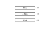
- FIG. 2 is an explanatory diagram illustrating main steps included in an example of the manufacturing method.
- the manufacturing method includes a carbonization step S1, a metal impregnation step S2, and a heat treatment step S3.
- a raw material containing an organic compound as a carbon source, a metal, and a conductive carbon material is carbonized to obtain a carbonized material.
- the organic compound contained in the raw material is not particularly limited as long as it can be carbonized, and any one type or two or more types can be used. That is, as the organic compound, one or both of a high molecular weight organic compound (for example, a resin such as a thermoplastic resin or a thermosetting resin) and a low molecular weight organic compound can be used, and biomass can also be used. it can.
- an organic compound containing nitrogen can be preferably used as the organic compound.
- the organic compound containing nitrogen is not particularly limited as long as it contains a nitrogen atom in the molecule, and any one or more of them can be used.
- a ligand capable of coordinating with a metal can be preferably used. That is, in this case, an organic compound containing one or more coordination atoms in the molecule is used. More specifically, for example, as a coordination atom, an organic compound containing one or more selected from the group consisting of a nitrogen atom, a phosphorus atom, an oxygen atom, and a sulfur atom in the molecule can be used. . Further, for example, an organic compound containing one or more selected from the group consisting of an amino group, a phosphino group, a carboxyl group, and a thiol group in the molecule can also be used as a coordination group.
- organic compounds include, for example, pyrrole, vinylpyridine, imidazole, 2-methylimidazole, aniline, polysulfone, polyaminobismaleimide, polyimide, polyvinyl alcohol, polybenzimidazole, polyamide, polyether, Polyether-terketone, cellulose, lignin, chitin, chitosan, silk, hair, polyamino acid, nucleic acid, DNA, RNA, hydrazine, hydrazide, urea, ionomer, polyacrylic acid, polyacrylic acid ester, polymethacrylic acid ester
- One or more selected from the group consisting of polymethacrylic acid, phenol resin, melamine resin, epoxy resin, furan resin, polyamideimide resin, and polyacrylonitrile can be used.
- the organic compound may further contain, for example, one or more selected from the group consisting of boron, phosphorus, oxygen, and sulfur as a component that improves the activity of the carbon catalyst produced by the production method. .
- the metal contained in the raw material is not particularly limited as long as it does not inhibit the activity of the carbon catalyst produced by this production method, and any one or more kinds can be used.
- This metal can be, for example, one or more selected from the group consisting of Groups 3 to 16 of the periodic table.
- Group 3A Group 3) element, Group 4A (Group 4) element, Group 5A (Group 5) element, Group 6A (Group 6) element, Group 7A (Group 7) element, Group 8 (Group 8) , Group 9 and 10) element, Group 1B (Group 11) element, Group 2B (Group 12) element, Group 3B (Group 13) element, Group 4B (Group 14) element, Group 5B (Group 15) element and 6B 1 type (s) or 2 or more types selected from the group which consists of a group (group 16) element can be used.
- transition metals Group 3 to Group 12 of the periodic table
- transition metal a metal belonging to Group 4 to Group 4 of the periodic table can be preferably used.
- the metal can be used as a simple substance of the metal or a compound of the metal.
- the metal compound for example, metal salts, metal oxides, metal hydroxides, metal nitrides, metal sulfides, metal carbonides, metal complexes can be used, and metal salts, metal oxides, metal sulfides can be used.
- a metal complex can be preferably used.
- a metal complex is formed in the raw material.
- the conductive carbon material contained in the raw material is not particularly limited as long as it imparts conductivity to the carbon catalyst produced by the present production method or improves the conductivity of the carbon catalyst, and any one or two of them can be used.
- the above can be used. That is, as the conductive carbon material, for example, a carbon material having conductivity and having no catalytic activity by itself can be used.
- one or more selected from the group consisting of carbon black, carbon nanotube, carbon nanohorn, carbon fiber, carbon fibril, and graphite powder can be used.
- the conductive carbon material a material in which the above-mentioned metal contained in the raw material is supported in advance can be used. That is, in this case, for example, a conductive carbon material carrying a transition metal that improves the activity and oxidation resistance performance of the carbon catalyst can be used. Transition metals include, for example, scandium, titanium, vanadium, chromium, manganese, iron, cobalt, nickel, copper, zinc, yttrium, zirconium, niobium, molybdenum, ruthenium, rhodium, palladium, lanthanoids (cerium, etc.) and actinides. 1 type (s) or 2 or more types selected from a group can be used.
- the raw material containing the above organic compounds, a metal, and a conductive carbon material is mixed prior to carbonization.
- the method for mixing the raw materials is not particularly limited, and for example, a mortar or a stirring device can be used.
- 1 type, or 2 or more types of mixing methods such as powder mixing which mixes an organic compound, a metal, and an electroconductive carbon material in powder form, and solvent mixing which adds and mixes a solvent, can also be used.
- the raw material prepared as mentioned above is carbonized. That is, the raw material is heated and held at a predetermined temperature (carbonization temperature) at which the raw material can be carbonized.
- the carbonization temperature is not particularly limited as long as the raw material can be carbonized, and can be, for example, 300 ° C. or higher. More specifically, the carbonization temperature can be, for example, 300 ° C. or higher and 1500 ° C. or lower, preferably 400 ° C. or higher and 1200 ° C. or lower, more preferably 500 ° C. or higher and 1100 ° C. or lower. It can be.
- the heating rate at the time of heating the raw material to the carbonization temperature is not particularly limited, and can be, for example, 0.5 ° C./min or more and 300 ° C./min or less.
- the time for holding the raw material at the carbonization temperature is not particularly limited as long as the raw material can be carbonized, and can be, for example, 5 minutes or longer. More specifically, the carbonization time can be, for example, 5 minutes or more and 240 minutes or less, preferably 20 minutes or more and 180 minutes or less.
- Carbonization is preferably performed under an inert gas such as nitrogen (for example, under the flow of an inert gas).
- a carbonized material generated by carbonization of the raw material is obtained.
- the obtained carbonized material can also be pulverized.
- the method for pulverizing the carbonized material is not particularly limited, and for example, a pulverizing apparatus such as a ball mill or a bead mill can be used.
- the average particle size of the carbonized material after pulverization can be, for example, 150 ⁇ m or less, and preferably 45 ⁇ m or less.
- nitrogen atoms can be introduced (doped) into the obtained carbonized material.
- a method for introducing nitrogen atoms for example, a vapor phase doping method such as an ammoxidation method or a CVD method, a liquid phase doping method, or a gas phase-liquid phase doping method can be used.
- a nitrogen source such as ammonia, melamine, or acetonitrile is mixed with a carbonized material, and the resulting mixture is heated to a temperature of 550 ° C. or higher and 1200 ° C. or lower in an inert gas atmosphere such as nitrogen, argon, or helium.
- nitrogen atoms can be introduced into the surface of the carbonized material.
- activation treatment such as steam activation, carbon dioxide activation, phosphoric acid activation, alkali activation, hydrogen activation, ammonia activation, nitric oxide activation, electrolytic activation, and / or nitric acid oxidation, mixed acid oxidation, Liquid phase oxidation such as hydrogen peroxide oxidation can also be performed.
- the carbonized material obtained in the carbonization step S1 is impregnated with metal.
- the metal impregnated in the carbonized material is not particularly limited as long as it does not inhibit the activity of the carbon catalyst produced by the production method, and any one or more kinds can be used.
- the metal can be, for example, one or more selected from the group consisting of groups 3 to 16 of the periodic table.
- a metal a transition metal (Group 3 to Group 12 of the periodic table) can be preferably used, for example.
- a metal belonging to the fourth period, the fifth period, or the sixth period of Groups 3 to 12 of the periodic table can be preferably used.
- one or more selected from the group consisting of titanium, chromium, manganese, iron, cobalt, nickel, copper, zinc, zirconium, niobium, molybdenum, ruthenium, lanthanum, cerium, and tantalum are preferable.
- One or two or more selected from the group consisting of titanium, iron, zirconium, ruthenium and cerium can be used more preferably.
- the carbonized material can be impregnated with a different type of metal from the metal contained in the raw material used in the carbonization step S1 described above. That is, for example, aluminum, silicon, titanium, chromium, manganese, iron, cobalt, nickel, copper, zinc, gallium, zirconium, niobium, molybdenum, ruthenium, indium, tin, lanthanum, cerium, tantalum, lead, or titanium
- the carbonized material can be impregnated with one or more selected from the group consisting of iron, zirconium, ruthenium and cerium, and different from the metal contained in the raw material.
- the metal can be used as a simple substance of the metal or a compound of the metal.
- the metal compound for example, metal salts, metal oxides, metal hydroxides, metal nitrides, metal sulfides, metal carbonides, metal complexes can be used, and metal salts, metal oxides, metal sulfides can be used.
- a metal complex can be preferably used.
- the method of impregnating the carbonized material with the metal in the metal impregnation step S2 is not particularly limited as long as at least the surface of the carbonized material can be impregnated with the metal.
- the carbonized material is added to the metal A method of contacting with a solution containing can be used.
- the carbonized material can be impregnated with the metal.
- the carbonized material can be retained in the boiled metal-containing solution.
- an acidic solution can also be used as a metal containing solution.
- the pH of the metal-containing solution can be set to 1 or more and 6 or less, for example.
- the carbonized material impregnated with the metal in the metal impregnation step S2 is subjected to heat treatment.
- the heat treatment is performed by holding the carbonized material at a predetermined temperature (heat treatment temperature).
- the carbonized material is heated at 300 ° C. or higher.
- This heat treatment temperature may be 400 ° C. or higher, for example. More specifically, the heat treatment temperature can be, for example, 300 ° C. or more and 1500 ° C. or less, preferably 400 ° C. or more and 1400 ° C. or less, more preferably 500 ° C. or more and 1300 ° C. or less. can do.
- the heat treatment temperature can be the same temperature as the carbonization temperature described above, or can be a different temperature. That is, the heat treatment temperature can be set to a temperature equal to or lower than the carbonization temperature of the raw material in the carbonization step S1, for example, and can be set to a temperature lower than the carbonization temperature. Further, the heat treatment temperature can be higher than the carbonization temperature.
- the heat treatment temperature is 300 ° C. or more and 1000 ° C. or less and the carbonization temperature or less or The temperature can be lower than the carbonization temperature.
- the heating rate when heating the carbonized material to the heat treatment temperature is not particularly limited, and can be, for example, 0.5 ° C./min or more and 300 ° C./min or less.
- the time for holding the carbonized material at the heat treatment temperature is not particularly limited as long as the effect of the heat treatment can be obtained, and can be, for example, 5 minutes or more. More specifically, the heat treatment time can be, for example, 5 minutes or more and 240 minutes or less, preferably 20 minutes or more and 180 minutes or less.
- the heat treatment is preferably performed under an inert gas such as nitrogen (for example, under the flow of an inert gas).
- a carbonized material that has been heat-treated after metal impregnation is obtained.
- the obtained carbonized material can also be pulverized.
- the method for pulverizing the carbonized material is not particularly limited, and for example, a pulverizing apparatus such as a ball mill or a bead mill can be used.
- the average particle diameter of the carbonized material after pulverization can be, for example, 150 ⁇ m or less, and preferably 45 ⁇ m or less.
- the carbonized material obtained in this heat treatment step S3 can be obtained as a carbon catalyst.
- this production method including the carbonization step S1, the metal impregnation step S2, and the heat treatment step S3, it is possible to produce a carbon catalyst having improved activity as compared with the conventional method. That is, this manufacturing method can enhance the activity of the carbon catalyst effectively by including the metal impregnation step S2 and the heat treatment step S3 described above.
- a carbonized material having catalytic activity can be obtained in the carbonization step S1, and the catalytic activity can be remarkably increased by subjecting the carbonized material to metal impregnation treatment and heat treatment. it can.
- a new carbon structure different from the carbon structure formed by carbonization may be formed by the metal impregnation treatment and the heat treatment.
- the metal contained in the raw material can be dispersed and arranged on the entire surface and inside of the carbonized material, whereas the metal impregnated in the carbonized material in the metal impregnation step S2 mainly It is locally disposed on the surface of the carbonized material and in the vicinity thereof.
- the metal impregnation treatment and the heat treatment have a side surface treatment for the carbonized material. Also from this point, it is considered that the carbon structure formed by metal impregnation treatment and heat treatment is different from the carbon structure formed by carbonization.
- a treatment for removing the metal contained in the carbonized material can be performed as necessary (for example, when the metal is not required after carbonization).
- the present manufacturing method includes a metal removal step of performing a metal removal process on the carbonized material that has been subjected to the heat treatment in the above-described heat treatment step S3, and a step after the metal removal of performing a heat treatment on the carbonized material that has been subjected to the metal removal process. And a heat treatment step.
- the metal removal treatment is not particularly limited as long as it can remove the metal contained in the carbonized material or reduce the amount of the metal, and for example, an acid cleaning treatment or an electrolytic treatment can be performed.
- the acid used for the acid cleaning is not particularly limited as long as the effect of the metal removal treatment can be obtained, and any one kind or two or more kinds can be used. That is, for example, one or more selected from the group consisting of hydrochloric acid (for example, concentrated hydrochloric acid), nitric acid (for example, concentrated nitric acid), and sulfuric acid (for example, concentrated sulfuric acid) can be used.
- hydrochloric acid for example, concentrated hydrochloric acid
- nitric acid for example, concentrated nitric acid
- sulfuric acid for example, concentrated sulfuric acid
- a mixed acid prepared by mixing concentrated hydrochloric acid and concentrated nitric acid at a predetermined volume ratio for example, aqua regia
- concentrated nitric acid and concentrated sulfuric acid A mixed acid prepared by mixing at a volume ratio can be used.
- the acid cleaning method is not particularly limited as long as the effect of the metal removal treatment can be obtained.
- a method of immersing and holding the carbonized material in an acid-containing solution can be used.
- the carbonized material can be held in a boiled acid solution.
- the same heat treatment as in the heat treatment step S3 described above is performed.
- a carbonized material that has been heat treated after metal removal is obtained.
- the obtained carbonized material can also be pulverized in the same manner as the carbonized material subjected to the heat treatment in the heat treatment step S3 described above.
- the carbonization material obtained by this heat treatment process after metal removal can be obtained as a carbon catalyst.
- a carbon catalyst with improved activity can be produced. That is, in this case, for example, the activity of the carbon catalyst can be effectively enhanced by removing the metal component from the carbonized material and exposing the active sites.
- the metal impregnation process can be performed in the metal impregnation process S2 without performing the above-described metal removal process on the carbonized material obtained in the carbonization process S1. That is, in this case, in the metal impregnation step S2, the carbonized material is impregnated with the metal without removing the metal contained in the raw material from the carbonized material. Moreover, after performing a metal removal process on the carbonized material, a metal impregnation process can also be performed. That is, in this case, in the metal impregnation step S2, the carbonized material from which the metal contained in the raw material has been removed is impregnated with the metal.
- the present manufacturing method includes an additional metal impregnation step in which a metal is further impregnated into the carbonized material subjected to the heat treatment in the above-described heat treatment step S3, and a heat treatment is performed on the carbonized material impregnated with the metal in the additional metal impregnation step.
- an additional heat treatment step of applying includes, for example, a carbonization step S1, a metal impregnation step S2, a heat treatment step S3, an additional metal impregnation step, and an additional heat treatment step.
- the metal impregnated into the carbonized material in the additional metal impregnation step is not particularly limited as long as it does not inhibit the activity of the carbon catalyst produced by the present production method, and any one kind or two or more kinds can be used. .
- the metal can be, for example, one or more selected from the group consisting of groups 3 to 16 of the periodic table.
- a metal a transition metal (Group 3 to Group 12 of the periodic table) can be preferably used, for example.
- a metal belonging to the fourth period, the fifth period, or the sixth period of Groups 3 to 12 of the periodic table can be particularly preferably used.
- one or more selected from the group consisting of titanium, chromium, manganese, iron, cobalt, nickel, copper, zinc, zirconium, niobium, molybdenum, ruthenium, lanthanum, cerium, and tantalum are preferable.
- One or two or more selected from the group consisting of titanium, iron, zirconium, ruthenium and cerium can be used more preferably.
- the carbonized material can be impregnated with a metal different from the metal contained in the raw material used in the carbonization step S1 described above. That is, for example, aluminum, silicon, titanium, chromium, manganese, iron, cobalt, nickel, copper, zinc, gallium, zirconium, niobium, molybdenum, ruthenium, indium, tin, lanthanum, cerium, tantalum, lead, or titanium
- the carbonized material can be impregnated with one or more selected from the group consisting of iron, zirconium, ruthenium and cerium, and different from the metal contained in the raw material.
- the carbonized material can be impregnated with a different type of metal from the metal impregnated in the metal impregnation step S2. That is, for example, the group consisting of aluminum, silicon, titanium, chromium, manganese, iron, cobalt, nickel, copper, zinc, gallium, zirconium, niobium, molybdenum, ruthenium, indium, tin, lanthanum, cerium, tantalum, lead, or titanium
- the carbonized material can be impregnated with one or more selected from the group consisting of iron, zirconium, ruthenium, and cerium, and different from the metal impregnated with the carbonized material in the metal impregnation step S2.
- the carbonized material in the additional metal impregnation step, can be impregnated with a metal that is different from the metal impregnated in the metal impregnation step S2 and can take tetravalence. That is, in this case, for example, the carbonized material can be impregnated with a divalent or trivalent metal in the metal impregnation step S2, and the carbonized material can be impregnated with a tetravalent metal in the additional metal impregnation step.
- the metal can be used as a simple substance of the metal or a compound of the metal.
- the metal compound for example, metal salts, metal oxides, metal hydroxides, metal nitrides, metal sulfides, metal carbonides, metal complexes can be used, and metal salts, metal oxides, metal sulfides can be used.
- a metal complex can be preferably used.
- the method of impregnating the carbonized material with the metal in the additional metal impregnation step is not particularly limited as long as at least the surface of the carbonized material can be impregnated with the metal.
- the carbonized material may be impregnated with the metal.
- a method of contacting a solution containing a carbonized material can be used.
- the carbonized material can be impregnated with the metal.
- the carbonized material can be retained in the boiled metal-containing solution.
- an acidic solution can also be used as a metal containing solution.
- the pH of the metal-containing solution can be set to 1 or more and 6 or less, for example.
- the heat treatment temperature in the additional heat treatment step can be the same temperature as the heat treatment temperature in the heat treatment step S3 described above, or can be a different temperature.
- the additional heat treatment step a carbonized material that has been heat-treated after the additional metal impregnation treatment is obtained.
- the obtained carbonized material can also be pulverized in the same manner as the carbonized material subjected to the heat treatment in the heat treatment step S3 described above.
- the above-mentioned additional metal impregnation process and additional heat treatment process can also be repeated twice or more.
- the carbonization material obtained by this additional heat treatment process can be obtained as a carbon catalyst.
- additional metal impregnation treatment and additional heat treatment it is possible to produce a carbon catalyst with improved activity. That is, in this case, for example, the activity of the carbon catalyst can be effectively increased by forming a new carbon structure.
- the production method may further include the above-described additional metal impregnation step and additional heat treatment step, and the above-described metal removal step and post-metal removal heat treatment step. That is, this manufacturing method includes, for example, a carbonization step S1, a metal impregnation step S2, a heat treatment step S3, a metal removal step, a post-metal removal heat treatment step, an additional metal impregnation step, and an additional heat treatment step.
- the carbonized material subjected to the metal removal treatment and the heat treatment after metal removal is impregnated with the metal again.
- the carbonized material after the heat treatment in each additional heat treatment step can be subjected to metal removal treatment and heat treatment after metal removal.
- the present manufacturing method includes an acid treatment step in which the carbonized material subjected to the heat treatment in the above-described heat treatment step S3 is subjected to an acid treatment, and a post-acid treatment heat treatment in which the carbonized material subjected to the acid treatment is subjected to a heat treatment.
- this manufacturing method includes, for example, a carbonization step S1, a metal impregnation step S2, a heat treatment step S3, an acid treatment step, and a post-acid treatment heat treatment step.
- the acid used for the acid treatment is not particularly limited as long as the effect of the acid treatment can be obtained, and any one kind or two or more kinds can be used. That is, for example, one or more selected from the group consisting of hydrochloric acid (for example, concentrated hydrochloric acid), nitric acid (for example, concentrated nitric acid), and sulfuric acid (for example, concentrated sulfuric acid) can be used.
- hydrochloric acid for example, concentrated hydrochloric acid
- nitric acid for example, concentrated nitric acid
- sulfuric acid for example, concentrated sulfuric acid
- a mixed acid prepared by mixing concentrated hydrochloric acid and concentrated nitric acid at a predetermined volume ratio for example, aqua regia
- concentrated nitric acid and concentrated sulfuric acid A mixed acid prepared by mixing at a volume ratio can be used.
- the acid treatment method is not particularly limited as long as the effect of the acid treatment can be obtained.
- a method of immersing and holding the carbonized material in an acid-containing solution can be used.
- the carbonized material can be held in a boiled acid solution.
- an acid treatment can also be performed on the carbonized material by acid cleaning the carbonized material in the above-described metal removing step. That is, the acid cleaning for removing the metal can be an embodiment of the acid treatment as the surface treatment.
- the same heat treatment as in the heat treatment step S3 described above is performed.
- a carbonized material that has been heat-treated after acid treatment is obtained.
- the obtained carbonized material can also be pulverized in the same manner as the carbonized material subjected to the heat treatment in the heat treatment step S3 described above.
- the above-mentioned acid treatment process and post-acid treatment heat treatment process can also be repeated twice or more.
- the carbonized material obtained in the heat treatment step after the acid treatment can be obtained as a carbon catalyst.
- a carbon catalyst with improved activity can be produced. That is, in this case, for example, by introducing a new functional group on the surface of the carbonized material and in the vicinity thereof, the activity of the carbon catalyst can be effectively enhanced.
- this manufacturing method can further include the above-described acid treatment step and post-acid treatment heat treatment step, and the above-described metal removal step and post-metal removal heat treatment step. That is, this manufacturing method includes, for example, a carbonization step S1, a metal impregnation step S2, a heat treatment step S3, a metal removal step, a heat treatment step after metal removal, an acid treatment step, and a heat treatment step after acid treatment.
- the carbonized material subjected to the metal removal treatment and the heat treatment after metal removal is subjected to acid treatment.
- the acid treatment step and the heat treatment step after acid treatment are repeated twice or more, the carbonized material after the heat treatment in each post-acid treatment heat treatment step can be subjected to metal removal treatment and heat treatment after metal removal.
- the present catalyst was obtained, for example, by impregnating a carbonized material obtained by carbonization of a raw material containing an organic compound as a carbon source, a metal, and a conductive carbon material, and further performing a heat treatment. It can be a carbon catalyst.
- the catalyst can be preferably produced by the production method described above. That is, the present catalyst can be, for example, a carbon catalyst manufactured by the present manufacturing method including the above-described carbonization step S1, metal impregnation step S2, and heat treatment step S3. In this case, the present catalyst can also be a carbon catalyst having a carbon structure in which desorption of carbon monoxide and carbon dioxide as described above occurs in the temperature programmed desorption method.
- Example 1-1 Production of carbon catalyst PCoFe for hydrogen peroxide decomposition
- the raw material used as the object of carbonization was prepared. That is, 1.5 g of polyacrylonitrile-polymethacrylic acid copolymer (PAN / PMA) was dissolved in 30 mL of dimethylformamide, then 1.5 g of 2-methylimidazole and 1.5 g of cobalt chloride hexahydrate. The product (CoCl 2 ⁇ 6H 2 O) was added and stirred at room temperature for 2 hours. To the mixture thus obtained, ketjen black (ECP600JD, manufactured by Lion Corporation) was added so as to be 30% by weight of the solid content contained in the raw material, and mixed using a mortar. The resulting mixture was vacuum dried at 60 ° C. for 12 hours.
- PAN / PMA polyacrylonitrile-polymethacrylic acid copolymer
- 2-methylimidazole 1.5 g
- cobalt chloride hexahydrate The product (CoCl 2
- this mixture was heated in the air, and the temperature was raised from room temperature to 150 ° C. over 30 minutes, and then the temperature was raised from 150 ° C. to 220 ° C. over 2 hours. Thereafter, the mixture was held at 220 ° C. for 3 hours to infusibilize the mixture.
- the raw material for the carbonized material was prepared.
- the material was carbonized. Specifically, the infusibilized raw material as described above was placed in a quartz tube, purged with nitrogen for 20 minutes in an image furnace, and heated from room temperature to 900 ° C. over 18 minutes. Thereafter, this raw material was held at 900 ° C. for 1 hour to perform carbonization. Thus, a carbonized material was obtained.
- this carbonized material was pulverized. That is, 10 cycles of zirconia balls having a diameter of 10 mm were set in a planetary ball mill (P-7, manufactured by Fritsch Japan Co., Ltd.), and the carbonized material was pulverized for 5 minutes at a rotational speed of 650 rpm by the planetary ball mill for 10 cycles. Thereafter, the pulverized carbonized material was taken out, and a carbonized material that passed through a sieve having an aperture of 106 ⁇ m was obtained as a pulverized fine particle carbonized material.
- P-7 planetary ball mill
- metal impregnation treatment was performed. That is, a solution prepared by adding 2 g of iron (III) chloride hexahydrate (FeCl 3 .6H 2 O) to 300 mL of distilled water was boiled, and 2 g of the above carbonized material was added to the iron-containing solution. . Then, the carbonized material was impregnated with iron for 3 hours while stirring in the boiling iron-containing solution. Thereafter, the solution containing the carbonized material was filtered using a filtration membrane (pore size: 1.0 ⁇ m, manufactured by Millipore), and washed with distilled water until the filtrate became neutral. The collected carbonized material was vacuum-dried at 60 ° C. for 12 hours. Furthermore, the dried carbonized material was pulverized in a mortar.
- iron (III) chloride hexahydrate FeCl 3 .6H 2 O
- the carbonized material after the heat treatment was pulverized. That is, a process in which a zirconia ball having a diameter of 10 mm was set in a planetary ball mill and the carbonized material was pulverized by the planetary ball mill at a rotational speed of 450 rpm for 5 minutes was performed. Thereafter, the pulverized carbonized material was taken out, and a carbonized material that passed through a sieve having an aperture of 106 ⁇ m was obtained as a pulverized particulate hydrogen peroxide decomposition carbon catalyst (PCoFe).
- PCoFe pulverized particulate hydrogen peroxide decomposition carbon catalyst
- Example 1-2 Production of carbon catalyst PCoFeAW for hydrogen peroxide decomposition
- the carbon catalyst for decomposition of hydrogen peroxide (PCoFe) obtained in Example 1-1 was subjected to metal removal treatment by acid cleaning.
- heat treatment was performed after removing the metal. That is, the carbon catalyst subjected to the metal removal treatment as described above was placed in a quartz tube, purged with nitrogen for 20 minutes in an image furnace, and heated from room temperature to 700 ° C. over 14 minutes. Thereafter, the carbon catalyst was held at 700 ° C. for 1 hour.
- the carbon catalyst after this heat treatment was pulverized. That is, a process in which a zirconia ball having a diameter of 10 mm was set in a planetary ball mill and the carbonized material was pulverized by the planetary ball mill at a rotational speed of 450 rpm for 5 minutes was performed. Thereafter, the pulverized carbonized material was taken out, and a carbonized material that passed through a sieve having an aperture of 106 ⁇ m was obtained as a pulverized particulate hydrogen peroxide decomposition carbon catalyst (PCoFeAW).
- PCoFeAW pulverized particulate hydrogen peroxide decomposition carbon catalyst
- Example 1-3 Production of carbon catalyst CoFeAW for hydrogen peroxide decomposition
- a carbon catalyst (CoFeAW) was produced in the same manner as in Example 1-2, except that the following raw material not containing PAN / PMA was used as the raw material for the carbonized material.
- Example 1-4 Production of carbon catalyst PCoFeAWZr for hydrogen peroxide decomposition
- the carbon catalyst for decomposition of hydrogen peroxide (PCoFeAW) obtained in Example 1-2 described above was subjected to additional metal impregnation treatment.
- a solution prepared by adding 2 g of zirconium chloride oxide octahydrate (ZrCl 2 O ⁇ 8H 2 O) to 300 mL of distilled water was boiled, and 2 g of carbon catalyst (PCoFeAW) was added to the zirconium-containing solution. Then, the carbon catalyst was impregnated with zirconium for 3 hours while stirring in the boiling zirconium-containing solution. Thereafter, the solution containing the carbon catalyst was filtered using a filtration membrane (pore size: 1.0 ⁇ m, manufactured by Millipore), and washed with distilled water until the filtrate became neutral. The collected carbon catalyst was vacuum-dried at 60 ° C. for 12 hours. Furthermore, the dried carbon catalyst was pulverized in a mortar.
- PCoFeAW carbon catalyst
- the carbon catalyst after this heat treatment was pulverized. That is, a process in which a zirconia ball having a diameter of 1.5 mm was set in a planetary ball mill and the carbon catalyst was pulverized for 5 minutes at a rotational speed of 450 rpm by the planetary ball mill was performed for 4 cycles. Thereafter, the pulverized carbon catalyst was taken out, and a carbon catalyst that passed through a sieve having an aperture of 106 ⁇ m was obtained as a pulverized particulate hydrogen peroxide decomposition carbon catalyst (PCoFeAWZr).
- PCoFeAWZr pulverized particulate hydrogen peroxide decomposition carbon catalyst
- Example 1-5 Production of carbon catalyst PCoFeAWHNO 3 for hydrogen peroxide decomposition
- the carbon catalyst for decomposition of hydrogen peroxide (PCoFeAW) obtained in the above Example 1-2 was subjected to acid treatment.
- the carbon catalyst after this heat treatment was pulverized. That is, a process in which a zirconia ball having a diameter of 10 mm was set in a planetary ball mill and the carbon catalyst was pulverized for 5 minutes at a rotational speed of 450 rpm by the planetary ball mill was performed for 4 cycles. Thereafter, the pulverized carbon catalyst was taken out, and a carbon catalyst that passed through a sieve having an aperture of 106 ⁇ m was obtained as a pulverized particulate hydrogen peroxide decomposition carbon catalyst (PCoFeAWHNO 3 ).
- PCoFeAWHNO 3 pulverized particulate hydrogen peroxide decomposition carbon catalyst
- Ketjen Black (ECP600JD, Lion Corporation), which is a conductive carbon material, was prepared as a carbonized material according to Comparative Example 1-3.
- pretreatment of the carbon catalyst desorption of catalyst surface functional groups by heat treatment
- 0.02 g of a carbon catalyst was filled in the center of a quartz reaction tube and set in a temperature programmed desorption apparatus.
- the inside of the apparatus was heated to 50 ° C. at a temperature rising rate of 5 ° C./min and held for 40 minutes to stabilize the apparatus.
- the carbon catalyst was heated and heated to 900 ° C. at a temperature rising rate of 10 ° C./min, whereby the carbon catalyst was heat-treated to desorb functional groups on the surface.
- oxygen was adsorbed on the surface of the carbon catalyst. That is, the apparatus was first stabilized by holding the inside of the apparatus at 150 ° C. for 10 minutes. Thereafter, oxygen (O 2 ) gas is circulated through the carbon catalyst that has been heat-treated as described above so as to be 5% by volume, and is held at 150 ° C. for 20 minutes, whereby the surface of the carbon catalyst (mainly the edge) Oxygen was chemisorbed on the surface.
- the carbon catalyst was subjected to a heat treatment, and desorbed carbon monoxide (CO) and carbon dioxide (CO 2 ) were measured. That is, helium (He) gas was flowed into the apparatus at 150 ° C. for 25 minutes to degas oxygen that was not chemically adsorbed. Next, the temperature inside the apparatus was again increased from 150 ° C. to 900 ° C. at a temperature increase rate of 10 ° C./min. During this temperature increase, helium (He) gas was circulated at 50 mL / min, and carbon monoxide and carbon dioxide generated by desorption of oxygen-containing compounds were detected. Temperature (horizontal axis) and detected intensity (vertical axis) The correlation of was recorded.
- helium (He) gas was flowed into the apparatus at 150 ° C. for 25 minutes to degas oxygen that was not chemically adsorbed.
- the temperature inside the apparatus was again increased from 150 ° C. to 900 ° C. at a temperature increase rate of 10 ° C
- the amounts of carbon monoxide and carbon dioxide desorbed were determined. That is, the integrated values (detected intensity areas) of the detected intensities of carbon monoxide and carbon dioxide from 150 ° C. at which heat treatment was started to the temperature (400 ° C. or 900 ° C.) to be quantified were calculated. On the other hand, by using a predetermined amount of calcium oxalate monohydrate (CaC 2 O 4 ⁇ H 2 O) as a reference substance, and the desorption amount of carbon monoxide and carbon dioxide, and the detection intensity area, the correlation between the The calibration curve shown was created.
- a predetermined amount of calcium oxalate monohydrate CaC 2 O 4 ⁇ H 2 O
- FIG. 3 shows the results of evaluating the amount of carbon monoxide and carbon dioxide desorbed from 150 ° C. to 400 ° C. or 900 ° C. in the temperature programmed desorption method for each carbon catalyst.
- the desorption amount of the hydrogen peroxide decomposition carbon catalysts subjected to the metal impregnation treatment is the same as that of the carbon catalyst not subjected to the metal impregnation treatment (Comparative Example). It was significantly larger than that of 1-1) and the conductive carbon material (Comparative Example 1-3). That is, the amount of carbon monoxide and carbon dioxide desorbed in the temperature-programmed desorption method significantly increased by the metal impregnation treatment.
- decomposition rate (%) ⁇ hydrogen peroxide concentration before treatment (mg / L) ⁇ hydrogen peroxide concentration after treatment (mg / L) ⁇ / Hydrogen peroxide concentration before treatment (mg / L) ⁇ 100 ”.
- FIG. 4 shows the results of evaluating the hydrogen peroxide decomposition catalytic ability of each catalyst in this way.
- a carbon catalyst for decomposing hydrogen peroxide Examples 2-2 to 4
- the manganese dioxide catalyst according to Comparative Example 2-1 and the carbon catalyst according to Comparative Example 2-2 were used.
- a high hydrogen peroxide decomposition rate was achieved compared to the case of using. That is, it was confirmed that the hydrogen peroxide decomposition carbon catalysts used in Examples 2-2 to 4 have significantly higher hydrogen peroxide decomposition catalytic activity than the catalysts used in Comparative Examples 2-1 and 2. It was.
- a polyvinyl butyral 1000 (PVB: degree of polymerization 900-1100, manufactured by Wako Pure Chemical Industries, Ltd.), a water-insoluble polymer, dissolved in methanol to a concentration of 10% by weight, and a water-soluble polymer poly
- a catalyst slurry (coating catalyst composition for coating) was prepared by adding the carbon catalyst for hydrogen peroxide decomposition (PCoFeAW) produced in Example 1-2 described above to this polymer binder solution so as to be 50% by weight. ) was prepared. The catalyst slurry was applied to the surface of a substrate having a surface area of 1 cm 2 and dried to prepare a molded body composed of a catalyst and a polymer binder.
- PCoFeAW carbon catalyst for hydrogen peroxide decomposition
- this molded body was immersed in water to elute polyacrylic acid from the molded body.
- a film-like catalyst molded article for hydrogen peroxide decomposition having a porous structure formed by removing polyacrylic acid was obtained.
- manganese dioxide-containing catalyst compact In place of the carbon catalyst for decomposing hydrogen peroxide, manganese dioxide (FMV, manufactured by Tosoh Corporation) (MnO 2 ) was used, except that polyacrylic acid was used in the same manner as the above-mentioned catalyst molded product for decomposing hydrogen peroxide. A film-like manganese dioxide-containing catalyst molded body having a porous structure formed by removal was obtained.
- the hydrogen peroxide aqueous solution was treated in the same manner except that the manganese dioxide-containing catalyst molded body obtained as described above was used. The rate was 14%.
- the catalyst molded body containing the carbon catalyst for hydrogen peroxide decomposition has a higher hydrogen peroxide decomposition catalytic activity than the catalyst molded body containing manganese dioxide.
- Example 4-1 Water treatment 1 with carbon catalyst for hydrogen peroxide decomposition
- waste water having a pH of 6.5 to 7.5 was prepared.
- the filtrate obtained by filtering the raw water to remove suspended substances had CODMn of 53 mg / L, CODCr of 99 mg / L, TOC of 54 mg / L, and chromaticity of 391. Further, the BOD of the filtrate obtained by centrifuging the raw water at 10,000 rpm for 10 minutes to remove suspended substances was 40 mg / L.
- CODMn was measured by a method based on JIS K 0102-17
- CODCr was measured by a method based on JIS K 0102-20
- TOC is measured by a method based on the TOC (medium concentration) measurement method of management number 10173 using a water quality analyzer (DR2400) manufactured by HACH, and chromaticity is controlled by the water quality analyzer. It was measured by a method based on 8025 chromaticity measurement method (Platimun-Cobalt Standard Method method).
- raw water was treated with a carbon catalyst for hydrogen peroxide decomposition. That is, first, 200 mL of raw water was put into a 500 mL capacity container. To this raw water, the hydrogen peroxide-decomposing carbon catalyst PCoFeAW produced in Example 1-2 was added to a concentration of 400 mg / L. Furthermore, 2 mL of hydrogen peroxide solution adjusted in advance so that the concentration in the raw water was 100 mg / L was added.
- the raw water containing the carbon catalyst and hydrogen peroxide was shaken at room temperature (27 ° C.) for 15 minutes. After shaking, the treatment liquid was filtered with a filter having a pore diameter of 0.45 ⁇ m to separate the carbon catalyst. The obtained filtrate was measured for CODMn, CODCr, TOC and chromaticity.
- Example 4-2 Water treatment 2 using carbon catalyst for decomposition of hydrogen peroxide
- the raw water was treated with the hydrogen peroxide decomposition carbon catalyst PCoFeAW in the same manner as in Example 4-1 except that hydrogen peroxide water adjusted in advance so that the concentration in the raw water was 500 mg / L was added. did.
- Example 4-3 Water treatment 3 using carbon catalyst for decomposition of hydrogen peroxide
- sulfuric acid was added to the raw water in advance, and the pH was adjusted to 3 to 4, in the same manner as in Example 4-2 above.
- Raw water was treated with the catalyst PCoFeAW.
- the raw water containing iron (II) chloride and hydrogen peroxide was shaken at room temperature (27 ° C.) for 15 minutes. After shaking, sodium hydroxide was added to the treatment liquid to precipitate iron as a hydroxide. Next, the precipitate was removed by filtering the treatment liquid with a filter paper (ADVANTEC 5C). The filtrate was further filtered through a filter having a pore size of 0.45 ⁇ m. The obtained filtrate was measured for CODMn, CODCr, TOC and chromaticity.
- Comparative Example 4-2 Water Treatment 2 by Fenton Method
- the raw water was treated by the Fenton method in the same manner as in Comparative Example 4-1, except that hydrogen peroxide solution adjusted in advance so that the concentration in the raw water was 500 mg / L was added.
- the carbon catalyst for hydrogen peroxide decomposition is added to neutral raw water at pH 6.5 to 7.5 without adjusting the pH to the acidic range as in the Fenton method (Comparative Examples 4-1, 2).
- a sufficient water quality improvement could be achieved only by adding together (Examples 4-1, 2).
Landscapes
- Chemical & Material Sciences (AREA)
- Engineering & Computer Science (AREA)
- Organic Chemistry (AREA)
- Materials Engineering (AREA)
- Chemical Kinetics & Catalysis (AREA)
- Nanotechnology (AREA)
- Physics & Mathematics (AREA)
- Environmental & Geological Engineering (AREA)
- Life Sciences & Earth Sciences (AREA)
- Hydrology & Water Resources (AREA)
- Thermal Sciences (AREA)
- Water Supply & Treatment (AREA)
- Composite Materials (AREA)
- Condensed Matter Physics & Semiconductors (AREA)
- General Physics & Mathematics (AREA)
- Crystallography & Structural Chemistry (AREA)
- Inorganic Chemistry (AREA)
- Catalysts (AREA)
- Removal Of Specific Substances (AREA)
- Treatment Of Water By Oxidation Or Reduction (AREA)
Abstract
Description
まず、炭素化の対象となる原料を調製した。すなわち、1.5gのポリアクリロニトリル-ポリメタクリル酸共重合体(PAN/PMA)を30mLのジメチルホルムアミドに溶解させた後、1.5gの2-メチルイミダゾールと、1.5gの塩化コバルト六水和物(CoCl2・6H2O)と、を加え、室温で2時間攪拌した。こうして得られた混合物に、ケッチェンブラック(ECP600JD、ライオン株式会社製)が、原料に含有される固形分の30重量%となるように加え、乳鉢を用いて混合した。得られた混合物を、60℃で12時間、真空乾燥した。
上述の実施例1-1で得られた過酸化水素分解用炭素触媒(PCoFe)に酸洗浄による金属除去処理を施した。
炭素化材料の原料として、PAN/PMAを含まない次の原料を使用した以外は、上述の実施例1-2と同様にして、炭素触媒(CoFeAW)を製造した。
上述の実施例1-2で得られた過酸化水素分解用炭素触媒(PCoFeAW)に追加金属含浸処理を施した。
上述の実施例1-2で得られた過酸化水素分解用炭素触媒(PCoFeAW)に酸処理を施した。
金属含浸処理、熱処理及び当該熱処理後の粉砕処理を行わなかった以外は、上述の実施例1-2と同様にして、比較例1-1に係る触媒として、粉砕された微粒子状の炭素触媒(PCoAW)を得た。
比較例1-2に係る触媒として、二酸化マンガン(FMV、東ソー株式会社製)を準備した。
導電性炭素材料であるケッチェンブラック(ECP600JD、ライオン株式会社)を比較例1-3に係る炭素化材料として準備した。
上述の実施例1-2~5で製造した過酸化水素分解用炭素触媒、比較例1-1で製造した炭素触媒及び比較例1-3で準備したケッチェンブラック(KB)のそれぞれについて、昇温脱離法による評価を行った。すなわち、昇温脱離装置(日本ベル株式会社製)に炭素触媒を設置し、キャリアガス(He)を50mL/分で流通させた高真空下で当該炭素触媒を加熱し、脱離したガスを四重極質量分析計(Quadrupole Mass Spectrometer:QMS)で測定した。
上述の実施例1-2~4で製造した過酸化水素分解用炭素触媒、比較例1-1で製造した炭素触媒及び比較例1-2で準備した二酸化マンガン触媒のいずれか1.5mgを、過酸化水素(H2O2)を3400mg/Lの濃度で含有する水溶液30mLに添加し、スターラーで攪拌しながら室温(27℃)で20分保持した。
非水溶性高分子であるポリビニルブチラール1000(PVB:重合度900-1100、和光純薬工業株式会社製)をメタノールに10重量%となるように溶解したPVB溶液と、水溶性高分子であるポリアクリル酸(PMA:Mw=25000、和光純薬工業株式会社製)をメタノールに10重量%となるように溶解したPMA溶液と、を体積比4:1で混合することにより、高分子バインダー溶液を調製した。
過酸化水素分解用炭素触媒に代えて、二酸化マンガン(FMV、東ソー株式会社製)(MnO2)を使用した以外は、上述の過酸化水素分解用触媒成形体と同様にして、ポリアクリル酸を除去することにより形成された多孔構造を有する、フィルム状の二酸化マンガン含有触媒成形体を得た。
上述のようにして得られた過酸化水素分解用触媒成形体を、過酸化水素を3000mg/Lの濃度で含有する水溶液に浸漬し、室温(27℃)で120分保持した。120分経過後、直ちに過酸化水素水溶液から過酸化水素分解用触媒成形体を取り出した。そして、処理後の水溶液に含有される過酸化水素濃度を過マンガン酸滴定により定量し、上述の実施例1と同様に、過酸化水素の分解率を算出した。その結果、過酸化水素の分解率は36%であった。
処理の対象とする原水として、pHが6.5~7.5の排水を準備した。この原水をろ過して懸濁物質を除去することにより得られたろ液は、CODMnが53mg/L、CODCrが99mg/L、TOCが54mg/L、色度が391であった。また、この原水を10000rpmで10分間遠心分離して懸濁物質を除去することにより得られたろ液のBODは40mg/Lであった。
原水中の濃度が500mg/Lとなるように予め調整した過酸化水素水を添加した以外は、上述の実施例4-1と同様にして、過酸化水素分解用炭素触媒PCoFeAWにより、原水を処理した。
過酸化水素分解用炭素触媒を添加する前に、予め原水に硫酸を添加し、pHを3~4に調整した以外は、上述の実施例4-2と同様にして、過酸化水素分解用炭素触媒PCoFeAWにより、原水を処理した。
フェントン法により、上述の原水を処理した。すなわち、まず、原水に硫酸を添加し、pHを3~4に調整した。この原水200mLを容積500mLの容器に入れた。次いで、この原水に、塩化鉄(II)(FeCl2)を、原水中での濃度が400mg/Lとなるように添加した。さらに、原水中の濃度が100mg/Lとなるように予め調整した過酸化水素水を2mL加えた。
原水中の濃度が500mg/Lとなるように予め調整した過酸化水素水を添加した以外は、上述の比較例4-1と同様にして、フェントン法により、原水を処理した。
炭素触媒に代えて二酸化マンガン(MnO2)を使用した以外は、上述の実施例4-1と同様にして、当該二酸化マンガンにより、原水を処理した。
炭素触媒に代えて酸化コバルト(CoO)を使用した以外は、上述の実施例4-2と同様にして、当該酸化コバルトにより、原水を処理した。
図5には、各例における水質改善触媒活性の評価結果を処理条件とともに示す。なお、図5のCODCr欄に示す「-」は、測定を行わなかったことを示す。
Claims (11)
- 昇温脱離法における150℃から400℃での一酸化炭素の脱離量及び二酸化炭素の脱離量の合計が、0.02gあたり0.06mmol以上である
ことを特徴とする過酸化水素分解用炭素触媒。 - 前記一酸化炭素の脱離量が0.01mmol以上であり、前記二酸化炭素の脱離量が0.05mmol以上である
ことを特徴とする請求項1に記載された過酸化水素分解用炭素触媒。 - 炭素源としての有機化合物、金属及び導電性炭素材料を含む原料の炭素化により得られた炭素化材料に金属を含浸させ、さらに熱処理を施して得られた
ことを特徴とする過酸化水素分解用炭素触媒。 - 溶液中、気体中又はミスト中の過酸化水素を分解するために使用される
ことを特徴とする請求項1乃至3のいずれかに記載された過酸化水素分解用炭素触媒。 - 過酸化水素の存在下で溶液中、気体中又はミスト中の有機物の分解を促進するために使用される
ことを特徴とする請求項1乃至3のいずれかに記載された過酸化水素分解用炭素触媒。 - 請求項1乃至5のいずれかに記載された過酸化水素分解用炭素触媒と、
高分子バインダーと、
を含む
ことを特徴とする過酸化水素分解用触媒成形体。 - 前記高分子バインダーは、水溶性高分子と非水溶性高分子とを含む
ことを特徴とする請求項6に記載された過酸化水素分解用触媒成形体。 - 前記過酸化水素分解用炭素触媒と、水溶性高分子と非水溶性高分子とを含む前記高分子バインダーと、を含有する成形体を水溶液で処理し、前記高分子バインダーに含まれる前記水溶性高分子を前記成形体から除去することにより形成された多孔構造を有する
ことを特徴とする請求項6に記載された過酸化水素分解用触媒成形体。 - 前記水溶性高分子は、ポリアクリル酸、ポリエチレングリコール及びポリビニルアルコールからなる群より選択される1種又は2種以上である
ことを特徴とする請求項7又は8に記載された過酸化水素分解用触媒成形体。 - 請求項1乃至5のいずれかに記載された過酸化水素分解用炭素触媒と、水溶性高分子及び非水溶性高分子を含む高分子バインダーと、を含む
ことを特徴とする触媒組成物。 - 請求項1乃至5のいずれかに記載された過酸化水素分解用炭素触媒が固定化された触媒部を備え、
前記触媒部に過酸化水素を含有する溶液、気体又はミストを接触させることにより、前記溶液、前記気体又は前記ミストを処理する
ことを特徴とする処理装置。
Priority Applications (5)
| Application Number | Priority Date | Filing Date | Title |
|---|---|---|---|
| US13/505,066 US8372781B2 (en) | 2009-11-05 | 2010-10-01 | Carbon catalyst and use thereof |
| CN201080050079.9A CN102596400B (zh) | 2009-11-05 | 2010-10-01 | 碳催化剂及其用途 |
| JP2011539320A JP5167418B2 (ja) | 2009-11-05 | 2010-10-01 | 炭素触媒及びその用途 |
| EP10828164.3A EP2497572A4 (en) | 2009-11-05 | 2010-10-01 | CARBON CATALYST AND ITS USE |
| CA2779390A CA2779390A1 (en) | 2009-11-05 | 2010-10-01 | Carbon catalyst and use thereof |
Applications Claiming Priority (4)
| Application Number | Priority Date | Filing Date | Title |
|---|---|---|---|
| JP2009254059 | 2009-11-05 | ||
| JP2009-254059 | 2009-11-05 | ||
| JP2010094509 | 2010-04-15 | ||
| JP2010-094509 | 2010-04-15 |
Publications (1)
| Publication Number | Publication Date |
|---|---|
| WO2011055604A1 true WO2011055604A1 (ja) | 2011-05-12 |
Family
ID=43969844
Family Applications (1)
| Application Number | Title | Priority Date | Filing Date |
|---|---|---|---|
| PCT/JP2010/067237 WO2011055604A1 (ja) | 2009-11-05 | 2010-10-01 | 炭素触媒及びその用途 |
Country Status (6)
| Country | Link |
|---|---|
| US (1) | US8372781B2 (ja) |
| EP (1) | EP2497572A4 (ja) |
| JP (1) | JP5167418B2 (ja) |
| CN (1) | CN102596400B (ja) |
| CA (1) | CA2779390A1 (ja) |
| WO (1) | WO2011055604A1 (ja) |
Cited By (3)
| Publication number | Priority date | Publication date | Assignee | Title |
|---|---|---|---|---|
| US20130243687A1 (en) * | 2010-11-29 | 2013-09-19 | Nisshinbo Holdings Inc. | Carbon catalyst for hydrogen production, method for producing catalyst, and method for producing hydrogen using catalyst |
| JP2015105211A (ja) * | 2013-11-29 | 2015-06-08 | 日本ゼオン株式会社 | カーボンナノチューブ及びその分散液、並びに自立膜及び複合材料 |
| CN113461110A (zh) * | 2021-06-10 | 2021-10-01 | 同济大学 | 一种基于非自由基氧化的反应性电催化膜及其制备方法和应用 |
Families Citing this family (11)
| Publication number | Priority date | Publication date | Assignee | Title |
|---|---|---|---|---|
| WO2011055739A1 (ja) * | 2009-11-05 | 2011-05-12 | 国立大学法人群馬大学 | 炭素触媒並びにその製造方法及びこれを用いた電極並びに電池 |
| TW201416330A (zh) * | 2012-10-23 | 2014-05-01 | Mega Union Technology Inc | 廢水處理方法及其設備 |
| CN102910725A (zh) * | 2012-11-20 | 2013-02-06 | 哈尔滨工业大学 | 改进的芬顿、类芬顿体系去除水中有机污染物的方法 |
| US20160229695A1 (en) * | 2013-09-30 | 2016-08-11 | Zeon Corporation | Carbon nanotubes, dispersion liquid thereof, carbon nanotube-containing film, and composite material |
| WO2016088716A1 (ja) * | 2014-12-05 | 2016-06-09 | 日清紡ホールディングス株式会社 | 炭素触媒、電極及び電池 |
| JP6936991B2 (ja) * | 2016-06-02 | 2021-09-22 | 日清紡ホールディングス株式会社 | 炭素触媒、電池電極及び電池 |
| CN106587315A (zh) * | 2017-01-05 | 2017-04-26 | 煤炭科学研究总院杭州研究院 | 一种催化废水中过氧化物分解的循环处理系统及方法 |
| CN107774261B (zh) * | 2017-11-01 | 2022-03-11 | 枣庄学院 | 一种非均相类Fenton催化剂Co/C复合材料的制备方法 |
| CN113042063A (zh) * | 2021-03-23 | 2021-06-29 | 苏州禹江河智能科技有限公司 | 一种废水处理碳化结晶催化剂制备方法 |
| CN113070065B (zh) * | 2021-04-02 | 2023-01-24 | 中国科学院合肥物质科学研究院 | 空心无定型钴碳化物类Fenton催化剂及其制备方法与应用 |
| CN117065759A (zh) * | 2023-05-12 | 2023-11-17 | 扬州优境环境工程有限公司 | 一种处理工业废水或废气用活性炭负载金属催化剂及其制备方法 |
Citations (5)
| Publication number | Priority date | Publication date | Assignee | Title |
|---|---|---|---|---|
| JPH05811A (ja) | 1990-12-13 | 1993-01-08 | Mitsubishi Gas Chem Co Inc | 活性炭素材料およびその製造法ならびに用途 |
| JPH07155609A (ja) * | 1993-12-09 | 1995-06-20 | Mitsubishi Gas Chem Co Inc | 高性能炭素材料の製法 |
| JP2003266081A (ja) * | 2002-03-14 | 2003-09-24 | Unitika Ltd | 過酸化水素分解用活性炭及び過酸化水素含有排水の処理方法 |
| JP2005254129A (ja) * | 2004-03-11 | 2005-09-22 | Kyodo Kumiai Latest | 触媒活性炭 |
| JP2009090178A (ja) | 2007-10-05 | 2009-04-30 | Kyodo Kumiai Latest | 過酸化水素分解触媒活性炭 |
Family Cites Families (4)
| Publication number | Priority date | Publication date | Assignee | Title |
|---|---|---|---|---|
| DE69102405T2 (de) | 1990-12-13 | 1994-09-29 | Mitsubishi Gas Chemical Co | Aktivkohlesubstanz, Herstellungsverfahren und Anwendung. |
| KR20020043946A (ko) * | 2000-12-05 | 2002-06-12 | 이근석 | 산화 촉매 및 그 제조방법, 그 산화 촉매를 재활용하는방법 및 그 산화 촉매를 이용한 폐수 처리 방법 |
| JP5124946B2 (ja) * | 2006-01-12 | 2013-01-23 | 栗田工業株式会社 | 超純水製造装置における超純水中の過酸化水素の除去方法 |
| JP5232999B2 (ja) * | 2007-05-11 | 2013-07-10 | 国立大学法人群馬大学 | 炭素系燃料電池用電極触媒の製造方法 |
-
2010
- 2010-10-01 JP JP2011539320A patent/JP5167418B2/ja active Active
- 2010-10-01 CN CN201080050079.9A patent/CN102596400B/zh not_active Expired - Fee Related
- 2010-10-01 US US13/505,066 patent/US8372781B2/en not_active Expired - Fee Related
- 2010-10-01 EP EP10828164.3A patent/EP2497572A4/en not_active Withdrawn
- 2010-10-01 CA CA2779390A patent/CA2779390A1/en not_active Abandoned
- 2010-10-01 WO PCT/JP2010/067237 patent/WO2011055604A1/ja active Application Filing
Patent Citations (5)
| Publication number | Priority date | Publication date | Assignee | Title |
|---|---|---|---|---|
| JPH05811A (ja) | 1990-12-13 | 1993-01-08 | Mitsubishi Gas Chem Co Inc | 活性炭素材料およびその製造法ならびに用途 |
| JPH07155609A (ja) * | 1993-12-09 | 1995-06-20 | Mitsubishi Gas Chem Co Inc | 高性能炭素材料の製法 |
| JP2003266081A (ja) * | 2002-03-14 | 2003-09-24 | Unitika Ltd | 過酸化水素分解用活性炭及び過酸化水素含有排水の処理方法 |
| JP2005254129A (ja) * | 2004-03-11 | 2005-09-22 | Kyodo Kumiai Latest | 触媒活性炭 |
| JP2009090178A (ja) | 2007-10-05 | 2009-04-30 | Kyodo Kumiai Latest | 過酸化水素分解触媒活性炭 |
Non-Patent Citations (1)
| Title |
|---|
| See also references of EP2497572A4 |
Cited By (5)
| Publication number | Priority date | Publication date | Assignee | Title |
|---|---|---|---|---|
| US20130243687A1 (en) * | 2010-11-29 | 2013-09-19 | Nisshinbo Holdings Inc. | Carbon catalyst for hydrogen production, method for producing catalyst, and method for producing hydrogen using catalyst |
| US9050583B2 (en) * | 2010-11-29 | 2015-06-09 | National University Corporation Gunma University | Carbon catalyst for hydrogen production, method for producing catalyst, and method for producing hydrogen using catalyst |
| JP2015105211A (ja) * | 2013-11-29 | 2015-06-08 | 日本ゼオン株式会社 | カーボンナノチューブ及びその分散液、並びに自立膜及び複合材料 |
| CN113461110A (zh) * | 2021-06-10 | 2021-10-01 | 同济大学 | 一种基于非自由基氧化的反应性电催化膜及其制备方法和应用 |
| CN113461110B (zh) * | 2021-06-10 | 2022-08-09 | 同济大学 | 一种基于非自由基氧化的反应性电催化膜及其制备方法和应用 |
Also Published As
| Publication number | Publication date |
|---|---|
| EP2497572A4 (en) | 2015-03-18 |
| CN102596400A (zh) | 2012-07-18 |
| EP2497572A1 (en) | 2012-09-12 |
| JPWO2011055604A1 (ja) | 2013-03-28 |
| CA2779390A1 (en) | 2011-05-12 |
| US8372781B2 (en) | 2013-02-12 |
| JP5167418B2 (ja) | 2013-03-21 |
| CN102596400B (zh) | 2014-12-24 |
| US20120214662A1 (en) | 2012-08-23 |
Similar Documents
| Publication | Publication Date | Title |
|---|---|---|
| JP5167418B2 (ja) | 炭素触媒及びその用途 | |
| Lim et al. | Activation of peroxymonosulfate by oxygen vacancies-enriched cobalt-doped black TiO2 nanotubes for the removal of organic pollutants | |
| Zhang et al. | Efficient removal of organic pollutants by metal–organic framework derived Co/C yolk–shell nanoreactors: size-exclusion and confinement effect | |
| Gopinath et al. | Strategies to design modified activated carbon fibers for the decontamination of water and air | |
| Zhu et al. | Postsynthesis growth of CoOOH nanostructure on SrCo0. 6Ti0. 4O3− δ perovskite surface for enhanced degradation of aqueous organic contaminants | |
| Zheng et al. | Synergistic effect of MIL-88A/g-C3N4 and MoS2 to construct a self-cleaning multifunctional electrospun membrane | |
| JP5192085B2 (ja) | 有害物質分解用炭素触媒、有害物質分解材及び有害物質分解方法 | |
| JP5896744B2 (ja) | 炭素触媒並びにその製造方法及びこれを用いた電極並びに電池 | |
| Li et al. | Self-assembly of Mn (II)-amidoximated PAN polymeric beads complex as reusable catalysts for efficient and stable heterogeneous electro-fenton oxidation | |
| Pi et al. | In-situ regeneration of tetracycline-saturated hierarchical porous carbon by peroxydisulfate oxidation process: Performance, mechanism and application | |
| Miao et al. | Continuous and complete conversion of high concentration p‐nitrophenol in a flow‐through membrane reactor | |
| Yang et al. | Preparation of novel iron-loaded microfibers entrapped carbon-nanotube composites for catalytic wet peroxide oxidation of m-cresol in a fixed bed reactor | |
| Yu et al. | Electrochemical catalytic mechanism of N-doped electrode for in-situ generation of OH in metal-free EAOPs to degrade organic pollutants | |
| Li et al. | Self-cleaning photocatalytic PVDF membrane loaded with NH2-MIL-88B/CDs and Graphene oxide for MB separation and degradation | |
| Zhang et al. | Construction of high-performance gC 3 N 4-based photo-Fenton catalysts by ferrate-induced defect engineering | |
| Pei et al. | Manipulating High-Valent Cobalt-Oxo Generation on Co/N Codoped Carbon Beads via PMS Activation for Micropollutants Degradation | |
| Su et al. | Degradation of phenolic pollutants by persulfate-based advanced oxidation processes: metal and carbon-based catalysis | |
| Kumari et al. | Sulfate Radical-Based Degradation of Organic Pollutants: A Review on Application of Metal-Organic Frameworks as Catalysts | |
| Jo et al. | Iron/carbon nanofibers as Fenton catalysts for the electrochemical detection and degradation of dye pollutants | |
| KR20180098709A (ko) | 유기금속계 커플링제를 사용한 금속-활성탄 복합체, 이의 제조 방법, 및 이를 사용한 흡장분해촉매 | |
| Jin et al. | The construction of a palladium–hydrogen accelerated catalytic Fenton system enhanced by UiO-66 (Zr) | |
| Yu et al. | Degradation of tetracycline by persulfate oxidation promoted by iron-modified biochar | |
| Deymeh et al. | Enhanced Photocatalytic Degradation of Tetracycline-Class Pollutants in Water Using a Dendritic Mesoporous Silica Nanocomposite Modified with UiO-66 | |
| Darabdhara et al. | Metal Oxide-Biochar Nanocomposites for the Effective Removal of Environmental Contaminants | |
| Chaúque | Preparation of electrospun nanofibers coated with catalysts immobilized using chelating agents for the remediation of pollutants from wastewater |
Legal Events
| Date | Code | Title | Description |
|---|---|---|---|
| WWE | Wipo information: entry into national phase |
Ref document number: 201080050079.9 Country of ref document: CN |
|
| 121 | Ep: the epo has been informed by wipo that ep was designated in this application |
Ref document number: 10828164 Country of ref document: EP Kind code of ref document: A1 |
|
| WWE | Wipo information: entry into national phase |
Ref document number: 2011539320 Country of ref document: JP |
|
| WWE | Wipo information: entry into national phase |
Ref document number: 2779390 Country of ref document: CA Ref document number: 13505066 Country of ref document: US |
|
| NENP | Non-entry into the national phase |
Ref country code: DE |
|
| REEP | Request for entry into the european phase |
Ref document number: 2010828164 Country of ref document: EP |
|
| WWE | Wipo information: entry into national phase |
Ref document number: 2010828164 Country of ref document: EP |