EP2496436B1 - Ladesystem für elektrofahrzeuge - Google Patents
Ladesystem für elektrofahrzeuge Download PDFInfo
- Publication number
- EP2496436B1 EP2496436B1 EP10778955.4A EP10778955A EP2496436B1 EP 2496436 B1 EP2496436 B1 EP 2496436B1 EP 10778955 A EP10778955 A EP 10778955A EP 2496436 B1 EP2496436 B1 EP 2496436B1
- Authority
- EP
- European Patent Office
- Prior art keywords
- charging
- network
- stage
- frequency
- vehicle
- Prior art date
- Legal status (The legal status is an assumption and is not a legal conclusion. Google has not performed a legal analysis and makes no representation as to the accuracy of the status listed.)
- Active
Links
Images
Classifications
-
- H—ELECTRICITY
- H02—GENERATION; CONVERSION OR DISTRIBUTION OF ELECTRIC POWER
- H02J—ELECTRIC POWER NETWORKS; CIRCUIT ARRANGEMENTS OR SYSTEMS FOR SUPPLYING OR DISTRIBUTING ELECTRIC POWER; SYSTEMS FOR STORING ELECTRIC ENERGY
- H02J7/00—Circuit arrangements for charging or discharging batteries or for supplying loads from batteries
- H02J7/34—Parallel operation in networks using both storage and other DC sources, e.g. providing buffering
- H02J7/345—Parallel operation in networks using both storage and other DC sources, e.g. providing buffering using capacitors as storage or buffering devices
-
- B—PERFORMING OPERATIONS; TRANSPORTING
- B60—VEHICLES IN GENERAL
- B60L—PROPULSION OF ELECTRICALLY-PROPELLED VEHICLES; SUPPLYING ELECTRIC POWER FOR AUXILIARY EQUIPMENT OF ELECTRICALLY-PROPELLED VEHICLES; ELECTRODYNAMIC BRAKE SYSTEMS FOR VEHICLES IN GENERAL; MAGNETIC SUSPENSION OR LEVITATION FOR VEHICLES; MONITORING OPERATING VARIABLES OF ELECTRICALLY-PROPELLED VEHICLES; ELECTRIC SAFETY DEVICES FOR ELECTRICALLY-PROPELLED VEHICLES
- B60L53/00—Methods of charging batteries, specially adapted for electric vehicles; Charging stations or on-board charging equipment therefor; Exchange of energy storage elements in electric vehicles
- B60L53/10—Methods of charging batteries, specially adapted for electric vehicles; Charging stations or on-board charging equipment therefor; Exchange of energy storage elements in electric vehicles characterised by the energy transfer between the charging station and the vehicle
- B60L53/11—DC charging controlled by the charging station, e.g. mode 4
-
- B—PERFORMING OPERATIONS; TRANSPORTING
- B60—VEHICLES IN GENERAL
- B60L—PROPULSION OF ELECTRICALLY-PROPELLED VEHICLES; SUPPLYING ELECTRIC POWER FOR AUXILIARY EQUIPMENT OF ELECTRICALLY-PROPELLED VEHICLES; ELECTRODYNAMIC BRAKE SYSTEMS FOR VEHICLES IN GENERAL; MAGNETIC SUSPENSION OR LEVITATION FOR VEHICLES; MONITORING OPERATING VARIABLES OF ELECTRICALLY-PROPELLED VEHICLES; ELECTRIC SAFETY DEVICES FOR ELECTRICALLY-PROPELLED VEHICLES
- B60L53/00—Methods of charging batteries, specially adapted for electric vehicles; Charging stations or on-board charging equipment therefor; Exchange of energy storage elements in electric vehicles
- B60L53/30—Constructional details of charging stations
- B60L53/34—Plug-like or socket-like devices specially adapted for contactless inductive charging of electric vehicles
-
- B—PERFORMING OPERATIONS; TRANSPORTING
- B60—VEHICLES IN GENERAL
- B60L—PROPULSION OF ELECTRICALLY-PROPELLED VEHICLES; SUPPLYING ELECTRIC POWER FOR AUXILIARY EQUIPMENT OF ELECTRICALLY-PROPELLED VEHICLES; ELECTRODYNAMIC BRAKE SYSTEMS FOR VEHICLES IN GENERAL; MAGNETIC SUSPENSION OR LEVITATION FOR VEHICLES; MONITORING OPERATING VARIABLES OF ELECTRICALLY-PROPELLED VEHICLES; ELECTRIC SAFETY DEVICES FOR ELECTRICALLY-PROPELLED VEHICLES
- B60L53/00—Methods of charging batteries, specially adapted for electric vehicles; Charging stations or on-board charging equipment therefor; Exchange of energy storage elements in electric vehicles
- B60L53/50—Charging stations characterised by energy-storage or power-generation means
- B60L53/53—Batteries
-
- B—PERFORMING OPERATIONS; TRANSPORTING
- B60—VEHICLES IN GENERAL
- B60L—PROPULSION OF ELECTRICALLY-PROPELLED VEHICLES; SUPPLYING ELECTRIC POWER FOR AUXILIARY EQUIPMENT OF ELECTRICALLY-PROPELLED VEHICLES; ELECTRODYNAMIC BRAKE SYSTEMS FOR VEHICLES IN GENERAL; MAGNETIC SUSPENSION OR LEVITATION FOR VEHICLES; MONITORING OPERATING VARIABLES OF ELECTRICALLY-PROPELLED VEHICLES; ELECTRIC SAFETY DEVICES FOR ELECTRICALLY-PROPELLED VEHICLES
- B60L53/00—Methods of charging batteries, specially adapted for electric vehicles; Charging stations or on-board charging equipment therefor; Exchange of energy storage elements in electric vehicles
- B60L53/60—Monitoring or controlling charging stations
- B60L53/63—Monitoring or controlling charging stations in response to network capacity
-
- B—PERFORMING OPERATIONS; TRANSPORTING
- B60—VEHICLES IN GENERAL
- B60L—PROPULSION OF ELECTRICALLY-PROPELLED VEHICLES; SUPPLYING ELECTRIC POWER FOR AUXILIARY EQUIPMENT OF ELECTRICALLY-PROPELLED VEHICLES; ELECTRODYNAMIC BRAKE SYSTEMS FOR VEHICLES IN GENERAL; MAGNETIC SUSPENSION OR LEVITATION FOR VEHICLES; MONITORING OPERATING VARIABLES OF ELECTRICALLY-PROPELLED VEHICLES; ELECTRIC SAFETY DEVICES FOR ELECTRICALLY-PROPELLED VEHICLES
- B60L55/00—Arrangements for supplying energy stored within a vehicle to a power network, i.e. vehicle-to-grid [V2G] arrangements
-
- H—ELECTRICITY
- H02—GENERATION; CONVERSION OR DISTRIBUTION OF ELECTRIC POWER
- H02J—ELECTRIC POWER NETWORKS; CIRCUIT ARRANGEMENTS OR SYSTEMS FOR SUPPLYING OR DISTRIBUTING ELECTRIC POWER; SYSTEMS FOR STORING ELECTRIC ENERGY
- H02J4/00—Circuit arrangements for mains or distribution networks not specified as AC or DC; Circuit arrangements for mains or distribution networks combining AC and DC sections or sub-networks
- H02J4/20—Networks integrating separated AC and DC power sections
- H02J4/25—Networks integrating separated AC and DC power sections for transfer of electric power between AC and DC networks, e.g. for supplying the DC section within a load from an AC mains system
-
- H—ELECTRICITY
- H02—GENERATION; CONVERSION OR DISTRIBUTION OF ELECTRIC POWER
- H02J—ELECTRIC POWER NETWORKS; CIRCUIT ARRANGEMENTS OR SYSTEMS FOR SUPPLYING OR DISTRIBUTING ELECTRIC POWER; SYSTEMS FOR STORING ELECTRIC ENERGY
- H02J7/00—Circuit arrangements for charging or discharging batteries or for supplying loads from batteries
- H02J7/02—Circuit arrangements for charging or discharging batteries or for supplying loads from batteries for charging batteries from AC mains by converters
-
- B—PERFORMING OPERATIONS; TRANSPORTING
- B60—VEHICLES IN GENERAL
- B60L—PROPULSION OF ELECTRICALLY-PROPELLED VEHICLES; SUPPLYING ELECTRIC POWER FOR AUXILIARY EQUIPMENT OF ELECTRICALLY-PROPELLED VEHICLES; ELECTRODYNAMIC BRAKE SYSTEMS FOR VEHICLES IN GENERAL; MAGNETIC SUSPENSION OR LEVITATION FOR VEHICLES; MONITORING OPERATING VARIABLES OF ELECTRICALLY-PROPELLED VEHICLES; ELECTRIC SAFETY DEVICES FOR ELECTRICALLY-PROPELLED VEHICLES
- B60L2210/00—Converter types
- B60L2210/30—AC to DC converters
-
- B—PERFORMING OPERATIONS; TRANSPORTING
- B60—VEHICLES IN GENERAL
- B60L—PROPULSION OF ELECTRICALLY-PROPELLED VEHICLES; SUPPLYING ELECTRIC POWER FOR AUXILIARY EQUIPMENT OF ELECTRICALLY-PROPELLED VEHICLES; ELECTRODYNAMIC BRAKE SYSTEMS FOR VEHICLES IN GENERAL; MAGNETIC SUSPENSION OR LEVITATION FOR VEHICLES; MONITORING OPERATING VARIABLES OF ELECTRICALLY-PROPELLED VEHICLES; ELECTRIC SAFETY DEVICES FOR ELECTRICALLY-PROPELLED VEHICLES
- B60L2210/00—Converter types
- B60L2210/40—DC to AC converters
-
- Y—GENERAL TAGGING OF NEW TECHNOLOGICAL DEVELOPMENTS; GENERAL TAGGING OF CROSS-SECTIONAL TECHNOLOGIES SPANNING OVER SEVERAL SECTIONS OF THE IPC; TECHNICAL SUBJECTS COVERED BY FORMER USPC CROSS-REFERENCE ART COLLECTIONS [XRACs] AND DIGESTS
- Y02—TECHNOLOGIES OR APPLICATIONS FOR MITIGATION OR ADAPTATION AGAINST CLIMATE CHANGE
- Y02E—REDUCTION OF GREENHOUSE GAS [GHG] EMISSIONS, RELATED TO ENERGY GENERATION, TRANSMISSION OR DISTRIBUTION
- Y02E60/00—Enabling technologies; Technologies with a potential or indirect contribution to GHG emissions mitigation
-
- Y—GENERAL TAGGING OF NEW TECHNOLOGICAL DEVELOPMENTS; GENERAL TAGGING OF CROSS-SECTIONAL TECHNOLOGIES SPANNING OVER SEVERAL SECTIONS OF THE IPC; TECHNICAL SUBJECTS COVERED BY FORMER USPC CROSS-REFERENCE ART COLLECTIONS [XRACs] AND DIGESTS
- Y02—TECHNOLOGIES OR APPLICATIONS FOR MITIGATION OR ADAPTATION AGAINST CLIMATE CHANGE
- Y02T—CLIMATE CHANGE MITIGATION TECHNOLOGIES RELATED TO TRANSPORTATION
- Y02T10/00—Road transport of goods or passengers
- Y02T10/60—Other road transportation technologies with climate change mitigation effect
- Y02T10/70—Energy storage systems for electromobility, e.g. batteries
-
- Y—GENERAL TAGGING OF NEW TECHNOLOGICAL DEVELOPMENTS; GENERAL TAGGING OF CROSS-SECTIONAL TECHNOLOGIES SPANNING OVER SEVERAL SECTIONS OF THE IPC; TECHNICAL SUBJECTS COVERED BY FORMER USPC CROSS-REFERENCE ART COLLECTIONS [XRACs] AND DIGESTS
- Y02—TECHNOLOGIES OR APPLICATIONS FOR MITIGATION OR ADAPTATION AGAINST CLIMATE CHANGE
- Y02T—CLIMATE CHANGE MITIGATION TECHNOLOGIES RELATED TO TRANSPORTATION
- Y02T10/00—Road transport of goods or passengers
- Y02T10/60—Other road transportation technologies with climate change mitigation effect
- Y02T10/7072—Electromobility specific charging systems or methods for batteries, ultracapacitors, supercapacitors or double-layer capacitors
-
- Y—GENERAL TAGGING OF NEW TECHNOLOGICAL DEVELOPMENTS; GENERAL TAGGING OF CROSS-SECTIONAL TECHNOLOGIES SPANNING OVER SEVERAL SECTIONS OF THE IPC; TECHNICAL SUBJECTS COVERED BY FORMER USPC CROSS-REFERENCE ART COLLECTIONS [XRACs] AND DIGESTS
- Y02—TECHNOLOGIES OR APPLICATIONS FOR MITIGATION OR ADAPTATION AGAINST CLIMATE CHANGE
- Y02T—CLIMATE CHANGE MITIGATION TECHNOLOGIES RELATED TO TRANSPORTATION
- Y02T10/00—Road transport of goods or passengers
- Y02T10/60—Other road transportation technologies with climate change mitigation effect
- Y02T10/72—Electric energy management in electromobility
-
- Y—GENERAL TAGGING OF NEW TECHNOLOGICAL DEVELOPMENTS; GENERAL TAGGING OF CROSS-SECTIONAL TECHNOLOGIES SPANNING OVER SEVERAL SECTIONS OF THE IPC; TECHNICAL SUBJECTS COVERED BY FORMER USPC CROSS-REFERENCE ART COLLECTIONS [XRACs] AND DIGESTS
- Y02—TECHNOLOGIES OR APPLICATIONS FOR MITIGATION OR ADAPTATION AGAINST CLIMATE CHANGE
- Y02T—CLIMATE CHANGE MITIGATION TECHNOLOGIES RELATED TO TRANSPORTATION
- Y02T90/00—Enabling technologies or technologies with a potential or indirect contribution to GHG emissions mitigation
- Y02T90/10—Technologies relating to charging of electric vehicles
- Y02T90/12—Electric charging stations
-
- Y—GENERAL TAGGING OF NEW TECHNOLOGICAL DEVELOPMENTS; GENERAL TAGGING OF CROSS-SECTIONAL TECHNOLOGIES SPANNING OVER SEVERAL SECTIONS OF THE IPC; TECHNICAL SUBJECTS COVERED BY FORMER USPC CROSS-REFERENCE ART COLLECTIONS [XRACs] AND DIGESTS
- Y02—TECHNOLOGIES OR APPLICATIONS FOR MITIGATION OR ADAPTATION AGAINST CLIMATE CHANGE
- Y02T—CLIMATE CHANGE MITIGATION TECHNOLOGIES RELATED TO TRANSPORTATION
- Y02T90/00—Enabling technologies or technologies with a potential or indirect contribution to GHG emissions mitigation
- Y02T90/10—Technologies relating to charging of electric vehicles
- Y02T90/14—Plug-in electric vehicles
-
- Y—GENERAL TAGGING OF NEW TECHNOLOGICAL DEVELOPMENTS; GENERAL TAGGING OF CROSS-SECTIONAL TECHNOLOGIES SPANNING OVER SEVERAL SECTIONS OF THE IPC; TECHNICAL SUBJECTS COVERED BY FORMER USPC CROSS-REFERENCE ART COLLECTIONS [XRACs] AND DIGESTS
- Y04—INFORMATION OR COMMUNICATION TECHNOLOGIES HAVING AN IMPACT ON OTHER TECHNOLOGY AREAS
- Y04S—SYSTEMS INTEGRATING TECHNOLOGIES RELATED TO POWER NETWORK OPERATION, COMMUNICATION OR INFORMATION TECHNOLOGIES FOR IMPROVING THE ELECTRICAL POWER GENERATION, TRANSMISSION, DISTRIBUTION, MANAGEMENT OR USAGE, i.e. SMART GRIDS
- Y04S10/00—Systems supporting electrical power generation, transmission or distribution
- Y04S10/12—Monitoring or controlling equipment for energy generation units, e.g. distributed energy generation [DER] or load-side generation
- Y04S10/126—Monitoring or controlling equipment for energy generation units, e.g. distributed energy generation [DER] or load-side generation the energy generation units being or involving electric vehicles [EV] or hybrid vehicles [HEV], i.e. power aggregation of EV or HEV, vehicle to grid arrangements [V2G]
Definitions
- the invention relates to a charging system for electric vehicles with an input side via a connection point to an AC mains connectable, an AC / DC converter having mains charging, with a microprocessor-based control device for monitoring a charging operation and with at least one output side charging port, which is temporarily connectable to a vehicle battery.
- Charging systems of this type are primarily intended to charge the at least partially discharged battery of an electric vehicle.
- the electric vehicles usually include a mains charger for this purpose, which can be connected with a cable connection to a socket of the public power grid.
- a mains charger for this purpose, which can be connected with a cable connection to a socket of the public power grid.
- the plugs and cable connections comply with the usual standards for electrical equipment.
- Even with the fast charging stations on three-phase basis, the charging times are relatively high. To shorten the waiting times, it is also thought about replacing the accumulators in charging stations. However, this is very cumbersome and impractical because of the variety of different vehicle batteries.
- vehicle accumulators can be considered as part of the power grid.
- the vehicle battery can be charged in energy surplus in the power grid, while energy shortage can be deducted from the accumulator energy and fed back into the power grid.
- This is also referred to as a vehicle-to-grid system, in short V2G system, see also US2004 / 0130292 .
- a large number of electric vehicles would always have to be connected to their vehicle battery via a suitable connection to the supply network, which is unrealistic.
- the present invention seeks to develop a charging system for electric vehicles of the type described, which allows fast charging and which can also be used to support the power grid.
- the solution according to the invention is based on the idea that a fast charge requires high currents, which necessitates the use of batteries with low internal resistance. This is particularly the case with the newly developed lithium-based rechargeable batteries, which, in addition to a low internal resistance, also have a high energy density and service life.
- the internal resistance is so small that a charging current of about 500 amps should be possible.
- the desired operating voltage of 100 to 400 volts is achieved by a series connection of a plurality of battery cells.
- the solution according to the invention essentially consists in that a buffer accumulator with a charge capacity significantly higher than the vehicle accumulator is connected to the mains charging stage and that the buffer accumulator comprises a control device and a DC / DC converter on the output side via the charging port temporarily with the Vehicle accumulator connectable quick charge level is connected. It is also proposed according to the invention that the Pufferakkumulator output side via a microprocessor-based switching unit and a DC / AC inverter having feedback stage can be connected to the AC mains.
- both the mains charging stage and the fast charging stage, together with the buffer memory and the regenerative stage, are shifted out of the electric vehicle into the charging station.
- the charging station contains a charging connection, which can be connected to the vehicle battery via a suitable connection system, in particular a cable with a plug connection.
- the Pufferakkumulator ensures that very high currents can be removed from the charging system for charging the vehicle battery, which allow an effective fast charging.
- the charging of the buffer memory from the AC network requires no fast charge.
- the charging can instead be carried out evenly at moderate currents from the AC mains without overloading.
- the loading capacity of the buffer accumulator is to be dimensioned so that it meets the charging requirements of the arriving motor vehicles.
- the latter means that always a relatively high amount of electrical energy must be kept in the buffer accumulators of charging stations, which can be fed back briefly in the event of the occurrence of a peak load in the AC network. Since there is direct access to the buffer accumulator via the charging system, a very fast switching process is possible. Thus, the waiting time can be bridged until the connection of other peak load power plants while avoiding an unacceptable load reduction in the AC grid.
- the charging connection comprises a plug connection which has at least two data contacts connected to the control device and to a vehicle-side control device.
- the vehicle-mounted control device can be acted upon with analog current and voltage-dependent signals of the vehicle accumulator and transmits the signals in digitized form via the data contacts to the control device of the fast charge stage for evaluation and for driving the DC / DC inverter.
- these suitably form an interface in a digital CAN bus.
- a further preferred embodiment of the invention provides that the Pufferakkumulator is connected to a battery management system for controlling the charging process and for monitoring and balancing the state of charge of the individual battery cells of the Pufferakkumulators.
- the battery management system ensures that each individual cell is monitored during the charging and discharging process so that no overcharging can occur locally, which could lead to an inadmissible increase in temperature.
- the mains charging stage has a diode bridge with a power factor correction filter.
- the Power Factor Correction (PFC) filter ensures that the diode bridge connected to the buffer accumulator does not emit inappropriate peak voltages.
- the voltage curve at the output of the diode bridge is thus not triangular, but sinusoidal.
- the power factor correction filter of the mains charging stage preferably comprises a DC / DC converter for increasing the voltage with a high-frequency diode bridge whose output frequency is a multiple of the mains frequency and whose output voltage is matched to the voltage requirements of the buffer accumulator.
- Schottky diodes are arranged in the high-frequency diode bridge.
- a further preferred embodiment of the invention provides that the regeneration stage comprises a DC / DC converter connected to the buffer accumulator, having a high-frequency transformer connected thereto and a diode bridge connected thereto, and that the diode bridge can be charged via a filter capacitor connected to a transistor bridge to the amplitude voltage at the instantaneous mains frequency of the power network.
- a connected to the AC mains central controller which has an input side acted upon by the mains frequency comparator, which controls in accordance with a deviation of the mains frequency of a predetermined frequency threshold via one switching unit either the mains charging or the regenerative stage.
- the mains charging stage is switched on above the predetermined frequency threshold value and the regenerative stage is switched off, while below the predetermined frequency threshold value, the regenerative stage is switched on and the mains charging stage is switched off.
- the feedback stage via the central control and / or the battery management system is switched off when falling below a predetermined limit state of charge of the buffer accumulator.
- the power grid is regulated via the power station to a defined frequency of 50 or 60 Hz.
- the frequency comparator in the central control ensures that the overload is temporarily compensated by requesting a backup current from the buffer accumulator.
- This measure is especially effective when a variety of charging stations have a similar charging system, which together form a peak load system that can result in a significant support of the power grid.
- Each charging station is autonomous in this respect and will provide a backup current under the condition that the frequency falls below the predetermined frequency threshold. This can be on All electric charging stations are independent of each other, so that no additional control mechanisms are required for their coupling.
- the central controller additionally has an operator station for the data input and output.
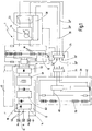
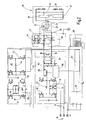
- FIG. 1 in the form of a block diagram and in Fig. 2
- Charging system 1 shown in more detail is designed in the manner of a charging station or charging station for charging vehicle batteries 26 in electric vehicles 28.
- the charging system 1 comprises a mains charging stage 12, which in the exemplary embodiment shown is connected on the input side to a single-phase AC network 10 with a phase or outer conductor Ph, a neutral conductor N and a protective conductor PN.
- the mains charging stage 12 includes an AC / DC converter 14, to whose output a Pufferakkumulator 16 is connected.
- the AC / DC converter 14 has a diode bridge 15 with a power factor correction filter 60, also referred to as a PFC module.
- the power factor correction filter 60 ensures that the diode bridge 15, which is the output side connected to the Pufferakkumulator 16, no excessive peak voltages outputs. The temporal voltage curve is therefore not triangular at the output of the diode bridge, but sinusoidal.
- the power factor correction filter comprises a DC / DC converter 61 for increasing the voltage with a high-frequency diode bridge 62 whose output frequency is a multiple of the mains frequency and whose output voltage is matched to the voltage requirements of the buffer accumulator 16. The latter is effected by the output capacitor 63.
- the Pufferakkumulator 16 has a plurality of individual cells 18, which are connected in series and possibly also in parallel.
- the buffer accumulator 16 is connected on the input side to a battery management system (BMS) 20 for controlling the charging process and for adjusting the state of charge of the accumulator cells 18.
- BMS battery management system
- the battery management system 20 ensures that each individual cell 18 is monitored during the charging and discharging process, so that it can also come locally to no overcharging, which could lead to an inadmissible increase in temperature.
- the charging system further comprises a fast charging stage 22, which is connected on the input side to the Pufferakkumulator 16 and the output side has a charging port 24, which is temporarily connected to the vehicle battery 28 of an electric vehicle 28 for charging purposes.
- the charging connection 24 contains a plug connection with two charging contacts 30 ', 30 "for the current-carrying cables 32', 32" and with two data contacts 34 ', 34 ".
- the data contacts 34', 34" form an interface in a bus system , For example, a CAN bus 35, via which a data exchange between a vehicle-mounted control device 36 and a microprocessor-based control device 38 in the fast charging stage 22 takes place.
- the vehicle-side control device 36 is equipped with a voltage divider 40 for measuring the battery voltage and a shunt 42 for measuring the charging current.
- the analog current and voltage-dependent signals detected by the control device 36 in this way are transmitted in digitized form via the data contacts 34 ', 34 "transmitted to the control device 38 of the rapid charging stage 22 for evaluation and for controlling a arranged in the fast charging stage DC / DC inverter 44.
- a wireless connection via an induction path is conceivable instead of the galvanic connection via the charging contacts 30 ', 30 "in a conductive charging system, but also wireless data transmission instead of the galvanic connection via the data contacts 34', 34" an inductive or capacitive coupling path, a radio link, an infrared link or a Bluetooth route possible.
- the buffer accumulator 16 ensures that very high currents can be withdrawn from the charging system 1 for charging the vehicle accumulator 26 via the fast charging stage 22.
- the charging of the Pufferakkumulators 16 from the AC mains 10 requires no fast charge.
- the charging can instead be uniformly at moderate currents on the order of 16 to 32 amps from the AC network 10, without causing an overload.
- a special feature of the invention is that on the output side of the Pufferakkumulator 16 also a recovery stage 46 is connected, which has a microprocessor-based switching unit 48 and via a DC / AC inverter 50 at a feed point 52 can be connected to the AC mains 10.
- the regenerative stage 46 has a DC / DC converter 72 connected to the buffer accumulator 16, a high-frequency transformer 74 connected thereto, and a diode bridge 76 connected thereto and carrying out the DC / AC conversion.
- the diode bridge can be charged via a filter capacitor 79 connected to a transistor bridge 78 to the amplitude voltage at the instantaneous mains frequency of the AC network 10.
- the charging capacity of the buffer accumulator 16 is dimensioned so that it meets the charging requirements of the arriving motor vehicles.
- the latter means that a relatively large amount of electrical energy is always stored in the buffer accumulator 16 of the charging stations, which can be fed back briefly in the event of the occurrence of a peak load in the AC network 10. Since there is direct access to the buffer accumulator 16 via the charging system 1, a very fast switching operation is possible. Thus, the waiting time can be bridged until the connection of other peak load power plants without an inadmissible load reduction in the AC network 10.
- the charging system also comprises a central controller 54 which has a frequency comparator 58 which is acted upon on the input side by the mains frequency and has an output side via a respective switching unit 56, 48 with the mains charging stage 12 and the regenerative stage 46.
- About the frequency comparator 58 is controlled in accordance with a deviation of the mains frequency of a predetermined frequency threshold via the respective switching unit, either the mains charging or the recovery stage.
- the grid frequency is 50 Hz. If the AC grid is overloaded, the grid frequency decreases.
- the feedback stage 46 is switched through via the frequency comparator 58 and the switching unit 48 and the mains charging stage 12 is switched off via the switching unit 56 when the grid frequency falls below a predetermined frequency threshold, for example 48.5 Hz.
- a predetermined frequency threshold for example 48.5 Hz.
- the central controller 54 also has an operator station 80 for data input and output or for an Internet remote control 82.
- the invention relates to a charging system for electric vehicles.
- the charging system comprises an input side via a connection point to an AC mains 10 connectable, an AC / DC converter having power charging stage 12, a control device 38 for monitoring a charging process and at least one output side charging port 24, which latter is temporarily connectable to aggyakkumulator 26.
- a special feature of the invention consists in that a buffer accumulator 16 having a significantly higher charging capacity than the vehicle accumulator 26 is connected to the mains charging stage 12.
- the controller 38 and a DC / DC converter 44 comprehensive, on the output side via the charging port 24 temporarily connectable to a vehicle battery 26 fast charging stage 22 is connected.
- the buffer accumulator 16 on the output side via a switching unit 48 and a DC / AC inverter 50 having feedback stage 46 at a feed point 52 to the AC network 10 aufschaltbar.
Landscapes
- Engineering & Computer Science (AREA)
- Power Engineering (AREA)
- Transportation (AREA)
- Mechanical Engineering (AREA)
- Charge And Discharge Circuits For Batteries Or The Like (AREA)
- Electric Propulsion And Braking For Vehicles (AREA)
- Secondary Cells (AREA)
Priority Applications (1)
| Application Number | Priority Date | Filing Date | Title |
|---|---|---|---|
| PL10778955T PL2496436T3 (pl) | 2009-11-05 | 2010-11-03 | System ładowania pojazdów elektrycznych |
Applications Claiming Priority (2)
| Application Number | Priority Date | Filing Date | Title |
|---|---|---|---|
| DE102009046422A DE102009046422A1 (de) | 2009-11-05 | 2009-11-05 | Ladesystem für Elektrofahrzeuge |
| PCT/EP2010/066706 WO2011054849A2 (de) | 2009-11-05 | 2010-11-03 | Ladesystem für elektrofahrzeuge |
Publications (2)
| Publication Number | Publication Date |
|---|---|
| EP2496436A2 EP2496436A2 (de) | 2012-09-12 |
| EP2496436B1 true EP2496436B1 (de) | 2018-04-18 |
Family
ID=43852693
Family Applications (1)
| Application Number | Title | Priority Date | Filing Date |
|---|---|---|---|
| EP10778955.4A Active EP2496436B1 (de) | 2009-11-05 | 2010-11-03 | Ladesystem für elektrofahrzeuge |
Country Status (9)
| Country | Link |
|---|---|
| US (1) | US20120280655A1 (pl) |
| EP (1) | EP2496436B1 (pl) |
| CN (1) | CN102712262B (pl) |
| DE (1) | DE102009046422A1 (pl) |
| DK (1) | DK2496436T3 (pl) |
| ES (1) | ES2676169T3 (pl) |
| PL (1) | PL2496436T3 (pl) |
| TR (1) | TR201809350T4 (pl) |
| WO (1) | WO2011054849A2 (pl) |
Cited By (1)
| Publication number | Priority date | Publication date | Assignee | Title |
|---|---|---|---|---|
| EP4034419B1 (en) * | 2019-09-26 | 2024-09-11 | Autostore Technology AS | System and method for power management |
Families Citing this family (42)
| Publication number | Priority date | Publication date | Assignee | Title |
|---|---|---|---|---|
| US8841881B2 (en) | 2010-06-02 | 2014-09-23 | Bryan Marc Failing | Energy transfer with vehicles |
| DE102010042328A1 (de) * | 2010-10-12 | 2012-04-12 | Robert Bosch Gmbh | Verfahren zum Überwachen des Ladebetriebs eines Energiespeichers in einem Fahrzeug und Ladesystem zum Laden eines Energiespeichers in einem Fahrzeug |
| CN102541010A (zh) * | 2012-01-06 | 2012-07-04 | 中国电力科学研究院 | 一种电动汽车监控系统及其控制方法 |
| WO2013104408A1 (de) * | 2012-01-09 | 2013-07-18 | Siemens Aktiengesellschaft | Ladeeinrichtung |
| EP2647522B1 (de) * | 2012-04-03 | 2020-01-22 | Enrichment Technology Company Ltd. | Stromtankstelle mit Schnellladestationen |
| KR101409152B1 (ko) * | 2012-07-18 | 2014-06-17 | 엘에스산전 주식회사 | 충전 장치 및 이의 동작 방법 |
| DE102012014940A1 (de) | 2012-07-27 | 2014-01-30 | Volkswagen Aktiengesellschaft | Vorrichtung zum Laden eines Akkumulators |
| DE102012221133A1 (de) * | 2012-11-20 | 2014-05-22 | Robert Bosch Gmbh | Vorrichtung zum Testen und Warten einer Hochvoltbatterie und Verwendungen dieser Vorrichtung |
| DE102013200949A1 (de) * | 2013-01-22 | 2014-07-24 | Siemens Aktiengesellschaft | Ladeeinrichtung zum Laden einer Anzahl N von Elektrofahrzeugen und Ladestation |
| WO2014160488A1 (en) * | 2013-03-13 | 2014-10-02 | Ideal Power, Inc. | Methods, systems, and devices for improved electric vehicle charging |
| CN104238605B (zh) * | 2013-06-20 | 2016-08-24 | 纽福克斯光电科技(上海)有限公司 | 一种电瓶状态显示控制系统及控制方法 |
| CN103294045B (zh) * | 2013-07-02 | 2015-08-26 | 上海中科深江电动车辆有限公司 | 基于蓝牙技术的电动车辆充电管理系统及方法 |
| US9893557B2 (en) | 2013-07-12 | 2018-02-13 | Schneider Electric USA, Inc. | Method and device for foreign object detection in induction electric charger |
| GB2520318B (en) * | 2013-11-18 | 2015-11-11 | Tana Leonardus Wondergem | Automatic Supply Devices |
| WO2015075212A1 (de) * | 2013-11-22 | 2015-05-28 | Hochschule Für Angewandte Wissenschaften Deggendorf | Ladestation für elektrofahrzeuge |
| EP2875986A1 (de) * | 2013-11-22 | 2015-05-27 | Hochschule für angewandte Wissenschaften Deggendorf | Ladestation für Elektrofahrzeuge mit integrierter Regelungseinrichtung zur Regulierung der abgegebenen Ladeleistung mehrerer Ladepunkte |
| EP2875985A1 (de) * | 2013-11-22 | 2015-05-27 | Hochschule für angewandte Wissenschaften Deggendorf | Ladestation für Elektrofahrzeuge mit integriertem Energiespeicher |
| DE102014219504B4 (de) | 2014-09-26 | 2022-12-08 | Vitesco Technologies GmbH | Drahtloses Batterieladesystem mit Notabschaltung für eine Fahrbatterie eines Elektrofahrzeugs |
| CN105576731A (zh) * | 2014-10-17 | 2016-05-11 | 天宝电子(惠州)有限公司 | 一种车载充电与逆变双向变流电源系统 |
| US9829599B2 (en) | 2015-03-23 | 2017-11-28 | Schneider Electric USA, Inc. | Sensor and method for foreign object detection in induction electric charger |
| US10112495B2 (en) * | 2015-07-27 | 2018-10-30 | Ford Global Technologies, Llc | Vehicle wireless charging system including an inverter to control a voltage input to a vehicle power converter |
| DE102015112752A1 (de) * | 2015-08-04 | 2017-02-09 | Wobben Properties Gmbh | Elektrofahrzeug-Ladestation und Verfahren zum Steuern einer Elektrofahrzeug-Ladestation |
| DE102016103011A1 (de) | 2016-02-22 | 2017-08-24 | Dr. Ing. H.C. F. Porsche Aktiengesellschaft | Verfahren und Vorrichtung zum Betrieb von Ladestationen |
| CN108001247A (zh) * | 2016-11-01 | 2018-05-08 | 华盛新能源科技(深圳)有限公司 | 一种恒功率带电网检测调节设备及方法 |
| DE102017207102A1 (de) * | 2017-03-13 | 2018-09-13 | Bayerische Motoren Werke Aktiengesellschaft | Stationärspeicher zum Zwischenspeichern von elektrischer Energie in einem elektrischen Versorgungsnetz sowie Betriebsverfahren und Nachrüstmodul für den Stationärspeicher |
| DE102017108579A1 (de) | 2017-04-21 | 2018-10-25 | Wobben Properties Gmbh | Verfahren zum Betreiben einer Ladestation |
| DE102017208392B4 (de) | 2017-05-18 | 2022-02-24 | Audi Ag | Verfahren zum Betreiben einer Ladevorrichtung für ein Kraftfahrzeug während eines Ladevorgangs sowie Ladevorrichtung und Kraftfahrzeug |
| DE102017008343B4 (de) | 2017-09-05 | 2022-07-14 | Patrick Kempka | System zum induktiven Laden eines elektrischen Fahrzeugs |
| DE102017123348A1 (de) * | 2017-10-09 | 2019-04-11 | Dr. Ing. H.C. F. Porsche Aktiengesellschaft | Wechselrichter für ein Elektroauto |
| EP3682527A4 (en) | 2017-10-13 | 2021-11-10 | The Governing Council of the University of Toronto | ON-BOARD BIDIRECTIONAL AC QUICK CHARGER FOR ELECTRIC VEHICLES |
| DE102017131109A1 (de) * | 2017-12-22 | 2019-06-27 | Innogy Se | Ladestation für Elektrofahrzeuge sowie Verfahren zum Betreiben einer Ladestation |
| US10351004B1 (en) * | 2018-01-03 | 2019-07-16 | Lear Corporation | Pre-charging DC link capacitor of on-board charger (OBC) using traction battery |
| DE102018102566A1 (de) * | 2018-02-06 | 2019-08-08 | Dr. Ing. H.C. F. Porsche Aktiengesellschaft | Ladesystem mit mindestens einer Ladesäule für Elektrofahrzeuge und Verfahren zum Laden eines oder mehrerer Elektrofahrzeuge |
| GB2572758A (en) * | 2018-04-05 | 2019-10-16 | Moog Unna Gmbh | Charging station for electric vehicles |
| CN108599328A (zh) * | 2018-06-15 | 2018-09-28 | 深圳壹智云科技有限公司 | 一种基于超级电容的慢充快放的储能充放电装置 |
| WO2021051086A1 (en) * | 2019-09-13 | 2021-03-18 | Enel X North America, Inc. | High power bidirectional grid connected charger with split battery architecture |
| FR3102019B1 (fr) * | 2019-10-11 | 2021-10-22 | Nw Joules | Dispositif de recharge rapide d’un vehicule automobile |
| DE102019217784A1 (de) * | 2019-11-19 | 2021-05-20 | Volkswagen Aktiengesellschaft | Ladeinfrastruktur zur Ladung eines Kraftfahrzeugs |
| DE102020113235A1 (de) * | 2020-05-15 | 2021-11-18 | Juice Technology AG | Ladestation für Elektrofahrzeuge |
| US11349386B2 (en) * | 2020-06-17 | 2022-05-31 | Hyundai Motor Company | Apparatus and method for charging battery of vehicle |
| DE102020125849A1 (de) * | 2020-10-02 | 2022-04-07 | Zf Cv Systems Global Gmbh | Verfahren zum Austauschen von Energie, Verarbeitungseinheit und Fahrzeug |
| CN113659687A (zh) * | 2021-07-02 | 2021-11-16 | 北京新能源汽车股份有限公司 | 充电桩电路和充电桩 |
Citations (1)
| Publication number | Priority date | Publication date | Assignee | Title |
|---|---|---|---|---|
| US20040130292A1 (en) * | 2000-06-14 | 2004-07-08 | Buchanan William D. | Battery charging system and method |
Family Cites Families (25)
| Publication number | Priority date | Publication date | Assignee | Title |
|---|---|---|---|---|
| JP2783555B2 (ja) * | 1988-09-26 | 1998-08-06 | 株式会社東芝 | 電力変換装置 |
| US5202617A (en) * | 1991-10-15 | 1993-04-13 | Norvik Technologies Inc. | Charging station for electric vehicles |
| JP3178146B2 (ja) * | 1992-12-25 | 2001-06-18 | 富士電機株式会社 | 電気自動車の電気システム |
| DE4442825A1 (de) * | 1993-12-01 | 1995-06-08 | Aabh Patent Holdings | System zum Speichern elektrischer Energie |
| US5926004A (en) * | 1997-10-10 | 1999-07-20 | Schott Power Systems Incorporated | Method and apparatus for charging one or more electric vehicles |
| US6088250A (en) * | 1998-05-29 | 2000-07-11 | The Aerospace Corporation | Power converters for multiple input power supplies |
| US6981895B2 (en) * | 1999-08-23 | 2006-01-03 | Patrick Potega | Interface apparatus for selectively connecting electrical devices |
| US6664762B2 (en) * | 2001-08-21 | 2003-12-16 | Power Designers, Llc | High voltage battery charger |
| US6784624B2 (en) * | 2001-12-19 | 2004-08-31 | Nicholas Buonocunto | Electronic ballast system having emergency lighting provisions |
| US6791295B1 (en) * | 2003-02-20 | 2004-09-14 | Ford Global Technologies, Llc | Method and apparatus for charging a high voltage battery of an automotive vehicle having a high voltage battery and a low voltage battery |
| DE10331084A1 (de) * | 2003-07-09 | 2005-03-24 | Aloys Wobben | Kraftfahrzeug |
| US7057376B2 (en) * | 2004-01-14 | 2006-06-06 | Vanner, Inc. | Power management system for vehicles |
| JP4182957B2 (ja) * | 2004-07-06 | 2008-11-19 | 株式会社デンソー | 発電制御装置 |
| JP4645808B2 (ja) * | 2004-12-17 | 2011-03-09 | サンケン電気株式会社 | 3相電力変換装置 |
| CA2523240C (en) * | 2005-10-11 | 2009-12-08 | Delaware Systems Inc. | Universal battery module and controller therefor |
| JP4615439B2 (ja) * | 2005-12-28 | 2011-01-19 | 株式会社Nttファシリティーズ | 二次電池管理装置、二次電池管理方法及びプログラム |
| CN101150259B (zh) * | 2006-09-18 | 2010-05-12 | 比亚迪股份有限公司 | 电动车充电系统 |
| JP5011940B2 (ja) * | 2006-10-16 | 2012-08-29 | トヨタ自動車株式会社 | 電源装置、および車両 |
| JP4320336B2 (ja) * | 2006-10-24 | 2009-08-26 | Tdk株式会社 | スイッチング電源装置 |
| JP4400632B2 (ja) * | 2007-02-20 | 2010-01-20 | Tdk株式会社 | スイッチング電源装置 |
| KR100908716B1 (ko) * | 2007-03-02 | 2009-07-22 | 삼성에스디아이 주식회사 | 배터리 관리 시스템 및 그의 구동 방법 |
| WO2009042214A1 (en) * | 2007-09-26 | 2009-04-02 | Governing Dynamics, Llc | Self-charging electric vehicles and aircraft, and wireless energy distribution system |
| JP5134904B2 (ja) * | 2007-10-10 | 2013-01-30 | 富士重工業株式会社 | 電気自動車の充電装置 |
| US7889524B2 (en) * | 2007-10-19 | 2011-02-15 | Illinois Institute Of Technology | Integrated bi-directional converter for plug-in hybrid electric vehicles |
| CN101946351B (zh) * | 2008-02-19 | 2014-04-02 | 博隆能源股份有限公司 | 用于给电动交通工具充电的燃料电池系统 |
-
2009
- 2009-11-05 DE DE102009046422A patent/DE102009046422A1/de not_active Withdrawn
-
2010
- 2010-11-03 US US13/508,099 patent/US20120280655A1/en not_active Abandoned
- 2010-11-03 CN CN201080050222.4A patent/CN102712262B/zh not_active Expired - Fee Related
- 2010-11-03 TR TR2018/09350T patent/TR201809350T4/tr unknown
- 2010-11-03 WO PCT/EP2010/066706 patent/WO2011054849A2/de not_active Ceased
- 2010-11-03 DK DK10778955.4T patent/DK2496436T3/en active
- 2010-11-03 PL PL10778955T patent/PL2496436T3/pl unknown
- 2010-11-03 ES ES10778955.4T patent/ES2676169T3/es active Active
- 2010-11-03 EP EP10778955.4A patent/EP2496436B1/de active Active
Patent Citations (1)
| Publication number | Priority date | Publication date | Assignee | Title |
|---|---|---|---|---|
| US20040130292A1 (en) * | 2000-06-14 | 2004-07-08 | Buchanan William D. | Battery charging system and method |
Cited By (1)
| Publication number | Priority date | Publication date | Assignee | Title |
|---|---|---|---|---|
| EP4034419B1 (en) * | 2019-09-26 | 2024-09-11 | Autostore Technology AS | System and method for power management |
Also Published As
| Publication number | Publication date |
|---|---|
| EP2496436A2 (de) | 2012-09-12 |
| DK2496436T3 (en) | 2018-07-16 |
| CN102712262B (zh) | 2015-04-01 |
| WO2011054849A3 (de) | 2012-07-19 |
| DE102009046422A1 (de) | 2011-05-12 |
| PL2496436T3 (pl) | 2018-10-31 |
| ES2676169T3 (es) | 2018-07-17 |
| US20120280655A1 (en) | 2012-11-08 |
| WO2011054849A2 (de) | 2011-05-12 |
| TR201809350T4 (tr) | 2018-07-23 |
| CN102712262A (zh) | 2012-10-03 |
Similar Documents
| Publication | Publication Date | Title |
|---|---|---|
| EP2496436B1 (de) | Ladesystem für elektrofahrzeuge | |
| EP2473370B1 (de) | Starthilfeverfahren und einrichtung für die durchführung des verfahrens | |
| EP3521099B1 (de) | Ladesystem mit mindestens einer ladesäule für elektrofahrzeuge und verfahren zum laden eines oder mehrerer elektrofahrzeuge | |
| DE102012108674B4 (de) | Stromversorgungssystem, Elektrofahrzeug und Ladeadapter | |
| WO2018166815A1 (de) | Stationärspeicher zum zwischenspeichern von elektrischer energie in einem elektrischen versorgungsnetz sowie betriebsverfahren und nachrüstmodul für den stationärspeicher | |
| DE102011007839A1 (de) | Fahrzeugladevorrichtung | |
| WO2014009369A2 (de) | Modularer aufbau von dc-schnellladestationen | |
| WO2014114515A2 (de) | Ladeeinrichtung zum laden einer anzahl n von elektrofahrzeugen und ladestation | |
| EP3708416A1 (de) | Verfahren und ladeeinrichtung zur bestimmung einer maximalen speicherkapazität eines energiespeichers | |
| EP3556594B1 (de) | Verfahren zum betreiben eines fahrzeugs sowie fahrzeug | |
| DE112019005193T5 (de) | Elektrisches speichersystem | |
| WO2009047103A1 (de) | Bordnetz und verfahren zum betreiben eines bordnetzes | |
| EP2875985A1 (de) | Ladestation für Elektrofahrzeuge mit integriertem Energiespeicher | |
| DE102011107269B4 (de) | Verfahren und Vorrichtung zum solargestützten Laden einer Batterie und Ladeeinrichtung | |
| EP2875986A1 (de) | Ladestation für Elektrofahrzeuge mit integrierter Regelungseinrichtung zur Regulierung der abgegebenen Ladeleistung mehrerer Ladepunkte | |
| DE102024109502A1 (de) | Laden von und zu einem kraftfahrzeugbatteriesystem über ein mehrfachanschluss-ladesystem | |
| EP2777129A1 (de) | Ladeeinrichtung | |
| WO2021223968A1 (de) | Elektrisches fahrzeug und verfahren zum betreiben eines elektrischen fahrzeugs | |
| DE102018205040B4 (de) | Ladesystem und Verfahren zum Aufladen eines jeweiligen elektrischen Energiespeichers mehrerer Kraftfahrzeuge sowie stationäre Ladevorrichtung und Kraftfahrzeug | |
| DE102013005104A1 (de) | Vorrichtung und Verfahren zum Auf- und Entladen eines Energiespeichers | |
| DE102014108601A1 (de) | Verfahren zum Anschließen mehrerer Batterieeinheiten an einen zweipoligen Eingang eines bidirektionalen Batteriewandlers sowie bidirektionaler Batteriewandler und Photovoltaikwechselrichter | |
| DE202013012651U1 (de) | Ladestation für Elektrofahrzeuge mit integrierter Regelungseinrichtung zur Regulierung der abgegebenen Ladeleistung mehrerer Ladepunkte | |
| DE102017208363A1 (de) | Verfahren zum Übertragen von elektrischer Leistung und Ladestation | |
| DE102019214258A1 (de) | Energieversorgungsstation und Verfahren zur Energieversorgung für ein Fahrzeug | |
| DE102016220584A1 (de) | Verfahren zum Betrieb eines Stromrichters |
Legal Events
| Date | Code | Title | Description |
|---|---|---|---|
| PUAI | Public reference made under article 153(3) epc to a published international application that has entered the european phase |
Free format text: ORIGINAL CODE: 0009012 |
|
| 17P | Request for examination filed |
Effective date: 20120605 |
|
| AK | Designated contracting states |
Kind code of ref document: A2 Designated state(s): AL AT BE BG CH CY CZ DE DK EE ES FI FR GB GR HR HU IE IS IT LI LT LU LV MC MK MT NL NO PL PT RO RS SE SI SK SM TR |
|
| RIC1 | Information provided on ipc code assigned before grant |
Ipc: H02J 7/34 20060101ALI20130131BHEP Ipc: B60L 11/18 20060101AFI20130131BHEP Ipc: H02J 7/02 20060101ALI20130131BHEP |
|
| RIN1 | Information on inventor provided before grant (corrected) |
Inventor name: SCHNEIDER, DANIEL Inventor name: WICK, THOMAS Inventor name: MARTIN, GILLES |
|
| DAX | Request for extension of the european patent (deleted) | ||
| 17Q | First examination report despatched |
Effective date: 20150730 |
|
| GRAP | Despatch of communication of intention to grant a patent |
Free format text: ORIGINAL CODE: EPIDOSNIGR1 |
|
| INTG | Intention to grant announced |
Effective date: 20171012 |
|
| GRAJ | Information related to disapproval of communication of intention to grant by the applicant or resumption of examination proceedings by the epo deleted |
Free format text: ORIGINAL CODE: EPIDOSDIGR1 |
|
| INTC | Intention to grant announced (deleted) | ||
| GRAS | Grant fee paid |
Free format text: ORIGINAL CODE: EPIDOSNIGR3 |
|
| GRAP | Despatch of communication of intention to grant a patent |
Free format text: ORIGINAL CODE: EPIDOSNIGR1 |
|
| GRAA | (expected) grant |
Free format text: ORIGINAL CODE: 0009210 |
|
| INTG | Intention to grant announced |
Effective date: 20180302 |
|
| RIN1 | Information on inventor provided before grant (corrected) |
Inventor name: WICK, THOMAS Inventor name: MARTIN, GILLES Inventor name: SCHNEIDER, DANIEL |
|
| AK | Designated contracting states |
Kind code of ref document: B1 Designated state(s): AL AT BE BG CH CY CZ DE DK EE ES FI FR GB GR HR HU IE IS IT LI LT LU LV MC MK MT NL NO PL PT RO RS SE SI SK SM TR |
|
| REG | Reference to a national code |
Ref country code: GB Ref legal event code: FG4D Free format text: NOT ENGLISH |
|
| REG | Reference to a national code |
Ref country code: CH Ref legal event code: EP |
|
| REG | Reference to a national code |
Ref country code: AT Ref legal event code: REF Ref document number: 990062 Country of ref document: AT Kind code of ref document: T Effective date: 20180515 |
|
| REG | Reference to a national code |
Ref country code: IE Ref legal event code: FG4D Free format text: LANGUAGE OF EP DOCUMENT: GERMAN |
|
| REG | Reference to a national code |
Ref country code: DE Ref legal event code: R096 Ref document number: 502010014894 Country of ref document: DE |
|
| REG | Reference to a national code |
Ref country code: DK Ref legal event code: T3 Effective date: 20180711 |
|
| REG | Reference to a national code |
Ref country code: ES Ref legal event code: FG2A Ref document number: 2676169 Country of ref document: ES Kind code of ref document: T3 Effective date: 20180717 |
|
| REG | Reference to a national code |
Ref country code: SE Ref legal event code: TRGR |
|
| REG | Reference to a national code |
Ref country code: NL Ref legal event code: FP |
|
| REG | Reference to a national code |
Ref country code: LT Ref legal event code: MG4D Ref country code: NO Ref legal event code: T2 Effective date: 20180418 |
|
| PG25 | Lapsed in a contracting state [announced via postgrant information from national office to epo] |
Ref country code: LT Free format text: LAPSE BECAUSE OF FAILURE TO SUBMIT A TRANSLATION OF THE DESCRIPTION OR TO PAY THE FEE WITHIN THE PRESCRIBED TIME-LIMIT Effective date: 20180418 Ref country code: FI Free format text: LAPSE BECAUSE OF FAILURE TO SUBMIT A TRANSLATION OF THE DESCRIPTION OR TO PAY THE FEE WITHIN THE PRESCRIBED TIME-LIMIT Effective date: 20180418 Ref country code: BG Free format text: LAPSE BECAUSE OF FAILURE TO SUBMIT A TRANSLATION OF THE DESCRIPTION OR TO PAY THE FEE WITHIN THE PRESCRIBED TIME-LIMIT Effective date: 20180718 Ref country code: AL Free format text: LAPSE BECAUSE OF FAILURE TO SUBMIT A TRANSLATION OF THE DESCRIPTION OR TO PAY THE FEE WITHIN THE PRESCRIBED TIME-LIMIT Effective date: 20180418 |
|
| PG25 | Lapsed in a contracting state [announced via postgrant information from national office to epo] |
Ref country code: RS Free format text: LAPSE BECAUSE OF FAILURE TO SUBMIT A TRANSLATION OF THE DESCRIPTION OR TO PAY THE FEE WITHIN THE PRESCRIBED TIME-LIMIT Effective date: 20180418 Ref country code: HR Free format text: LAPSE BECAUSE OF FAILURE TO SUBMIT A TRANSLATION OF THE DESCRIPTION OR TO PAY THE FEE WITHIN THE PRESCRIBED TIME-LIMIT Effective date: 20180418 Ref country code: LV Free format text: LAPSE BECAUSE OF FAILURE TO SUBMIT A TRANSLATION OF THE DESCRIPTION OR TO PAY THE FEE WITHIN THE PRESCRIBED TIME-LIMIT Effective date: 20180418 |
|
| PG25 | Lapsed in a contracting state [announced via postgrant information from national office to epo] |
Ref country code: PT Free format text: LAPSE BECAUSE OF FAILURE TO SUBMIT A TRANSLATION OF THE DESCRIPTION OR TO PAY THE FEE WITHIN THE PRESCRIBED TIME-LIMIT Effective date: 20180820 |
|
| REG | Reference to a national code |
Ref country code: DE Ref legal event code: R079 Ref document number: 502010014894 Country of ref document: DE Free format text: PREVIOUS MAIN CLASS: B60L0011180000 Ipc: B60L0050500000 |
|
| REG | Reference to a national code |
Ref country code: DE Ref legal event code: R097 Ref document number: 502010014894 Country of ref document: DE |
|
| REG | Reference to a national code |
Ref country code: GR Ref legal event code: EP Ref document number: 20180401917 Country of ref document: GR Effective date: 20190109 |
|
| PG25 | Lapsed in a contracting state [announced via postgrant information from national office to epo] |
Ref country code: EE Free format text: LAPSE BECAUSE OF FAILURE TO SUBMIT A TRANSLATION OF THE DESCRIPTION OR TO PAY THE FEE WITHIN THE PRESCRIBED TIME-LIMIT Effective date: 20180418 Ref country code: SK Free format text: LAPSE BECAUSE OF FAILURE TO SUBMIT A TRANSLATION OF THE DESCRIPTION OR TO PAY THE FEE WITHIN THE PRESCRIBED TIME-LIMIT Effective date: 20180418 Ref country code: RO Free format text: LAPSE BECAUSE OF FAILURE TO SUBMIT A TRANSLATION OF THE DESCRIPTION OR TO PAY THE FEE WITHIN THE PRESCRIBED TIME-LIMIT Effective date: 20180418 Ref country code: CZ Free format text: LAPSE BECAUSE OF FAILURE TO SUBMIT A TRANSLATION OF THE DESCRIPTION OR TO PAY THE FEE WITHIN THE PRESCRIBED TIME-LIMIT Effective date: 20180418 |
|
| PLBE | No opposition filed within time limit |
Free format text: ORIGINAL CODE: 0009261 |
|
| STAA | Information on the status of an ep patent application or granted ep patent |
Free format text: STATUS: NO OPPOSITION FILED WITHIN TIME LIMIT |
|
| PG25 | Lapsed in a contracting state [announced via postgrant information from national office to epo] |
Ref country code: SM Free format text: LAPSE BECAUSE OF FAILURE TO SUBMIT A TRANSLATION OF THE DESCRIPTION OR TO PAY THE FEE WITHIN THE PRESCRIBED TIME-LIMIT Effective date: 20180418 |
|
| 26N | No opposition filed |
Effective date: 20190121 |
|
| PG25 | Lapsed in a contracting state [announced via postgrant information from national office to epo] |
Ref country code: SI Free format text: LAPSE BECAUSE OF FAILURE TO SUBMIT A TRANSLATION OF THE DESCRIPTION OR TO PAY THE FEE WITHIN THE PRESCRIBED TIME-LIMIT Effective date: 20180418 |
|
| REG | Reference to a national code |
Ref country code: DK Ref legal event code: EBP Effective date: 20181130 |
|
| REG | Reference to a national code |
Ref country code: NL Ref legal event code: MM Effective date: 20181201 |
|
| PG25 | Lapsed in a contracting state [announced via postgrant information from national office to epo] |
Ref country code: MC Free format text: LAPSE BECAUSE OF FAILURE TO SUBMIT A TRANSLATION OF THE DESCRIPTION OR TO PAY THE FEE WITHIN THE PRESCRIBED TIME-LIMIT Effective date: 20180418 Ref country code: LU Free format text: LAPSE BECAUSE OF NON-PAYMENT OF DUE FEES Effective date: 20181103 |
|
| REG | Reference to a national code |
Ref country code: IE Ref legal event code: MM4A |
|
| PG25 | Lapsed in a contracting state [announced via postgrant information from national office to epo] |
Ref country code: GR Free format text: LAPSE BECAUSE OF NON-PAYMENT OF DUE FEES Effective date: 20190605 Ref country code: NL Free format text: LAPSE BECAUSE OF NON-PAYMENT OF DUE FEES Effective date: 20181201 |
|
| PG25 | Lapsed in a contracting state [announced via postgrant information from national office to epo] |
Ref country code: DK Free format text: LAPSE BECAUSE OF NON-PAYMENT OF DUE FEES Effective date: 20181130 Ref country code: IE Free format text: LAPSE BECAUSE OF NON-PAYMENT OF DUE FEES Effective date: 20181103 |
|
| REG | Reference to a national code |
Ref country code: AT Ref legal event code: MM01 Ref document number: 990062 Country of ref document: AT Kind code of ref document: T Effective date: 20181103 |
|
| PG25 | Lapsed in a contracting state [announced via postgrant information from national office to epo] |
Ref country code: MT Free format text: LAPSE BECAUSE OF FAILURE TO SUBMIT A TRANSLATION OF THE DESCRIPTION OR TO PAY THE FEE WITHIN THE PRESCRIBED TIME-LIMIT Effective date: 20180418 Ref country code: AT Free format text: LAPSE BECAUSE OF NON-PAYMENT OF DUE FEES Effective date: 20181103 |
|
| PG25 | Lapsed in a contracting state [announced via postgrant information from national office to epo] |
Ref country code: CY Free format text: LAPSE BECAUSE OF FAILURE TO SUBMIT A TRANSLATION OF THE DESCRIPTION OR TO PAY THE FEE WITHIN THE PRESCRIBED TIME-LIMIT Effective date: 20180418 Ref country code: MK Free format text: LAPSE BECAUSE OF NON-PAYMENT OF DUE FEES Effective date: 20180418 Ref country code: HU Free format text: LAPSE BECAUSE OF FAILURE TO SUBMIT A TRANSLATION OF THE DESCRIPTION OR TO PAY THE FEE WITHIN THE PRESCRIBED TIME-LIMIT; INVALID AB INITIO Effective date: 20101103 |
|
| PG25 | Lapsed in a contracting state [announced via postgrant information from national office to epo] |
Ref country code: IS Free format text: LAPSE BECAUSE OF FAILURE TO SUBMIT A TRANSLATION OF THE DESCRIPTION OR TO PAY THE FEE WITHIN THE PRESCRIBED TIME-LIMIT Effective date: 20180818 |
|
| PGFP | Annual fee paid to national office [announced via postgrant information from national office to epo] |
Ref country code: DE Payment date: 20211122 Year of fee payment: 12 Ref country code: TR Payment date: 20211101 Year of fee payment: 12 Ref country code: SE Payment date: 20211118 Year of fee payment: 12 Ref country code: FR Payment date: 20211122 Year of fee payment: 12 Ref country code: NO Payment date: 20211123 Year of fee payment: 12 Ref country code: GB Payment date: 20211118 Year of fee payment: 12 |
|
| PGFP | Annual fee paid to national office [announced via postgrant information from national office to epo] |
Ref country code: IT Payment date: 20211123 Year of fee payment: 12 Ref country code: BE Payment date: 20211118 Year of fee payment: 12 |
|
| PGFP | Annual fee paid to national office [announced via postgrant information from national office to epo] |
Ref country code: PL Payment date: 20211102 Year of fee payment: 12 |
|
| PGFP | Annual fee paid to national office [announced via postgrant information from national office to epo] |
Ref country code: ES Payment date: 20220121 Year of fee payment: 12 |
|
| PGFP | Annual fee paid to national office [announced via postgrant information from national office to epo] |
Ref country code: CH Payment date: 20221201 Year of fee payment: 13 |
|
| REG | Reference to a national code |
Ref country code: DE Ref legal event code: R119 Ref document number: 502010014894 Country of ref document: DE |
|
| REG | Reference to a national code |
Ref country code: NO Ref legal event code: MMEP |
|
| REG | Reference to a national code |
Ref country code: SE Ref legal event code: EUG |
|
| GBPC | Gb: european patent ceased through non-payment of renewal fee |
Effective date: 20221103 |
|
| REG | Reference to a national code |
Ref country code: BE Ref legal event code: MM Effective date: 20221130 |
|
| PG25 | Lapsed in a contracting state [announced via postgrant information from national office to epo] |
Ref country code: NO Free format text: LAPSE BECAUSE OF NON-PAYMENT OF DUE FEES Effective date: 20221130 |
|
| PG25 | Lapsed in a contracting state [announced via postgrant information from national office to epo] |
Ref country code: SE Free format text: LAPSE BECAUSE OF NON-PAYMENT OF DUE FEES Effective date: 20221104 |
|
| PG25 | Lapsed in a contracting state [announced via postgrant information from national office to epo] |
Ref country code: IT Free format text: LAPSE BECAUSE OF NON-PAYMENT OF DUE FEES Effective date: 20221103 Ref country code: GB Free format text: LAPSE BECAUSE OF NON-PAYMENT OF DUE FEES Effective date: 20221103 Ref country code: DE Free format text: LAPSE BECAUSE OF NON-PAYMENT OF DUE FEES Effective date: 20230601 |
|
| PG25 | Lapsed in a contracting state [announced via postgrant information from national office to epo] |
Ref country code: FR Free format text: LAPSE BECAUSE OF NON-PAYMENT OF DUE FEES Effective date: 20221130 Ref country code: BE Free format text: LAPSE BECAUSE OF NON-PAYMENT OF DUE FEES Effective date: 20221130 |
|
| REG | Reference to a national code |
Ref country code: ES Ref legal event code: FD2A Effective date: 20231228 |
|
| PG25 | Lapsed in a contracting state [announced via postgrant information from national office to epo] |
Ref country code: ES Free format text: LAPSE BECAUSE OF NON-PAYMENT OF DUE FEES Effective date: 20221104 |
|
| PG25 | Lapsed in a contracting state [announced via postgrant information from national office to epo] |
Ref country code: ES Free format text: LAPSE BECAUSE OF NON-PAYMENT OF DUE FEES Effective date: 20221104 |
|
| PG25 | Lapsed in a contracting state [announced via postgrant information from national office to epo] |
Ref country code: PL Free format text: LAPSE BECAUSE OF NON-PAYMENT OF DUE FEES Effective date: 20221103 |
|
| REG | Reference to a national code |
Ref country code: CH Ref legal event code: PL |
|
| PG25 | Lapsed in a contracting state [announced via postgrant information from national office to epo] |
Ref country code: CH Free format text: LAPSE BECAUSE OF NON-PAYMENT OF DUE FEES Effective date: 20231130 |
|
| PG25 | Lapsed in a contracting state [announced via postgrant information from national office to epo] |
Ref country code: CH Free format text: LAPSE BECAUSE OF NON-PAYMENT OF DUE FEES Effective date: 20231130 |
|
| PG25 | Lapsed in a contracting state [announced via postgrant information from national office to epo] |
Ref country code: TR Free format text: LAPSE BECAUSE OF NON-PAYMENT OF DUE FEES Effective date: 20221103 |