EP2493734B1 - Ventileinsatz für eine ventilpatrone, korrespondierende ventilpatrone für ein magnetventil, magnetventil mit einer derartigen ventilpatrone und verfahren zur herstellung eines ventileinsatzes - Google Patents
Ventileinsatz für eine ventilpatrone, korrespondierende ventilpatrone für ein magnetventil, magnetventil mit einer derartigen ventilpatrone und verfahren zur herstellung eines ventileinsatzes Download PDFInfo
- Publication number
- EP2493734B1 EP2493734B1 EP10752789.7A EP10752789A EP2493734B1 EP 2493734 B1 EP2493734 B1 EP 2493734B1 EP 10752789 A EP10752789 A EP 10752789A EP 2493734 B1 EP2493734 B1 EP 2493734B1
- Authority
- EP
- European Patent Office
- Prior art keywords
- valve
- bore
- insert
- constriction
- trumpet
- Prior art date
- Legal status (The legal status is an assumption and is not a legal conclusion. Google has not performed a legal analysis and makes no representation as to the accuracy of the status listed.)
- Active
Links
Images


Classifications
-
- B—PERFORMING OPERATIONS; TRANSPORTING
- B60—VEHICLES IN GENERAL
- B60T—VEHICLE BRAKE CONTROL SYSTEMS OR PARTS THEREOF; BRAKE CONTROL SYSTEMS OR PARTS THEREOF, IN GENERAL; ARRANGEMENT OF BRAKING ELEMENTS ON VEHICLES IN GENERAL; PORTABLE DEVICES FOR PREVENTING UNWANTED MOVEMENT OF VEHICLES; VEHICLE MODIFICATIONS TO FACILITATE COOLING OF BRAKES
- B60T8/00—Arrangements for adjusting wheel-braking force to meet varying vehicular or ground-surface conditions, e.g. limiting or varying distribution of braking force
- B60T8/32—Arrangements for adjusting wheel-braking force to meet varying vehicular or ground-surface conditions, e.g. limiting or varying distribution of braking force responsive to a speed condition, e.g. acceleration or deceleration
- B60T8/34—Arrangements for adjusting wheel-braking force to meet varying vehicular or ground-surface conditions, e.g. limiting or varying distribution of braking force responsive to a speed condition, e.g. acceleration or deceleration having a fluid pressure regulator responsive to a speed condition
- B60T8/36—Arrangements for adjusting wheel-braking force to meet varying vehicular or ground-surface conditions, e.g. limiting or varying distribution of braking force responsive to a speed condition, e.g. acceleration or deceleration having a fluid pressure regulator responsive to a speed condition including a pilot valve responding to an electromagnetic force
- B60T8/3615—Electromagnetic valves specially adapted for anti-lock brake and traction control systems
-
- B—PERFORMING OPERATIONS; TRANSPORTING
- B60—VEHICLES IN GENERAL
- B60T—VEHICLE BRAKE CONTROL SYSTEMS OR PARTS THEREOF; BRAKE CONTROL SYSTEMS OR PARTS THEREOF, IN GENERAL; ARRANGEMENT OF BRAKING ELEMENTS ON VEHICLES IN GENERAL; PORTABLE DEVICES FOR PREVENTING UNWANTED MOVEMENT OF VEHICLES; VEHICLE MODIFICATIONS TO FACILITATE COOLING OF BRAKES
- B60T8/00—Arrangements for adjusting wheel-braking force to meet varying vehicular or ground-surface conditions, e.g. limiting or varying distribution of braking force
- B60T8/32—Arrangements for adjusting wheel-braking force to meet varying vehicular or ground-surface conditions, e.g. limiting or varying distribution of braking force responsive to a speed condition, e.g. acceleration or deceleration
- B60T8/34—Arrangements for adjusting wheel-braking force to meet varying vehicular or ground-surface conditions, e.g. limiting or varying distribution of braking force responsive to a speed condition, e.g. acceleration or deceleration having a fluid pressure regulator responsive to a speed condition
- B60T8/36—Arrangements for adjusting wheel-braking force to meet varying vehicular or ground-surface conditions, e.g. limiting or varying distribution of braking force responsive to a speed condition, e.g. acceleration or deceleration having a fluid pressure regulator responsive to a speed condition including a pilot valve responding to an electromagnetic force
- B60T8/3615—Electromagnetic valves specially adapted for anti-lock brake and traction control systems
- B60T8/363—Electromagnetic valves specially adapted for anti-lock brake and traction control systems in hydraulic systems
-
- F—MECHANICAL ENGINEERING; LIGHTING; HEATING; WEAPONS; BLASTING
- F16—ENGINEERING ELEMENTS AND UNITS; GENERAL MEASURES FOR PRODUCING AND MAINTAINING EFFECTIVE FUNCTIONING OF MACHINES OR INSTALLATIONS; THERMAL INSULATION IN GENERAL
- F16K—VALVES; TAPS; COCKS; ACTUATING-FLOATS; DEVICES FOR VENTING OR AERATING
- F16K31/00—Actuating devices; Operating means; Releasing devices
- F16K31/02—Actuating devices; Operating means; Releasing devices electric; magnetic
- F16K31/06—Actuating devices; Operating means; Releasing devices electric; magnetic using a magnet, e.g. diaphragm valves, cutting off by means of a liquid
- F16K31/0644—One-way valve
- F16K31/0655—Lift valves
-
- F—MECHANICAL ENGINEERING; LIGHTING; HEATING; WEAPONS; BLASTING
- F16—ENGINEERING ELEMENTS AND UNITS; GENERAL MEASURES FOR PRODUCING AND MAINTAINING EFFECTIVE FUNCTIONING OF MACHINES OR INSTALLATIONS; THERMAL INSULATION IN GENERAL
- F16K—VALVES; TAPS; COCKS; ACTUATING-FLOATS; DEVICES FOR VENTING OR AERATING
- F16K47/00—Means in valves for absorbing fluid energy
- F16K47/08—Means in valves for absorbing fluid energy for decreasing pressure or noise level and having a throttling member separate from the closure member, e.g. screens, slots, labyrinths
-
- Y—GENERAL TAGGING OF NEW TECHNOLOGICAL DEVELOPMENTS; GENERAL TAGGING OF CROSS-SECTIONAL TECHNOLOGIES SPANNING OVER SEVERAL SECTIONS OF THE IPC; TECHNICAL SUBJECTS COVERED BY FORMER USPC CROSS-REFERENCE ART COLLECTIONS [XRACs] AND DIGESTS
- Y10—TECHNICAL SUBJECTS COVERED BY FORMER USPC
- Y10T—TECHNICAL SUBJECTS COVERED BY FORMER US CLASSIFICATION
- Y10T29/00—Metal working
- Y10T29/49—Method of mechanical manufacture
- Y10T29/49405—Valve or choke making
- Y10T29/49412—Valve or choke making with assembly, disassembly or composite article making
- Y10T29/49416—Valve or choke making with assembly, disassembly or composite article making with material shaping or cutting
-
- Y—GENERAL TAGGING OF NEW TECHNOLOGICAL DEVELOPMENTS; GENERAL TAGGING OF CROSS-SECTIONAL TECHNOLOGIES SPANNING OVER SEVERAL SECTIONS OF THE IPC; TECHNICAL SUBJECTS COVERED BY FORMER USPC CROSS-REFERENCE ART COLLECTIONS [XRACs] AND DIGESTS
- Y10—TECHNICAL SUBJECTS COVERED BY FORMER USPC
- Y10T—TECHNICAL SUBJECTS COVERED BY FORMER US CLASSIFICATION
- Y10T29/00—Metal working
- Y10T29/49—Method of mechanical manufacture
- Y10T29/49405—Valve or choke making
- Y10T29/49426—Valve or choke making including metal shaping and diverse operation
Definitions
- the invention relates to a valve core for a valve cartridge according to the preamble of independent claim 1, and an associated valve cartridge for a solenoid valve, an associated solenoid valve and a method for producing a valve core according to the preamble of independent claim 6.
- Solenoid valves in particular for hydraulic power units, which can be used, for example, in an anti-lock braking system (ABS) or a traction control system (ASR system) or an electronic stability program system (ESP system), are known from the prior art.
- a solenoid valve as a technical component is used to control the inlet or outlet of gases or liquids or to control the flow direction or regulate.
- valve cartridge for a solenoid valve and an associated solenoid valve are described with such a valve cartridge.
- the described valve cartridge comprises a capsule, a magnet armature movably guided inside the capsule, a valve insert which is inserted with a first end into the capsule and a valve body which is pressed into a second end of the valve insert and has a main valve seat.
- the magnet armature which is moved by a generated magnetic force, moves a tappet guided inside the valve insert, which has a closing element with a sealing element, wherein the sealing element dips sealingly into the main valve seat of the valve body for carrying out a sealing function.
- valve core is designed as a one-piece slotted sleeve
- valve body is designed as a hood-shaped sleeve.
- the valve body designed as a sleeve is thus designed in a second end of the slotted sleeve Pressed valve insert that the main valve seat is disposed within the valve core.
- the designed as a one-piece slotted sleeve valve insert can for example be prepared by rolling a metal strip, and the valve body can be prepared for example as a hood-shaped deep-drawn part.
- a later shape of an inner bore of the valve core can be introduced before rolling into a corresponding surface of the sheet metal strip.
- the valve insert of the solenoid valve has one or more radial bores designed as inflow or outflow openings. These holes have the function, in an open valve state a certain volume flow, depending on the design and operating point of the solenoid valve to pass. For the flow rate, the hole cross-sectional size is essential.
- valve insert which is designed as a one-piece sleeve having longitudinal slots or radial bores as inlet or outlet opening of a fluid flow.
- valve insert which is designed as a one-piece sleeve having radial bores as inlet or outlet opening of a fluid flow, wherein the cross-sections of the radial bores continuously increase from constant cross-sections on the inner edge of the valve insert designed as a sleeve to the outer edge ,
- valve insert according to the invention for a valve cartridge of a solenoid valve with the features of independent claim 1 has the advantage that at least designed as a radial bore inflow and / or outflow opening of the valve core is designed for a fluid flow with a trumpet-shaped geometry to the flow characteristics of the fluid stream targeted to influence.
- the valve core is a one-piece slotted Sleeve made from a sheet metal strip.
- an effective cross section of the at least one radial bore in the direction of the fluid flow in an inflow region is narrowed continuously up to a constriction and continuously expanded in an outflow region starting from the constriction.
- the shape of the radial bore influences the flow characteristic, so that the trumpet-shaped geometry of the radial bore designed as an inflow or outflow opening is geometrically approximated to the shape of a Laval nozzle. Due to the improved flow control behavior, the valve acoustics can be positively influenced as a result of the change in the flow velocity within the generated trumpet-shaped geometry in the radial bore formed as an inflow or outflow opening.
- valve insert according to the invention can be used in a valve cartridge or a solenoid valve in order to influence the fluid flow characteristic in an advantageous manner.
- the inventive method for producing a valve core for a valve cartridge of a solenoid valve with the features of independent claim 6 has the advantage that at least one bore is introduced into a metal strip, and at least one edge region of the at least one bore in dependence on a desired flow characteristic by a Embossing and / or Zerspanvorgang is reshaped so that after a transformation process of the metal strip to the slotted sleeve for the at least one bore a trumpet-shaped geometry is formed.
- the targeted influencing of the fluid flow guide or the fluid flow behavior by generating a radial bore in the valve core with a trumpet-shaped geometry is possible, which has a similarity to the shape of a Laval nozzle.
- the trumpet-shaped geometry of the radial bore for example by means of stamping, cutting, drilling or punching, with an embossing and / or machining of a Kantenfase or edge rounding of the corresponding radial bore and the subsequent forming of the metal strip to the slotted sleeve by bending or rolling or the like. getting produced.
- the quality of the pressure modulation and the acoustics in the execution of the assigned functions can be advantageously improved.
- the self-venting property of the corresponding solenoid valve can be improved, whereby vibrations and noises resulting from outgassing of air / gas bubbles formed during operation can be reduced or eliminated.
- the fluid flow guidance can be optimized by influencing the flow resistance and the type of flow according to the invention and by generating a pressure increase upstream of the radial bore or a pressure drop after the radial bore, and the magnetic valve acoustics can be improved.
- the advantages of the invention lie in the improved venting property, in the improved vibration behavior, in the improved acoustics of the solenoid valve as well as in an optimized solenoid valve function by the trumpet-shaped geometry of the inflow and outflow openings designed as radial bores.
- a length of the inflow region to the constriction is shorter than the length of the outflow region starting from the constriction, in order to accelerate the fluid flow, without resulting in excessive compression shocks.
- a length of the inflow area to the constriction is made longer than the length of the outflow area starting from the constriction to decelerate the fluid flow.
- the fluid flow may be slowed down by the compression shock, and depending on the valve application, a delayed pressure buildup or pressure reduction may be achieved.
- a negative pressure can be generated so that possibly formed air or gas bubbles in the solenoid valve are removed from the solenoid valve as a result of the resulting pressure difference through the radial bores.
- the type and / or parameters for introducing the at least one bore into the sheet-metal strip are determined by a selected tool shape as a function of the trumpet-shaped geometry of the at least one bore to be produced.
- the at least one bore can be introduced, for example, by punching, punching, cutting or drilling in the metal strip, wherein the geometry the tool used for the at least one bore, for example, a straight, oval, conical, etc. shape can be specified.
- the type and / or parameters of the embossing and / or cutting operation are determined as a function of the trumpet-shaped geometry of the at least one bore produced by a selected tool shape.
- the embossing and / or machining depth and / or the embossing and / or machining shape can be predetermined.
- a chamfer or a rounding can be attached to the bore edge regions by the embossing and / or machining process.
- the sheet-metal strip can be deformed on both sides in the region of the bore, either on one side or on both sides.
- the type and parameters of the forming process for the slotted sleeve are determined as a function of the trumpet-shaped geometry of the at least one bore produced by a selected tool shape.
- the transformation of the metal strip to the slotted sleeve for example, by rolling or bending or the like. be generated.
- any variations of the trumpet shape for the at least one radial bore in the valve core of the solenoid valve can be selectively generated in order to influence the fluid flow targeted.
- valve insert according to the invention with at least one trumpet-shaped radial bore can be used for example in normally open or closed solenoid valves.
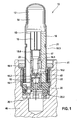
- an embodiment of a valve cartridge 10 for a solenoid valve comprises a capsule 12, a magnet armature 14 movably guided inside the capsule 12, a valve insert 18 according to the invention, which is inserted with a first end into the capsule 12 and subsequently with reference to FIG Fig. 2 to 4 will be described in detail, and a valve body 19 with a main valve seat 19.1.
- a plunger 16 is longitudinally movably guided, which has a closing element 16.1 with a sealing element 16.2, which dips sealingly into the main valve seat 19.1 of the valve body 19 for performing a sealing function.
- the plunger 16 can be moved by the armature 14 against the force of a return spring 17 within the valve core 18, wherein the armature 14 is moved by a magnetic force which is generated by a magnetic assembly, not shown.
- the capsule 12 is designed as a valve component that seals towards the atmosphere in the direction of the caulking region 41 with a fluid block 40 extended. Therefore, the caulking are not absorbed by the valve core 18, but by a Verstemmbuchse 18.1.
- a maximum stroke of the plunger 16 can be adjusted by an axial displacement of the valve insert 18 within the capsule 12.
- a minimum air gap 15 between the armature 14 and the valve core 18 can be adjusted by axially displacing the valve body 19 within the valve core 18 with the armature 14 in place.
- the set air gap 15 can be defined by a crimp connection 21 between the capsule 12 and the valve core 18, wherein the valve core 18 can be designed to produce the crimp 21 with a circumferential groove 18.3.
- the return spring 17 for the plunger 16 is arranged outside the flow region, wherein the return spring 17 is supported on a spring support 23, which is designed in the illustrated embodiment as inserted into the valve core 18 clamping sleeve.
- the valve body 19 is designed as a hood-shaped sleeve.
- the valve body 19 embodied as a sleeve is designed, for example, as a deep-drawn part and is pressed over a press-fit area into a second end of the valve insert 18 designed as a slotted sleeve such that the main valve seat 19.1 is arranged inside the valve insert 18.
- the main valve seat 19.1 in the valve body 19 is decoupled from the press-fit region in order to prevent deformation of the main valve seat 19.1 due to the press-fitting process of the valve body 19 into the valve core 18.
- the hydraulic forces are absorbed by the valve insert 18 designed as a slotted sleeve.
- the pressed-on reinforcing ring 22 advantageously increases the structural strength of the valve insert 18 when the valve body 19 is pressed in.
- the joints of the valve insert 18 designed as a slotted sleeve can be connected to one another at least at the second end of the valve insert 18, to increase the structural strength of the valve core 18 during the pressing of the valve body 19.
- the joints of the valve insert 18 designed as a slotted sleeve can be connected to one another by welding and / or gluing and / or toothing, for example.
- a designed as a plastic insert valve body 20 is axially applied to the valve insert 18 and supported, wherein the valve body 20 is sealingly inserted through a dome in an interior of the valve body 19 and seals with the outer contour against the surrounding fluid block 40.
- the illustrated valve body 20 includes an eccentrically arranged check valve 20.1, which performs a directional flow function.
- the valve body 20 receives a flat filter 20.2.
- the valve insert 18 is designed as a one-piece slotted sleeve, which comprises three symmetrically arranged on the circumference, lying transverse to the valve insert 19 radial bores 18.2 as outflow and the inner bore 18.4 as an inflow.
- the radial bores 18. 2 have the function of permitting a specific fluid volume flow 42 in an open valve state as a function of the design and operating point of the solenoid valve.
- the inner bore 18.4 of the valve core 18 has a nearly perfect or very closely approximated circular shape, in which the plunger 16 is guided.
- the fluid flow 42 flows through the main valve seat 19. 1 and the outflow openings designed as radial bores 18. 2.
- the shape of the radial bores 18.2 influences the flow characteristics.
- the radial bores 18. 2 are each formed with a trumpet-shaped geometry in order to influence the flow characteristic of the fluid stream 42 in a targeted manner.
- an effective cross-section of the respective radial bore 18.2 in the direction of the fluid flow 42 in an inflow region 18.5 is narrowed to a constriction 18.7 and expanded in an outflow region 18.6 starting from the constriction 18.7. Since a length of the inflow region 18.5 to the constriction 18.7 is shorter than the length of the outflow region 18.6 starting from the constriction 18.7, the fluid flow 42 is accelerated from a low first velocity V 1 to a higher second velocity V 2 .
- the length of the inflow to the bottleneck longer than the length of Ausström Schemes be executed from the bottleneck, whereby the flow is braked by the compression shock and depending on the valve application, a delayed pressure build-up or Pressure reduction can be achieved. Due to the trumpet-shaped geometry, the radial bores 18.2 are approximated to the shape of a Laval nozzle. Thus, the fluid flow can be accelerated or decelerated, without causing excessive compression shocks.
- valve insert 18 By changing the flow velocity within the radial bores 18.2, a negative pressure can be generated, so that any air or gas bubbles formed within the solenoid valve due to the resulting pressure difference through the radial bores 18.2 are discharged from the valve. Due to the improved flow control behavior, the valve acoustics can be positively influenced as a result of the change in flow velocity within the generated trumpet shape in the radial bores 18.2.
- Embodiments of the valve insert 18 according to the invention enable a reduction or elimination of the vibrations and noises resulting from the possible outgassing of the air / gas bubbles formed during operation and improve the self-venting property of a hydraulic solenoid valve.
- the fluid flow guidance by a corresponding design of the trumpet-shaped geometry of the individual radial bores 18.2 in hydraulic and / or pneumatic solenoid valves, for example by influencing the flow resistance or the flow (laminar / turbulent) or by a fluid compression shock to increase pressure before the radial bore 18.2 or by a fluid expansion (Laval nozzle principle) for Generation of a pressure drop after the radial bore 18.2 optimized and the solenoid valve acoustics are improved.
- the designed as a one-piece slotted sleeve valve insert 18 can be prepared for example by rolling a metal strip 18 ', as described below with reference to Fig. 5 to 7 is described.
- At least one axially extending volume compensation groove is incorporated into the plunger 16.
- the at least one volume compensation groove can also be incorporated into the inner bore of the valve insert 18.
- Fig. 5 to 7 It can be seen that for the production of the valve insert 18 according to the invention in a metal strip 18 'at least one bore 18.2 is introduced with a corresponding drilling tool 50.
- at least one edge region of the at least one bore 18.2 is formed to form an inflow region 18.5 and / or an outflow region 18.6 as a function of a desired flow characteristic of the at least one bore 18.2 by an embossing and / or machining process with a corresponding one Embossing and / or cutting tool 52 formed.
- a chamfer or a rounding with a predetermined depth can be applied to the bore edges to form the inflow region 18.5 and / or the outflow region 18.6.
- the sheet-metal strip 18 ' can be deformed both on one side and on both sides in the region of the at least one bore 18.2 as a function of the desired trumpet-shaped geometry of the at least one bore 18.2.
- the sheet metal strip 18 ' is transformed by a forming process to the one-piece slotted sleeve 18, which has at least one radial bore 18.2 with a trumpet-shaped geometry.
- the forming operation can be carried out by means of corresponding tools 54, for example by bending or rolling the sheet metal strip 18 '.
- Embodiments of the invention advantageously allow the targeted influencing of the fluid flow behavior or the fluid flow behavior by forming a radial bore in the valve core in the form of a "trumpet" by means of punching, cutting, drilling or punching, by means of embossing and / or chamfering a Kantenfase or edge rounding and by means of the subsequent forming by bending or rolling the metal strip.
- the advantages of the invention lie in the improved venting property, in the improved vibration behavior, in the improved acoustics of the solenoid valve and in an optimized solenoid valve function by the trumpet-shaped geometry of the radial bores according to the invention.
Landscapes
- Engineering & Computer Science (AREA)
- Physics & Mathematics (AREA)
- Electromagnetism (AREA)
- Mechanical Engineering (AREA)
- General Engineering & Computer Science (AREA)
- Fluid Mechanics (AREA)
- Transportation (AREA)
- Magnetically Actuated Valves (AREA)
- Valves And Accessory Devices For Braking Systems (AREA)
- Valve Housings (AREA)
Description
- Die Erfindung betrifft einen Ventileinsatz für eine Ventilpatrone nach der Gattung des unabhängigen Patentanspruchs 1, sowie eine zugehörige Ventilpatrone für ein Magnetventil, ein zugehöriges Magnetventil und ein Verfahren zur Herstellung eines Ventileinsatzes nach der Gattung des unabhängigen Patentanspruchs 6.
- Aus dem Stand der Technik sind Magnetventile, insbesondere für Hydraulikaggregate bekannt, die beispielsweise in einem Antiblockiersystem (ABS) oder einem Antriebsschlupfregelsystem (ASR-System) oder einem elektronischen Stabilitätsprogrammsystem (ESP-System) eingesetzt werden können. Ein Magnetventil als technisches Bauteil dient dazu, den Ein- oder Auslass von Gasen oder Flüssigkeiten zu kontrollieren oder die Fließrichtung zu steuern bzw. zu regeln.
- In der Offenlegungsschrift
DE 10 2007 053 134 A1 werden beispielsweise eine Ventilpatrone für ein Magnetventil und ein zugehöriges Magnetventil mit einer solchen Ventilpatrone beschrieben. Die beschriebene Ventilpatrone umfasst eine Kapsel, einen innerhalb der Kapsel beweglich geführten Magnetanker, einen Ventileinsatz, der mit einem ersten Ende in die Kapsel eingeschoben ist und einen Ventilkörper, der in ein zweites Ende des Ventileinsatzes eingepresst ist und einen Hauptventilsitz aufweist. Der von einer erzeugten Magnetkraft bewegte Magnetanker bewegt einen innerhalb des Ventileinsatzes geführten Stößel, der ein Schließelement mit einem Dichtelement aufweist, wobei das Dichtelement zur Ausführung einer Dichtfunktion dichtend in den Hauptventilsitz des Ventilkörpers eintaucht. Hierbei ist der Ventileinsatz als einteilige geschlitzte Hülse ausgeführt, und der Ventilkörper ist als haubenförmige Hülse ausgeführt. Der als Hülse ausgeführte Ventilköper ist so in ein zweites Ende des als geschlitzte Hülse ausgeführten Ventileinsatzes eingepresst, dass der Hauptventilsitz innerhalb des Ventileinsatzes angeordnet ist. Der als einteilige geschlitzte Hülse ausgeführte Ventileinsatz kann beispielsweise durch Einrollen eines Blechstreifens hergestellt werden, und der Ventilkörper kann beispielsweise als haubenförmiges Tiefziehteil hergestellt werden. In Ausgestaltung der Ventilpatrone kann eine spätere Form einer Innenbohrung des Ventileinsatzes vor dem Einrollen in eine korrespondierende Oberfläche des Blechstreifens eingebracht werden. Dies ermöglicht, dass beliebige günstige Formen für eine Volumenausgleichsnut durch einfache Bearbeitung der korrespondierenden Oberfläche des Blechstreifens vor dem Einrollen eingearbeitet werden können. Der Ventileinsatz des Magnetventils besitzt eine oder mehrere als Zu- bzw. Abströmöffnungen ausgeführt Radialbohrungen. Diese Bohrungen haben die Funktion, in einem geöffneten Ventilzustand einen bestimmten Volumenstrom, je nach Auslegung und Arbeitspunkt des Magnetventils, durchzulassen. Für die Durchflussmenge ist die Bohrungsquerschnittsgröße von wesentlicher Bedeutung. - Im Patent
US 3,776, 278 wird ein manuelles Gasventil mit einem Ventileinsatz beschrieben, welcher als einteilige Hülse ausgeführt ist, welche Längsschlitze oder Radialbohrungen als Zu- oder Abströmungsöffnung eines Fluidstroms aufweist. - In der Offenlegungsschrift
WO 02/090806 - Der erfindungsgemäße Ventileinsatz für eine Ventilpatrone eines Magnetventils mit den Merkmalen des unabhängigen Patentanspruchs 1 hat demgegenüber den Vorteil, dass mindestens eine als Radialbohrung ausgeführte Zu- und/oder Abströmungsöffnung des Ventileinsatzes für einen Fluidstrom mit einer trompetenförmigen Geometrie ausgebildet ist, um die Strömungscharakteristik des Fluidstroms gezielt zu beeinflussen. Hierbei ist der Ventileinsatz als einteilige geschlitzte Hülse aus einem Blechstreifen hergestellt.
- Erfindungsgemäß ist ein wirksamer Querschnitt der mindestens einen Radialbohrung in Richtung des Fluidstroms in einem Einströmbereich bis zu einer Engstelle kontinuierlich verengt und in einem Ausströmbereich ausgehend von der Engstelle kontinuierlich aufgeweitet. Die Form der Radialbohrung beeinflusst die Strömungscharakteristik, so dass die trompetenförmige Geometrie der als Zu- bzw. Abströmöffnung ausgeführten Radialbohrung geometrisch an die Form einer Lavaldüse angenähert wird. Aufgrund des verbesserten Strömungsführungsverhaltens kann die Ventilakustik, infolge der Änderung der Strömungsgeschwindigkeit innerhalb der erzeugten trompetenförmigen Geometrie in der als Zu- bzw. Abströmöffnung ausgeführten Radialbohrung positiv beeinflusst werden.
- Der erfindungsgemäße Ventileinsatz kann in einer Ventilpatrone bzw. einem Magnetventil eingesetzt werden, um die Fluidströmungscharakteristik in vorteilhafter Weise gezielt zu beeinflussen.
- Das erfindungsgemäße Verfahren zur Herstellung eines Ventileinsatzes für eine Ventilpatrone eines Magnetventils mit den Merkmalen des unabhängigen Patentanspruchs 6 hat demgegenüber den Vorteil, dass in einen Blechstreifen mindestens eine Bohrung eingebracht wird, und mindestens ein Randbereich der mindestens einen Bohrung in Abhängigkeit von einer gewünschten Strömungscharakteristik durch einen Präge- und/oder Zerspanvorgang so umgeformt wird, dass nach einem Umformungsvorgang des Blechstreifens zur geschlitzten Hülse für die mindestens eine Bohrung eine trompetenförmige Geometrie ausgebildet wird.
- Durch Ausführungsformen der Erfindung ist die gezielte Beeinflussung der Fluidströmungsführung bzw. des Fluidströmungsverhaltens durch Erzeugung einer Radialbohrung im Ventileinsatz mit einer trompetenförmigen Geometrie möglich, die eine Ähnlichkeit zur Form einer Lavaldüse aufweist. Die trompetenförmige Geometrie der Radialbohrung kann beispielsweise mittels Stanzen, Ausschneidens, Bohren oder Lochen, mit einer Prägung und/oder Zerspanung einer Kantenfase oder Kantenrundung der korrespondierenden Radialbohrung und durch das anschließende Umformen des Blechstreifens zur geschlitzten Hülse durch Biegen oder Rollieren o.ä. hergestellt werden. Durch Ausführungsformen der Erfindung kann die Qualität der Druckmodulation und die Akustik bei der Ausführung der zugeordneten Funktionen in vorteilhafter Weise verbessert werden. Bei einem hydraulischen Medium kann die Selbstentlüftungseigenschaft des korrespondierenden Magnetventils verbessert werden, wodurch durch Ausgasen von während des Betriebs gebildeten Luft-/Gasblasen entstehende Schwingungen und Geräusche reduziert bzw. eliminiert werden können. Allgemein kann bei hydraulischen und pneumatischen Magnetventilen die Fluidströmungsführung durch die erfindungsgemäße Beeinflussung des Strömungswiderstand und der Strömungsart sowie durch Erzeugen einer Drucksteigerung vor der Radialbohrung bzw. eines Druckabfalls nach der Radialbohrung optimiert und die Magnetventilakustik verbessert werden. Zusammenfassend liegen die Vorteile der Erfindung in der verbesserten Entlüftungseigenschaft, im verbesserten Schwingungsverhalten, in der verbesserten Akustik des Magnetventils sowie in einer optimierten Magnetventilfunktion durch die trompetenförmige Geometrie der als Radialbohrungen ausgeführten Zu- bzw. Abströmöffnungen.
- Durch die in den abhängigen Ansprüchen aufgeführten Maßnahmen und Weiterbildungen sind vorteilhafte Verbesserungen des im unabhängigen Patentanspruch 1 angegebenen Ventileinsatzes und des im unabhängigen Patentanspruch 6 angegebenen Verfahren zur Herstellung eines Ventileinsatzes möglich.
- In Ausgestaltung des erfindungsgemäßen Ventileinsatz ist eine Länge des Einströmbereichs bis zur Engstelle kürzer als die Länge des Ausströmbereichs ausgehend von der Engstelle ausgeführt, um den Fluidstrom zu beschleunigen, ohne dass es zu starken Verdichtungsstößen kommt. Alternativ ist eine Länge des Einströmbereichs bis zur Engstelle länger als die Länge des Ausströmbereichs ausgehend von der Engstelle ausgeführt, um den Fluidstrom abzubremsen. Im Fall der erwünschten Fluidströmungsverzögerung kann die Fluidströmung durch den Verdichtungsstoß gebremst werden und in Abhängigkeit von der Ventilanwendung kann ein verzögerter Druckaufbau oder Druckabbau erzielt werden. Durch die Änderung der Strömungsgeschwindigkeit innerhalb der als Zu- bzw. Abströmöffnung ausgeführten Radialbohrung kann ein Unterdruck so erzeugt werden, dass eventuell gebildete Luft- bzw. Gasblasen im Magnetventil infolge der daraus resultierenden Druckdifferenz durch die Radialbohrungen aus dem Magnetventil abgeführt werden.
- In Ausgestaltung des erfindungsgemäßen Verfahrens werden Art und/oder Parameter zum Einbringen der mindestens einen Bohrung in den Blechstreifen in Abhängigkeit von der zu erzeugenden trompetenförmigen Geometrie der mindestens einen Bohrung durch eine ausgewählte Werkzeugform bestimmt. Die mindestens eine Bohrung kann beispielsweise durch Stanzen, Lochen, Ausschneiden oder Bohren in den Blechstreifen eingebracht werden, wobei durch die Geometrie des verwendeten Werkzeugs für die mindestens eine Bohrung beispielsweise eine gerade, ovale, konische usw. Form vorgegeben werden kann.
- In weiterer Ausgestaltung des erfindungsgemäßen Verfahrens werden Art und/oder Parameter des Präge- und/oder Zerspanvorgangs in Abhängigkeit von der zu erzeugenden trompetenförmigen Geometrie der mindestens einen Bohrung durch eine ausgewählte Werkzeugform bestimmt. In Abhängigkeit von der Auslegung der gewünschten trompetenförmigen Geometrie der mindestens einen Bohrung können die Prägungs- und/oder Zerspanungstiefe und/oder die Prägungs- und/oder Zerspanungsform vorgegeben werden. So kann durch den Präge- und/oder Zerspanvorgang beispielsweise eine Fase oder eine Rundung an den Bohrungskantenbereichen angebracht werden. Hierbei kann der Blechstreifen im Bereich der Bohrung je nach Variante der Trompetenform sowohl einseitig als auch beidseitig umgeformt werden.
- In weiterer Ausgestaltung des erfindungsgemäßen Verfahrens werden Art und Parameter des Umformvorgangs zur geschlitzten Hülse in Abhängigkeit von der zu erzeugenden trompetenförmigen Geometrie der mindestens einen Bohrung durch eine ausgewählte Werkzeugform bestimmt. Die Umformung des Blechstreifens zur geschlitzten Hülse kann beispielsweise durch Rollieren oder Umbiegen o.ä. erzeugt werden.
- Zusammenfassend können durch entsprechende Werkzeugformen nahezu beliebige Variationen der Trompetenform für die mindestens eine Radialbohrung im Ventileinsatz des Magnetventils gezielt erzeugt werden, um die Fluidströmung gezielt zu beeinflussen.
- Der erfindungsgemäße Ventileinsatz mit mindestens einer trompetenförmigen Radialbohrung, kann beispielsweise in stromlos offenen oder geschlossenen Magnetventilen verwendet werden.
- Vorteilhafte Ausführungsformen der Erfindung sind in den Zeichnungen dargestellt und werden nachfolgend beschrieben. In den Zeichnungen bezeichnen gleiche Bezugszeichen Komponenten bzw. Elemente, die gleiche bzw. analoge Funktionen ausführen.
-
-
Fig. 1 zeigt eine schematische Schnittdarstellung eines Ausführungsbeispiels einer erfindungsgemäßen Ventilpatrone für ein Magnetventil. -
Fig. 2 zeigt eine schematische Perspektivdarstellung eines erfindungsgemäßen Ventileinsatzes für die Ventilpatrone gemäßFig. 1 . -
Fig. 3 zeigt eine schematische Querschnittdarstellung des Ventileinsatzes gemäßFig. 2 . -
Fig. 4 zeigt eine schematische Darstellung eines Details ausFig. 3 . -
Fig. 5 bis 7 zeigen verschiedene Stufen eines Ausführungsbeispiels eines Verfahrens zur Herstellung des Ventileinsatzes gemäßFig. 1 bis 4 für die Ventilpatrone gemäßFig. 1 . - Wie aus
Fig. 1 ersichtlich ist, umfasst ein Ausführungsbeispiel einer erfindungsgemäßen Ventilpatrone 10 für ein Magnetventil eine Kapsel 12, einen innerhalb der Kapsel 12 beweglich geführten Magnetanker 14, einen erfindungsgemäßen Ventileinsatz 18, der mit einem ersten Ende in die Kapsel 12 eingeschoben ist und nachfolgend unter Bezugnahme aufFig. 2 bis 4 im Detail beschrieben wird, und einen Ventilkörper 19 mit einem Hauptventilsitz 19.1. Innerhalb des Ventileinsatzes 18 ist ein Stößel 16 längsbeweglich geführt, der ein Schließelement 16.1 mit einem Dichtelement 16.2 aufweist, das zur Ausführung einer Dichtfunktion dichtend in den Hauptventilsitz 19.1 des Ventilkörpers 19 eintaucht. Der Stößel 16 kann von dem Magnetanker 14 gegen die Kraft einer Rückstellfeder 17 innerhalb des Ventileinsatzes 18 bewegt werden, wobei der Magnetanker 14 von einer Magnetkraft bewegt wird, die von einer nicht dargestellten Magnetbaugruppe erzeugt wird. - Wie aus
Fig. 1 weiter ersichtlich ist, ist die Kapsel 12 als zur Atmosphäre hin dichtendes Ventilbauteil in Richtung Verstemmbereich 41 mit einem Fluidblock 40 verlängert ausgeführt. Daher werden die Verstemmkräfte nicht vom Ventileinsatz 18, sondern von einer Verstemmbuchse 18.1 aufgenommen. Im dargestellten Ausführungsbeispiel der erfindungsgemäßen Ventilpatrone kann ein maximaler Hub des Stößels 16 durch ein axiales Verschieben des Ventileinsatzes 18 innerhalb der Kapsel 12 eingestellt werden. Ein minimaler Luftspalt 15 zwischen dem Magnetanker 14 und dem Ventileinsatz 18 kann durch axiales Verschieben des Ventilkörpers 19 innerhalb des Ventileinsatzes 18 mit eingelegtem Anker 14 eingestellt werden. Der eingestellte Luftspalt 15 kann durch eine Crimpverbindung 21 zwischen der Kapsel 12 und dem Ventileinsatz 18 festgelegt werden, wobei der Ventileinsatz 18 zur Herstellung der Crimpverbindung 21 mit einer umlaufenden Nut 18.3 ausgeführt werden kann. Somit wird durch die Crimpverbindung 21 sichergestellt, dass der Arbeitsluftspalt 15 erhalten bleibt, wobei zusätzlich die hydraulisch wirkenden Kräfte aufgenommen werden können. Die Rückstellfeder 17 für den Stößel 16 ist außerhalb des Strömungsbereichs angeordnet, wobei sich die Rückstellfeder 17 auf einer Federauflage 23 abstützt, die im dargestellten Ausführungsbeispiel als in den Ventileinsatz 18 eingeführte Spannhülse ausgeführt ist. Durch die Verlegung der Rückstellfeder 17 aus dem durchströmten Bauraum können der Verschleiß am Stößel 16 reduziert und der Durchfluss zwischen dem Hauptventilsitz 19.1 und entsprechenden in den Ventileinsatz 18 eingebrachten Radialbohrungen 18.2 erhöht werden. - Wie aus
Fig. 1 weiter ersichtlich ist, ist der Ventilkörper 19 als haubenförmige Hülse ausgeführt. Der als Hülse ausgeführte Ventilköper 19 ist beispielsweise als Tiefziehteil ausgeführt und wird über einem Einpressbereich so in ein zweites Ende des als geschlitzte Hülse ausgeführten Ventileinsatzes 18 eingepresst, dass der Hauptventilsitz 19.1 innerhalb des Ventileinsatzes 18 angeordnet ist. Über einen Entkoppelbereich ist der Hauptventilsitz 19.1 im Ventilkörper 19 vom Einpressbereich entkoppelt, um eine Verformung des Hauptventilsitzes 19.1 durch den Einpressvorgang des Ventilkörpers 19 in den Ventileinsatz 18 zu verhindern. Die hydraulischen Kräfte werden von dem als geschlitzte Hülse ausgeführten Ventileinsatz 18 aufgenommen. Um ein Aufweiten des Ventileinsatzes 18 durch das Einpressen des Ventilkörpers 19 zu verhindern, ist im dargestellten Ausführungsbeispiel ein Armierungsring 22 auf das zweite Ende des Ventileinsatzes 18 aufgepresst. Der aufgepresste Armierungsring 22 vergrößert in vorteilhafter Weise die Gestaltfestigkeit des Ventileinsatzes 18 beim Einpressen des Ventilkörpers 19. Bei einer alternativen nicht dargestellten Ausführungsform der erfindungsgemäßen Ventilpatrone 10 können die Stöße des als geschlitzte Hülse ausführten Ventileinsatzes 18 mindestens am zweiten Ende des Ventileinsatzes 18 miteinander verbunden werden, um die Gestaltfestigkeit des Ventileinsatzes 18 beim Einpressen des Ventilkörpers 19 zu vergrößern. Die Stöße des als geschlitzte Hülse ausgeführten Ventileinsatzes 18 können beispielsweise durch Schweißen und/oder Kleben und/oder Verzahnen miteinander verbunden werden. - Wie weiter aus
Figur 1 ersichtlich ist, ist ein als Kunststoffeinsatz ausgeführtes Ventilunterteil 20 axial an den Ventileinsatz 18 angelegt und abgestützt, wobei das Ventilunterteil 20 über einen Dom dichtend in einen Innenraum des Ventilkörpers 19 eingeschoben ist und mit der Außenkontur gegen den umgebenden Fluidblock 40 abdichtet. Zudem umfasst das dargestellte Ventilunterteil 20 ein exzentrisch angeordnetes Rückschlagventil 20.1, das eine richtungsorientierte Durchflussfunktion ausführt. Zusätzlich nimmt das Ventilunterteil 20 einen Flachfilter 20.2 auf. - Wie aus
Fig. 1 bis 4 ersichtlich ist, ist der Ventileinsatz 18 als einteilige geschlitzte Hülse ausgeführt, welche drei symmetrisch am Umfang angeordnete, quer zum Ventileinsatz 19 liegende Radialbohrungen 18.2 als Abströmöffnungen und die Innenbohrung 18.4 als Zuströmöffnung umfasst. Die Radialbohrungen 18.2 haben die Funktion, in einem geöffneten Ventilzustand einen bestimmten Fluidvolumenstrom 42 in Abhängigkeit von der Auslegung und vom Arbeitspunkt des Magnetventils durchzulassen. Im dargestellten Ausführungsbeispiel weist die Innenbohrung 18.4 des Ventileinsatzes 18 eine nahezu vollkommene oder sehr stark angenäherte Kreisform auf, in welcher der Stößel 16 geführt wird. Im geöffneten Magnetventilzustand fließt die Fluidströmung 42 durch den Hauptventilsitz 19.1 und die als Radialbohrungen 18.2 ausgeführten Abströmöffnungen. Hierbei beeinflusst die Form der Radialbohrungen 18.2 die Strömungscharakteristik. Erfindungsgemäß sind die Radialbohrungen 18.2 jeweils mit einer trompetenförmigen Geometrie ausgebildet, um die Strömungscharakteristik des Fluidstroms 42 gezielt zu beeinflussen. - Wie Aus
Fig. 3 und 4 weiter ersichtlich ist, ist ein wirksamer Querschnitt der jeweiligen Radialbohrung 18.2 in Richtung des Fluidstroms 42 in einem Einströmbereich 18.5 bis zu einer Engstelle 18.7 verengt und in einem Ausströmbereich 18.6 ausgehend von der Engstelle 18.7 aufgeweitet. Da eine Länge des Einströmbereichs 18.5 bis zur Engstelle 18.7 kürzer als die Länge des Ausströmbereichs 18.6 ausgehend von der Engstelle 18.7 ausgeführt ist, wird der Fluidstrom 42 von einer niedrigen ersten Geschwindigkeit V1 auf eine höhere zweite Geschwindigkeit V2 beschleunigt. Um den Fluidstrom 42 abzubremsen kann bei einer alternativen nicht dargestellten Ausführungsform die Länge des Einströmbereichs bis zur Engstelle länger als die Länge des Ausströmbereichs ausgehend von der Engstelle ausgeführt werden, wodurch die Strömung durch den Verdichtungsstoß gebremst wird und in Abhängigkeit von der Ventilanwendung ein verzögerter Druckaufbau oder Druckabbau erzielt werden kann. Durch die trompetenförmige Geometrie sind die Radialbohrungen 18.2 an die Form einer Lavaldüse angenähert. Somit kann die Fluidströmung beschleunigt oder abgebremst werden, ohne dass es zu starken Verdichtungsstößen kommt. - Durch die Änderung der Strömungsgeschwindigkeit innerhalb der Radialbohrungen 18.2 kann ein Unterdruck erzeugt werden, so dass eventuell innerhalb des Magnetventils gebildete Luft bzw. Gasblasen infolge der resultierenden Druckdifferenz durch die Radialbohrungen 18.2 aus dem Ventil abgeführt werden. Aufgrund des verbesserten Strömungsführungsverhaltens kann die Ventilakustik, infolge der Änderung der Strömungsgeschwindigkeit innerhalb der erzeugten Trompetenform in den Radialbohrungen 18.2 positiv beeinflusst werden. Ausführungsformen des erfindungsgemäßen Ventileinsatzes 18 ermöglichen eine Reduzierung bzw. Eliminierung der durch das mögliche Ausgasen der im Betrieb gebildeten Luft-/Gasblasen entstehenden Schwingungen und Geräusche und verbessern die Selbstentlüftungseigenschaft eines hydraulischen Magnetventils. Zudem kann die Fluidströmungsführung durch eine entsprechende Ausbildung der trompetenförmigen Geometrie der einzelnen Radialbohrungen 18.2 bei hydraulischen und/oder pneumatischen Magnetventilen beispielsweise durch eine Beeinflussung des Strömungswiderstands oder der Strömungsart (laminar/turbulent) oder durch einen Fluidverdichtungsstoß zur Drucksteigerung vor der Radialbohrung 18.2 oder durch eine Fluidexpansion (Lavaldüsen-Prinzip) zur Erzeugung eines Druckabfalls nach der Radialbohrung 18.2 optimiert und die Magnetventilakustik verbessert werden.
- Der als einteilige geschlitzte Hülse ausgeführte Ventileinsatz 18 kann beispielsweise durch Einrollen eines Blechstreifens 18' hergestellt werden, wie nachfolgend unter Bezugnahme auf
Fig. 5 bis 7 beschrieben wird. Zum Ausgleich des Volumens, das der Stößel 16 bei seiner durch den von der Magnetbaugruppe eingeleiteten Magnetfluss bewirkten Axialbewegung verdrängt, und zur Entlüftung bzw. Befüllung, ist in den Stößel 16 mindestens eine axial verlaufende Volumenausgleichsnut eingearbeitet. Alternativ kann die mindestens eine Volumenausgleichsnut jedoch auch in die Innenbohrung des Ventileinsatzes 18 eingearbeitet werden. - Wie aus
Fig. 5 bis 7 ersichtlich ist wird zur Herstellung des erfindungsgemäßen Ventileinsatzes 18 in einen Blechstreifen 18' mindestens eine Bohrung 18.2 mit einem entsprechenden Bohrwerkzeug 50 eingebracht. Die mindestens eine Bohrung 18.2 kann beispielsweise durch Stanzen, Lochen, Ausschneiden oder Bohren in den Blechstreifen 18' eingebracht werden. Nach dem Einbringen der mindestens einen Bohrung 18.2 wird mindestens ein Randbereich der mindestens einen Bohrung 18.2 zur Bildung eines Einströmbereichs 18.5 und/oder eines Ausströmbereichs 18.6 in Abhängigkeit von einer gewünschten Strömungscharakteristik der mindestens einen Bohrung 18.2 durch einen Präge- und/oder Zerspanvorgang mit einem entsprechenden Präge- und/oder Zerspanwerkzeug 52 umgeformt. Durch den Präge- und/oder Zerspanvorgang kann beispielsweise eine Fase oder eine Rundung mit einer vorgegebenen Tiefe auf die Bohrungskanten zur Bildung des Einströmbereichs 18.5 und/oder des Ausströmbereichs 18.6 angebracht werden. Der Blechstreifen 18' kann im Bereich der mindestens einen Bohrung 18.2 in Abhängigkeit von der gewünschten trompetenförmigen Geometrie der mindestens einen Bohrung 18.2 sowohl einseitig als auch beidseitig umgeformt werden. Anschließend wird der Blechstreifen 18' durch einen Umformungsvorgang zur einteiligen geschlitzten Hülse 18 umgeformt, die mindestens eine Radialbohrung 18.2 mit einer trompetenförmigen Geometrie aufweist. Der Umformungsvorgang kann mittels entsprechenden Werkzeugen 54 beispielsweise durch Biegen oder Rollieren des Blechstreifen 18' ausgeführt werden. - Durch die gerade, ovale, konische Form des Werkzeugs zum Einbringen der mindestens einen Bohrung 18.2 in den Blechstreifen 18', durch die Form und Tiefe der Prägung und/oder Zerspanung wie auch durch die Art und Parameter des Umformverfahrens können nahezu beliebige Variationen der Trompetenform der mindestens einen Radialbohrung 18.2 am Ventileinsatz 18 der Ventilpatrone 10 des Magnetventils gezielt erzeugt werden.
- Ausführungsformen der Erfindung ermöglichen in vorteilhafter Weise die gezielte Beeinflussung der Fluidströmungsführung bzw. des Fluidströmungsverhaltens durch die Ausbildung einer Radialbohrung im Ventileinsatz in Form einer "Trompete" mittels Stanzen, Ausschneiden, Bohren oder Lochen, mittels der Prägung und/oder Zerspanung einer Kantenfase oder Kantenrundung und mittels des anschließenden Umformens durch Biegen oder Rollieren des Blechstreifens. Die Vorteile der Erfindung liegen in den verbesserten Entlüftungseigenschaft, im verbesserten Schwingverhalten, in der verbesserten Akustik des Magnetventils sowie in einer optimierten Magnetventilsfunktion durch die erfindungsgemäße trompetenförmige Geometrie der Radialbohrungen.
Claims (9)
- Ventileinsatz (18) für eine Ventilpatrone eines Magnetventils, wobei der Ventileinsatz (18) als einteilige geschlitzte Hülse aus einem Blechstreifen hergestellt ist und mindestens eine Radialbohrung (18.2) als Zu- oder Abströmungsöffnung eines Fluidstroms (42) aufweist, dadurch gekennzeichnet, dass die mindestens eine Radialbohrung (18.2) mit einer trompetenförmigen Geometrie ausgebildet ist, um die Strömungscharakteristik des Fluidstroms (42) gezielt zu beeinflussen, wobei der wirksame Querschnitt der mindestens einen Radialbohrung (18.2) in Richtung des Fluidstroms (42) in einem Einströmbereich (18.5) bis zu einer Engstelle (18.7) kontinuierlich verengt und in einem Ausströmbereich (18.6) ausgehend von der Engstelle (18.7) kontinuierlich aufgeweitet ist.
- Ventileinsatz (18) nach Anspruch 1, dadurch gekennzeichnet, dass eine Länge des Einströmbereichs (18.5) bis zur Engstelle (18.7) kürzer als die Länge des Ausströmbereichs (18.6) ausgehend von der Engstelle (18.7) ausgeführt ist, um den Fluidstrom (42) zu beschleunigen.
- Ventileinsatz (18) nach Anspruch 1, dadurch gekennzeichnet, dass eine Länge des Einströmbereichs (18.5) bis zur Engstelle (18.7) länger als die Länge des Ausströmbereichs (18.6) ausgehend von der Engstelle (18.7) ausgeführt ist, um den Fluidstrom (42) abzubremsen.
- Ventilpatrone (10) für ein Magnetventil mit einer Kapsel (12), einem innerhalb der Kapsel (12) beweglich geführten Magnetanker (14), einem Ventileinsatz (18), der mit einem ersten Ende in die Kapsel (12) eingeschoben ist und als einteilige geschlitzte Hülse mit mindestens einer Radialbohrung (18.2) als Zu- und/oder Abströmungsöffnung eines Fluidstroms (42) ausgeführt ist, und einem Ventilkörper (19) mit einem Hauptventilsitz (19.1), wobei der von einer erzeugten Magnetkraft bewegte Magnetanker (14) einen innerhalb des Ventileinsatzes (18) geführten Stößel (16) bewegt, der ein Schließelement (16.1) mit einem Dichtelement (16.2) aufweist, und wobei das Dichtelement (16.2) zur Ausführung einer Dichtfunktion dichtend in den Hauptventilsitz (19.1) des Ventilkörpers (19) eintaucht, dadurch gekennzeichnet, dass der Ventileinsatz (18) nach einem der Ansprüche 1 bis 3 ausgeführt ist.
- Magnetventil gekennzeichnet durch eine Ventilpatrone (10) nach Anspruch 4.
- Verfahren zur Herstellung eines Ventileinsatzes (18) für eine Ventilpatrone eines Magnetventils, wobei in einen Blechstreifen (18') mindestens eine Bohrung (18.2) eingebracht wird und der Blechstreifen (18') anschießend zu einer einteiligen geschlitzten Hülse umgeformt wird, dadurch gekennzeichnet, dass mindestens ein Randbereich (18.5, 18.6) der mindestens einen Bohrung (18.2) in Abhängigkeit von einer gewünschten Strömungscharakteristik durch einen Präge- und/oder Zerspanvorgang umgeformt wird, um nach dem Umformungsvorgang zur geschlitzten Hülse die mindestens eine Bohrung (18.2) mit einer trompetenförmige Geometrie auszubilden, wobei der wirksame Querschnitt der mindestens einen Bohrung (18.2) in Richtung des Fluidstroms (42) in einem Einströmbereich (18.5) bis zu einer Engstelle (18.7) kontinuierlich verengt und in einem Ausströmbereich (18.6) ausgehend von der Engstelle (18.7) kontinuierlich aufgeweitet wird.
- Verfahren nach Anspruch 6, dadurch gekennzeichnet, dass Art und/oder Parameter zum Einbringen der mindestens einen Bohrung (18.2) in den Blechstreifen (18') in Abhängigkeit von der zu erzeugenden trompetenförmigen Geometrie der mindestens einen Bohrung (18.2) durch eine ausgewählte Werkzeugform bestimmt werden.
- Verfahren nach Anspruch 6 oder 7, dadurch gekennzeichnet, dass Art und/oder Parameter des Präge- und/oder Zerspanvorgangs in Abhängigkeit von der zu erzeugenden trompetenförmigen Geometrie der mindestens einen Bohrung (18.2) durch eine ausgewählte Werkzeugform bestimmt werden.
- Verfahren nach einem der Ansprüche 6 bis 8, dadurch gekennzeichnet, dass Art und Parameter des Umformvorgangs zur geschlitzten Hülse in Abhängigkeit von der zu erzeugenden trompetenförmigen Geometrie der mindestens einen Bohrung (18.2) durch eine ausgewählte Werkzeugform bestimmt werden.
Applications Claiming Priority (2)
| Application Number | Priority Date | Filing Date | Title |
|---|---|---|---|
| DE102009046202A DE102009046202A1 (de) | 2009-10-30 | 2009-10-30 | Ventileinsatz für eine Ventilpatrone, korrespondierende Ventilpatrone für ein Magnetventil und Verfahren zur Herstellung eines Ventileinsatzes |
| PCT/EP2010/063085 WO2011051036A1 (de) | 2009-10-30 | 2010-09-07 | Ventileinsatz für eine ventilpatrone, korrespondierende ventilpatrone für ein magnetventil, magnetventil mit einer derartigen ventilpatrone und verfahren zur herstellung eines ventileinsatzes |
Publications (2)
| Publication Number | Publication Date |
|---|---|
| EP2493734A1 EP2493734A1 (de) | 2012-09-05 |
| EP2493734B1 true EP2493734B1 (de) | 2015-02-25 |
Family
ID=42799799
Family Applications (1)
| Application Number | Title | Priority Date | Filing Date |
|---|---|---|---|
| EP10752789.7A Active EP2493734B1 (de) | 2009-10-30 | 2010-09-07 | Ventileinsatz für eine ventilpatrone, korrespondierende ventilpatrone für ein magnetventil, magnetventil mit einer derartigen ventilpatrone und verfahren zur herstellung eines ventileinsatzes |
Country Status (7)
| Country | Link |
|---|---|
| US (1) | US8979067B2 (de) |
| EP (1) | EP2493734B1 (de) |
| JP (1) | JP5710631B2 (de) |
| CN (1) | CN102596663B (de) |
| BR (1) | BR112012009768B1 (de) |
| DE (1) | DE102009046202A1 (de) |
| WO (1) | WO2011051036A1 (de) |
Families Citing this family (12)
| Publication number | Priority date | Publication date | Assignee | Title |
|---|---|---|---|---|
| DE102009046202A1 (de) | 2009-10-30 | 2011-05-19 | Robert Bosch Gmbh | Ventileinsatz für eine Ventilpatrone, korrespondierende Ventilpatrone für ein Magnetventil und Verfahren zur Herstellung eines Ventileinsatzes |
| DE102009055340A1 (de) * | 2009-12-28 | 2011-06-30 | Robert Bosch GmbH, 70469 | Ventilmodul, insbesondere Magnetventil für ein Bremssystem eines Kraftfahrzeugs, Verfahren zur Herstellung eines Ventilmoduls |
| DE102010062262A1 (de) * | 2010-12-01 | 2012-06-06 | Zf Friedrichshafen Ag | Aktuator für eine verstellbare Dämpfventileinrichtung |
| DE102011003924B4 (de) * | 2011-02-10 | 2015-01-08 | Zf Friedrichshafen Ag | Verstellbares Dämpfventil für einen Schwingungsdämpfer |
| JP5837000B2 (ja) * | 2013-05-24 | 2015-12-24 | 日信工業株式会社 | 車両用ブレーキ液圧制御装置および車両用ブレーキ液圧制御装置の製造方法 |
| JP2015009702A (ja) * | 2013-06-28 | 2015-01-19 | 株式会社デンソー | 車両用制動装置 |
| US20150130265A1 (en) * | 2013-11-12 | 2015-05-14 | Kelsey-Hayes Company | Solenoid Valve Having Hydraulic Damping Mechanism |
| KR101617802B1 (ko) * | 2014-10-30 | 2016-05-03 | 현대모비스 주식회사 | 감압 솔레노이드 밸브 |
| DE102016212561A1 (de) * | 2016-07-11 | 2018-01-11 | Robert Bosch Gmbh | Rückschlagventil für ein Magnetventil und zugehöriges Magnetventil |
| US10612684B2 (en) * | 2017-06-14 | 2020-04-07 | Bwi (Shanghai) Co., Ltd. | Electromagnetic valve assembly |
| DE102019214973B3 (de) * | 2019-09-30 | 2021-02-25 | Zf Friedrichshafen Ag | Verstellbare Dämpfventileinrichtung für einen Schwingungsdämpfer |
| DE102023208422A1 (de) * | 2023-09-01 | 2025-03-06 | Robert Bosch Gesellschaft mit beschränkter Haftung | Elektrisch ansteuerbares Magnetventil |
Family Cites Families (16)
| Publication number | Priority date | Publication date | Assignee | Title |
|---|---|---|---|---|
| US1049845A (en) * | 1910-09-15 | 1913-01-07 | Geissinger Regulator Company | Electromagnetic valve. |
| US1567043A (en) * | 1922-10-20 | 1925-12-29 | Zenith Carburateur Soc Du | Venturi and method of making the same |
| US2622618A (en) * | 1949-01-21 | 1952-12-23 | United Aircraft Prod | Electromagnetically controlled valve |
| US3776278A (en) * | 1971-06-29 | 1973-12-04 | Fisher Controls Co | Valve including noise reducing means |
| GB8700111D0 (en) | 1987-01-06 | 1987-02-11 | Scott R M | Fluid flow control valves |
| JPH083775Y2 (ja) * | 1988-09-14 | 1996-01-31 | エヌオーケー株式会社 | 流量制御弁 |
| US6024129A (en) * | 1998-07-16 | 2000-02-15 | Schima; Frank E. | Production efficient venturi insert |
| GB9817642D0 (en) | 1998-08-14 | 1998-10-07 | Kent Introl Ltd | A pressure reduction valve for a compressible fluid |
| US6536472B2 (en) | 2001-05-07 | 2003-03-25 | Fisher Controls International, Inc. | High performance fluid control valve |
| JP4316255B2 (ja) | 2003-02-24 | 2009-08-19 | 株式会社日立製作所 | 弁構造 |
| JP2004340260A (ja) * | 2003-05-15 | 2004-12-02 | Saginomiya Seisakusho Inc | 流量制御弁 |
| DE20312048U1 (de) | 2003-07-30 | 2003-12-18 | Südmo Holding GmbH | Schalldämpfer für Stellventile |
| JP4744459B2 (ja) * | 2007-02-14 | 2011-08-10 | 日信工業株式会社 | 常開型電磁弁 |
| JP4453732B2 (ja) * | 2007-09-14 | 2010-04-21 | 株式会社デンソー | 電磁弁 |
| DE102007053134A1 (de) | 2007-11-08 | 2009-05-14 | Robert Bosch Gmbh | Ventilpatrone für ein Magnetventil und zugehöriges Magnetventil |
| DE102009046202A1 (de) | 2009-10-30 | 2011-05-19 | Robert Bosch Gmbh | Ventileinsatz für eine Ventilpatrone, korrespondierende Ventilpatrone für ein Magnetventil und Verfahren zur Herstellung eines Ventileinsatzes |
-
2009
- 2009-10-30 DE DE102009046202A patent/DE102009046202A1/de not_active Ceased
-
2010
- 2010-09-07 JP JP2012535706A patent/JP5710631B2/ja active Active
- 2010-09-07 WO PCT/EP2010/063085 patent/WO2011051036A1/de not_active Ceased
- 2010-09-07 US US13/503,723 patent/US8979067B2/en active Active
- 2010-09-07 EP EP10752789.7A patent/EP2493734B1/de active Active
- 2010-09-07 BR BR112012009768-7A patent/BR112012009768B1/pt not_active IP Right Cessation
- 2010-09-07 CN CN201080048424.5A patent/CN102596663B/zh active Active
Also Published As
| Publication number | Publication date |
|---|---|
| JP5710631B2 (ja) | 2015-04-30 |
| US20120267555A1 (en) | 2012-10-25 |
| BR112012009768A8 (pt) | 2017-10-17 |
| CN102596663B (zh) | 2015-01-28 |
| EP2493734A1 (de) | 2012-09-05 |
| WO2011051036A1 (de) | 2011-05-05 |
| DE102009046202A1 (de) | 2011-05-19 |
| CN102596663A (zh) | 2012-07-18 |
| US8979067B2 (en) | 2015-03-17 |
| BR112012009768B1 (pt) | 2020-03-03 |
| BR112012009768A2 (pt) | 2016-05-17 |
| JP2013508651A (ja) | 2013-03-07 |
Similar Documents
| Publication | Publication Date | Title |
|---|---|---|
| WO2011051036A1 (de) | Ventileinsatz für eine ventilpatrone, korrespondierende ventilpatrone für ein magnetventil, magnetventil mit einer derartigen ventilpatrone und verfahren zur herstellung eines ventileinsatzes | |
| EP2219913B1 (de) | Ventilpatrone für ein magnetventil und zugehöriges magnetventil | |
| EP2091797B1 (de) | Magnetventil | |
| EP0951412B1 (de) | Magnetventil | |
| EP3206214B1 (de) | Elektromagneteinrichtung sowie fahrerassistenzeinrichtung | |
| EP3215771B1 (de) | Proportionalventil, klimakompressoranordnung sowie betriebsverfahren | |
| DE102009015584A1 (de) | Stoßdämpfer mit einstellbarer Dämpfungskraft | |
| DE102004030428A1 (de) | Ventilvorrichtung | |
| EP2170665B1 (de) | Magnetventil | |
| WO2008064942A1 (de) | Magnetventil | |
| DE102008020855A1 (de) | Elektromagnetventil, insbesondere für schlupfgeregelte Kraftfahrzeugbremsanlagen | |
| DE10047399A1 (de) | Elektromagnetventil, insbesondere für hydraulische Bremsanlagen mit Schlupfregelung | |
| WO2011079984A1 (de) | Ventilmodul, insbesondere magnetventil für ein bremssystem eines kraftfahrzeugs, verfahren zur herstellung eines derartigen ventilmoduls | |
| DE102015213840B4 (de) | Stromlos geschlossenes Magnetventil | |
| WO2009007277A1 (de) | Ventilpatrone für ein magnetventil | |
| WO1996029219A1 (de) | Elektromagnetventil mit druckbegrenzungsfunktion, insbesondere für hydraulische kraftfahrzeug-bremsanlagen mit schlupfregelung und/oder automatischem bremseneingriff zur fahrdynamikregelung | |
| EP1771675B1 (de) | Elektrisch ansteuerbares ventil | |
| DE102010063727B4 (de) | Magnetventil | |
| EP2519432A1 (de) | Magnetventil und verfahren zur herstellung eines derartigen magnetventils | |
| EP3529114B1 (de) | Magnetventil zur steuerung des bremsdrucks einer radbremse und werkzeug zur herstellung seines ventilelements | |
| DE102019120224A1 (de) | Ventil und Vorrichtung zur Regelung von Drücken eines Strömungsmittels mit dem Ventil sowie Vorrichtung zur Sicherung des Ventils in dem Getriebebauteil | |
| DE102019120226A1 (de) | Ventil und Vorrichtung zur Regelung von Drücken eines Strömungsmittels mit dem Ventil sowie Vorrichtung zur Sicherung des Ventils in dem Getriebebauteil | |
| EP1706301B1 (de) | Ventil zum steuern von fluiden mit integrierter druckausgleichsmöglichkeit | |
| DE19949222A1 (de) | Verfahren zur Einstellung eines Restluftspalts eines Magnetventils | |
| DE10044897A1 (de) | Verstemmstempel und Verstemmung |
Legal Events
| Date | Code | Title | Description |
|---|---|---|---|
| PUAI | Public reference made under article 153(3) epc to a published international application that has entered the european phase |
Free format text: ORIGINAL CODE: 0009012 |
|
| 17P | Request for examination filed |
Effective date: 20120530 |
|
| AK | Designated contracting states |
Kind code of ref document: A1 Designated state(s): AL AT BE BG CH CY CZ DE DK EE ES FI FR GB GR HR HU IE IS IT LI LT LU LV MC MK MT NL NO PL PT RO SE SI SK SM TR |
|
| DAX | Request for extension of the european patent (deleted) | ||
| GRAP | Despatch of communication of intention to grant a patent |
Free format text: ORIGINAL CODE: EPIDOSNIGR1 |
|
| INTG | Intention to grant announced |
Effective date: 20141126 |
|
| GRAS | Grant fee paid |
Free format text: ORIGINAL CODE: EPIDOSNIGR3 |
|
| GRAA | (expected) grant |
Free format text: ORIGINAL CODE: 0009210 |
|
| AK | Designated contracting states |
Kind code of ref document: B1 Designated state(s): AL AT BE BG CH CY CZ DE DK EE ES FI FR GB GR HR HU IE IS IT LI LT LU LV MC MK MT NL NO PL PT RO SE SI SK SM TR |
|
| REG | Reference to a national code |
Ref country code: GB Ref legal event code: FG4D Free format text: NOT ENGLISH |
|
| REG | Reference to a national code |
Ref country code: CH Ref legal event code: EP |
|
| REG | Reference to a national code |
Ref country code: IE Ref legal event code: FG4D Free format text: LANGUAGE OF EP DOCUMENT: GERMAN |
|
| REG | Reference to a national code |
Ref country code: DE Ref legal event code: R096 Ref document number: 502010008981 Country of ref document: DE Effective date: 20150409 |
|
| REG | Reference to a national code |
Ref country code: AT Ref legal event code: REF Ref document number: 711670 Country of ref document: AT Kind code of ref document: T Effective date: 20150415 |
|
| REG | Reference to a national code |
Ref country code: NL Ref legal event code: VDEP Effective date: 20150225 |
|
| REG | Reference to a national code |
Ref country code: LT Ref legal event code: MG4D |
|
| PG25 | Lapsed in a contracting state [announced via postgrant information from national office to epo] |
Ref country code: LT Free format text: LAPSE BECAUSE OF FAILURE TO SUBMIT A TRANSLATION OF THE DESCRIPTION OR TO PAY THE FEE WITHIN THE PRESCRIBED TIME-LIMIT Effective date: 20150225 Ref country code: HR Free format text: LAPSE BECAUSE OF FAILURE TO SUBMIT A TRANSLATION OF THE DESCRIPTION OR TO PAY THE FEE WITHIN THE PRESCRIBED TIME-LIMIT Effective date: 20150225 Ref country code: ES Free format text: LAPSE BECAUSE OF FAILURE TO SUBMIT A TRANSLATION OF THE DESCRIPTION OR TO PAY THE FEE WITHIN THE PRESCRIBED TIME-LIMIT Effective date: 20150225 Ref country code: NO Free format text: LAPSE BECAUSE OF FAILURE TO SUBMIT A TRANSLATION OF THE DESCRIPTION OR TO PAY THE FEE WITHIN THE PRESCRIBED TIME-LIMIT Effective date: 20150525 Ref country code: FI Free format text: LAPSE BECAUSE OF FAILURE TO SUBMIT A TRANSLATION OF THE DESCRIPTION OR TO PAY THE FEE WITHIN THE PRESCRIBED TIME-LIMIT Effective date: 20150225 Ref country code: SE Free format text: LAPSE BECAUSE OF FAILURE TO SUBMIT A TRANSLATION OF THE DESCRIPTION OR TO PAY THE FEE WITHIN THE PRESCRIBED TIME-LIMIT Effective date: 20150225 |
|
| PG25 | Lapsed in a contracting state [announced via postgrant information from national office to epo] |
Ref country code: GR Free format text: LAPSE BECAUSE OF FAILURE TO SUBMIT A TRANSLATION OF THE DESCRIPTION OR TO PAY THE FEE WITHIN THE PRESCRIBED TIME-LIMIT Effective date: 20150526 Ref country code: IS Free format text: LAPSE BECAUSE OF FAILURE TO SUBMIT A TRANSLATION OF THE DESCRIPTION OR TO PAY THE FEE WITHIN THE PRESCRIBED TIME-LIMIT Effective date: 20150625 Ref country code: LV Free format text: LAPSE BECAUSE OF FAILURE TO SUBMIT A TRANSLATION OF THE DESCRIPTION OR TO PAY THE FEE WITHIN THE PRESCRIBED TIME-LIMIT Effective date: 20150225 |
|
| PG25 | Lapsed in a contracting state [announced via postgrant information from national office to epo] |
Ref country code: NL Free format text: LAPSE BECAUSE OF FAILURE TO SUBMIT A TRANSLATION OF THE DESCRIPTION OR TO PAY THE FEE WITHIN THE PRESCRIBED TIME-LIMIT Effective date: 20150225 |
|
| PG25 | Lapsed in a contracting state [announced via postgrant information from national office to epo] |
Ref country code: SK Free format text: LAPSE BECAUSE OF FAILURE TO SUBMIT A TRANSLATION OF THE DESCRIPTION OR TO PAY THE FEE WITHIN THE PRESCRIBED TIME-LIMIT Effective date: 20150225 Ref country code: RO Free format text: LAPSE BECAUSE OF FAILURE TO SUBMIT A TRANSLATION OF THE DESCRIPTION OR TO PAY THE FEE WITHIN THE PRESCRIBED TIME-LIMIT Effective date: 20150225 Ref country code: DK Free format text: LAPSE BECAUSE OF FAILURE TO SUBMIT A TRANSLATION OF THE DESCRIPTION OR TO PAY THE FEE WITHIN THE PRESCRIBED TIME-LIMIT Effective date: 20150225 Ref country code: CZ Free format text: LAPSE BECAUSE OF FAILURE TO SUBMIT A TRANSLATION OF THE DESCRIPTION OR TO PAY THE FEE WITHIN THE PRESCRIBED TIME-LIMIT Effective date: 20150225 Ref country code: EE Free format text: LAPSE BECAUSE OF FAILURE TO SUBMIT A TRANSLATION OF THE DESCRIPTION OR TO PAY THE FEE WITHIN THE PRESCRIBED TIME-LIMIT Effective date: 20150225 |
|
| REG | Reference to a national code |
Ref country code: DE Ref legal event code: R097 Ref document number: 502010008981 Country of ref document: DE |
|
| PG25 | Lapsed in a contracting state [announced via postgrant information from national office to epo] |
Ref country code: PL Free format text: LAPSE BECAUSE OF FAILURE TO SUBMIT A TRANSLATION OF THE DESCRIPTION OR TO PAY THE FEE WITHIN THE PRESCRIBED TIME-LIMIT Effective date: 20150225 |
|
| PG25 | Lapsed in a contracting state [announced via postgrant information from national office to epo] |
Ref country code: IT Free format text: LAPSE BECAUSE OF FAILURE TO SUBMIT A TRANSLATION OF THE DESCRIPTION OR TO PAY THE FEE WITHIN THE PRESCRIBED TIME-LIMIT Effective date: 20150225 |
|
| PLBE | No opposition filed within time limit |
Free format text: ORIGINAL CODE: 0009261 |
|
| STAA | Information on the status of an ep patent application or granted ep patent |
Free format text: STATUS: NO OPPOSITION FILED WITHIN TIME LIMIT |
|
| 26N | No opposition filed |
Effective date: 20151126 |
|
| PG25 | Lapsed in a contracting state [announced via postgrant information from national office to epo] |
Ref country code: SI Free format text: LAPSE BECAUSE OF FAILURE TO SUBMIT A TRANSLATION OF THE DESCRIPTION OR TO PAY THE FEE WITHIN THE PRESCRIBED TIME-LIMIT Effective date: 20150225 |
|
| PG25 | Lapsed in a contracting state [announced via postgrant information from national office to epo] |
Ref country code: MC Free format text: LAPSE BECAUSE OF FAILURE TO SUBMIT A TRANSLATION OF THE DESCRIPTION OR TO PAY THE FEE WITHIN THE PRESCRIBED TIME-LIMIT Effective date: 20150225 Ref country code: LU Free format text: LAPSE BECAUSE OF FAILURE TO SUBMIT A TRANSLATION OF THE DESCRIPTION OR TO PAY THE FEE WITHIN THE PRESCRIBED TIME-LIMIT Effective date: 20150907 |
|
| REG | Reference to a national code |
Ref country code: CH Ref legal event code: PL |
|
| REG | Reference to a national code |
Ref country code: IE Ref legal event code: MM4A |
|
| PG25 | Lapsed in a contracting state [announced via postgrant information from national office to epo] |
Ref country code: CH Free format text: LAPSE BECAUSE OF NON-PAYMENT OF DUE FEES Effective date: 20150930 Ref country code: LI Free format text: LAPSE BECAUSE OF NON-PAYMENT OF DUE FEES Effective date: 20150930 Ref country code: IE Free format text: LAPSE BECAUSE OF NON-PAYMENT OF DUE FEES Effective date: 20150907 |
|
| REG | Reference to a national code |
Ref country code: FR Ref legal event code: PLFP Year of fee payment: 7 |
|
| REG | Reference to a national code |
Ref country code: AT Ref legal event code: MM01 Ref document number: 711670 Country of ref document: AT Kind code of ref document: T Effective date: 20150907 |
|
| PG25 | Lapsed in a contracting state [announced via postgrant information from national office to epo] |
Ref country code: AT Free format text: LAPSE BECAUSE OF NON-PAYMENT OF DUE FEES Effective date: 20150907 |
|
| PG25 | Lapsed in a contracting state [announced via postgrant information from national office to epo] |
Ref country code: MT Free format text: LAPSE BECAUSE OF FAILURE TO SUBMIT A TRANSLATION OF THE DESCRIPTION OR TO PAY THE FEE WITHIN THE PRESCRIBED TIME-LIMIT Effective date: 20150225 |
|
| PG25 | Lapsed in a contracting state [announced via postgrant information from national office to epo] |
Ref country code: SM Free format text: LAPSE BECAUSE OF FAILURE TO SUBMIT A TRANSLATION OF THE DESCRIPTION OR TO PAY THE FEE WITHIN THE PRESCRIBED TIME-LIMIT Effective date: 20150225 Ref country code: BG Free format text: LAPSE BECAUSE OF FAILURE TO SUBMIT A TRANSLATION OF THE DESCRIPTION OR TO PAY THE FEE WITHIN THE PRESCRIBED TIME-LIMIT Effective date: 20150225 Ref country code: HU Free format text: LAPSE BECAUSE OF FAILURE TO SUBMIT A TRANSLATION OF THE DESCRIPTION OR TO PAY THE FEE WITHIN THE PRESCRIBED TIME-LIMIT; INVALID AB INITIO Effective date: 20100907 |
|
| PG25 | Lapsed in a contracting state [announced via postgrant information from national office to epo] |
Ref country code: CY Free format text: LAPSE BECAUSE OF FAILURE TO SUBMIT A TRANSLATION OF THE DESCRIPTION OR TO PAY THE FEE WITHIN THE PRESCRIBED TIME-LIMIT Effective date: 20150225 |
|
| PG25 | Lapsed in a contracting state [announced via postgrant information from national office to epo] |
Ref country code: BE Free format text: LAPSE BECAUSE OF NON-PAYMENT OF DUE FEES Effective date: 20150930 |
|
| PG25 | Lapsed in a contracting state [announced via postgrant information from national office to epo] |
Ref country code: TR Free format text: LAPSE BECAUSE OF FAILURE TO SUBMIT A TRANSLATION OF THE DESCRIPTION OR TO PAY THE FEE WITHIN THE PRESCRIBED TIME-LIMIT Effective date: 20150225 |
|
| REG | Reference to a national code |
Ref country code: FR Ref legal event code: PLFP Year of fee payment: 8 |
|
| PG25 | Lapsed in a contracting state [announced via postgrant information from national office to epo] |
Ref country code: PT Free format text: LAPSE BECAUSE OF FAILURE TO SUBMIT A TRANSLATION OF THE DESCRIPTION OR TO PAY THE FEE WITHIN THE PRESCRIBED TIME-LIMIT Effective date: 20150225 Ref country code: MK Free format text: LAPSE BECAUSE OF FAILURE TO SUBMIT A TRANSLATION OF THE DESCRIPTION OR TO PAY THE FEE WITHIN THE PRESCRIBED TIME-LIMIT Effective date: 20150225 |
|
| REG | Reference to a national code |
Ref country code: FR Ref legal event code: PLFP Year of fee payment: 9 |
|
| PG25 | Lapsed in a contracting state [announced via postgrant information from national office to epo] |
Ref country code: AL Free format text: LAPSE BECAUSE OF FAILURE TO SUBMIT A TRANSLATION OF THE DESCRIPTION OR TO PAY THE FEE WITHIN THE PRESCRIBED TIME-LIMIT Effective date: 20150225 |
|
| PGFP | Annual fee paid to national office [announced via postgrant information from national office to epo] |
Ref country code: GB Payment date: 20190924 Year of fee payment: 10 |
|
| GBPC | Gb: european patent ceased through non-payment of renewal fee |
Effective date: 20200907 |
|
| PG25 | Lapsed in a contracting state [announced via postgrant information from national office to epo] |
Ref country code: GB Free format text: LAPSE BECAUSE OF NON-PAYMENT OF DUE FEES Effective date: 20200907 |
|
| PGFP | Annual fee paid to national office [announced via postgrant information from national office to epo] |
Ref country code: FR Payment date: 20250926 Year of fee payment: 16 |
|
| PGFP | Annual fee paid to national office [announced via postgrant information from national office to epo] |
Ref country code: DE Payment date: 20251121 Year of fee payment: 16 |