EP2492513A2 - Ventilator eines Klimaanlagensystems - Google Patents
Ventilator eines Klimaanlagensystems Download PDFInfo
- Publication number
- EP2492513A2 EP2492513A2 EP12153193A EP12153193A EP2492513A2 EP 2492513 A2 EP2492513 A2 EP 2492513A2 EP 12153193 A EP12153193 A EP 12153193A EP 12153193 A EP12153193 A EP 12153193A EP 2492513 A2 EP2492513 A2 EP 2492513A2
- Authority
- EP
- European Patent Office
- Prior art keywords
- shroud
- air
- hub
- turbofan
- conditioning system
- Prior art date
- Legal status (The legal status is an assumption and is not a legal conclusion. Google has not performed a legal analysis and makes no representation as to the accuracy of the status listed.)
- Granted
Links
- 238000004378 air conditioning Methods 0.000 title claims abstract description 53
- 230000001939 inductive effect Effects 0.000 claims description 56
Images


Classifications
-
- F—MECHANICAL ENGINEERING; LIGHTING; HEATING; WEAPONS; BLASTING
- F04—POSITIVE - DISPLACEMENT MACHINES FOR LIQUIDS; PUMPS FOR LIQUIDS OR ELASTIC FLUIDS
- F04D—NON-POSITIVE-DISPLACEMENT PUMPS
- F04D29/00—Details, component parts, or accessories
- F04D29/26—Rotors specially for elastic fluids
- F04D29/28—Rotors specially for elastic fluids for centrifugal or helico-centrifugal pumps for radial-flow or helico-centrifugal pumps
- F04D29/281—Rotors specially for elastic fluids for centrifugal or helico-centrifugal pumps for radial-flow or helico-centrifugal pumps for fans or blowers
- F04D29/282—Rotors specially for elastic fluids for centrifugal or helico-centrifugal pumps for radial-flow or helico-centrifugal pumps for fans or blowers the leading edge of each vane being substantially parallel to the rotation axis
-
- F—MECHANICAL ENGINEERING; LIGHTING; HEATING; WEAPONS; BLASTING
- F04—POSITIVE - DISPLACEMENT MACHINES FOR LIQUIDS; PUMPS FOR LIQUIDS OR ELASTIC FLUIDS
- F04D—NON-POSITIVE-DISPLACEMENT PUMPS
- F04D29/00—Details, component parts, or accessories
- F04D29/08—Sealings
- F04D29/16—Sealings between pressure and suction sides
- F04D29/161—Sealings between pressure and suction sides especially adapted for elastic fluid pumps
- F04D29/162—Sealings between pressure and suction sides especially adapted for elastic fluid pumps of a centrifugal flow wheel
-
- F—MECHANICAL ENGINEERING; LIGHTING; HEATING; WEAPONS; BLASTING
- F04—POSITIVE - DISPLACEMENT MACHINES FOR LIQUIDS; PUMPS FOR LIQUIDS OR ELASTIC FLUIDS
- F04D—NON-POSITIVE-DISPLACEMENT PUMPS
- F04D29/00—Details, component parts, or accessories
- F04D29/002—Details, component parts, or accessories especially adapted for elastic fluid pumps
-
- F—MECHANICAL ENGINEERING; LIGHTING; HEATING; WEAPONS; BLASTING
- F04—POSITIVE - DISPLACEMENT MACHINES FOR LIQUIDS; PUMPS FOR LIQUIDS OR ELASTIC FLUIDS
- F04D—NON-POSITIVE-DISPLACEMENT PUMPS
- F04D29/00—Details, component parts, or accessories
- F04D29/26—Rotors specially for elastic fluids
- F04D29/28—Rotors specially for elastic fluids for centrifugal or helico-centrifugal pumps for radial-flow or helico-centrifugal pumps
- F04D29/281—Rotors specially for elastic fluids for centrifugal or helico-centrifugal pumps for radial-flow or helico-centrifugal pumps for fans or blowers
-
- F—MECHANICAL ENGINEERING; LIGHTING; HEATING; WEAPONS; BLASTING
- F04—POSITIVE - DISPLACEMENT MACHINES FOR LIQUIDS; PUMPS FOR LIQUIDS OR ELASTIC FLUIDS
- F04D—NON-POSITIVE-DISPLACEMENT PUMPS
- F04D29/00—Details, component parts, or accessories
- F04D29/26—Rotors specially for elastic fluids
- F04D29/28—Rotors specially for elastic fluids for centrifugal or helico-centrifugal pumps for radial-flow or helico-centrifugal pumps
- F04D29/30—Vanes
-
- F—MECHANICAL ENGINEERING; LIGHTING; HEATING; WEAPONS; BLASTING
- F04—POSITIVE - DISPLACEMENT MACHINES FOR LIQUIDS; PUMPS FOR LIQUIDS OR ELASTIC FLUIDS
- F04D—NON-POSITIVE-DISPLACEMENT PUMPS
- F04D29/00—Details, component parts, or accessories
- F04D29/40—Casings; Connections of working fluid
- F04D29/42—Casings; Connections of working fluid for radial or helico-centrifugal pumps
- F04D29/44—Fluid-guiding means, e.g. diffusers
- F04D29/441—Fluid-guiding means, e.g. diffusers especially adapted for elastic fluid pumps
-
- F—MECHANICAL ENGINEERING; LIGHTING; HEATING; WEAPONS; BLASTING
- F04—POSITIVE - DISPLACEMENT MACHINES FOR LIQUIDS; PUMPS FOR LIQUIDS OR ELASTIC FLUIDS
- F04D—NON-POSITIVE-DISPLACEMENT PUMPS
- F04D29/00—Details, component parts, or accessories
- F04D29/66—Combating cavitation, whirls, noise, vibration or the like; Balancing
- F04D29/661—Combating cavitation, whirls, noise, vibration or the like; Balancing especially adapted for elastic fluid pumps
- F04D29/663—Sound attenuation
-
- F—MECHANICAL ENGINEERING; LIGHTING; HEATING; WEAPONS; BLASTING
- F24—HEATING; RANGES; VENTILATING
- F24F—AIR-CONDITIONING; AIR-HUMIDIFICATION; VENTILATION; USE OF AIR CURRENTS FOR SCREENING
- F24F13/00—Details common to, or for air-conditioning, air-humidification, ventilation or use of air currents for screening
- F24F13/02—Ducting arrangements
- F24F13/06—Outlets for directing or distributing air into rooms or spaces, e.g. ceiling air diffuser
-
- F—MECHANICAL ENGINEERING; LIGHTING; HEATING; WEAPONS; BLASTING
- F05—INDEXING SCHEMES RELATING TO ENGINES OR PUMPS IN VARIOUS SUBCLASSES OF CLASSES F01-F04
- F05D—INDEXING SCHEME FOR ASPECTS RELATING TO NON-POSITIVE-DISPLACEMENT MACHINES OR ENGINES, GAS-TURBINES OR JET-PROPULSION PLANTS
- F05D2210/00—Working fluids
- F05D2210/10—Kind or type
- F05D2210/12—Kind or type gaseous, i.e. compressible
-
- F—MECHANICAL ENGINEERING; LIGHTING; HEATING; WEAPONS; BLASTING
- F05—INDEXING SCHEMES RELATING TO ENGINES OR PUMPS IN VARIOUS SUBCLASSES OF CLASSES F01-F04
- F05D—INDEXING SCHEME FOR ASPECTS RELATING TO NON-POSITIVE-DISPLACEMENT MACHINES OR ENGINES, GAS-TURBINES OR JET-PROPULSION PLANTS
- F05D2260/00—Function
- F05D2260/60—Fluid transfer
-
- Y—GENERAL TAGGING OF NEW TECHNOLOGICAL DEVELOPMENTS; GENERAL TAGGING OF CROSS-SECTIONAL TECHNOLOGIES SPANNING OVER SEVERAL SECTIONS OF THE IPC; TECHNICAL SUBJECTS COVERED BY FORMER USPC CROSS-REFERENCE ART COLLECTIONS [XRACs] AND DIGESTS
- Y10—TECHNICAL SUBJECTS COVERED BY FORMER USPC
- Y10S—TECHNICAL SUBJECTS COVERED BY FORMER USPC CROSS-REFERENCE ART COLLECTIONS [XRACs] AND DIGESTS
- Y10S415/00—Rotary kinetic fluid motors or pumps
-
- Y—GENERAL TAGGING OF NEW TECHNOLOGICAL DEVELOPMENTS; GENERAL TAGGING OF CROSS-SECTIONAL TECHNOLOGIES SPANNING OVER SEVERAL SECTIONS OF THE IPC; TECHNICAL SUBJECTS COVERED BY FORMER USPC CROSS-REFERENCE ART COLLECTIONS [XRACs] AND DIGESTS
- Y10—TECHNICAL SUBJECTS COVERED BY FORMER USPC
- Y10S—TECHNICAL SUBJECTS COVERED BY FORMER USPC CROSS-REFERENCE ART COLLECTIONS [XRACs] AND DIGESTS
- Y10S417/00—Pumps
Definitions
- Embodiments of the present disclosure relate to a turbofan of an air conditioning system to divide a shroud into a plurality of portions in order to reduce the generation of noise.
- a turbofan is installed in an air conditioning system such as a refrigerator or an air conditioner to forcibly circulate air.
- the turbofan of the air conditioning system includes a shroud having a ring shape, a hub to rotate about an axis thereof through a rotational shaft of a drive motor, and a plurality of blades spaced apart from one another by a predetermined clearance along a circumferential direction of the hub.
- Air introduced through a bell mouse flows into the turbofan of the air conditioning system through an air inlet hole formed at the shroud. Subsequently, the air introduced into the turbofan of the air conditioning system flows in an axial direction of the hub, and then flows in the circumferential direction of the hub by rotation of the blades so as to be introduced into a heat exchanger.
- turbulent air may be inevitably generated at an upper portion of the shroud due to various factors, for example, a difference in lengths of the heat exchanger and each blade and a position of a discharge port of the heat exchanger.
- a portion of the turbulent air generated at the upper portion of the shroud may be reintroduced into a space between the bell mouse and the shroud, thereby disturbing an air flow in the turbofan of the air conditioning system. As a result, noise may be generated.
- a turbofan of an air conditioning system in which a shroud is divided into two portions to form an air passage, in order to allow, when a portion of turbulent air generated at an upper portion of the shroud is reintroduced into a space between a bell mouse and the shroud by a pressure difference, the reintroduced air to be distributed throughout the air passage.
- a turbofan of an air conditioning system includes a first shroud formed with an air inlet hole, the first shroud having a ring shape, a second shroud formed to be radially spaced outwards from the first shroud by a predetermined clearance so that an air passage is formed between the first and second shrouds, a hub to rotate about an axis thereof through a rotational shaft of a drive motor, and a plurality of blades formed to be spaced apart from one another by a predetermined clearance along a circumferential direction of the hub to guide air introduced through the air inlet hole in the circumferential direction of the hub.
- Each of the first and second shrouds may be coupled with a portion of an upper surface of each blade.
- the first shroud may include a first guide portion to guide air introduced through the air inlet hole in an axial direction of the hub, and a second guide portion to guide air introduced through the air inlet hole in the circumferential direction of the hub.
- the second shroud may include an inducing portion corresponding to the second guide portion of the first shroud to define the air passage along with the second guide portion, the inducing portion conducting air introduced into the air passage in the circumferential direction of the hub.
- An upper end of the inducing portion in the second shroud may have a lower height than an upper end of the second guide portion in the first shroud.
- the second shroud may include an extending portion corresponding to the first guide portion of the first shroud to define the air passage along with the first guide portion, and an inducing portion corresponding to the second guide portion of the first shroud to define the air passage along with the second guide portion, the inducing portion conducting air introduced into the air passage in the circumferential direction of the hub.
- An upper end of the extending portion in the second shroud may have the same height as an upper end of the first guide portion in the first shroud, and an upper end of the inducing portion in the second shroud has a lower height than an upper end of the second guide portion in the first shroud.
- the air passage may have a ring shape.
- a portion of the reintroduced air may be introduced into the air passage formed between the first and second shrouds when air is reintroduced into the air inlet hole by turbulent flows while being guided in the circumferential direction of the hub by the blades after being introduced through the air inlet hole.
- the hub may include a base which is coupled with a portion of a lower surface of each blade, and a protrusion portion to which the rotational shaft of the drive motor is fixed.
- Each of the blades may have a plate shape perpendicular to the first shroud, second shroud, and hub.
- the blade may be formed to extend in a spiral direction with respect to a rotational center of the hub.
- a turbofan of an air conditioning system includes a shroud having a ring shape, a hub to rotate about an axis thereof through a rotational shaft of a drive motor, and a plurality of blades formed to be spaced apart from one another by a predetermined clearance along a circumferential direction of the hub, wherein the shroud includes a first shroud formed with an air inlet hole, a second shroud formed to be radially spaced outwards from the first shroud by a predetermined clearance so that a first air passage is formed between the first and second shrouds, and a third shroud formed to be radially spaced outwards from the second shroud by a predetermined clearance so that a second air passage is formed between the second and third shrouds.
- Each of the first, second, and third shrouds may be coupled with a portion of an upper surface of each blade.
- the first shroud may include a first guide portion to guide air introduced through the air inlet hole in an axial direction of the hub, and a second guide portion to guide air introduced through the air inlet hole in the circumferential direction of the hub.
- the second shroud may include a first inducing portion corresponding to the second guide portion of the first shroud to define the first air passage along with the second guide portion, the first inducing portion conducting air introduced into the first air passage in the circumferential direction of the hub.
- the third shroud may include a second inducing portion corresponding to the first inducing portion of the second shroud to define the second air passage along with the first inducing portion, the second inducing portion conducting air introduced into the second air passage in the circumferential direction of the hub.
- An upper end of the first inducing portion in the second shroud may have a lower height than an upper end of the second guide portion in the first shroud.
- An upper end of the second inducing portion in the third shroud may have a lower height than an upper end of the first inducing portion in the second shroud.
- Each of the first and second air passages may have a ring shape.
- a portion of the reintroduced air may be introduced into the first air passage formed between the first and second shrouds and the second air passage formed between the second and third shrouds when air is reintroduced into the air inlet hole by turbulent flows while being guided in the circumferential direction of the hub by the blades after being introduced through the air inlet hole.
- the hub may include a base which is coupled with a portion of a lower surface of each blade, and a protrusion portion to which the rotational shaft of the drive motor is fixed.
- Each of the blades may have a plate shape perpendicular to the first shroud, second shroud, third shroud, and hub.
- the blade may be formed to extend in a spiral direction with respect to a rotational center of the hub.
- FIG. 1 is a perspective view illustrating a turbofan of an air conditioning system according to an exemplary embodiment of the present disclosure.
- FIG. 2 is a sectional view illustrating the turbofan of the air conditioning system according to the illustrated embodiment of the present disclosure.
- FIG. 3 is a sectional view illustrating an air flow in the turbofan of the air conditioning system according to the illustrated embodiment of the present disclosure.
- the turbofan of the air conditioning system which is designated by reference numeral 1, includes a first shroud 10, a second shroud 20, a hub 30, and a plurality of blades 40.
- the first shroud 10 has a ring shape and is formed with an air inlet hole 11.
- the second shroud 20 is formed to be radially spaced outwards from the first shroud 10 by a predetermined clearance so that an air passage P is formed between the first and second shrouds 10 and 20.
- the hub 30 rotates about an axis thereof through a rotational shaft (not shown) of a drive motor (not shown).
- the blades 40 are formed to be spaced apart from one another by a predetermined clearance along a circumferential direction of the hub 30 to guide air introduced through the air inlet hole 11 in the circumferential direction of the hub 30.
- the first shroud 10 has a ring shape.
- the first shroud 10 is formed, at a central area thereof, with the air inlet hole 11.
- the air inlet hole 11 has a circular shape.
- the first shroud 10 includes a first guide portion 13 and a second guide portion 15.
- the first guide portion 13 is formed in a direction perpendicular to a base 31 of the hub 30 described below to guide air introduced through the air inlet hole 11 in an axial direction of the hub 30.
- the second guide portion 15 is coupled with a portion of an upper surface of each blade 40 described below to guide air introduced through the air inlet hole 11 in the circumferential direction of the hub 30.
- Air introduced through the air inlet hole 11 is guided in the axial direction of the hub 30 by the first guide portion 13 of the first shroud 10. Subsequently, the air guided in the axial direction of the hub 30 flows in the circumferential direction of the hub 30 by rotation of the blades 40, and is then guided to a heat exchanger H by the second guide portion 15 of the first shroud 10.
- the second shroud 20 is formed to be radially spaced outwards from the first shroud 10 by a predetermined clearance.
- the air passage P is formed at a space between the first and second shrouds 10 and 20.
- the air passage P has the same ring shape as the first and second shrouds 10 and 20.
- the second shroud 20 includes an inducing portion 21 corresponding to the second guide portion 15 of the first shroud 10 to define the air passage P along with the second guide portion 15.
- the inducing portion 21 conducts air introduced into the air passage P in the circumferential direction of the hub 30.
- the inducing portion 21 included in the second shroud 20 is coupled with a portion of the upper surface of each blade 40.
- Air introduced through the air inlet hole 11 of the first shroud 10 is guided in the axial direction of the hub 30 by the first guide portion 13 of the first shroud 10. Subsequently, the air guided in the axial direction of the hub 30 flows in the circumferential direction of the hub 30 by rotation of the blades 40, and is then guided to the heat exchanger H by the second guide portion 15 and the inducing portion 21 of the respective first and second shrouds 10 and 20.
- a portion of air to be guided to the heat exchanger H is not guided to the heat exchanger H due to various factors, for example, a difference in lengths of the heat exchanger H and each blade 40 and a position of a discharge port of the heat exchanger H, but flows toward upper portions of the first and second shrouds 10 and 20, thereby generating turbulent flows of air.
- a portion of turbulent air generated at an upper portion of the first and second shrouds 10 and 20 is reintroduced into a space between the bell mouse B and the first shroud 10 by a pressure difference between air rapidly introduced through the bell mouse B and the turbulent air.
- the air reintroduced into the space between the bell mouse B and the first shroud 10 may disturb an air flow which is guided to the heat exchanger H after being introduced through the air inlet hole 11 of the first shroud 10. This causes generation of noise.
- the second shroud 20 is formed to be spaced apart from the first shroud 10 by a predetermined clearance so that the air passage P is formed at the space between the first and second shrouds 10 and 20.
- a portion of the air reintroduced into the space between the bell mouse B and the first shroud 10 flows into the air passage P. Accordingly, it may be possible to reduce the amount and velocity of air reintroduced into the space between the bell mouse B and the first shroud 10.
- the air reintroduced into the space between the bell mouse B and the first shroud 10 is partially introduced into the air passage P, so that the amount and velocity of air reintroduced into the space between the bell mouse B and the first shroud 10 may be reduced.
- the air introduced into the air passage P is conducted toward the heat exchanger H by the inducing portion 21 of the second shroud 20.
- the air flow is not disturbed while being guided to the heat exchanger H after being introduced through the air inlet hole 11 of the first shroud 10, thereby allowing the introduced air to flow smoothly toward the heat exchanger H.
- An upper end of the inducing portion 21 has a lower height than an upper end of the second guide portion 15.
- the hub 30 is placed at a central area of the turbofan 1 in the air conditioning system to rotate about an axis thereof through the rotational shaft (not shown) of the drive motor (not shown).
- the hub 30 includes a base 31, which has a disk shape, coupled with a portion of a lower surface of each blade 40, and a protrusion portion 33 to which the rotational shaft of the drive motor is fixed.
- the hub 30 rotates about an axis thereof through the rotational shaft of the drive motor.
- each blade 40 coupled to the base 31 of the hub 30 rotates about the protrusion portion 33 of the hub 30.
- the first and second shrouds 10 and 20 coupled with each blade 40 also rotate about the protrusion portion 33 of the hub 30 during rotation of the blade 40.
- a plurality of blades 40 is formed to be spaced apart from one another by a predetermined clearance along the circumferential direction of the hub 30.
- each blade 40 is partially coupled to both of the first and second shrouds 10 and 20, whereas the lower surface of the blade 40 is partially coupled to the base 31 of the hub 30.
- the blade 40 may have a plate shape perpendicular to all of the first shroud 10, second shroud 20, and hub 30.
- the blade 40 may be formed to extend in a spiral direction with respect to a rotational center of the hub 30.
- Each blade 40 is coupled to both of the first and second shrouds 10 and 20 to rotate together with the first and second shrouds 10 and 20.
- the blade 40 forces air, which is guided in the axial direction of the hub 30 after being introduced through the air inlet hole 11 of the first shroud 10, to flow in the circumferential direction of the hub 30 by rotation of the blade 40.
- the air flowing in the circumferential direction of the hub 30 is guided to the heat exchanger H by the second guide portion 15 and the inducing portion 21 of the respective first and second shrouds 10 and 20.
- FIGS. 4 to 6 are views illustrating a modified structure of a second shroud in the turbofan of the air conditioning system according to an exemplary embodiment of the present disclosure.
- the second shroud which is designated by reference numeral 20, may include an extending portion 23 and an inducing portion 21.
- the extending portion 23 corresponds to the first guide portion 13 of the first shroud 10 to define an air passage P along with the first guide portion 13.
- the inducing portion 21 also corresponds to the second guide portion 15 of the first shroud 10 to define the air passage P along with the second guide portion 15.
- the inducing portion 21 conducts air introduced into the air passage P in the circumferential direction of the hub 30.
- An upper end of the extending portion 23 may have the same height as an upper end of the first guide portion 13.
- An upper end of the inducing portion 21 may have a lower height than an upper end of the second guide portion 15.
- FIG. 7 is a perspective view illustrating a turbofan of an air conditioning system according to another exemplary embodiment of the present disclosure.
- FIG. 8 is a sectional view illustrating the turbofan of the air conditioning system according to the illustrated embodiment of the present disclosure.
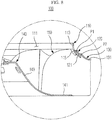
- FIG. 9 is a sectional view illustrating an air flow in the turbofan of the air conditioning system according to the illustrated embodiment of the present disclosure.
- the turbofan of the air conditioning system which is designated by reference numeral 100, includes a first shroud 110, a second shroud 120, a third shroud 130, a hub 140, and a plurality of blades 150.
- the first shroud 110 has a ring shape and is formed with an air inlet hole 111.
- the second shroud 120 is formed to be radially spaced outwards from the first shroud 110 by a predetermined clearance so that a first air passage P1 is formed between the first and second shrouds 110 and 120.
- the third shroud 130 is formed to be radially spaced outwards from the second shroud 120 by a predetermined clearance so that a second air passage P2 is formed between the second and third shrouds 120 and 130.
- the hub 140 rotates about an axis thereof through a rotational shaft (not shown) of a drive motor (not shown).
- the blades 150 are formed to be spaced apart from one another by a predetermined clearance along a circumferential direction of the hub 140 to guide air introduced through the air inlet hole 111 in the circumferential direction of the hub 140.
- the first shroud 110 has a ring shape.
- the first shroud 110 is formed, at a central area thereof, with the air inlet hole 111 having a circular shape.
- the first shroud 110 includes a first guide portion 113 and a second guide portion 115.
- the first guide portion 113 is formed in a direction perpendicular to a base 141 of the hub 140 described below to guide air introduced through the air inlet hole 111 in an axial direction of the hub 140.
- the second guide portion 115 is coupled to a portion of an upper surface of each blade 150 described below to guide air introduced through the air inlet hole 111 in the circumferential direction of the hub 140.
- Air introduced through the air inlet hole 111 is guided in the axial direction of the hub 140 by the first guide portion 113 of the first shroud 110. Subsequently, the air guided in the axial direction of the hub 140 flows in the circumferential direction of the hub 140 by rotation of the blades 150, and is then guided to a heat exchanger H by the second guide portion 115 of the first shroud 110.
- the second shroud 120 is formed to be radially spaced outwards from the first shroud 110 by a predetermined clearance.
- the second shroud 120 is formed to be spaced apart from the first shroud 110 by a predetermined clearance so that the first air passage P1 is formed at a space between the first and second shrouds 110 and 120.
- the first air passage P1 has the same ring shape as the first and second shrouds 110 and 120.
- the second shroud 120 includes a first inducing portion 121 corresponding to the second guide portion 115 of the first shroud 110 to define the first air passage P1 along with the second guide portion 115.
- the first inducing portion 121 conducts air introduced into the first air passage P1 in the circumferential direction of the hub 140.
- the first inducing portion 121 included in the second shroud 120 is coupled to a portion of the upper surface of each blade 150.
- the third shroud 130 is formed to be radially spaced outwards from the second shroud 120 by a predetermined clearance.
- the third shroud 130 is formed to be spaced apart from the second shroud 120 by a predetermined clearance so that the second air passage P2 is formed at a space between the second and third shrouds 120 and 130.
- the second air passage P2 has the same ring shape as the second and third shrouds 120 and 130.
- the third shroud 130 includes a second inducing portion 131 corresponding to the first inducing portion 121 of the second shroud 120 to define the second air passage P2 along with the first inducing portion 121.
- the second inducing portion 131 conducts air introduced into the second air passage P2 in the circumferential direction of the hub 140.
- the second inducing portion 131 included in the third shroud 130 is coupled to a portion of the upper surface of each blade 150.
- Air introduced through the air inlet hole 111 of the first shroud 110 is guided in the axial direction of the hub 140 by the first guide portion 113 of the first shroud 110. Subsequently, the air guided in the axial direction of the hub 140 flows in the circumferential direction of the hub 140 by rotation of the blades 150, and is then guided to the heat exchanger H by the second guide portion 115, the first inducing portion 121, and the second inducing portion 131 of the respective first, second, and third shrouds 110, 120, and 130.
- a portion of air to be guided to the heat exchanger H is not guided to the heat exchanger H due to various factors, for example, a difference in lengths of the heat exchanger H and each blade 150 and a position of a discharge port of the heat exchanger H, but flows toward upper portions of the first, second, and third shrouds 110, 120, and 130, thereby generating turbulent flows of air.
- a portion of turbulent air generated at upper portions of the first, second, and third shrouds 110, 120, and 130 is reintroduced into a space between the bell mouse B and the first shroud 110 by a pressure difference between air rapidly introduced through the bell mouse B and the turbulent air.
- the air reintroduced into the space between the bell mouse B and the first shroud 110 may disturb an air flow which is guided to the heat exchanger H after being introduced through the air inlet hole 111 of the first shroud 110. This causes generation of noise.
- the second shroud 120 is formed to be spaced apart from the first shroud 110 by a predetermined clearance so that the first air passage P1 is formed at the space between the first and second shrouds 110 and 120.
- the third shroud 130 is formed to be spaced apart from the second shroud 120 by a predetermined clearance so that the second air passage P2 is formed at the space between the second and third shrouds 120 and 130.
- the air reintroduced into the space between the bell mouse B and the first shroud 110 is partially introduced into the first and second air passages P1 and P2, so that the amount and velocity of air reintroduced into the space between the bell mouse B and the first shroud 110 may be reduced.
- the air introduced into the first air passage P1 is conducted toward the heat exchanger H by the first inducing portion 121 of the second shroud 120.
- the air introduced into the second air passage P2 is conducted toward the heat exchanger H by the second inducing portion 131 of the third shroud 130.
- the air flow is not disturbed while being guided to the heat exchanger H after being introduced through the air inlet hole 111 of the first shroud 110, thereby allowing the introduced air to flow smoothly toward the heat exchanger H.
- An upper end of the first inducing portion 121 has a lower height than an upper end of the second guide portion 115.
- an upper end of the second inducing portion 131 has a lower height than the upper end of the first inducing portion 121.
- the turbofan 100 of the air conditioning system may include three or more shrouds.
- a turbofan of an air conditioning system may divide a shroud into two portions to form an air passage, in order to allow, when air is reintroduced into a space between a bell mouse and the shroud, the air to be distributed throughout the air passage, thereby achieving a reduction in noise.
Landscapes
- Engineering & Computer Science (AREA)
- Mechanical Engineering (AREA)
- General Engineering & Computer Science (AREA)
- Chemical & Material Sciences (AREA)
- Combustion & Propulsion (AREA)
- Structures Of Non-Positive Displacement Pumps (AREA)
Applications Claiming Priority (1)
| Application Number | Priority Date | Filing Date | Title |
|---|---|---|---|
| KR1020110015566A KR101833935B1 (ko) | 2011-02-22 | 2011-02-22 | 공기조화기의 터보팬 |
Publications (3)
| Publication Number | Publication Date |
|---|---|
| EP2492513A2 true EP2492513A2 (de) | 2012-08-29 |
| EP2492513A3 EP2492513A3 (de) | 2017-06-21 |
| EP2492513B1 EP2492513B1 (de) | 2020-03-18 |
Family
ID=45558594
Family Applications (1)
| Application Number | Title | Priority Date | Filing Date |
|---|---|---|---|
| EP12153193.3A Active EP2492513B1 (de) | 2011-02-22 | 2012-01-31 | Ventilator eines klimaanlagensystems |
Country Status (4)
| Country | Link |
|---|---|
| US (1) | US8915698B2 (de) |
| EP (1) | EP2492513B1 (de) |
| KR (1) | KR101833935B1 (de) |
| CN (1) | CN102644625B (de) |
Cited By (2)
| Publication number | Priority date | Publication date | Assignee | Title |
|---|---|---|---|---|
| EP3273066A1 (de) * | 2016-07-22 | 2018-01-24 | ebm-papst Landshut GmbH | Gebläserad |
| US10563657B2 (en) | 2015-10-07 | 2020-02-18 | Samsung Electronics Co., Ltd. | Turbofan for air conditioning apparatus |
Families Citing this family (12)
| Publication number | Priority date | Publication date | Assignee | Title |
|---|---|---|---|---|
| US10914316B1 (en) | 2011-08-23 | 2021-02-09 | Climatecraft, Inc. | Plenum fan |
| US9568016B2 (en) * | 2013-04-23 | 2017-02-14 | Dresser-Rand Company | Impeller internal thermal cooling holes |
| KR101582603B1 (ko) * | 2014-05-09 | 2016-01-05 | 쿠쿠전자주식회사 | 자연가습 공기청정기 |
| JP6354312B2 (ja) * | 2014-05-15 | 2018-07-11 | ダイキン工業株式会社 | 空気調和装置 |
| JP6380222B2 (ja) * | 2015-04-28 | 2018-08-29 | 株式会社デンソー | 車両用空調装置 |
| JP6747402B2 (ja) * | 2017-08-11 | 2020-08-26 | 株式会社デンソー | 送風機 |
| EP3530956B1 (de) * | 2018-02-26 | 2021-09-22 | Honeywell Technologies Sarl | Laufrad für radialgebläse und gasbrennergerät |
| CN110630536A (zh) * | 2018-06-22 | 2019-12-31 | 雷勃美国公司 | 风扇和电力机械总成及其方法 |
| EP3647603A1 (de) | 2018-10-31 | 2020-05-06 | Carrier Corporation | Anordnung eines radiallaufrads eines lüfters zur geräuschverminderung |
| SE2250816A1 (en) * | 2022-06-30 | 2023-12-31 | Swegon Operations Ab | A centrifugal fan arrangement |
| GB202218545D0 (en) * | 2022-12-09 | 2023-01-25 | Cummins Generator Technologies | Fan for rotating electrical machine |
| KR102642459B1 (ko) * | 2023-09-13 | 2024-02-29 | (주)동아풍력 | 고효율 원심형 송풍기 |
Family Cites Families (19)
| Publication number | Priority date | Publication date | Assignee | Title |
|---|---|---|---|---|
| FR1528797A (fr) * | 1967-04-17 | 1968-06-14 | Lyonnaise Ventilation | Perfectionnements aux ventilateurs centrifuges |
| JPS56118593A (en) * | 1980-02-25 | 1981-09-17 | Hitachi Ltd | Blower |
| JPH09242696A (ja) * | 1996-03-11 | 1997-09-16 | Denso Corp | 遠心送風機 |
| JPH10220793A (ja) * | 1997-02-04 | 1998-08-21 | Matsushita Refrig Co Ltd | 空気調和機 |
| DE19713712C1 (de) * | 1997-04-03 | 1998-04-16 | Laengerer & Reich Gmbh & Co | Radialventilator, insbesonders als Lüfter für die Kühlanlage eines Kraftfahrzeuges |
| JP2001082384A (ja) * | 1999-09-20 | 2001-03-27 | Sanyo Electric Co Ltd | 羽根車およびこれを備えた遠心送風機 |
| CN2457374Y (zh) * | 2000-08-22 | 2001-10-31 | 大金工业株式会社 | 离心式风扇 |
| US6632071B2 (en) * | 2000-11-30 | 2003-10-14 | Lou Pauly | Blower impeller and method of lofting their blade shapes |
| CN100416108C (zh) | 2000-12-04 | 2008-09-03 | 罗伯特博施公司 | 高效单件式离心鼓风机 |
| KR100748141B1 (ko) * | 2001-08-27 | 2007-08-09 | 한라공조주식회사 | 팬과 쉬라우드의 조립체 |
| JP3698150B2 (ja) * | 2003-05-09 | 2005-09-21 | ダイキン工業株式会社 | 遠心送風機 |
| JP2005156040A (ja) | 2003-11-26 | 2005-06-16 | Mitsubishi Heavy Ind Ltd | 車両用熱交換モジュールおよびこれを備えた車両 |
| KR100611011B1 (ko) | 2005-01-07 | 2006-08-10 | 엘지전자 주식회사 | 공조기의 터보팬 |
| JP4831811B2 (ja) * | 2005-03-31 | 2011-12-07 | 三菱重工業株式会社 | 遠心式送風装置 |
| US7883312B2 (en) * | 2005-03-31 | 2011-02-08 | Mitsubishi Heavy Industries, Ltd. | Centrifugal blower |
| JP2007107435A (ja) * | 2005-10-12 | 2007-04-26 | Daikin Ind Ltd | ターボファン及びこれを用いた空気調和機 |
| JP4816045B2 (ja) | 2005-12-09 | 2011-11-16 | 株式会社富士通ゼネラル | ターボファンおよびそれを用いた空気調和機 |
| KR20080045568A (ko) * | 2006-11-20 | 2008-05-23 | 삼성전자주식회사 | 터보팬 및 이를 갖춘 공기조화기 |
| JP2010133297A (ja) * | 2008-12-03 | 2010-06-17 | Daikin Ind Ltd | 遠心送風機 |
-
2011
- 2011-02-22 KR KR1020110015566A patent/KR101833935B1/ko active IP Right Grant
-
2012
- 2012-01-31 EP EP12153193.3A patent/EP2492513B1/de active Active
- 2012-02-06 US US13/366,725 patent/US8915698B2/en active Active
- 2012-02-20 CN CN201210039006.0A patent/CN102644625B/zh active Active
Cited By (2)
| Publication number | Priority date | Publication date | Assignee | Title |
|---|---|---|---|---|
| US10563657B2 (en) | 2015-10-07 | 2020-02-18 | Samsung Electronics Co., Ltd. | Turbofan for air conditioning apparatus |
| EP3273066A1 (de) * | 2016-07-22 | 2018-01-24 | ebm-papst Landshut GmbH | Gebläserad |
Also Published As
| Publication number | Publication date |
|---|---|
| EP2492513A3 (de) | 2017-06-21 |
| EP2492513B1 (de) | 2020-03-18 |
| KR101833935B1 (ko) | 2018-03-05 |
| US20120213637A1 (en) | 2012-08-23 |
| CN102644625B (zh) | 2016-05-04 |
| KR20120096261A (ko) | 2012-08-30 |
| US8915698B2 (en) | 2014-12-23 |
| CN102644625A (zh) | 2012-08-22 |
Similar Documents
| Publication | Publication Date | Title |
|---|---|---|
| EP2492513A2 (de) | Ventilator eines Klimaanlagensystems | |
| JP5769978B2 (ja) | 遠心式ファン | |
| JP5361878B2 (ja) | ファン及びそれを備えた電子機器 | |
| JP2008101537A (ja) | 遠心式送風装置 | |
| KR20100134612A (ko) | 하이브리드 흐름 팬 장치 | |
| CN102374192B (zh) | 风扇 | |
| EP2778430B1 (de) | Externe kühleinheit einer klimatisierungsvorrichtung eines fahrzeuges | |
| JP2010132183A (ja) | 車両用熱交換モジュールおよびこれを備えた車両 | |
| EP3321512A1 (de) | Gebläse- und klimatisierungsvorrichtung | |
| US20130230421A1 (en) | Centrifugal fan | |
| US20140062232A1 (en) | Fan and electric machine assembly and methods therefor | |
| US20230332615A1 (en) | Turbofan and air-conditioning apparatus | |
| US10724377B2 (en) | Article of manufacture for turbomachine | |
| JP5041446B2 (ja) | 貫流ファン、送風機および羽根車の成形機 | |
| JP2013053533A (ja) | 軸流送風機及び空気調和機 | |
| EP3358133A1 (de) | Scheibenanordnung für gasturbinenkompressor | |
| CN216134322U (zh) | 风冷结构、盘式电机及飞行器 | |
| JP2010106854A (ja) | 貫流ファン、送風機および羽根車の成形機 | |
| JP2011137413A (ja) | 蒸気タービン | |
| US20200007008A1 (en) | Motor with Inner Fan | |
| JP4703290B2 (ja) | 送風装置 | |
| JP3128807U (ja) | 風圧を向上したファンモジュール | |
| JP6487179B2 (ja) | 送風機 | |
| EP4400777A1 (de) | In der decke eingebettete klimaanlage | |
| JP2011127452A (ja) | 車両用熱交換モジュール |
Legal Events
| Date | Code | Title | Description |
|---|---|---|---|
| PUAI | Public reference made under article 153(3) epc to a published international application that has entered the european phase |
Free format text: ORIGINAL CODE: 0009012 |
|
| AK | Designated contracting states |
Kind code of ref document: A2 Designated state(s): AL AT BE BG CH CY CZ DE DK EE ES FI FR GB GR HR HU IE IS IT LI LT LU LV MC MK MT NL NO PL PT RO RS SE SI SK SM TR |
|
| AX | Request for extension of the european patent |
Extension state: BA ME |
|
| RAP1 | Party data changed (applicant data changed or rights of an application transferred) |
Owner name: SAMSUNG ELECTRONICS CO., LTD. |
|
| PUAL | Search report despatched |
Free format text: ORIGINAL CODE: 0009013 |
|
| AK | Designated contracting states |
Kind code of ref document: A3 Designated state(s): AL AT BE BG CH CY CZ DE DK EE ES FI FR GB GR HR HU IE IS IT LI LT LU LV MC MK MT NL NO PL PT RO RS SE SI SK SM TR |
|
| AX | Request for extension of the european patent |
Extension state: BA ME |
|
| RIC1 | Information provided on ipc code assigned before grant |
Ipc: F04D 29/16 20060101AFI20170518BHEP |
|
| STAA | Information on the status of an ep patent application or granted ep patent |
Free format text: STATUS: REQUEST FOR EXAMINATION WAS MADE |
|
| 17P | Request for examination filed |
Effective date: 20170922 |
|
| RBV | Designated contracting states (corrected) |
Designated state(s): AL AT BE BG CH CY CZ DE DK EE ES FI FR GB GR HR HU IE IS IT LI LT LU LV MC MK MT NL NO PL PT RO RS SE SI SK SM TR |
|
| GRAP | Despatch of communication of intention to grant a patent |
Free format text: ORIGINAL CODE: EPIDOSNIGR1 |
|
| STAA | Information on the status of an ep patent application or granted ep patent |
Free format text: STATUS: GRANT OF PATENT IS INTENDED |
|
| INTG | Intention to grant announced |
Effective date: 20191029 |
|
| GRAS | Grant fee paid |
Free format text: ORIGINAL CODE: EPIDOSNIGR3 |
|
| GRAA | (expected) grant |
Free format text: ORIGINAL CODE: 0009210 |
|
| STAA | Information on the status of an ep patent application or granted ep patent |
Free format text: STATUS: THE PATENT HAS BEEN GRANTED |
|
| AK | Designated contracting states |
Kind code of ref document: B1 Designated state(s): AL AT BE BG CH CY CZ DE DK EE ES FI FR GB GR HR HU IE IS IT LI LT LU LV MC MK MT NL NO PL PT RO RS SE SI SK SM TR |
|
| REG | Reference to a national code |
Ref country code: GB Ref legal event code: FG4D |
|
| REG | Reference to a national code |
Ref country code: DE Ref legal event code: R096 Ref document number: 602012068512 Country of ref document: DE |
|
| REG | Reference to a national code |
Ref country code: AT Ref legal event code: REF Ref document number: 1246205 Country of ref document: AT Kind code of ref document: T Effective date: 20200415 Ref country code: IE Ref legal event code: FG4D |
|
| PG25 | Lapsed in a contracting state [announced via postgrant information from national office to epo] |
Ref country code: FI Free format text: LAPSE BECAUSE OF FAILURE TO SUBMIT A TRANSLATION OF THE DESCRIPTION OR TO PAY THE FEE WITHIN THE PRESCRIBED TIME-LIMIT Effective date: 20200318 Ref country code: NO Free format text: LAPSE BECAUSE OF FAILURE TO SUBMIT A TRANSLATION OF THE DESCRIPTION OR TO PAY THE FEE WITHIN THE PRESCRIBED TIME-LIMIT Effective date: 20200618 Ref country code: RS Free format text: LAPSE BECAUSE OF FAILURE TO SUBMIT A TRANSLATION OF THE DESCRIPTION OR TO PAY THE FEE WITHIN THE PRESCRIBED TIME-LIMIT Effective date: 20200318 |
|
| REG | Reference to a national code |
Ref country code: NL Ref legal event code: MP Effective date: 20200318 |
|
| PG25 | Lapsed in a contracting state [announced via postgrant information from national office to epo] |
Ref country code: BG Free format text: LAPSE BECAUSE OF FAILURE TO SUBMIT A TRANSLATION OF THE DESCRIPTION OR TO PAY THE FEE WITHIN THE PRESCRIBED TIME-LIMIT Effective date: 20200618 Ref country code: HR Free format text: LAPSE BECAUSE OF FAILURE TO SUBMIT A TRANSLATION OF THE DESCRIPTION OR TO PAY THE FEE WITHIN THE PRESCRIBED TIME-LIMIT Effective date: 20200318 Ref country code: SE Free format text: LAPSE BECAUSE OF FAILURE TO SUBMIT A TRANSLATION OF THE DESCRIPTION OR TO PAY THE FEE WITHIN THE PRESCRIBED TIME-LIMIT Effective date: 20200318 Ref country code: GR Free format text: LAPSE BECAUSE OF FAILURE TO SUBMIT A TRANSLATION OF THE DESCRIPTION OR TO PAY THE FEE WITHIN THE PRESCRIBED TIME-LIMIT Effective date: 20200619 Ref country code: LV Free format text: LAPSE BECAUSE OF FAILURE TO SUBMIT A TRANSLATION OF THE DESCRIPTION OR TO PAY THE FEE WITHIN THE PRESCRIBED TIME-LIMIT Effective date: 20200318 |
|
| REG | Reference to a national code |
Ref country code: LT Ref legal event code: MG4D |
|
| PG25 | Lapsed in a contracting state [announced via postgrant information from national office to epo] |
Ref country code: NL Free format text: LAPSE BECAUSE OF FAILURE TO SUBMIT A TRANSLATION OF THE DESCRIPTION OR TO PAY THE FEE WITHIN THE PRESCRIBED TIME-LIMIT Effective date: 20200318 |
|
| PG25 | Lapsed in a contracting state [announced via postgrant information from national office to epo] |
Ref country code: SM Free format text: LAPSE BECAUSE OF FAILURE TO SUBMIT A TRANSLATION OF THE DESCRIPTION OR TO PAY THE FEE WITHIN THE PRESCRIBED TIME-LIMIT Effective date: 20200318 Ref country code: RO Free format text: LAPSE BECAUSE OF FAILURE TO SUBMIT A TRANSLATION OF THE DESCRIPTION OR TO PAY THE FEE WITHIN THE PRESCRIBED TIME-LIMIT Effective date: 20200318 Ref country code: CZ Free format text: LAPSE BECAUSE OF FAILURE TO SUBMIT A TRANSLATION OF THE DESCRIPTION OR TO PAY THE FEE WITHIN THE PRESCRIBED TIME-LIMIT Effective date: 20200318 Ref country code: IS Free format text: LAPSE BECAUSE OF FAILURE TO SUBMIT A TRANSLATION OF THE DESCRIPTION OR TO PAY THE FEE WITHIN THE PRESCRIBED TIME-LIMIT Effective date: 20200718 Ref country code: SK Free format text: LAPSE BECAUSE OF FAILURE TO SUBMIT A TRANSLATION OF THE DESCRIPTION OR TO PAY THE FEE WITHIN THE PRESCRIBED TIME-LIMIT Effective date: 20200318 Ref country code: PT Free format text: LAPSE BECAUSE OF FAILURE TO SUBMIT A TRANSLATION OF THE DESCRIPTION OR TO PAY THE FEE WITHIN THE PRESCRIBED TIME-LIMIT Effective date: 20200812 Ref country code: EE Free format text: LAPSE BECAUSE OF FAILURE TO SUBMIT A TRANSLATION OF THE DESCRIPTION OR TO PAY THE FEE WITHIN THE PRESCRIBED TIME-LIMIT Effective date: 20200318 Ref country code: LT Free format text: LAPSE BECAUSE OF FAILURE TO SUBMIT A TRANSLATION OF THE DESCRIPTION OR TO PAY THE FEE WITHIN THE PRESCRIBED TIME-LIMIT Effective date: 20200318 |
|
| REG | Reference to a national code |
Ref country code: AT Ref legal event code: MK05 Ref document number: 1246205 Country of ref document: AT Kind code of ref document: T Effective date: 20200318 |
|
| REG | Reference to a national code |
Ref country code: DE Ref legal event code: R097 Ref document number: 602012068512 Country of ref document: DE |
|
| PLBE | No opposition filed within time limit |
Free format text: ORIGINAL CODE: 0009261 |
|
| STAA | Information on the status of an ep patent application or granted ep patent |
Free format text: STATUS: NO OPPOSITION FILED WITHIN TIME LIMIT |
|
| PG25 | Lapsed in a contracting state [announced via postgrant information from national office to epo] |
Ref country code: IT Free format text: LAPSE BECAUSE OF FAILURE TO SUBMIT A TRANSLATION OF THE DESCRIPTION OR TO PAY THE FEE WITHIN THE PRESCRIBED TIME-LIMIT Effective date: 20200318 Ref country code: AT Free format text: LAPSE BECAUSE OF FAILURE TO SUBMIT A TRANSLATION OF THE DESCRIPTION OR TO PAY THE FEE WITHIN THE PRESCRIBED TIME-LIMIT Effective date: 20200318 Ref country code: DK Free format text: LAPSE BECAUSE OF FAILURE TO SUBMIT A TRANSLATION OF THE DESCRIPTION OR TO PAY THE FEE WITHIN THE PRESCRIBED TIME-LIMIT Effective date: 20200318 Ref country code: ES Free format text: LAPSE BECAUSE OF FAILURE TO SUBMIT A TRANSLATION OF THE DESCRIPTION OR TO PAY THE FEE WITHIN THE PRESCRIBED TIME-LIMIT Effective date: 20200318 |
|
| 26N | No opposition filed |
Effective date: 20201221 |
|
| PG25 | Lapsed in a contracting state [announced via postgrant information from national office to epo] |
Ref country code: PL Free format text: LAPSE BECAUSE OF FAILURE TO SUBMIT A TRANSLATION OF THE DESCRIPTION OR TO PAY THE FEE WITHIN THE PRESCRIBED TIME-LIMIT Effective date: 20200318 |
|
| PG25 | Lapsed in a contracting state [announced via postgrant information from national office to epo] |
Ref country code: SI Free format text: LAPSE BECAUSE OF FAILURE TO SUBMIT A TRANSLATION OF THE DESCRIPTION OR TO PAY THE FEE WITHIN THE PRESCRIBED TIME-LIMIT Effective date: 20200318 |
|
| PG25 | Lapsed in a contracting state [announced via postgrant information from national office to epo] |
Ref country code: MC Free format text: LAPSE BECAUSE OF FAILURE TO SUBMIT A TRANSLATION OF THE DESCRIPTION OR TO PAY THE FEE WITHIN THE PRESCRIBED TIME-LIMIT Effective date: 20200318 |
|
| REG | Reference to a national code |
Ref country code: CH Ref legal event code: PL |
|
| PG25 | Lapsed in a contracting state [announced via postgrant information from national office to epo] |
Ref country code: LU Free format text: LAPSE BECAUSE OF NON-PAYMENT OF DUE FEES Effective date: 20210131 |
|
| REG | Reference to a national code |
Ref country code: BE Ref legal event code: MM Effective date: 20210131 |
|
| PG25 | Lapsed in a contracting state [announced via postgrant information from national office to epo] |
Ref country code: FR Free format text: LAPSE BECAUSE OF NON-PAYMENT OF DUE FEES Effective date: 20210131 |
|
| PG25 | Lapsed in a contracting state [announced via postgrant information from national office to epo] |
Ref country code: CH Free format text: LAPSE BECAUSE OF NON-PAYMENT OF DUE FEES Effective date: 20210131 Ref country code: LI Free format text: LAPSE BECAUSE OF NON-PAYMENT OF DUE FEES Effective date: 20210131 |
|
| PG25 | Lapsed in a contracting state [announced via postgrant information from national office to epo] |
Ref country code: IE Free format text: LAPSE BECAUSE OF NON-PAYMENT OF DUE FEES Effective date: 20210131 |
|
| PG25 | Lapsed in a contracting state [announced via postgrant information from national office to epo] |
Ref country code: BE Free format text: LAPSE BECAUSE OF NON-PAYMENT OF DUE FEES Effective date: 20210131 |
|
| PGFP | Annual fee paid to national office [announced via postgrant information from national office to epo] |
Ref country code: GB Payment date: 20221220 Year of fee payment: 12 |
|
| PG25 | Lapsed in a contracting state [announced via postgrant information from national office to epo] |
Ref country code: HU Free format text: LAPSE BECAUSE OF FAILURE TO SUBMIT A TRANSLATION OF THE DESCRIPTION OR TO PAY THE FEE WITHIN THE PRESCRIBED TIME-LIMIT; INVALID AB INITIO Effective date: 20120131 Ref country code: CY Free format text: LAPSE BECAUSE OF FAILURE TO SUBMIT A TRANSLATION OF THE DESCRIPTION OR TO PAY THE FEE WITHIN THE PRESCRIBED TIME-LIMIT Effective date: 20200318 |
|
| PG25 | Lapsed in a contracting state [announced via postgrant information from national office to epo] |
Ref country code: MK Free format text: LAPSE BECAUSE OF FAILURE TO SUBMIT A TRANSLATION OF THE DESCRIPTION OR TO PAY THE FEE WITHIN THE PRESCRIBED TIME-LIMIT Effective date: 20200318 |
|
| PGFP | Annual fee paid to national office [announced via postgrant information from national office to epo] |
Ref country code: DE Payment date: 20231220 Year of fee payment: 13 |
|
| PG25 | Lapsed in a contracting state [announced via postgrant information from national office to epo] |
Ref country code: TR Free format text: LAPSE BECAUSE OF FAILURE TO SUBMIT A TRANSLATION OF THE DESCRIPTION OR TO PAY THE FEE WITHIN THE PRESCRIBED TIME-LIMIT Effective date: 20200318 |