EP2492361A2 - High strength steel pipe with excellent toughness at low temperature and good sulfide stress corrosion cracking resistance - Google Patents
High strength steel pipe with excellent toughness at low temperature and good sulfide stress corrosion cracking resistance Download PDFInfo
- Publication number
- EP2492361A2 EP2492361A2 EP12154023A EP12154023A EP2492361A2 EP 2492361 A2 EP2492361 A2 EP 2492361A2 EP 12154023 A EP12154023 A EP 12154023A EP 12154023 A EP12154023 A EP 12154023A EP 2492361 A2 EP2492361 A2 EP 2492361A2
- Authority
- EP
- European Patent Office
- Prior art keywords
- equal
- steel
- steel pipe
- less
- ksi
- Prior art date
- Legal status (The legal status is an assumption and is not a legal conclusion. Google has not performed a legal analysis and makes no representation as to the accuracy of the status listed.)
- Granted
Links
Images


Classifications
-
- C—CHEMISTRY; METALLURGY
- C21—METALLURGY OF IRON
- C21D—MODIFYING THE PHYSICAL STRUCTURE OF FERROUS METALS; GENERAL DEVICES FOR HEAT TREATMENT OF FERROUS OR NON-FERROUS METALS OR ALLOYS; MAKING METAL MALLEABLE, e.g. BY DECARBURISATION OR TEMPERING
- C21D8/00—Modifying the physical properties by deformation combined with, or followed by, heat treatment
- C21D8/10—Modifying the physical properties by deformation combined with, or followed by, heat treatment during manufacturing of tubular bodies
-
- C—CHEMISTRY; METALLURGY
- C21—METALLURGY OF IRON
- C21D—MODIFYING THE PHYSICAL STRUCTURE OF FERROUS METALS; GENERAL DEVICES FOR HEAT TREATMENT OF FERROUS OR NON-FERROUS METALS OR ALLOYS; MAKING METAL MALLEABLE, e.g. BY DECARBURISATION OR TEMPERING
- C21D1/00—General methods or devices for heat treatment, e.g. annealing, hardening, quenching or tempering
- C21D1/18—Hardening; Quenching with or without subsequent tempering
-
- C—CHEMISTRY; METALLURGY
- C21—METALLURGY OF IRON
- C21D—MODIFYING THE PHYSICAL STRUCTURE OF FERROUS METALS; GENERAL DEVICES FOR HEAT TREATMENT OF FERROUS OR NON-FERROUS METALS OR ALLOYS; MAKING METAL MALLEABLE, e.g. BY DECARBURISATION OR TEMPERING
- C21D6/00—Heat treatment of ferrous alloys
- C21D6/002—Heat treatment of ferrous alloys containing Cr
-
- C—CHEMISTRY; METALLURGY
- C21—METALLURGY OF IRON
- C21D—MODIFYING THE PHYSICAL STRUCTURE OF FERROUS METALS; GENERAL DEVICES FOR HEAT TREATMENT OF FERROUS OR NON-FERROUS METALS OR ALLOYS; MAKING METAL MALLEABLE, e.g. BY DECARBURISATION OR TEMPERING
- C21D9/00—Heat treatment, e.g. annealing, hardening, quenching or tempering, adapted for particular articles; Furnaces therefor
- C21D9/08—Heat treatment, e.g. annealing, hardening, quenching or tempering, adapted for particular articles; Furnaces therefor for tubular bodies or pipes
- C21D9/085—Cooling or quenching
-
- C—CHEMISTRY; METALLURGY
- C22—METALLURGY; FERROUS OR NON-FERROUS ALLOYS; TREATMENT OF ALLOYS OR NON-FERROUS METALS
- C22C—ALLOYS
- C22C38/00—Ferrous alloys, e.g. steel alloys
- C22C38/001—Ferrous alloys, e.g. steel alloys containing N
-
- C—CHEMISTRY; METALLURGY
- C22—METALLURGY; FERROUS OR NON-FERROUS ALLOYS; TREATMENT OF ALLOYS OR NON-FERROUS METALS
- C22C—ALLOYS
- C22C38/00—Ferrous alloys, e.g. steel alloys
- C22C38/002—Ferrous alloys, e.g. steel alloys containing In, Mg, or other elements not provided for in one single group C22C38/001 - C22C38/60
-
- C—CHEMISTRY; METALLURGY
- C22—METALLURGY; FERROUS OR NON-FERROUS ALLOYS; TREATMENT OF ALLOYS OR NON-FERROUS METALS
- C22C—ALLOYS
- C22C38/00—Ferrous alloys, e.g. steel alloys
- C22C38/008—Ferrous alloys, e.g. steel alloys containing tin
-
- C—CHEMISTRY; METALLURGY
- C22—METALLURGY; FERROUS OR NON-FERROUS ALLOYS; TREATMENT OF ALLOYS OR NON-FERROUS METALS
- C22C—ALLOYS
- C22C38/00—Ferrous alloys, e.g. steel alloys
- C22C38/02—Ferrous alloys, e.g. steel alloys containing silicon
-
- C—CHEMISTRY; METALLURGY
- C22—METALLURGY; FERROUS OR NON-FERROUS ALLOYS; TREATMENT OF ALLOYS OR NON-FERROUS METALS
- C22C—ALLOYS
- C22C38/00—Ferrous alloys, e.g. steel alloys
- C22C38/04—Ferrous alloys, e.g. steel alloys containing manganese
-
- C—CHEMISTRY; METALLURGY
- C22—METALLURGY; FERROUS OR NON-FERROUS ALLOYS; TREATMENT OF ALLOYS OR NON-FERROUS METALS
- C22C—ALLOYS
- C22C38/00—Ferrous alloys, e.g. steel alloys
- C22C38/06—Ferrous alloys, e.g. steel alloys containing aluminium
-
- C—CHEMISTRY; METALLURGY
- C22—METALLURGY; FERROUS OR NON-FERROUS ALLOYS; TREATMENT OF ALLOYS OR NON-FERROUS METALS
- C22C—ALLOYS
- C22C38/00—Ferrous alloys, e.g. steel alloys
- C22C38/08—Ferrous alloys, e.g. steel alloys containing nickel
-
- C—CHEMISTRY; METALLURGY
- C22—METALLURGY; FERROUS OR NON-FERROUS ALLOYS; TREATMENT OF ALLOYS OR NON-FERROUS METALS
- C22C—ALLOYS
- C22C38/00—Ferrous alloys, e.g. steel alloys
- C22C38/18—Ferrous alloys, e.g. steel alloys containing chromium
- C22C38/22—Ferrous alloys, e.g. steel alloys containing chromium with molybdenum or tungsten
-
- C—CHEMISTRY; METALLURGY
- C22—METALLURGY; FERROUS OR NON-FERROUS ALLOYS; TREATMENT OF ALLOYS OR NON-FERROUS METALS
- C22C—ALLOYS
- C22C38/00—Ferrous alloys, e.g. steel alloys
- C22C38/18—Ferrous alloys, e.g. steel alloys containing chromium
- C22C38/24—Ferrous alloys, e.g. steel alloys containing chromium with vanadium
-
- C—CHEMISTRY; METALLURGY
- C22—METALLURGY; FERROUS OR NON-FERROUS ALLOYS; TREATMENT OF ALLOYS OR NON-FERROUS METALS
- C22C—ALLOYS
- C22C38/00—Ferrous alloys, e.g. steel alloys
- C22C38/18—Ferrous alloys, e.g. steel alloys containing chromium
- C22C38/40—Ferrous alloys, e.g. steel alloys containing chromium with nickel
- C22C38/42—Ferrous alloys, e.g. steel alloys containing chromium with nickel with copper
-
- C—CHEMISTRY; METALLURGY
- C22—METALLURGY; FERROUS OR NON-FERROUS ALLOYS; TREATMENT OF ALLOYS OR NON-FERROUS METALS
- C22C—ALLOYS
- C22C38/00—Ferrous alloys, e.g. steel alloys
- C22C38/18—Ferrous alloys, e.g. steel alloys containing chromium
- C22C38/40—Ferrous alloys, e.g. steel alloys containing chromium with nickel
- C22C38/44—Ferrous alloys, e.g. steel alloys containing chromium with nickel with molybdenum or tungsten
-
- C—CHEMISTRY; METALLURGY
- C22—METALLURGY; FERROUS OR NON-FERROUS ALLOYS; TREATMENT OF ALLOYS OR NON-FERROUS METALS
- C22C—ALLOYS
- C22C38/00—Ferrous alloys, e.g. steel alloys
- C22C38/18—Ferrous alloys, e.g. steel alloys containing chromium
- C22C38/40—Ferrous alloys, e.g. steel alloys containing chromium with nickel
- C22C38/46—Ferrous alloys, e.g. steel alloys containing chromium with nickel with vanadium
-
- C—CHEMISTRY; METALLURGY
- C22—METALLURGY; FERROUS OR NON-FERROUS ALLOYS; TREATMENT OF ALLOYS OR NON-FERROUS METALS
- C22C—ALLOYS
- C22C38/00—Ferrous alloys, e.g. steel alloys
- C22C38/18—Ferrous alloys, e.g. steel alloys containing chromium
- C22C38/40—Ferrous alloys, e.g. steel alloys containing chromium with nickel
- C22C38/50—Ferrous alloys, e.g. steel alloys containing chromium with nickel with titanium or zirconium
-
- C—CHEMISTRY; METALLURGY
- C22—METALLURGY; FERROUS OR NON-FERROUS ALLOYS; TREATMENT OF ALLOYS OR NON-FERROUS METALS
- C22C—ALLOYS
- C22C38/00—Ferrous alloys, e.g. steel alloys
- C22C38/60—Ferrous alloys, e.g. steel alloys containing lead, selenium, tellurium, or antimony, or more than 0.04% by weight of sulfur
-
- C—CHEMISTRY; METALLURGY
- C21—METALLURGY OF IRON
- C21D—MODIFYING THE PHYSICAL STRUCTURE OF FERROUS METALS; GENERAL DEVICES FOR HEAT TREATMENT OF FERROUS OR NON-FERROUS METALS OR ALLOYS; MAKING METAL MALLEABLE, e.g. BY DECARBURISATION OR TEMPERING
- C21D2211/00—Microstructure comprising significant phases
- C21D2211/002—Bainite
-
- C—CHEMISTRY; METALLURGY
- C21—METALLURGY OF IRON
- C21D—MODIFYING THE PHYSICAL STRUCTURE OF FERROUS METALS; GENERAL DEVICES FOR HEAT TREATMENT OF FERROUS OR NON-FERROUS METALS OR ALLOYS; MAKING METAL MALLEABLE, e.g. BY DECARBURISATION OR TEMPERING
- C21D2211/00—Microstructure comprising significant phases
- C21D2211/008—Martensite
-
- C—CHEMISTRY; METALLURGY
- C21—METALLURGY OF IRON
- C21D—MODIFYING THE PHYSICAL STRUCTURE OF FERROUS METALS; GENERAL DEVICES FOR HEAT TREATMENT OF FERROUS OR NON-FERROUS METALS OR ALLOYS; MAKING METAL MALLEABLE, e.g. BY DECARBURISATION OR TEMPERING
- C21D8/00—Modifying the physical properties by deformation combined with, or followed by, heat treatment
- C21D8/10—Modifying the physical properties by deformation combined with, or followed by, heat treatment during manufacturing of tubular bodies
- C21D8/105—Modifying the physical properties by deformation combined with, or followed by, heat treatment during manufacturing of tubular bodies of ferrous alloys
Definitions
- the present invention relates generally to metal production and, in certain embodiments, relates to methods of producing metallic tubular bars having high toughness at low temperature while concurrently possessing sulfide stress corrosion cracking resistance. Certain embodiments relate to seamless steel pipes for risers of all kinds (catenary, hybrid, top tension, work over, drilling, etc), line pipes and flow lines for use in the oil and gas industry, including pipes that are suitable for bending.
- a core component in deep and ultra-deep sea production is the circulation of fluids from the seafloor to the surface system.
- Risers the pipes which connect the drilling or production platform to the well, are exposed over considerable length (now exceeding roughly 10,000 feet, or approximately 2 miles) to the straining pressures of multiple ocean currents.
- Embodiments of the invention are directed to steel pipes or tubes and methods of manufacturing the same.
- seamless quenched and tempered steel pipes for riser and line pipes are provided having wall thickness (WT) between 8 to 35 mm with a minimum yield strength of 70 ksi, 80 ksi, and 90 ksi, respectively, with excellent low temperature toughness and corrosion resistance (sour service, H 2 S environment).
- the seamless pipes are also suitable to produce bends of the same grade by hot induction bending and off-line quenching and tempering treatment.
- the steel pipe has an outside diameter (OD) between 6" (152 mm) and 28" (711 mm), and wall thickness (WT) from 8 to 35 mm.
- the composition of a seamless, low-alloy steel pipe consists of (by weight): 0.05%-0.16% C, 0.20%-0.90% Mn, 0.10%-0.50% Si, 1.20%-2.60% Cr, 0.05%-0.50% Ni, 0.80%-1.20% Mo, 0.03% Nb max, 0.02% Ti max, 0.005%-0.12% V, 0.008%-0.040% Al, 0.0030-0.012% N, 0.3% Cu max, 0.01% S max, 0.02% P max, 0.001-0.005% Ca, 0.0020% B max, 0.020% As max, 0.0050% Sb max, 0.020% Sn max, 0.030% Zr max, 0.030% Ta max, 0.0050% Bi max, 0.0030% O max, 0.00030% H max, with the balance being iron and inevitable impurities.
- the steel pipes may be manufactured into different grades.
- a 70 ksi grade is provided with the following properties:
- an 80 ksi grade is provided with the following properties:
- a 90 ksi grade is provided with the following properties:
- the steel pipe may have a minimum impact energy of 250 J / 200 J (average / individual) and minimum 80% of average shear area for both longitudinal and transverse Charpy V-notch (CVN) tests performed at about -70°C according with standard ISO 148-1.
- the 80 ksi grade pipe may have a hardness of 248 HV10 maximum.
- the 90 ksi grade pipe may have a hardness of 270 HV 10 maximum.
- Steel pipes manufactured according to embodiments of the invention may exhibit resistance to both hydrogen induced cracking (HIC) and sulfide stress corrosion (SSC) cracking.
- HIC test performed according with NACE Standard TM0284-2003 Item No. 21215, using NACE solution A and test duration 96 hours, provides the following HIC parameters (average on three sections of three specimens):
- SSC testing performed in accordance with NACE TM0177, using test solution A, test duration 720 hours provides no failure at 90% of SMYS for grades 70 ksi and 80 ksi and no failure at 72% SMYS for 90 ksi grade.
- Steel pipes manufactured according to certain embodiments of the invention have a microstructure exhibiting no ferrite, no upper bainite, and no granular bainite. They may be constituted of tempered martensite with a volume percentage greater than 60%, preferably greater than 90%, most preferably greater than 95% (measured according with ASTM E562-08) and tempered lower bainite with volume percentage less than 40%, preferably less than 10%, most preferably less than 5%. Martensite and bainite may be formed at temperatures lower than 450 °C and 540 °C respectively, after re-heating at temperatures of 900°C to 1060°C for soaking times from 300 s to 3600 s, and quenching at cooling rates greater than 20°C/s.
- the average prior austenite grain size measured by ASTM E112 standard is greater than 15 ⁇ m or 20 ⁇ m (lineal intercept) and smaller than 100 ⁇ m.
- the packet size of the steel pipes after tempering may possess a packet size (i.e., the average size of regions separated by high angle boundaries smaller than 6 ⁇ m. In further embodiments, the packet size may be smaller than about 4 ⁇ m. In other embodiments, the packet size may be smaller than about 3 ⁇ m. Packet size may be measured as the average lineal intercept on images taken by Scanning Electron Microscopy (SEM) using the Electron Back Scattered Diffraction (EBSD) signal, with high-angle boundaries considered to be those boundaries with a misorientation > 45°.
- SEM Scanning Electron Microscopy
- EBSD Electron Back Scattered Diffraction
- the steel pipes after tempering may exhibit the presence of fine and coarse precipitates.
- the fine precipitates may be of the type MX, M 2 X, where M is V, Mo, Nb, or Cr and X is C or N.
- the average diameter of the fine precipitates may be less than about 40 nm.
- the coarse precipitates may be of the type M 3 C, M 6 C, M 23 C 6 .
- the average diameter of the coarse precipitates may be within the range between about 80 nm to about 400 nm.
- the precipitates may be examined by Transmission Electron Microscopy (TEM) using the extraction replica method.
- TEM Transmission Electron Microscopy
- a steel pipe comprises a steel composition comprising:
- the wall thickness of the steel pipe may be greater than or equal to about 8 mm and less than about 35 mm.
- the steel pipe may be processed to have a yield strength greater than about 70 ksi and the microstructure of the steel tube may comprise martensite in a volume percentage greater than or equal to about 60 % and lower bainite in a volume percentage less than or equal to about 40 %
- a method of making a steel pipe comprises providing a steel having a steel composition (e.g., a low-alloy steel). The method further comprises forming the steel into a tube having a wall thickness greater than or equal to about 8 mm and less than about 35 mm. The method additionally comprises heating the formed steel tube in a first heating operation to a temperature within the range between about 900°C to about 1060°C.
- a steel composition e.g., a low-alloy steel
- the method also comprises quenching the formed steel tube at a cooling rate greater than or equal to about 20°C/sec, wherein the microstructure of the quenched steel is greater than or equal to about 60% martensite and less than or equal to about 40% lower bainite and has an average prior austenite grain size measured by ASTM E112 greater than about 15 ⁇ m.
- the method additionally comprises tempering the quenched steel tube at a temperature within the range between about 680°C to about 760°C, wherein the steel tube after tempering has a yield strength greater than about 70 ksi and an average Charpy V-notch energy greater or equal to about 150 J/cm 2 at about -70°C. In other embodiments, the average Charpy V-notch energy of the steel tube is greater or equal to about 250 J/cm 2 at about -70°C.
- an 80 ksi grade seamless steel pipe is provided.
- the pipe comprises:
- the wall thickness of the steel pipe may be greater than or equal to about 8 mm and less than or equal to about 35 mm.
- the steel pipe may be processed by hot rolling followed by cooling to room temperature, heating to a temperature of about 900°C or above, quenching at a cooling rate greater than or equal to 40°C/sec, and tempering at a temperature between about 680°C to about 760°C, to form a microstructure having a prior austenite grain size of about 20 ⁇ m to about 80 ⁇ m, a packet size of about 3 ⁇ m to about 6 ⁇ m, and about 90% martensite by volume or greater, and about 10% lower bainite by volume or less.
- the steel pipe may have a yield strength (YS) between about 80 ksi and about 102 ksi, an ultimate tensile strength (UTS) between about 90 ksi and about 120 ksi, elongation no less than about 20%, and YS/UTS ratio no higher than about 0.93.
- YS yield strength
- UTS ultimate tensile strength
- a 90 ksi grade seamless steel pipe may be provided.
- the pipe comprises:
- the wall thickness of the steel pipe may be greater than or equal to about 8 mm and less than or equal to about 35 mm.
- the steel pipe may be processed by hot rolling followed by cooling to room temperature, heating to a temperature of about 900°C or above, quenching at a cooling rate greater than or equal to about 20°C/sec, and tempering at a temperature between about 680°C to about 760°C, to form a microstructure having a prior austenite grain size of about 20 ⁇ m to about 60 ⁇ m, a packet size of about 2 ⁇ m to about 6 ⁇ m, and about 95% martensite by volume or greater, and about 5% lower bainite by volume or less.
- the steel pipe may have a yield strength (YS) between about 90 ksi and about 112 ksi, an ultimate tensile strength (UTS) between 100 ksi and 133 ksi, elongation no less than about 18%, and YS/UTS ratio no higher than about 0.95.
- YS yield strength
- UTS ultimate tensile strength
- a 70 ksi grade seamless steel pipe may be provided.
- the pipe comprises:
- the wall thickness of the steel pipe may be greater than or equal to about 8 mm and less than or equal to about 35 mm.
- the steel pipe may be processed by hot rolling followed by cooling to room temperature, heating to a temperature of about 900°C or above, quenching at a cooling rate greater than or equal to about 20°C/sec, and tempering at a temperature between about 680°C to about 760°C, to form a microstructure having a prior austenite grain size of about 20 ⁇ m to about 100 ⁇ m, a packet size of about 4 ⁇ m to about 6 ⁇ m, and about 60% martensite by volume or greater, and about 40% lower bainite by volume or less.
- the steel pipe may have a yield strength (YS) between about 70 ksi and about 92 ksi, an ultimate tensile strength (UTS) between about 83 ksi and about 110 ksi, elongation no less than about 18%, and YS/UTS ratio no higher than about 0.93.
- YS yield strength
- UTS ultimate tensile strength
- Embodiments of the present disclosure provide steel compositions, tubular bars (e.g., pipes) formed using the steel compositions, and respective methods of manufacture.
- the tubular bars may be employed, for example, as line pipes and risers for use in the oil and gas industry.
- the tubular bars may possess wall thicknesses greater than or equal to about 8 mm and less than about 35 mm and a microstructure of martensite and lower bainite without substantial ferrite, upper bainite, or granular bainite. So formed, the tubular bars may possess a minimum yield strength of about 70 ksi, 80 ksi, and about 90 ksi.
- tubular bars may possess good toughness at low temperatures and resistance to sulfide stress corrosion cracking (SSC) and hydrogen induced cracking (HIC), enabling use of the tubular bars in sour service environments.
- SSC sulfide stress corrosion cracking
- HIC hydrogen induced cracking
- bar as used herein is a broad term and includes its ordinary dictionary meaning and also refers to a generally hollow, elongate member which may be straight or have bends or curves and be formed to a predetermined shape, and any additional forming required to secure the formed tubular bar in its intended location.
- the bar may be tubular, having a substantially circular outer surface and inner surface, although other shapes and cross-sections are contemplated as well.
- tubular refers to any elongate, hollow shape, which need not be circular or cylindrical.
- the terms “approximately,” “about,” and “substantially,” as used herein represent an amount close to the stated amount that still performs a desired function or achieves a desired result.
- the terms “approximately,” “about,” and “substantially” may refer to an amount that is within less than 10% of, within less than 5% of, within less than 1% of, within less than 0.1% of, and within less than 0.01% of the stated amount.
- room temperature has its ordinary meaning as known to those skilled in the art and may include temperatures within the range of about 16°C (60°F) to about 32°C (90°F).
- Embodiments of the present disclosure comprise low-alloy carbon steel pipes and methods of manufacture. As discussed in greater detail below, through a combination of steel composition and heat treatment, a final microstructure may be achieved that gives rise to selected mechanical properties of interest, including one or more of minimum yield strength, toughness, hardness and corrosion resistance, in high wall thickness pipes (e.g., WT greater than or equal to about 8 mm and less than about 35 mm).
- the steel composition of the present disclosure may comprise not only carbon (C) but also manganese (Mn), silicon (Si), chromium (Cr), nickel (Ni), molybdenum (Mo), vanadium (V), aluminum (Al), nitrogen (N), and calcium (Ca). Additionally, one or more of the following elements may be optionally present and/or added as well: tungsten (W), niobium (Nb), titanium (Ti), boron (B), zirconium (Zr), and tantalum (Ta). The remainder of the composition may comprise iron (Fe) and impurities. In certain embodiments, the concentration of impurities may be reduced to as low an amount as possible.
- Embodiments of impurities may include, but are not limited to, copper (Cu), sulfur (S), phosphorous (P), arsenic (As), antimony (Sb), tin (Sn), bismuth (Bi), oxygen (O), and hydrogen (H).
- the low-alloy steel composition may comprise (in weight % unless otherwise noted):
- the heat treatment operations may include quenching and tempering (Q+T).
- the quenching operation may include reheating a pipe from about room temperature after hot forming to a temperature that austenitizes the pipe followed by a rapid quench.
- the pipe may be heated to a temperature within the range between about 900°C to about 1060°C and held at about the austenitizing temperature for a selected soaking time.
- Cooling rates during the quench are selected so as to achieve a selected cooling rate at about the mid-wall of the pipe.
- pipes may be cooled so as to achieve cooling rates greater than or equal to about 20°C/s at the mid-wall.
- the cooling rate may be greater than or equal to about 40°C/sec, as discussed in greater detail below.
- Quenching pipes having a WT greater than or equal to about 8 mm and less than about 35 mm and the composition described above may promote the formation of a volume percent of martensite greater than about 60%, preferably greater than about 90% and more preferably greater than about 95% within the pipe.
- the remaining microstructure of the pipe may comprise lower bainite, with substantially no ferrite, upper bainite, or granular bainite.
- the microstructure of the pipe may comprise substantially 100% martensite.
- the pipe may be further subjected to tempering. Tempering may be conducted at a temperature within the range between about 680°C to about 760°C, depending upon the composition of the steel and the target yield strength.
- the microstructure may further exhibit an average prior austenite grain size measured according to ASTM E112 of between about 15 ⁇ m to about 100 ⁇ m.
- the microstructure may also exhibit an average packet size of less than or equal to about 6 ⁇ m, preferably less than or equal to about 4 ⁇ m, most preferably less than or equal to about 3 ⁇ m.
- formed pipe may further exhibit the following resistance to sulfide stress corrosion (SSC) cracking and hydrogen induced cracking (HIC).
- SSC testing is conducted according to NACE TM 0177 using solution A with a test duration of about 720 hours.
- the method 100 includes steel making operations 102, hot forming operations 104, heat treatment operations 106, which may include austenitizing 106A, quenching 106B, tempering 106C, and finishing operations 110. It may be understood that the method 100 may include greater or fewer operations and the operations may be performed in a different order than that illustrated in Figure 1 , as necessary.
- Operation 102 of the method 100 preferably comprises fabrication of the steel and production of a solid metal billet capable of being pierced and rolled to form a metallic tubular bar.
- selected steel scrap, cast iron, and sponge iron may be employed to prepare the raw material for the steel composition. It may be understood, however, that other sources of iron and/or steel may be employed for preparation of the steel composition.
- Primary steelmaking may be performed using an electric arc furnace to melt the steel, decrease phosphorous and other impurities, and achieve a selected temperature. Tapping and deoxidation, and addition of alloying elements may be further performed.
- One of the main objectives of the steelmaking process is to refine the iron by removal of impurities.
- sulfur and phosphorous are prejudicial for steel because they degrade the mechanical properties of the steel.
- secondary steelmaking may be performed in a ladle furnace and trimming station after primary steelmaking to perform specific purification steps.
- inclusion flotation may be performed by bubbling inert gases in the ladle furnace to force inclusions and impurities to float. This technique produces a fluid slag capable of absorbing impurities and inclusions. In this manner, a high quality steel having the desired composition with a low inclusion content may be provided.
- Carbon (C) is an element whose addition to the steel composition may inexpensively raise the strength of the steel and refine the microstructure, reducing the transformation temperatures.
- the C content of the steel composition is less than about 0.05%, it may be difficult in some embodiments to obtain the strength desired in articles of manufacture, particularly tubular products.
- the steel composition has a C content greater than about 0.16%, in some embodiments, toughness is impaired, and weldability may decrease, making more difficult and expensive any welding process if joining is not performed by thread joints.
- the risk of developing quenching cracks in steels with high hardenability increases with the Carbon content. Therefore, in an embodiment, the C content of the steel composition may be selected within the range between about 0.05% to about 0.16%, preferably within the range between about 0.07% to about 0.14%, and more preferably within the range between about 0.08% to about 0.12%.
- Manganese (Mn) is an element whose addition to the steel composition may be effective in increasing the hardenability, strength and toughness of the steel. In an embodiment, if the Mn content of the steel composition is less than about 0.20% it may be difficult in some embodiments to obtain the desired strength in the steel. However, in another embodiment, if the Mn content exceeds about 0.90%, in some embodiments banding structures may become marked in some embodiments, and toughness and HIC/SSC resistance may decrease. Therefore, in an embodiment, the Mn content of the steel composition may be selected within the range between about 0.20% to about 0.90%, preferably within the range between about 0.30% to about 0.60%, and more preferably within the range between about 0.30% to about 0.50%.
- Silicon (Si) is an element whose addition to the steel composition may have a deoxidizing effect during steel making process and may also raise the strength of the steel (e.g., solid solution strengthening).
- the Si content of the steel composition is less than about 0.10%, the steel in some embodiments may be poorly deoxidized during steelmaking process and exhibit a high level of micro-inclusions.
- the Si content of the steel composition exceeds about 0.50%, both toughness and formability of the steel may decrease in some embodiments.
- the Si content within the steel composition higher than about 0.5% is also recognized to have a detrimental effect on surface quality when the steel is processed at high temperatures (e.g., temperatures greater than about 1000°C) in oxidizing atmospheres, because surface oxide (scale) adherence is increased due to fayalite formation and the risk of surface defect is higher. Therefore, in an embodiment, the Si content of the steel composition may be selected within the range between about 0.10% to about 0.50%, preferably within the range between about 0.10% to about 0.40%, and more preferably within the range between about 0.10% to about 0.25%.
- Chromium (Cr) is an element whose addition to the steel composition may increase hardenability, decrease transformation temperatures, and increase tempering resistance of the steel. Therefore the addition of Cr to steel compositions may be desirable for achieving high strength and toughness levels.
- the Cr content of the steel composition is less than about 1.2%, it may be difficult in to obtain the desired strength and toughness, some embodiments.
- the Cr content of the steel composition exceeds about 2.6%, the cost may be excessive and toughness may decrease due to enhanced precipitation of coarse carbides at grain boundaries, in some embodiments.
- weldability of the resultant steel may be reduced, making the welding process more difficult and expensive, if joining is not performed by thread joints. Therefore, in an embodiment, the Cr content of the steel composition may be selected within the range between about 1.2% to about 2.6%, preferably within the range between about 1.8% to 2.5%, and more preferably within the range between about 2.1% to about 2.4%.
- Nickel (Ni) is an element whose addition to the steel composition may increase the strength and toughness of the steel. However, in an embodiment, when Ni addition exceeds about 0.5%, a negative effect on scale adherence has been observed, with higher risk of surface defect formation. Also, in other embodiments, Ni content within the steel composition higher than about 1% is recognized to have a detrimental effect on sulfide stress corrosion cracking. Therefore, in an embodiment, the Ni content of the steel composition may vary within the range between about 0.05% to about 0.5%, more preferably within the range between about 0.05% to about 0.2%.
- Molybdenum (Mo) is an element whose addition to the steel composition may improve hardenability and hardening by solid solution and fine precipitation. Mo may assist in retarding softening during tempering, promoting the formation of very fine MC and M 2 C precipitates. These particles may be substantially uniformly distributed in the matrix and may also act as beneficial hydrogen traps, slowing down the atomic hydrogen diffusion towards the dangerous traps, usually at grain boundaries, which behave as crack nucleation sites. Mo also reduces the segregation of phosphorous to grain boundaries, improving resistance to intergranular fracture, with beneficial effects also on SSC resistance because high strength steels which suffer hydrogen embrittlement exhibit an intergranular fracture morphology.
- the Mo content of the steel composition may be greater than or equal to about 0.80%. However, in other embodiments, when the Mo content within the steel composition is higher than about 1.2% a saturation effect on hardenability is noted and weldability may be reduced. As Mo ferroalloy is expensive, in an embodiment, the Mo content of the steel composition may be selected within the range between about 0.8 to about 1.2%, preferably within the range between about 0.9% to about 1.1%, and more preferably within the range between about 0.95% to about 1.1%.
- Tungsten is an element whose addition to the steel composition is optional and may increase the strength at room and elevated temperatures by forming tungsten carbide which develops secondary hardening. W is preferably added when the steel use is required at high temperatures. The behavior of W is similar to that of Mo in terms of hardenability but its effectiveness is about one half of that of Mo. Tungsten reduces the steel oxidation and, as a result, less scale is formed during reheating processes at high temperatures. However, as its cost is very high, in an embodiment, the W content of the steel composition may selected to be less than or equal to about 0.8%.
- Niobium is an element whose addition to the steel composition is optional and may be provided to may forms carbides and nitrides and may be further used to refine the austenitic grain size during hot rolling and re-heating before quenching.
- Nb is not needed in embodiments of present steel composition to refine the austenite grains as a predominant martensite structure is formed and a fine packet is formed even in the case of coarse austenite grains when low transformation temperatures are promoted through a proper balance of other chemical elements such as Cr, Mo, and C.
- Nb precipitates as carbonitride may increase the steel strength by particle dispersion hardening. These fine and round particles may be substantially uniformly distributed in the matrix and also act as hydrogen traps, beneficially slowing down the atomic hydrogen diffusion towards the dangerous traps, usually at grain boundaries, which behave as crack nucleation sites.
- the Nb content of the steel composition may be selected to be less than or equal to about 0.030%, preferably less than or equal to about 0.015%, and more preferably less than or equal to about 0.01%.
- Titanium (Ti) is an element whose addition to the steel composition is optional and may be provided to refine austenitic grain size in high temperature processes, forming nitrides and carbonitrides. However it is not needed in embodiments of present steel composition, except when it is used to protect boron that remains in solid solution improving hardenability, especially in the case of pipes with wall thickness greater than 25 mm. For example, Ti binds nitrogen and avoids BN formation. Additionally, in certain embodiments, when Ti is present in concentrations higher than about 0.02%, coarse TiN particles may be formed that impair toughness. Accordingly, in an embodiment, the Ti content of the steel composition may be less than or equal to about 0.02%, and more preferably less than or equal to about 0.01% when boron is below about 0.0010%.
- Vanadium (V) is an element whose addition to the steel composition may increase strength by carbonitride precipitation during tempering. These fine and round particles may also be substantially uniformly distributed within the matrix and act as beneficial hydrogen traps. In an embodiment, if the V content is less than about 0.05%, it may be in some embodiments difficult to obtain the desired strength. However, in another embodiment, if the V content of the steel composition is higher than 0.12%, a large volume fraction of vanadium carbide particles may be formed with subsequent reduction in toughness. Therefore, in certain embodiments, the Nb content of the steel composition may be selected to be less than or equal to about 0.12%, preferably within the range between about 0.05% to about 0.10%, and more preferably within the range between about 0.05% to about 0.07%.
- Aluminum (Al) is an element whose addition to the steel composition has a deoxidizing effect during steel making process and may refine the steel grain.
- the Al content of the steel composition is higher than about 0.040%, coarse precipitates of AlN that impair toughness and/or Al-rich oxides (e.g., non-metallic inclusions) that impair HIC and SSC resistance may be formed.
- the Al content of the steel composition may be selected to be less than or equal to about 0.04%, preferably less than or equal to about 0.03%, and more preferably less than or equal to about 0.025%.
- Nitrogen (N) is an element whose content within the steel composition is preferably selected to be greater than or equal to about 0.0030%, in one embodiment, in order to form carbonitrides of V, Nb, Mo and Ti. However, in other embodiments, if the N content of the steel composition exceeds about 0.0120%, the toughness of the steel may be degraded. Therefore, the N content of the steel composition may be selected within the range between about 0.0030% to about 0.0120%, preferably within the range between about 0.0030% to about 0.0100%, and more preferably within the range between about 0.0030% to about 0.0080%. Copper (Cu) is an impurity element that is not needed in embodiments of the steel composition.
- the presence of Cu may be unavoidable. Therefore, the Cu content within the steel composition may be limited to as low as possible.
- the Cu content of the steel composition may be less than or equal to about 0.3%, preferably less than or equal to about 0.20%, and more preferably less than or equal to about 0.15%.
- S is an impurity element that may decrease both toughness and workability of the steel, as well as HIC/SSC resistance. Accordingly, the S content of the steel composition, in some embodiments, may be kept as low as possible.
- the Cu content of the steel composition may be less than or equal to about 0.01%, preferably less than or equal to about 0.005%, and more preferably less than or equal to about 0.003%.
- Phosphorous (P) is an impurity element that may cause the toughness and HIC/SSC resistance of high strength steel to decrease. Accordingly, the P content of the steel composition, in some embodiments, may be kept as low as possible.
- the P content of the steel composition may be less than or equal to about 0.02%, preferably less than or equal to about 0.012%, and more preferably less than or equal to about 0.010%.
- Calcium (Ca) is an element whose addition to the steel composition may assist with control of the shape of inclusions and enhancement of the HIC resistance by forming fine and substantially round sulfides.
- the Ca content of the steel composition may be selected to be greater than or equal to about 0.0010% when the sulfur content of the steel composition is higher than about 0.0020%. However in other embodiments, if the Ca content of the steel composition exceeds about 0.0050% the effect of the Ca addition may be saturated and the risk of forming clusters of Ca-rich non-metallic inclusions that reduce HIC and SSC resistance may be increased.
- the maximum Ca content of the steel composition may be selected to be less than or equal to about 0.0050%, and more preferably less than or equal to about 0.0030%, while the minimum Ca content may be selected to be greater than or equal to about 0.0010%, and most preferably to greater than or equal to about 0.0015%.
- Boron (B) is an element whose addition to the steel composition is optional and may be provided for improving the hardenability of the steel. B can be used for inhibiting ferrite formation.
- the lower limit of the B content of the steel composition to provide these beneficial effects may be about 0.0005%, while the beneficial effects may be saturated with boron contents higher than about 0.0020%. Therefore, in selected embodiments, the B content of the steel composition may vary within the range between about 0 to 0.0020%, more preferably within the range between about 0.0005 to about 0.0012%, and most preferably within the range between about 0.0008 to about 0.0014%.
- Arsenic (As), tin (Sn), antimony (Sb) and bismuth (Bi) are impurity elements that are not needed in embodiments of the steel composition. However, depending on the manufacturing process, the presence of these impurity elements may be unavoidable. Therefore, the As and Sn contents within the steel composition may be selected to be less than or equal to about 0.020%, and more preferably less than or equal to about 0.015%. The Sb and Bi contents may be selected to be less than or equal to about 0.0050%.
- Zirconium (Zr) and tantalum (Ta) are elements that act as strong carbide and nitride formers, similar to Nb and Ti. These elements may be optionally added to the steel composition, as they are not needed in embodiments of present steel composition to refine the austenite grains.
- Zr and Ta fine carbonitrides may increase the steel strength by particle dispersion hardening and may also act as beneficial hydrogen traps, slowing down the atomic hydrogen diffusion towards the dangerous traps. In an embodiment, if the Zr or Ta content is greater than or equal to about 0.030%, a coarse precipitate distribution that may impair toughness of the steel may be formed.
- Zirconium also acts as a deoxidizing element in steel and combines with the sulfur, however, as addition to steel in order to promote globular non-metallic inclusions, Ca is preferred. Therefore, the content of Zr and Ta within the steel composition may be selected to be less than or equal to about 0.03%.
- the total oxygen (O) content of the steel composition is the sum of the soluble oxygen and the oxygen in the non-metallic inclusions (oxides).
- an oxygen content that is too high means a high volume fraction of non metallic inclusions and less resistance to HIC and SSC.
- the oxygen content of the steel may be selected to be less than or equal to about 0.0030%, preferably less than or equal to about 0.0020%, and more preferably less than or equal to about 0.0015%.
- the steel may be cast into a round solid billet having a substantially uniform diameter along the steel axis.
- round billets having a diameter within the range between about 330 mm to about 420 mm may be produced in this manner.
- the billet thus fabricated may be formed into a tubular bar through hot forming processes 104.
- a solid, cylindrical billet of clean steel may be heated to a temperature of about 1200°C to 1340°C, preferably about 1280°C.
- the billet may be reheated by a rotary heath furnace.
- the billet may be further subject to a rolling mill. Within the rolling mill, the billet may be pierced, in certain preferred embodiments utilizing the Manessmann process, and hot rolling is used to substantially reduce the outside diameter and wall thickness of the tube, while the length is substantially increased.
- the Manessmann process may be performed at temperatures within the range between about 1200°C to about 1280°C.
- the obtained hollow bars may be further hot rolled at temperatures within the range between about 1000°C to about 1200°C in a retained mandrel continuous mill.
- Accurate sizing may be carried out by a sizing mill and the seamless tubes cooled in air to about room temperature in a cooling bed.
- pipes with outer diameters (OD) within the range between about 6 inches to about 16 inches may be formed in this manner.
- the pipes After rolling the pipes may be in-line heated, without cooling at room temperature, by an intermediate furnace for making temperature more uniform, and accurate sizing may be carried out by a sizing mill. Subsequently, the seamless pipes may be cooled in air down to room temperature in a cooling bed.
- the pipes produced by the medium size mill may be processed by a rotary expansion mill.
- medium size pipes may be reheated by a walking beam furnace to a temperature within the range between about 1150°C to about 1250°C, expanded to the desired diameter by the expander mill at a temperature within the range between about 1100°C to about 1200°C, and in-line reheated before final sizing.
- a solid bar may be hot formed as discussed above into a tube possessing an outer diameter within the range between about 6 inches to about 16 inches and a wall thickness greater than or equal to about 8 mm and less than about 35 mm.
- the final microstructure of the formed pipe may be determined by the composition of the steel provided in operation 102 and heat treatments performed in operations 106.
- the composition and microstructure may give rise to the properties of the formed pipe.
- promotion of martensite formation may refine the packet size (the size of the regions separated by high-angle boundaries that offer higher resistance to crack propagation; the higher the misorientation, the higher the energy a crack requires to cross the boundary) and improve the toughness of the steel pipe for a given yield strength.
- Increasing the amount of martensite in as-quenched pipes may further allow the use of higher tempering temperatures for a given strength level.
- higher strength levels may be achieved for a given tempering temperature by replacing bainite with martensite in the as-quenched pipe.
- the martensitic microstructure may comprise a volume percent of martensite greater than or equal to about 60%. In further embodiments, the volume percent of martensite may be greater than or equal to about 90%. In further embodiments, the volume percent of martensite may be greater than or equal to about 95%.
- hardenability of the steel may be improved through the composition and microstructure.
- addition of elements such as Cr and Mo are effective in reducing the transformation temperature of martensite and bainite and increase the resistance to tempering.
- a higher tempering temperature may then be used to achieve a given strength level (e.g., yield strength).
- a relatively coarse austenite grain size (e.g., about 15 ⁇ m to about 100 ⁇ m) may improve hardenability.
- the sulfide stress corrosion cracking (SSC) resistance of the steel may be improved through the composition and microstructure.
- the SSC may be improved by increased content of martensite within the pipe.
- tempering at very high temperatures may improve the SSC of the pipe, as discussed in greater detail below.
- the steel composition may further satisfy Equation 1, where the amounts of each element are given in wt. %: 60 C % + Mo % + 1.7 Cr % > 10
- the temperature at which the bainite forms should be less than or equal to about 540°C in order to promote a relatively fine packet, with substantially no upper bainite or granular bainite (a mixture of bainitic dislocated-ferrite and islands of high C martensite and retained austenite).
- the steel composition may additionally satisfy Equation 2, where the amounts of each element are given in wt. %: 60 C % + 41 Mo % + 34 Cr % > 70
- Figure 2 illustrates a Continuous Cooling Transformation (CCT) diagram of a steel with composition within the ranges illustrated in Table 1 generated by dilatometry.
- CCT Continuous Cooling Transformation
- Figure 2 indicates that, even in the case of high Cr and Mo contents, in order to substantially avoid the formation of ferrite and have an amount of martensite greater than or equal to about 50% in volume, an average prior austenite grain size (AGS) greater than about 20 ⁇ m and a cooling rate greater than or equal to about 20°C/s may be employed. Furthermore, in order to provide a microstructure of approximately 100% martensite, a cooling rate greater than or equal to about 40°C/s may be employed.
- AGS average prior austenite grain size
- normalizing e.g., austenitizing followed by cooling in still air
- normalizing may not achieve the desired martensite microstructure because the typical average cooling rates between about 800°C and 500°C for pipes of wall thickness between about 8 mm and about 35 mm is lower than about 5°C/s.
- Water quenching may be employed to achieve the desired cooling rates at about the pipe mid-wall and form martensite and lower bainite at temperatures lower than about 450°C and about 540°C, respectively. Therefore, the as-rolled pipes may be reheated in a furnace and water quenched in quenching operation 106A after air cooling from hot rolling.
- the temperatures of the zones of the furnace may be selected in order to allow the pipe to achieve the target austenitizing temperature with a tolerance lower than about +/- 20°C.
- Target austenitizing temperatures may be selected within the range between about 900°C to about 1060°C.
- the heating rate may be selected within the range between about 0.1°C/s to about 0.3°C/s.
- the soaking time, the time from when the pipe achieves the final target temperature minus about 10°C and the exit from the furnace may be selected within the range between about 300 s to about 3600 s.
- Austenitizing temperatures and holding times may be selected depending on chemical composition, wall thickness, and desired austenite grain size.
- the pipe may be descaled to remove the surface oxide and is rapidly moved to a water quenching system.
- external and internal cooling may be employed to achieve the desired cooling rates at about the mid-wall of the pipe (e.g., greater than about 20°C/s). As discussed above, cooling rates within this range may promote the formation of a volume percent of martensite greater than about 60%, preferably greater than about 90%, and more preferably greater than about 95%.
- the remaining microstructure may comprise lower bainite, (i.e. bainite formed at temperatures lower than about 540°C with a typical morphology including fine precipitation within the bainite laths, without coarse precipitates at lath boundaries as in the case of upper bainite, which is usually formed at temperatures higher than about 540°C).
- the water quench of quenching operations 106B may be performed by dipping the pipe in a tank containing stirred water.
- the pipe may be rapidly rotated during quenching to make the heat transfer high and uniform and avoid pipe distortion.
- an inner water jet may also be employed.
- the water temperature may not be higher than about 40°C, preferably less than about 30°C during quenching operations 106B.
- the pipe may be introduced in another furnace for the tempering operations 106C.
- the tempering temperature may be selected to be sufficiently high so as to produce a relatively low dislocation density matrix and more carbides with a substantially round shape (i.e., a higher degree of spheroidization). This spheroidization improves the impact toughness of the pipes, as needle shaped carbides at lath and grain boundaries may provide easier crack paths.
- Tempering the martensite at temperatures sufficiently high to produce more spherical, dispersed carbides may promote trans-granular cracking and better SSC resistance. Crack propagation may be slower in steels that possess a high number of hydrogen trapping sites and fine, dispersed precipitates having spherical morphologies give better results.
- the HIC resistance of the steel pipe may be further increased.
- the tempering temperature may be selected within the range between about 680°C to about 760°C depending on the chemical composition of the steel and the target yield strength.
- the tolerances for the selected tempering temperature may be within the range of about ⁇ 15°C.
- the pipe may be heated at a rate between about 0.1°C/s to about 0.3°C/s to the selected tempering temperature.
- the pipe may be further held at the selected tempering temperature for a duration of time within the range between about 600s to about 4800s.
- the packet size is not significantly influenced by the tempering operations 106C. However, packet size may decrease with a reduction of the temperature at which austenite transforms.
- tempered bainite may show a coarser packet size (e.g., 7-12 ⁇ m) as compared with that of the tempered martensite within the instant application (e.g. less than or equal to about 6 ⁇ m, such as from within the range about 6 ⁇ m to about 2 ⁇ m).
- the martensite packet size is nearly independent of the average austenite grain size and may remain fine (e.g., an average size less than or equal to about 6 ⁇ m) even in the case of relatively coarse average austenite grain size (e.g., 15 ⁇ m or 20 ⁇ m to about 100 ⁇ m).
- Finishing operations 110 may include, but are not limited to, straightening and bending operations. Straightening may be performed at temperatures below about the tempering temperature and above about 450°C.
- Hot induction bending is a hot deformation process which concentrates in a narrow zone, referred to as hot tape, that is defined by an induction coil (e.g., a heating ring) and a quenching ring that sprays water on the external surface of the structure to be bent.
- an induction coil e.g., a heating ring
- a quenching ring that sprays water on the external surface of the structure to be bent.
- a straight (mother) pipe is pushed from its back, while the front of the pipe is clamped to an arm constrained to describe a circular path. This constraint provokes a bending moment on the entire structure, but the pipe is plastically deformed substantially only within correspondence of the hot tape.
- the quenching ring plays therefore two simultaneous roles: to define the zone under plastic deformation and to in-line quench the hot bend.
- the diameter of both the heating and quenching rings is about 20 mm to about 60 mm larger than the outside diameter (OD) of the mother pipe.
- the bending temperature at both exterior and interior surfaces of the pipe may be continuously measured by pyrometers.
- the bends may be subjected to a stress relieving treatment after bending and in-line quenching, which includes heating and holding the bend to a relatively low temperature to achieve the final mechanical properties.
- a stress relieving treatment after bending and in-line quenching, which includes heating and holding the bend to a relatively low temperature to achieve the final mechanical properties.
- the in-line quenching and stress-relieving operations performed during finishing operations 110 may produce a microstructure that is different than that obtained from the off-line quenching and tempering operations 106B, 106C. Therefore, in an embodiment of the disclosure, an off-line quenching and tempering treatment may be performed, similar to that discussed above in operations 106B, 106C, in order to substantially regenerate the microstructure obtained after operations 106B, 106C. Therefore, the bends may be reheated in a furnace and then rapidly immersed into a quenching tank with stirred water and then tempered in a furnace.
- the pipe may rotate and water may flow inside the pipe using a nozzle while, during quenching, the bend may be fixed and no nozzle is used. Therefore the quenching effectiveness for the bend may be slightly lower.
- the heating rates during austenitizing and tempering may also be slightly different as furnaces with different performances/productivities can be used.
- the temper after bending and quenching may be performed at a temperature within the range between about 650°C to about 760°C.
- the pipe may be heated at a rate within the range between about 0.05°C/s to about 0.3°C/s.
- a hold time within the range between about 600s to about 3600s may be employed after the target tempering temperature has been achieved.
- Figure 3 is an optical micrograph (2% nital etching) illustrating the microstructure of an as-quenched pipe formed according to the disclosed embodiments.
- the composition of the pipe was 0.10 % C, 0.44 % Mn, 0.21% Si, 2.0% Cr, 0.93 % Mo, 0.14% Ni, 0.05% V, 0.01% Al, 0.006% N, 0.0011 % Ca, 0.011% P, 0.003% S, 0.14% Cu.
- the pipe possessed an outer diameter (OD) of about 273 mm and a wall thickness of about 13.9 mm.
- the as-quenched pipe exhibits a microstructure that is mainly martensite and some lower bainite.
- AVS average prior austenite grain size of the as-quenched pipe, measured according to ASTM E112 as lineal intercept, was approximately 20 ⁇ m, as austenitization was performed at about 980°C for a short soaking time of about 600 s.
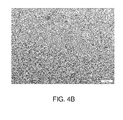
- Figures 4A and 4B are optical micrographs illustrating the microstructure of the pipe after quenching and tempering according to the disclosed embodiments, where the soaking time is approximately 2400 s.
- Figure 4A shows an optical micrograph at low magnification (e.g., about 200x)
- Figure 4B shows an optical micrograph at high magnification (e.g., about 1000x), illustrating the microstructure of an as-quenched pipe after selective etching able to reveal the boundaries of the prior austenite grains.
- the prior austenite grain size is large, approximately 47 ⁇ m and hardenability may be further improved with a volume percentage of martensite greater than about 90%.
- the average size of regions separated by high angle grain boundaries is approximately smaller than 6 ⁇ m.
- the packet size of the steel after quenching and tempering may be maintained below approximately 6 ⁇ m if a predominant martensite structure (e.g., martensite greater than about 60% in volume) is formed and lower bainite forms at relatively low temperatures (e.g., ⁇ 540°C).
- a predominant martensite structure e.g., martensite greater than about 60% in volume
- lower bainite forms at relatively low temperatures (e.g., ⁇ 540°C).
- Packet size may be measured as average lineal intercept on images taken by Scanning Electron Microscopy (SEM) using the Electron Back Scattered Diffraction (EBSD) signal, and considering high-angle boundaries those with misorientation greater than about 45°.
- SEM Scanning Electron Microscopy
- EBSD Electron Back Scattered Diffraction
- Boundary misorientation less than about 3° are indicated as fine lines, while boundaries exhibiting a misorientation greater than about 45° are indicated as bold lines.
- fine precipitates of MX, M 2 X type (where M is Mo or Cr, or V, Nb, Ti when present, and X is C or N) with size less than about 40 nm were also detected by Transmission Electron Microscopy (TEM), in addition to coarse precipitates of the type M 3 C, M 6 C, and/or M 23 C 6 , with an average diameter within the range between about 80 nm to about 400 nm.
- TEM Transmission Electron Microscopy
- the total volume percentage of non-metallic inclusions is below about 0.05%, preferably below about 0.04%.
- the number of inclusions per square mm of examined area of oxides with size larger than about 15 ⁇ m is below about 0.4/mm 2 . Substantially only modified round sulfides are present.
- microstructural and mechanical properties and impact of steel pipes formed using embodiments of the steel making method discussed above are discussed.
- microstructural parameters including austenite grain size, packet size, martensite volume, lower bainite volume, volume of non-metallic inclusions, and inclusions of greater than about 15 ⁇ m are examined for embodiments of the compositions and heat treatment conditions discussed above.
- Corresponding mechanical properties including yield and tensile strengths, hardness, elongation, toughness, and HIC/SSC resistance are further discussed.
- the microstructural and mechanical properties of the steel of Table 2 were investigated.
- austenite grain size was measured in accordance with ASTM E112
- packet size was measured using an average lineal intercept on images taken by scanning electron microscopy (SEM) using the electron backscatter diffraction (EBSD) signal
- the volume of martensite was measured in accordance with
- the volume of lower bainite was measured in accordance with ASTM E562
- the volume percentage of non-metallic inclusions was measured by automatic image analysis using optical microscopy in accordance with ASTM E1245
- the presence of precipitates was investigated by transmission electron microscopy (TEM) using the extraction replica method.
- TEM transmission electron microscopy
- yield strength, tensile strength, and elongation were measured in accordance with ASTM E8, hardness was measured in accordance with ASTM E92, impact energy was evaluated on transverse Charpy V-notch specimens according to ISO 148-1, crack tip opening displacement was measured according to BS7488 part 1 at about - 60°C, HIC evaluation was performed in accordance with NACE Standard TM0284-2003, Item No. 21215 using NACE solution A and a test duration of 96 hours. SSC evaluation was performed in accordance with NACE TM0177 using test solution A and a test duration of about 720 hours at about 90% specified minimum yield stress.
- Table 2 Chemical composition range of Example 1 C Mn Si P S Ni Cr Mo Ca V Nb Ti N Cu Al As Sb Sn B H Min 0.10 0.40 0.20 - - - 1.9 0.9 0.001 0.05 - - - - 0.010 - - - - Max 0.13 0.55 0.35 0.015 0.009 0.20 2.3 1.1 0.005 0.07 0.010 0.01 0.012 0.20 0.020 0.02 0.005 0.015 0.001, 0.0003
- the as-cast bars were re-heated by a rotary heath furnace to a temperature of about 1300°C, hot pierced, and the hollows were hot rolled by a retained mandrel multi-stand pipe mill and subjected to hot sizing in accordance process described above with respect to Figure 1 .
- the produced seamless pipes possessed an outside diameter of about 273.2 mm and a wall thickness of about 13.9 mm.
- the chemical composition measured on the resultant as-rolled seamless pipe is reported in Table 3.
- the as-rolled pipes were subsequently austenitized by heating to a temperature of about 920°C for approximately 2200 s by a walking beam furnace, descaled by high pressure water nozzles, and externally and internally water quenched using a tank with stirred water and an inner water nozzle.
- the austenitizing heating rate was approximately 0.25°C/s.
- the cooling rate employed during quenching was approximately greater than 65°C/s.
- the quenched pipes were rapidly moved to another walking beam furnace for tempering treatment at a temperature of about 710 °C for a total time of about 5400 s and a soaking time of about 1800 s.
- the tempering heating rate was approximately 0.2°C/s.
- the cooling employed after tempering was performed in still air at a rate approximately below 0.5°C/s. All the quenched and tempered (Q&T) pipes were hot straightened.
- Table 4 The main parameters characterizing the microstructure and non-metallic inclusions of the pipes of Example 1 are shown in Table 4.
- Table 4 Microstructural parameters of seamless pipes of example 1 Parameter Average value Austenite grain size ( ⁇ m) 47 Packet size ( ⁇ m) 5.1 Martensite (volume %) 100 Lower Bainite (volume %) 0 Volume of non metallic inclusions (%) 0.03 Inclusions with size > 15 ⁇ m (No./mm 2 ) 0.2
- the mechanical and corrosion properties of the pipes of Example 1 are shown in Tables 5, 6, and 7.
- Table 5 presents the tensile, elongation, hardness, and toughness properties of the quenched and tempered pipes.
- Table 6 presents the yield strength after two simulated post-weld heat treatments, PWHT1 and PWHT2.
- the post-weld heat treatment 1 comprised heating and cooling at a rate of about 80°C/h to a temperature of about 650°C with a soaking time of about 5 h.
- the post-weld heat treatment 2 comprised heating and cooling at a rate of about 80°C/h to a temperature of about 650°C with a soaking time of about 10 h.
- Table 7 presents the measured HIC and SSC resistance of the quenched and tempered pipes.
- Table 5 Mechanical properties of quenched and tempered pipes of Example 1 Mechanical Property Result Average Yield Strength (MPa) 615 Minimum Yield Strength (MPa) 586 Maximum Yield Strength (MPa) 633 Average Ultimate Tensile Strength, UTS (MPa) 697 Minimum Ultimate Tensile Strength, UTS (MPa) 668 Maximum Ultimate Tensile Strength, UTS (MPa) 714 Maximum YS/UTS ratio 0.91 Average Elongation (%) 22.1 Minimum Elongation (%) 20.5 Maximum Elongation (%) 25.8 Maximum Hardness (HV 10 ) 232 Average Impact Energy (J) at about -70 °C [transverse CVN specimens] 250 Individual Minimum Impact Energy (J) at about -70 °C [transverse CVN specimens] 200 80% FATT (°C) [transverse CVN specimens] - 90 50% FATT (°C) [transverse CVN specimens] - 110 Average CTOD (mm) at
- Example 8 The microstructural and mechanical properties of the steel of Table 8 were investigated as discussed above with respect to Example 1.
- Table 8 - Chemical composition of the heat of Example 2 C Mn Si P S Ni Cr Mo Ca V Nb Ti N Cu Al As Sb Sn B H 0.11 0.41 0.24 0.010 0.002 0.09 2.22 0.91 0.012 0.06 0.005 0.002 0.0074 0.10 0.01 0.005 0.0018 0.009 0.0001 0.0002
- the as-cast bars were re-heated by a rotary heath furnace to a temperature of about 1300°C, hot pierced, and the hollows were hot rolled by a retained mandrel multi-stand pipe mill and subjected to hot sizing in accordance process described above with respect to Figure 1 .
- the produced seamless pipes possessed an outside diameter of about 250.8 mm and a wall thickness of about 15.2 mm.
- the chemical composition measured on the resultant as-rolled seamless pipe is reported in Table 9.
- the as-rolled pipes were subsequently austenitized by heating to a temperature of about 900°C for approximately 2200 s by a walking beam furnace, descaled by high pressure water nozzles, and externally and internally water quenched using a tank with stirred water and an inner water nozzle.
- the austenitizing heating rate was approximately 0.2°C/s.
- the cooling rate employed during quenching was approximately greater than 60°C/s.
- the quenched pipes were rapidly moved to another walking beam furnace for tempering treatment at a temperature of about 680°C for a total time of about 5400s and a soaking time of about 1800s.
- the tempering heating rate was approximately 0.2°C/s.
- the cooling employed after tempering was performed in still air at a rate approximately below 0.5°C/s. All the quenched and tempered (Q&T) pipes were hot straightened.
- Table 10 The main parameters characterizing the microstructure and non-metallic inclusions of the pipes of Example 2 are shown in Table 10.
- Table 10 Microstructural parameters of seamless pipes of Example 2 Parameter Average value Austenite grain size ( ⁇ m) 26.2 Packet size ( ⁇ m) 3.8 Martensite (volume %) 95 Lower Bainite (volume %) 5 Volume of non metallic inclusions (%) 0.028 Inclusions with size > 15 ⁇ m (No./mm 2 ) 0.45
- Table 11 presents the tensile, elongation, hardness, and toughness properties of the quenched and tempered pipes.
- Tests were conducted in accordance with NACE TM0177 method A, using test solution A, with a stress value greater than or equal to about 72% of specified minimum yield strength (SMYS) at about 1 bar H 2 S pressure.
- STYS specified minimum yield strength
- the produced seamless pipes were austenitized at about 920°C for approximately 2200 s, as discussed above, by a walking beam furnace.
- the pipes were further descaled by high pressure water nozzles and externally and internally water quenched using a tank with stirred water and an inner water nozzle.
- the quenched pipes were rapidly moved to another walking beam furnace for tempering treatment at about 660-670°C. All the quenched and tempered pipes were hot straightened.
- these quenched and tempered pipes as they are manufactured with a steel that has a fine austenite grain (about 12 ⁇ m), does not develop enough hardenability to form martensite. Therefore, the microstructure exhibits a predominant granular bainite microstructure, including some lower bainite and also some amount of coarse ferrite (see Fig.7 and Table 13). Moreover, the packet size is larger than that of the examples 1 and 2.
- the quenched and tempered pipes of Example 1 were used to manufacture bends having a radius of approximately 5 times the outer diameter of the pipe (5D).
- the pipes were subjected to hot induction bending by heating to a temperature of approximately 850°C +/- 25 °C and in-line water quenching.
- the bends were then reheated to a temperature of about 920°C for approximately 15 min holding in a car furnace, moved to a water tank, and immersed in stirred water.
- the minimum temperature of the bends was higher than about 860°C just before immersion in the water tank and the temperature of the water of the tank was maintained below approximately 40°C.
- the as-cast bars were re-heated by a rotary heath furnace to a temperature of about 1300°C, hot pierced, and the hollows were hot rolled by a retained mandrel multi-stand pipe mill and subjected to hot sizing in accordance process described above with respect to Figure 1 .
- the produced seamless pipes possessed an outside diameter of about 273.1 mm and a wall thickness of about 33 mm.
- the chemical composition measured on the resultant as-rolled seamless pipe is reported in Table 18.
- the as-rolled pipes were subsequently austenitized by heating to a temperature of about 920°C for approximately 5400 s by a walking beam furnace, descaled by high pressure water nozzles, and externally and internally water quenched using a tank with stirred water and an inner water nozzle.
- the austenitizing heating rate was approximately 0.16°C/s.
- the cooling rate employed during quenching was approximately 25°C/s.
- the quenched pipes were rapidly moved to another walking beam furnace for tempering treatment at a temperature of about 750°C for a total time of about 8600 s and a soaking time of about 4200 s.
- the tempering heating rate was approximately 0.15°C/s.
- the cooling rate employed during tempering was approximately less than 0.1°C/s. All the quenched and tempered (Q&T) pipes were hot straightened.
- the mechanical properties and corrosion resistance of the pipes of Example 5 are shown in Table 19 and Table 20, respectively.
- Table 20 presents the tensile, elongation, hardness, and toughness properties of the quenched and tempered pipes.
- Table 19 - Mechanical properties of quenched and tempered pipes of Example 5 Mechanical Property Result Average Yield Strength (MPa) 514 Minimum Yield Strength (MPa) 494 Maximum Yield Strength (MPa) 545 Average Ultimate Tensile Strength, UTS (MPa) 658 Minimum Ultimate Tensile Strength, UTS (MPa) 646 Maximum Ultimate Tensile Strength, UTS (MPa) 687 Maximum YS/UTS ratio (-) 0.83 Average Elongation (%) 22.2 Minimum Elongation (%) 20.6 Maximum Elongation (%) 24.2 Maximum Hardness (HV 10 ) 218 Average Impact Energy (J) at about -70°C [transverse CVN specimens] 270 Individual Minimum Impact Energy (J) at about -70°C [transverse CVN specimens] 200 80% FATT (°C
Abstract
Description
- The present invention relates generally to metal production and, in certain embodiments, relates to methods of producing metallic tubular bars having high toughness at low temperature while concurrently possessing sulfide stress corrosion cracking resistance. Certain embodiments relate to seamless steel pipes for risers of all kinds (catenary, hybrid, top tension, work over, drilling, etc), line pipes and flow lines for use in the oil and gas industry, including pipes that are suitable for bending.
- A core component in deep and ultra-deep sea production is the circulation of fluids from the seafloor to the surface system. Risers, the pipes which connect the drilling or production platform to the well, are exposed over considerable length (now exceeding roughly 10,000 feet, or approximately 2 miles) to the straining pressures of multiple ocean currents.
- Riser system costs are quite sensitive to water depth. Although in-service conditions and the sensitiveness of environmental loads (i.e. wave and current) are different for the for the different riser types - Top Tension Risers (TTRs) and Steel Catenary Risers (SCRs), Hybrid Risers (HRs), Work over (WORs) and Drilling Risers (DRs) - reducing the raiser weight may provide significant benefits. For example, by reducing the weight of the line, it is anticipated that a decrease in the cost of the pipe and a significant impact on the tensioning system used to support the riser may be achieved. For at least these reasons, high strength steels, with yield stresses of 70 ksi (485 MPa) and above, are candidates for development of lighter risers in the offshore sector.
- However, steels with specified minimum yield strength (SMYS) exceeding 70 ksi can suffer sulfide stress corrosion (SSC) induced failures as a result of hydrogen embrittlement under stress. Therefore, it is difficult to meet the NACE requirement for sour service materials (e.g., NACE MR0175/ISO 15156-1 "Petroleum and natural gas industries—Materials for use in H2S-containing Environments in oil and gas production—Part 1: General principles for selection of cracking-resistant materials) and to pass SSC testing (e.g., NACE Standard TM0177 "Laboratory testing of metals for resistance to sulfide stress cracking and stress corrosion cracking in H2S environments").
- While major seamless line pipe manufacturers are able to manufacture high strength materials with minimum yield strength equal or above 70 ksi, resistance to SSC and hydrogen induced cracking (HIC) (this latter assessed according with NACE Standard TM0284, "Evaluation of pipeline and pressure vessel steels for resistance to hydrogen induced cracking") of these high grades is often not adequate. Currently, only grades up to X70 are rated for sour service according to ISO 3183.
- Moreover, increased strength may lead to more brittle behavior at lower temperatures. In general the materials are qualified at so-called "design temperatures", which typically lie at about 20°C below minimum expected service and/or ambient temperature. The lowest ambient temperature on the Norwegian continental shelf is about -20°C. In the Arctic regions, minimum ambient temperatures well below -40°C are expected. Consequently, minimum design temperatures down to approximately -60°C are desired.
- However, line pipe steels with yield stresses of about 70 ksi and above are today qualified for design temperatures only down to about -40°C. This limitation could limit cost-effective oil and gas exploration in arctic and arctic-like regions. Therefore new high strength steel pipes with improved toughness at temperatures equal or less than about -60°C are desirable.
- Embodiments of the invention are directed to steel pipes or tubes and methods of manufacturing the same. In some embodiments, seamless quenched and tempered steel pipes for riser and line pipes are provided having wall thickness (WT) between 8 to 35 mm with a minimum yield strength of 70 ksi, 80 ksi, and 90 ksi, respectively, with excellent low temperature toughness and corrosion resistance (sour service, H2S environment). The seamless pipes are also suitable to produce bends of the same grade by hot induction bending and off-line quenching and tempering treatment. In one embodiment, the steel pipe has an outside diameter (OD) between 6" (152 mm) and 28" (711 mm), and wall thickness (WT) from 8 to 35 mm.
- In one embodiment, the composition of a seamless, low-alloy steel pipe consists of (by weight): 0.05%-0.16% C, 0.20%-0.90% Mn, 0.10%-0.50% Si, 1.20%-2.60% Cr, 0.05%-0.50% Ni, 0.80%-1.20% Mo, 0.03% Nb max, 0.02% Ti max, 0.005%-0.12% V, 0.008%-0.040% Al, 0.0030-0.012% N, 0.3% Cu max, 0.01% S max, 0.02% P max, 0.001-0.005% Ca, 0.0020% B max, 0.020% As max, 0.0050% Sb max, 0.020% Sn max, 0.030% Zr max, 0.030% Ta max, 0.0050% Bi max, 0.0030% O max, 0.00030% H max, with the balance being iron and inevitable impurities.
- The steel pipes may be manufactured into different grades. In one embodiment, a 70 ksi grade is provided with the following properties:
- ● Yield strength, YS: 485 MPa (70 ksi) minimum and 635 MPa (92 ksi) maximum
- ● Ultimate Tensile Strength, UTS: 570 MPa (83 ksi) minimum and 760 MPa (110 ksi) maximum
- ● Elongation, not less that 20%.
- ● YS/UTS ratio no higher than 0.93.
- In another embodiment, an 80 ksi grade is provided with the following properties:
- ● Yield strength, YS: 555 MPa (80 ksi) minimum and 705 MPa (102 ksi) maximum
- ● Ultimate Tensile Strength, UTS: 625 MPa (90 ksi) minimum and 825 MPa (120 ksi) maximum.
- ● Elongation, not less that 20%.
- ● YS/UTS ratio no higher than 0.93.
- In another embodiment, a 90 ksi grade is provided with the following properties:
- ● Yield strength, YS: 625 MPa (90 ksi) minimum and 775 MPa (112 ksi) maximum
- ● Ultimate Tensile Strength, UTS: 695 MPa (100 ksi) minimum and 915 MPa (133 ksi) maximum
- ● Elongation, not less that 18%.
- ● YS/UTS ratio no higher than 0.95.
- The steel pipe may have a minimum impact energy of 250 J / 200 J (average / individual) and minimum 80% of average shear area for both longitudinal and transverse Charpy V-notch (CVN) tests performed at about -70°C according with standard ISO 148-1. In one embodiment, the 80 ksi grade pipe may have a hardness of 248 HV10 maximum. In another embodiment, the 90 ksi grade pipe may have a hardness of 270
HV 10 maximum. - Steel pipes manufactured according to embodiments of the invention may exhibit resistance to both hydrogen induced cracking (HIC) and sulfide stress corrosion (SSC) cracking. In one embodiment, HIC test performed according with NACE Standard TM0284-2003 Item No. 21215, using NACE solution A and test duration 96 hours, provides the following HIC parameters (average on three sections of three specimens):
- ● Crack Length Ratio, CLR ≤ 5%
- ● Crack Thickness Ratio, CTR ≤ 1%
- ● Crack Sensitivity Ratio, CSR ≤ 0.2%
- In another embodiment, SSC testing performed in accordance with NACE TM0177, using test solution A, test duration 720 hours, provides no failure at 90% of SMYS for grades 70 ksi and 80 ksi and no failure at 72% SMYS for 90 ksi grade.
- Steel pipes manufactured according to certain embodiments of the invention have a microstructure exhibiting no ferrite, no upper bainite, and no granular bainite. They may be constituted of tempered martensite with a volume percentage greater than 60%, preferably greater than 90%, most preferably greater than 95% (measured according with ASTM E562-08) and tempered lower bainite with volume percentage less than 40%, preferably less than 10%, most preferably less than 5%. Martensite and bainite may be formed at temperatures lower than 450 °C and 540 °C respectively, after re-heating at temperatures of 900°C to 1060°C for soaking times from 300 s to 3600 s, and quenching at cooling rates greater than 20°C/s. The average prior austenite grain size measured by ASTM E112 standard is greater than 15 µm or 20 µm (lineal intercept) and smaller than 100 µm.
- In further embodiments, the packet size of the steel pipes after tempering may possess a packet size (i.e., the average size of regions separated by high angle boundaries smaller than 6 µm. In further embodiments, the packet size may be smaller than about 4 µm. In other embodiments, the packet size may be smaller than about 3 µm. Packet size may be measured as the average lineal intercept on images taken by Scanning Electron Microscopy (SEM) using the Electron Back Scattered Diffraction (EBSD) signal, with high-angle boundaries considered to be those boundaries with a misorientation > 45°.
- In additional embodiments, the steel pipes after tempering may exhibit the presence of fine and coarse precipitates. The fine precipitates may be of the type MX, M2X, where M is V, Mo, Nb, or Cr and X is C or N. The average diameter of the fine precipitates may be less than about 40 nm. The coarse precipitates may be of the type M3C, M6C, M23C6. The average diameter of the coarse precipitates may be within the range between about 80 nm to about 400 nm. The precipitates may be examined by Transmission Electron Microscopy (TEM) using the extraction replica method.
- In an embodiment, a steel pipe is provided. The steel pipe comprises a steel composition comprising:
- about 0.05 wt. % to about 0.16 wt. % carbon;
- about 0.20 wt. % to about 0.90 wt. % manganese;
- about 0.10 wt. % to about 0.50 wt. % silicon;
- about 1.20 wt. % to about 2.60 wt. % chromium;
- about 0.05 wt. % to about 0.50 wt. % nickel;
- about 0.80 wt.% to about 1.20 wt.% molybdenum;
- about 0.005 wt. % to about 0.12 wt. % vanadium
- about 0.008 wt. % to about 0.04 wt. % aluminum;
- about 0.0030 wt. % to about 0.0120 wt. % nitrogen; and
- about 0.0010 wt. % to about 0.005 wt. % calcium;
- The wall thickness of the steel pipe may be greater than or equal to about 8 mm and less than about 35 mm. The steel pipe may be processed to have a yield strength greater than about 70 ksi and the microstructure of the steel tube may comprise martensite in a volume percentage greater than or equal to about 60 % and lower bainite in a volume percentage less than or equal to about 40 %
- In another embodiment, a method of making a steel pipe is provided. The method comprises providing a steel having a steel composition (e.g., a low-alloy steel). The method further comprises forming the steel into a tube having a wall thickness greater than or equal to about 8 mm and less than about 35 mm. The method additionally comprises heating the formed steel tube in a first heating operation to a temperature within the range between about 900°C to about 1060°C. The method also comprises quenching the formed steel tube at a cooling rate greater than or equal to about 20°C/sec, wherein the microstructure of the quenched steel is greater than or equal to about 60% martensite and less than or equal to about 40% lower bainite and has an average prior austenite grain size measured by ASTM E112 greater than about 15 µm. The method additionally comprises tempering the quenched steel tube at a temperature within the range between about 680°C to about 760°C, wherein the steel tube after tempering has a yield strength greater than about 70 ksi and an average Charpy V-notch energy greater or equal to about 150 J/cm2 at about -70°C. In other embodiments, the average Charpy V-notch energy of the steel tube is greater or equal to about 250 J/cm2 at about -70°C.
- In an embodiment, an 80 ksi grade seamless steel pipe is provided. The pipe, comprises:
- a steel composition comprising:
- 0.10 wt. % to 0.13 wt. % carbon;
- 0.40 wt. % to 0.55 wt. % manganese;
- 0.20 wt. % to 0.35 wt. % silicon;
- 1.9 wt. % to 2.3 wt. % chromium;
- 0.9 wt. % to 1.1 wt. % molybdenum;
- 0.001 wt. % to 0.005 wt. % calcium;
- 0.05 wt. % to 0.07 wt. % vanadium; and
- 0.010 wt. % to 0.020 wt. % aluminum;
- The wall thickness of the steel pipe may be greater than or equal to about 8 mm and less than or equal to about 35 mm. The steel pipe may be processed by hot rolling followed by cooling to room temperature, heating to a temperature of about 900°C or above, quenching at a cooling rate greater than or equal to 40°C/sec, and tempering at a temperature between about 680°C to about 760°C, to form a microstructure having a prior austenite grain size of about 20 µm to about 80 µm, a packet size of about 3 µm to about 6 µm, and about 90% martensite by volume or greater, and about 10% lower bainite by volume or less. The steel pipe may have a yield strength (YS) between about 80 ksi and about 102 ksi, an ultimate tensile strength (UTS) between about 90 ksi and about 120 ksi, elongation no less than about 20%, and YS/UTS ratio no higher than about 0.93.
- In another embodiment, a 90 ksi grade seamless steel pipe may be provided. The pipe, comprises:
- a steel composition comprising:
- 0.10 wt. % to 0.13 wt. % carbon;
- 0.40 wt. % to 0.55 wt. % manganese;
- 0.20 wt. % to 0.35 wt. % silicon;
- 1.9 wt. % to 2.3 wt. % chromium;
- 0.9 wt. % to 1.1 wt. % molybdenum;
- 0.001 wt. % to 0.005 wt. % calcium;
- 0.05 wt. % to 0.07 wt. % vanadium; and
- 0.010 wt. % to 0.020 wt. % aluminum;
- The wall thickness of the steel pipe may be greater than or equal to about 8 mm and less than or equal to about 35 mm. The steel pipe may be processed by hot rolling followed by cooling to room temperature, heating to a temperature of about 900°C or above, quenching at a cooling rate greater than or equal to about 20°C/sec, and tempering at a temperature between about 680°C to about 760°C, to form a microstructure having a prior austenite grain size of about 20 µm to about 60 µm, a packet size of about 2 µm to about 6 µm, and about 95% martensite by volume or greater, and about 5% lower bainite by volume or less. The steel pipe may have a yield strength (YS) between about 90 ksi and about 112 ksi, an ultimate tensile strength (UTS) between 100 ksi and 133 ksi, elongation no less than about 18%, and YS/UTS ratio no higher than about 0.95.
- In a further embodiment, a 70 ksi grade seamless steel pipe may be provided. The pipe comprises:
- a steel composition comprising:
- 0.10 wt. % to 0.13 wt. % carbon;
- 0.40 wt. % to 0.55 wt. % manganese;
- 0.20 wt. % to 0.35 wt. % silicon;
- 2.0 wt. % to 2.5 wt. % chromium;
- 0.9 wt. % to 1.1 wt. % molybdenum; and
- 0.001 wt. % to 0.005 wt. % calcium;
- The wall thickness of the steel pipe may be greater than or equal to about 8 mm and less than or equal to about 35 mm. The steel pipe may be processed by hot rolling followed by cooling to room temperature, heating to a temperature of about 900°C or above, quenching at a cooling rate greater than or equal to about 20°C/sec, and tempering at a temperature between about 680°C to about 760°C, to form a microstructure having a prior austenite grain size of about 20 µm to about 100 µm, a packet size of about 4 µm to about 6 µm, and about 60% martensite by volume or greater, and about 40% lower bainite by volume or less. The steel pipe may have a yield strength (YS) between about 70 ksi and about 92 ksi, an ultimate tensile strength (UTS) between about 83 ksi and about 110 ksi, elongation no less than about 18%, and YS/UTS ratio no higher than about 0.93.
- Other features and advantages of the invention will be apparent from the following description taken in connection with the accompanying drawings.
-
Figure 1 is a schematic flow diagram illustrating one embodiment of a method for fabricating steel pipes; -
Figure 2 is an embodiment of a continuous cooling transformation (CCT) diagram for an embodiment of a steel of the present disclosure; -
Figure 3 is an optical micrograph of an as-quenched pipe formed according to the disclosed embodiments using a hold time of about 600 s. The pipe is etched to illustrate the prior austenite grain boundaries; -
Figure 4A and4B are optical micrographs of an as-quenched and tempered pipe formed according to the disclosed embodiments using a hold time of about 2400 s. The pipe is etched to illustrate the prior austenite grain boundaries. (4A) 200x magnification; (4B) 1000x magnification; -
Figure 5 is a micrograph taken by Scanning Electron Microscopy (SEM) using the Electron Back Scattered Diffraction (EBSD) signal, illustrating boundaries with low and high misorientation at about the mid-wall of the pipe ofFigure 4 ; -
Figure 6 is a plot illustrating the intercept distribution of boundaries with misorientation angle greater than about 45° for a steel formed according the disclosed embodiments; and -
Figure 7 is an optical micrograph at about the mid-wall of the as-quenched pipe of the comparative example of Example 3. - Embodiments of the present disclosure provide steel compositions, tubular bars (e.g., pipes) formed using the steel compositions, and respective methods of manufacture. The tubular bars may be employed, for example, as line pipes and risers for use in the oil and gas industry. In certain embodiments, the tubular bars may possess wall thicknesses greater than or equal to about 8 mm and less than about 35 mm and a microstructure of martensite and lower bainite without substantial ferrite, upper bainite, or granular bainite. So formed, the tubular bars may possess a minimum yield strength of about 70 ksi, 80 ksi, and about 90 ksi. In further embodiments, the tubular bars may possess good toughness at low temperatures and resistance to sulfide stress corrosion cracking (SSC) and hydrogen induced cracking (HIC), enabling use of the tubular bars in sour service environments. It may be understood, however, that tubular bars comprise one example of articles of manufacture which may be formed from embodiments of the present disclosure and should in no way be construed to limit the applicability of the disclosed embodiments.
- The term "bar" as used herein is a broad term and includes its ordinary dictionary meaning and also refers to a generally hollow, elongate member which may be straight or have bends or curves and be formed to a predetermined shape, and any additional forming required to secure the formed tubular bar in its intended location. The bar may be tubular, having a substantially circular outer surface and inner surface, although other shapes and cross-sections are contemplated as well. As used herein, the term "tubular" refers to any elongate, hollow shape, which need not be circular or cylindrical.
- The terms "approximately," "about," and "substantially," as used herein represent an amount close to the stated amount that still performs a desired function or achieves a desired result. For example, the terms "approximately," "about," and "substantially" may refer to an amount that is within less than 10% of, within less than 5% of, within less than 1% of, within less than 0.1% of, and within less than 0.01% of the stated amount.
- The term "room temperature" as used herein has its ordinary meaning as known to those skilled in the art and may include temperatures within the range of about 16°C (60°F) to about 32°C (90°F).
- Embodiments of the present disclosure comprise low-alloy carbon steel pipes and methods of manufacture. As discussed in greater detail below, through a combination of steel composition and heat treatment, a final microstructure may be achieved that gives rise to selected mechanical properties of interest, including one or more of minimum yield strength, toughness, hardness and corrosion resistance, in high wall thickness pipes (e.g., WT greater than or equal to about 8 mm and less than about 35 mm).
- The steel composition of the present disclosure may comprise not only carbon (C) but also manganese (Mn), silicon (Si), chromium (Cr), nickel (Ni), molybdenum (Mo), vanadium (V), aluminum (Al), nitrogen (N), and calcium (Ca). Additionally, one or more of the following elements may be optionally present and/or added as well: tungsten (W), niobium (Nb), titanium (Ti), boron (B), zirconium (Zr), and tantalum (Ta). The remainder of the composition may comprise iron (Fe) and impurities. In certain embodiments, the concentration of impurities may be reduced to as low an amount as possible. Embodiments of impurities may include, but are not limited to, copper (Cu), sulfur (S), phosphorous (P), arsenic (As), antimony (Sb), tin (Sn), bismuth (Bi), oxygen (O), and hydrogen (H).
- For example, the low-alloy steel composition may comprise (in weight % unless otherwise noted):
- Carbon within the range between about 0.05% to about 0.16%;
- Manganese within the range between about 0.20% to about 0.90%;
- Silicon within the range between about 0.10% to about 0.50%;
- Chromium within the range between about 1.20% to about 2.60%;
- Nickel within the range between about 0.050% to about 0.50%;
- Molybdenum within the range between about 0.80% to about 1.20%;
- Tungsten less than or equal to about 0.08%
- Niobium less than or equal to about 0.030%;
- Titanium less than or equal to about 0.020%;
- Vanadium within the range between about 0.005% to about 0.12%;
- Aluminum within the range between about 0.008% to about 0.040%;
- Nitrogen within the range between about 0.0030% to about 0.012%;
- Copper less than or equal to about 0.3%;
- Sulfur less than or equal to about 0.01%;
- Phosphorous less than or equal to about 0.02%;
- Calcium within the range between about 0.001 to about 0.005%;
- Boron less than or equal to about 0.0020%;
- Arsenic less than or equal to about 0.020%;
- Antimony less than or equal to about 0.005%;
- Tin less than or equal to about 0.020%;
- Zirconium less than or equal to 0.030%;
- Tantalum less than or equal to 0.030%;
- Bismuth less than about 0.0050%;
- Oxygen less than about 0.0030%;
- Hydrogen less than or equal to about 0.00030%; and
- the balance of the composition comprising iron and impurities.
- The heat treatment operations may include quenching and tempering (Q+T). The quenching operation may include reheating a pipe from about room temperature after hot forming to a temperature that austenitizes the pipe followed by a rapid quench. For example, the pipe may be heated to a temperature within the range between about 900°C to about 1060°C and held at about the austenitizing temperature for a selected soaking time. Cooling rates during the quench are selected so as to achieve a selected cooling rate at about the mid-wall of the pipe. For example, pipes may be cooled so as to achieve cooling rates greater than or equal to about 20°C/s at the mid-wall. In other embodiments, the cooling rate may be greater than or equal to about 40°C/sec, as discussed in greater detail below.
- Quenching pipes having a WT greater than or equal to about 8 mm and less than about 35 mm and the composition described above may promote the formation of a volume percent of martensite greater than about 60%, preferably greater than about 90% and more preferably greater than about 95% within the pipe. In certain embodiments, the remaining microstructure of the pipe may comprise lower bainite, with substantially no ferrite, upper bainite, or granular bainite. In other embodiments, the microstructure of the pipe may comprise substantially 100% martensite.
- Following the quenching operations, the pipe may be further subjected to tempering. Tempering may be conducted at a temperature within the range between about 680°C to about 760°C, depending upon the composition of the steel and the target yield strength. In addition to the martensite and lower bainite, the microstructure may further exhibit an average prior austenite grain size measured according to ASTM E112 of between about 15 µm to about 100 µm. The microstructure may also exhibit an average packet size of less than or equal to about 6 µm, preferably less than or equal to about 4 µm, most preferably less than or equal to about 3 µm. The microstructure may further exhibit fine precipitates of MX, M2X, where M = V, Mo, Nb, Cr and X = C or N having an average diameter less than or equal to about 40 nm and coarse precipitates of the type M3C, M6C, and M23C6 with an average diameter within the range between about 80 to about 400 nm.
- In one embodiment, a steel pipe having a WT greater than or equal to about 8 mm and less than about 35 mm and the composition and microstructure discussed above may possess the following properties:
● Minimum Yield Strength (YS) = about 70 ksi (485 MPa) ● Maximum Yield Strength = about 102 ksi (705 MPa) ● Minimum Ultimate Tensile Strength (UTS) = about 90 ksi (625 MPa) ● Maximum Ultimate Tensile Strength = about 120 ksi (825 MPa) ● Elongation at failure = Greater than about 20% ● YS/UTS = Less than or equal to about 0.93 - In another embodiment, a steel pipe having a WT greater than or equal to about 8 mm and less than about 35 mm and the composition and microstructure discussed above may possess the following properties:
● Minimum Yield Strength (YS) = about 80 ksi (550 MPa) ● Maximum Yield Strength = about 102 ksi (705 MPa) ● Minimum Ultimate Tensile Strength (UTS) = about 90 ksi (625 MPa) ● Maximum Ultimate Tensile Strength = about 120 ksi (825 MPa) ● Elongation at failure = Greater than about 20% ● YS/UTS = Less than or equal to about 0.93 - In another embodiment, a steel pipe having a WT greater than or equal to about 8 mm and less than about 35 mm may be formed having the following properties:
● Minimum Yield Strength (YS) = about 90 ksi (625 MPa) ● Maximum Yield Strength = about 112 ksi (775 MPa) ● Minimum Ultimate Tensile Strength (UTS) = about 100 ksi (695 MPa) ● Maximum Ultimate Tensile Strength = about 133 ksi (915 MPa) ● Elongation at failure = Greater than about 18% ● YS/UTS = Less than or equal to about 0.95 - In each of the above embodiments, formed pipe may further exhibit the following impact and hardness properties:
● Minimum Impact Energy (Average/Individual at about -70°C): ● = about 250 J/ about 200 J (for 70 ksi and 80 ksi grades) ● = about 150 J/ about 100 J (for 90 ksi grade) ● Average Shear Area (CVN at about -70°C; ISO 148-1) ● = about 80% minimum ● Hardness ● = about 248 HV10 maximum (for 70 ksi and 80 ksi grades) ● = about 270 HV10 maximum (for 90 ksi grade) - In each of the above embodiments, formed pipe may further exhibit the following resistance to sulfide stress corrosion (SSC) cracking and hydrogen induced cracking (HIC). SSC testing is conducted according to NACE TM 0177 using solution A with a test duration of about 720 hours. HIC testing is conducted according to NACE TM 0284-2003 Item 21215 using NACE solution A and test duration 96 hours:
HIC:● Crack Length Ratio, CLR = Less than or equal to 5% ● Crack Thickness Ratio, CTR = Less than or equal to 1% ● Crack Sensitivity Ratio, CSR = Less than or equal to 0.2% ● Failure time at 90% specified minimum yield stress ● = For 70 ksi and 80 ksi grades, greater than about 720 hours ● Failure time at 72% specified minimum yield stress ● = For 90 ksi grade, greater than about 720 hours - With reference to
Figure 1 , a flow diagram illustrating one embodiment of amethod 100 for manufacturing tubular bars is shown. Themethod 100 includessteel making operations 102, hot formingoperations 104,heat treatment operations 106, which may includeaustenitizing 106A, quenching 106B, tempering 106C, and finishingoperations 110. It may be understood that themethod 100 may include greater or fewer operations and the operations may be performed in a different order than that illustrated inFigure 1 , as necessary. -
Operation 102 of themethod 100 preferably comprises fabrication of the steel and production of a solid metal billet capable of being pierced and rolled to form a metallic tubular bar. In further embodiments, selected steel scrap, cast iron, and sponge iron may be employed to prepare the raw material for the steel composition. It may be understood, however, that other sources of iron and/or steel may be employed for preparation of the steel composition. Primary steelmaking may be performed using an electric arc furnace to melt the steel, decrease phosphorous and other impurities, and achieve a selected temperature. Tapping and deoxidation, and addition of alloying elements may be further performed. - One of the main objectives of the steelmaking process is to refine the iron by removal of impurities. In particular, sulfur and phosphorous are prejudicial for steel because they degrade the mechanical properties of the steel. In one embodiment, secondary steelmaking may be performed in a ladle furnace and trimming station after primary steelmaking to perform specific purification steps.
- During these operations, very low sulfur contents may be achieved within the steel, calcium inclusion treatment is performed, and inclusion flotation is performed. In one embodiment inclusion flotation may be performed by bubbling inert gases in the ladle furnace to force inclusions and impurities to float. This technique produces a fluid slag capable of absorbing impurities and inclusions. In this manner, a high quality steel having the desired composition with a low inclusion content may be provided.
-

- Carbon (C) is an element whose addition to the steel composition may inexpensively raise the strength of the steel and refine the microstructure, reducing the transformation temperatures. In an embodiment, if the C content of the steel composition is less than about 0.05%, it may be difficult in some embodiments to obtain the strength desired in articles of manufacture, particularly tubular products. On the other hand, in other embodiments, if the steel composition has a C content greater than about 0.16%, in some embodiments, toughness is impaired, and weldability may decrease, making more difficult and expensive any welding process if joining is not performed by thread joints. In addition, the risk of developing quenching cracks in steels with high hardenability increases with the Carbon content. Therefore, in an embodiment, the C content of the steel composition may be selected within the range between about 0.05% to about 0.16%, preferably within the range between about 0.07% to about 0.14%, and more preferably within the range between about 0.08% to about 0.12%.
- Manganese (Mn) is an element whose addition to the steel composition may be effective in increasing the hardenability, strength and toughness of the steel. In an embodiment, if the Mn content of the steel composition is less than about 0.20% it may be difficult in some embodiments to obtain the desired strength in the steel. However, in another embodiment, if the Mn content exceeds about 0.90%, in some embodiments banding structures may become marked in some embodiments, and toughness and HIC/SSC resistance may decrease. Therefore, in an embodiment, the Mn content of the steel composition may be selected within the range between about 0.20% to about 0.90%, preferably within the range between about 0.30% to about 0.60%, and more preferably within the range between about 0.30% to about 0.50%.
- Silicon (Si) is an element whose addition to the steel composition may have a deoxidizing effect during steel making process and may also raise the strength of the steel (e.g., solid solution strengthening). In an embodiment, if the Si content of the steel composition is less than about 0.10%, the steel in some embodiments may be poorly deoxidized during steelmaking process and exhibit a high level of micro-inclusions. In another embodiment, if the Si content of the steel composition exceeds about 0.50%, both toughness and formability of the steel may decrease in some embodiments. Si content within the steel composition higher than about 0.5% is also recognized to have a detrimental effect on surface quality when the steel is processed at high temperatures (e.g., temperatures greater than about 1000°C) in oxidizing atmospheres, because surface oxide (scale) adherence is increased due to fayalite formation and the risk of surface defect is higher. Therefore, in an embodiment, the Si content of the steel composition may be selected within the range between about 0.10% to about 0.50%, preferably within the range between about 0.10% to about 0.40%, and more preferably within the range between about 0.10% to about 0.25%.
- Chromium (Cr) is an element whose addition to the steel composition may increase hardenability, decrease transformation temperatures, and increase tempering resistance of the steel. Therefore the addition of Cr to steel compositions may be desirable for achieving high strength and toughness levels. In an embodiment, if the Cr content of the steel composition is less than about 1.2%, it may be difficult in to obtain the desired strength and toughness, some embodiments. In another embodiment, if the Cr content of the steel composition exceeds about 2.6%, the cost may be excessive and toughness may decrease due to enhanced precipitation of coarse carbides at grain boundaries, in some embodiments. In addition, weldability of the resultant steel may be reduced, making the welding process more difficult and expensive, if joining is not performed by thread joints. Therefore, in an embodiment, the Cr content of the steel composition may be selected within the range between about 1.2% to about 2.6%, preferably within the range between about 1.8% to 2.5%, and more preferably within the range between about 2.1% to about 2.4%.
- Nickel (Ni) is an element whose addition to the steel composition may increase the strength and toughness of the steel. However, in an embodiment, when Ni addition exceeds about 0.5%, a negative effect on scale adherence has been observed, with higher risk of surface defect formation. Also, in other embodiments, Ni content within the steel composition higher than about 1% is recognized to have a detrimental effect on sulfide stress corrosion cracking. Therefore, in an embodiment, the Ni content of the steel composition may vary within the range between about 0.05% to about 0.5%, more preferably within the range between about 0.05% to about 0.2%.
- Molybdenum (Mo) is an element whose addition to the steel composition may improve hardenability and hardening by solid solution and fine precipitation. Mo may assist in retarding softening during tempering, promoting the formation of very fine MC and M2C precipitates. These particles may be substantially uniformly distributed in the matrix and may also act as beneficial hydrogen traps, slowing down the atomic hydrogen diffusion towards the dangerous traps, usually at grain boundaries, which behave as crack nucleation sites. Mo also reduces the segregation of phosphorous to grain boundaries, improving resistance to intergranular fracture, with beneficial effects also on SSC resistance because high strength steels which suffer hydrogen embrittlement exhibit an intergranular fracture morphology. Therefore, by increasing the Mo content of the steel composition, the desired strength can be achieved at higher tempering temperatures, which promote better toughness levels. In an embodiment, in order to exert the effect thereof, the Mo content of the steel composition may be greater than or equal to about 0.80%. However, in other embodiments, when the Mo content within the steel composition is higher than about 1.2% a saturation effect on hardenability is noted and weldability may be reduced. As Mo ferroalloy is expensive, in an embodiment, the Mo content of the steel composition may be selected within the range between about 0.8 to about 1.2%, preferably within the range between about 0.9% to about 1.1%, and more preferably within the range between about 0.95% to about 1.1%.
- Tungsten (W) is an element whose addition to the steel composition is optional and may increase the strength at room and elevated temperatures by forming tungsten carbide which develops secondary hardening. W is preferably added when the steel use is required at high temperatures. The behavior of W is similar to that of Mo in terms of hardenability but its effectiveness is about one half of that of Mo. Tungsten reduces the steel oxidation and, as a result, less scale is formed during reheating processes at high temperatures. However, as its cost is very high, in an embodiment, the W content of the steel composition may selected to be less than or equal to about 0.8%.
- Niobium (Nb) is an element whose addition to the steel composition is optional and may be provided to may forms carbides and nitrides and may be further used to refine the austenitic grain size during hot rolling and re-heating before quenching. However Nb is not needed in embodiments of present steel composition to refine the austenite grains as a predominant martensite structure is formed and a fine packet is formed even in the case of coarse austenite grains when low transformation temperatures are promoted through a proper balance of other chemical elements such as Cr, Mo, and C.
- Nb precipitates as carbonitride may increase the steel strength by particle dispersion hardening. These fine and round particles may be substantially uniformly distributed in the matrix and also act as hydrogen traps, beneficially slowing down the atomic hydrogen diffusion towards the dangerous traps, usually at grain boundaries, which behave as crack nucleation sites. In an embodiment, if the Nb content of the steel composition is higher than about 0.030%, a coarse precipitate distribution that impair toughness may be formed. Therefore, in an embodiment, the Nb content of the steel composition may be selected to be less than or equal to about 0.030%, preferably less than or equal to about 0.015%, and more preferably less than or equal to about 0.01%.
- Titanium (Ti) is an element whose addition to the steel composition is optional and may be provided to refine austenitic grain size in high temperature processes, forming nitrides and carbonitrides. However it is not needed in embodiments of present steel composition, except when it is used to protect boron that remains in solid solution improving hardenability, especially in the case of pipes with wall thickness greater than 25 mm. For example, Ti binds nitrogen and avoids BN formation. Additionally, in certain embodiments, when Ti is present in concentrations higher than about 0.02%, coarse TiN particles may be formed that impair toughness. Accordingly, in an embodiment, the Ti content of the steel composition may be less than or equal to about 0.02%, and more preferably less than or equal to about 0.01% when boron is below about 0.0010%.
- Vanadium (V) is an element whose addition to the steel composition may increase strength by carbonitride precipitation during tempering. These fine and round particles may also be substantially uniformly distributed within the matrix and act as beneficial hydrogen traps. In an embodiment, if the V content is less than about 0.05%, it may be in some embodiments difficult to obtain the desired strength. However, in another embodiment, if the V content of the steel composition is higher than 0.12%, a large volume fraction of vanadium carbide particles may be formed with subsequent reduction in toughness. Therefore, in certain embodiments, the Nb content of the steel composition may be selected to be less than or equal to about 0.12%, preferably within the range between about 0.05% to about 0.10%, and more preferably within the range between about 0.05% to about 0.07%.
- Aluminum (Al) is an element whose addition to the steel composition has a deoxidizing effect during steel making process and may refine the steel grain. In an embodiment, if the Al content of the steel composition is higher than about 0.040%, coarse precipitates of AlN that impair toughness and/or Al-rich oxides (e.g., non-metallic inclusions) that impair HIC and SSC resistance may be formed. Accordingly, in an embodiment, the Al content of the steel composition may be selected to be less than or equal to about 0.04%, preferably less than or equal to about 0.03%, and more preferably less than or equal to about 0.025%.
- Nitrogen (N) is an element whose content within the steel composition is preferably selected to be greater than or equal to about 0.0030%, in one embodiment, in order to form carbonitrides of V, Nb, Mo and Ti. However, in other embodiments, if the N content of the steel composition exceeds about 0.0120%, the toughness of the steel may be degraded. Therefore, the N content of the steel composition may be selected within the range between about 0.0030% to about 0.0120%, preferably within the range between about 0.0030% to about 0.0100%, and more preferably within the range between about 0.0030% to about 0.0080%. Copper (Cu) is an impurity element that is not needed in embodiments of the steel composition. However, depending on the manufacturing process, the presence of Cu may be unavoidable. Therefore, the Cu content within the steel composition may be limited to as low as possible. For example, in an embodiment, the Cu content of the steel composition may be less than or equal to about 0.3%, preferably less than or equal to about 0.20%, and more preferably less than or equal to about 0.15%.
- Sulfur (S) is an impurity element that may decrease both toughness and workability of the steel, as well as HIC/SSC resistance. Accordingly, the S content of the steel composition, in some embodiments, may be kept as low as possible. For example, in an embodiment, the Cu content of the steel composition may be less than or equal to about 0.01%, preferably less than or equal to about 0.005%, and more preferably less than or equal to about 0.003%. Phosphorous (P) is an impurity element that may cause the toughness and HIC/SSC resistance of high strength steel to decrease. Accordingly, the P content of the steel composition, in some embodiments, may be kept as low as possible. For example, in an embodiment, the P content of the steel composition may be less than or equal to about 0.02%, preferably less than or equal to about 0.012%, and more preferably less than or equal to about 0.010%.
- Calcium (Ca) is an element whose addition to the steel composition may assist with control of the shape of inclusions and enhancement of the HIC resistance by forming fine and substantially round sulfides. In an embodiment, in order to provide these benefits, the Ca content of the steel composition may be selected to be greater than or equal to about 0.0010% when the sulfur content of the steel composition is higher than about 0.0020%. However in other embodiments, if the Ca content of the steel composition exceeds about 0.0050% the effect of the Ca addition may be saturated and the risk of forming clusters of Ca-rich non-metallic inclusions that reduce HIC and SSC resistance may be increased. Accordingly, in certain embodiments, the maximum Ca content of the steel composition may be selected to be less than or equal to about 0.0050%, and more preferably less than or equal to about 0.0030%, while the minimum Ca content may be selected to be greater than or equal to about 0.0010%, and most preferably to greater than or equal to about 0.0015%.
- Boron (B) is an element whose addition to the steel composition is optional and may be provided for improving the hardenability of the steel. B can be used for inhibiting ferrite formation. In an embodiment, the lower limit of the B content of the steel composition to provide these beneficial effects may be about 0.0005%, while the beneficial effects may be saturated with boron contents higher than about 0.0020%. Therefore, in selected embodiments, the B content of the steel composition may vary within the range between about 0 to 0.0020%, more preferably within the range between about 0.0005 to about 0.0012%, and most preferably within the range between about 0.0008 to about 0.0014%.
- Arsenic (As), tin (Sn), antimony (Sb) and bismuth (Bi) are impurity elements that are not needed in embodiments of the steel composition. However, depending on the manufacturing process, the presence of these impurity elements may be unavoidable. Therefore, the As and Sn contents within the steel composition may be selected to be less than or equal to about 0.020%, and more preferably less than or equal to about 0.015%. The Sb and Bi contents may be selected to be less than or equal to about 0.0050%.
- Zirconium (Zr) and tantalum (Ta) are elements that act as strong carbide and nitride formers, similar to Nb and Ti. These elements may be optionally added to the steel composition, as they are not needed in embodiments of present steel composition to refine the austenite grains. Zr and Ta fine carbonitrides may increase the steel strength by particle dispersion hardening and may also act as beneficial hydrogen traps, slowing down the atomic hydrogen diffusion towards the dangerous traps. In an embodiment, if the Zr or Ta content is greater than or equal to about 0.030%, a coarse precipitate distribution that may impair toughness of the steel may be formed. Zirconium also acts as a deoxidizing element in steel and combines with the sulfur, however, as addition to steel in order to promote globular non-metallic inclusions, Ca is preferred. Therefore, the content of Zr and Ta within the steel composition may be selected to be less than or equal to about 0.03%.
- The total oxygen (O) content of the steel composition is the sum of the soluble oxygen and the oxygen in the non-metallic inclusions (oxides). As it is practically the oxygen content in the oxides in a well deoxidized steel, an oxygen content that is too high means a high volume fraction of non metallic inclusions and less resistance to HIC and SSC. Accordingly, in an embodiment, the oxygen content of the steel may be selected to be less than or equal to about 0.0030%, preferably less than or equal to about 0.0020%, and more preferably less than or equal to about 0.0015%.
- Following the production of the fluid slag having a composition as described above, the steel may be cast into a round solid billet having a substantially uniform diameter along the steel axis. For example, round billets having a diameter within the range between about 330 mm to about 420 mm may be produced in this manner.
- The billet thus fabricated may be formed into a tubular bar through hot forming
processes 104. In an embodiment, a solid, cylindrical billet of clean steel may be heated to a temperature of about 1200°C to 1340°C, preferably about 1280°C. For example, the billet may be reheated by a rotary heath furnace. The billet may be further subject to a rolling mill. Within the rolling mill, the billet may be pierced, in certain preferred embodiments utilizing the Manessmann process, and hot rolling is used to substantially reduce the outside diameter and wall thickness of the tube, while the length is substantially increased. In certain embodiments, the Manessmann process may be performed at temperatures within the range between about 1200°C to about 1280°C. The obtained hollow bars may be further hot rolled at temperatures within the range between about 1000°C to about 1200°C in a retained mandrel continuous mill. Accurate sizing may be carried out by a sizing mill and the seamless tubes cooled in air to about room temperature in a cooling bed. For example, pipes with outer diameters (OD) within the range between about 6 inches to about 16 inches may be formed in this manner. After rolling the pipes may be in-line heated, without cooling at room temperature, by an intermediate furnace for making temperature more uniform, and accurate sizing may be carried out by a sizing mill. Subsequently, the seamless pipes may be cooled in air down to room temperature in a cooling bed. In the case of a pipe having a final OD greater than about 16 inches, the pipes produced by the medium size mill may be processed by a rotary expansion mill. For example, medium size pipes may be reheated by a walking beam furnace to a temperature within the range between about 1150°C to about 1250°C, expanded to the desired diameter by the expander mill at a temperature within the range between about 1100°C to about 1200°C, and in-line reheated before final sizing. - In a non-limiting example, a solid bar may be hot formed as discussed above into a tube possessing an outer diameter within the range between about 6 inches to about 16 inches and a wall thickness greater than or equal to about 8 mm and less than about 35 mm.
- The final microstructure of the formed pipe may be determined by the composition of the steel provided in
operation 102 and heat treatments performed inoperations 106. The composition and microstructure, in turn, may give rise to the properties of the formed pipe. - In one embodiment, promotion of martensite formation may refine the packet size (the size of the regions separated by high-angle boundaries that offer higher resistance to crack propagation; the higher the misorientation, the higher the energy a crack requires to cross the boundary) and improve the toughness of the steel pipe for a given yield strength. Increasing the amount of martensite in as-quenched pipes may further allow the use of higher tempering temperatures for a given strength level. In further embodiments, higher strength levels may be achieved for a given tempering temperature by replacing bainite with martensite in the as-quenched pipe. Therefore, in an embodiment, it is a goal of the method to achieve a predominantly martensitic microstructure at relatively low temperatures (e.g., transformation of austenite at temperatures less than or equal to about 450°C). In an embodiment, the martensitic microstructure may comprise a volume percent of martensite greater than or equal to about 60%. In further embodiments, the volume percent of martensite may be greater than or equal to about 90%. In further embodiments, the volume percent of martensite may be greater than or equal to about 95%.
- In another embodiment, hardenability of the steel, the relative ability of the steel to form martensite when quenched, may be improved through the composition and microstructure. In one aspect, addition of elements such as Cr and Mo are effective in reducing the transformation temperature of martensite and bainite and increase the resistance to tempering. Beneficially, a higher tempering temperature may then be used to achieve a given strength level (e.g., yield strength). In another aspect, a relatively coarse austenite grain size (e.g., about 15 µm to about 100 µm) may improve hardenability.
- In a further embodiment, the sulfide stress corrosion cracking (SSC) resistance of the steel may be improved through the composition and microstructure. In one aspect, the SSC may be improved by increased content of martensite within the pipe. In another aspect, tempering at very high temperatures may improve the SSC of the pipe, as discussed in greater detail below. In order to promote martensite formation at temperatures less than or equal to about 450°C, the steel composition may further satisfy
Equation 1, where the amounts of each element are given in wt. %:
- If a significant amount of bainite (e.g., less than about 40 volume %) is present after quenching, the temperature at which the bainite forms should be less than or equal to about 540°C in order to promote a relatively fine packet, with substantially no upper bainite or granular bainite (a mixture of bainitic dislocated-ferrite and islands of high C martensite and retained austenite).
- In order to promote the bainite formation at a temperature less than or equal to about 540°C (e.g., lower bainite), the steel composition may additionally satisfy Equation 2, where the amounts of each element are given in wt. %:

-
Figure 2 illustrates a Continuous Cooling Transformation (CCT) diagram of a steel with composition within the ranges illustrated in Table 1 generated by dilatometry.Figure 2 indicates that, even in the case of high Cr and Mo contents, in order to substantially avoid the formation of ferrite and have an amount of martensite greater than or equal to about 50% in volume, an average prior austenite grain size (AGS) greater than about 20 µm and a cooling rate greater than or equal to about 20°C/s may be employed. Furthermore, in order to provide a microstructure of approximately 100% martensite, a cooling rate greater than or equal to about 40°C/s may be employed. - Notably, normalizing, (e.g., austenitizing followed by cooling in still air), may not achieve the desired martensite microstructure because the typical average cooling rates between about 800°C and 500°C for pipes of wall thickness between about 8 mm and about 35 mm is lower than about 5°C/s. Water quenching may be employed to achieve the desired cooling rates at about the pipe mid-wall and form martensite and lower bainite at temperatures lower than about 450°C and about 540°C, respectively. Therefore, the as-rolled pipes may be reheated in a furnace and water quenched in quenching
operation 106A after air cooling from hot rolling. For example, in one embodiment of the austenitizing operations 106A, the temperatures of the zones of the furnace may be selected in order to allow the pipe to achieve the target austenitizing temperature with a tolerance lower than about +/- 20°C. Target austenitizing temperatures may be selected within the range between about 900°C to about 1060°C. The heating rate may be selected within the range between about 0.1°C/s to about 0.3°C/s. The soaking time, the time from when the pipe achieves the final target temperature minus about 10°C and the exit from the furnace, may be selected within the range between about 300 s to about 3600 s. Austenitizing temperatures and holding times may be selected depending on chemical composition, wall thickness, and desired austenite grain size. At the exit of the furnace, the pipe may be descaled to remove the surface oxide and is rapidly moved to a water quenching system. - In the quenching
operations 106B, external and internal cooling may be employed to achieve the desired cooling rates at about the mid-wall of the pipe (e.g., greater than about 20°C/s). As discussed above, cooling rates within this range may promote the formation of a volume percent of martensite greater than about 60%, preferably greater than about 90%, and more preferably greater than about 95%. The remaining microstructure may comprise lower bainite, (i.e. bainite formed at temperatures lower than about 540°C with a typical morphology including fine precipitation within the bainite laths, without coarse precipitates at lath boundaries as in the case of upper bainite, which is usually formed at temperatures higher than about 540°C). - In one embodiment, the water quench of quenching
operations 106B may be performed by dipping the pipe in a tank containing stirred water. The pipe may be rapidly rotated during quenching to make the heat transfer high and uniform and avoid pipe distortion. Additionally, in order to remove the steam developed inside the pipe, an inner water jet may also be employed. In certain embodiments, the water temperature may not be higher than about 40°C, preferably less than about 30°C during quenchingoperations 106B. - After quenching
operations 106B, the pipe may be introduced in another furnace for the temperingoperations 106C. In certain embodiments, the tempering temperature may be selected to be sufficiently high so as to produce a relatively low dislocation density matrix and more carbides with a substantially round shape (i.e., a higher degree of spheroidization). This spheroidization improves the impact toughness of the pipes, as needle shaped carbides at lath and grain boundaries may provide easier crack paths. - Tempering the martensite at temperatures sufficiently high to produce more spherical, dispersed carbides may promote trans-granular cracking and better SSC resistance. Crack propagation may be slower in steels that possess a high number of hydrogen trapping sites and fine, dispersed precipitates having spherical morphologies give better results.
- By forming a microstructure including tempered martensite, as opposed to a banded microstructure (e.g., ferrite-pearlite or ferrite-bainite), the HIC resistance of the steel pipe may be further increased.
- In one embodiment, the tempering temperature may be selected within the range between about 680°C to about 760°C depending on the chemical composition of the steel and the target yield strength. The tolerances for the selected tempering temperature may be within the range of about ± 15°C. The pipe may be heated at a rate between about 0.1°C/s to about 0.3°C/s to the selected tempering temperature. The pipe may be further held at the selected tempering temperature for a duration of time within the range between about 600s to about 4800s. Notably, the packet size is not significantly influenced by the tempering
operations 106C. However, packet size may decrease with a reduction of the temperature at which austenite transforms. In traditional low-carbon steels with carbon equivalents lower than about 0.43%, tempered bainite may show a coarser packet size (e.g., 7-12 µm) as compared with that of the tempered martensite within the instant application (e.g. less than or equal to about 6 µm, such as from within the range about 6 µm to about 2 µm). - The martensite packet size is nearly independent of the average austenite grain size and may remain fine (e.g., an average size less than or equal to about 6 µm) even in the case of relatively coarse average austenite grain size (e.g., 15 µm or 20 µm to about 100 µm). Finishing
operations 110 may include, but are not limited to, straightening and bending operations. Straightening may be performed at temperatures below about the tempering temperature and above about 450°C. - In one embodiment, bending may be performed by hot induction bending. Hot induction bending is a hot deformation process which concentrates in a narrow zone, referred to as hot tape, that is defined by an induction coil (e.g., a heating ring) and a quenching ring that sprays water on the external surface of the structure to be bent. A straight (mother) pipe is pushed from its back, while the front of the pipe is clamped to an arm constrained to describe a circular path. This constraint provokes a bending moment on the entire structure, but the pipe is plastically deformed substantially only within correspondence of the hot tape. The quenching ring plays therefore two simultaneous roles: to define the zone under plastic deformation and to in-line quench the hot bend.
- The diameter of both the heating and quenching rings is about 20 mm to about 60 mm larger than the outside diameter (OD) of the mother pipe. The bending temperature at both exterior and interior surfaces of the pipe may be continuously measured by pyrometers.
- In conventional pipe fabrication, the bends may be subjected to a stress relieving treatment after bending and in-line quenching, which includes heating and holding the bend to a relatively low temperature to achieve the final mechanical properties. However, it is recognized that the in-line quenching and stress-relieving operations performed during finishing
operations 110 may produce a microstructure that is different than that obtained from the off-line quenching and temperingoperations operations operations - In certain embodiments, during quenching in the water, the pipe may rotate and water may flow inside the pipe using a nozzle while, during quenching, the bend may be fixed and no nozzle is used. Therefore the quenching effectiveness for the bend may be slightly lower. In further embodiments, the heating rates during austenitizing and tempering may also be slightly different as furnaces with different performances/productivities can be used.
- In an embodiment, the temper after bending and quenching may be performed at a temperature within the range between about 650°C to about 760°C. The pipe may be heated at a rate within the range between about 0.05°C/s to about 0.3°C/s. A hold time within the range between about 600s to about 3600s may be employed after the target tempering temperature has been achieved.
-
Figure 3 is an optical micrograph (2% nital etching) illustrating the microstructure of an as-quenched pipe formed according to the disclosed embodiments. The composition of the pipe was 0.10 % C, 0.44 % Mn, 0.21% Si, 2.0% Cr, 0.93 % Mo, 0.14% Ni, 0.05% V, 0.01% Al, 0.006% N, 0.0011 % Ca, 0.011% P, 0.003% S, 0.14% Cu. The pipe possessed an outer diameter (OD) of about 273 mm and a wall thickness of about 13.9 mm. As illustrated inFigure 3 , the as-quenched pipe exhibits a microstructure that is mainly martensite and some lower bainite. Substantially no ferrite, upper bainite, or granular bainite is detected. The average prior austenite grain size (AGS) of the as-quenched pipe, measured according to ASTM E112 as lineal intercept, was approximately 20 µm, as austenitization was performed at about 980°C for a short soaking time of about 600 s. -
Figures 4A and4B are optical micrographs illustrating the microstructure of the pipe after quenching and tempering according to the disclosed embodiments, where the soaking time is approximately 2400 s.Figure 4A shows an optical micrograph at low magnification (e.g., about 200x), andFigure 4B shows an optical micrograph at high magnification (e.g., about 1000x), illustrating the microstructure of an as-quenched pipe after selective etching able to reveal the boundaries of the prior austenite grains. As illustrated inFigures 4A and4B , the prior austenite grain size is large, approximately 47 µm and hardenability may be further improved with a volume percentage of martensite greater than about 90%. Notably, when the prior austenite grain size is less than or equal to about 20 µm and the volume percentage of martensite is greater than about 60%, after tempering, the average size of regions separated by high angle grain boundaries (i.e. packet size) is approximately smaller than 6 µm. - Even when the prior austenite grain becomes larger, the packet size of the steel after quenching and tempering may be maintained below approximately 6 µm if a predominant martensite structure (e.g., martensite greater than about 60% in volume) is formed and lower bainite forms at relatively low temperatures (e.g., < 540°C).
- Packet size may be measured as average lineal intercept on images taken by Scanning Electron Microscopy (SEM) using the Electron Back Scattered Diffraction (EBSD) signal, and considering high-angle boundaries those with misorientation greater than about 45°.
- An example of inverse pole figure is shown in
Figure 5 , where the boundary misorientation is indicated. Boundary misorientation less than about 3° are indicated as fine lines, while boundaries exhibiting a misorientation greater than about 45° are indicated as bold lines. - Measurement by the lineal intercept method gave distribution shown in
Fig. 6 , with an average the packet size value of about 5 µm although the prior austenite grain size had an average value of about 47 µm as the amount of martensite in the microstructure was greater than about 95%. - On the quenched and tempered pipe, fine precipitates of MX, M2X type (where M is Mo or Cr, or V, Nb, Ti when present, and X is C or N) with size less than about 40 nm were also detected by Transmission Electron Microscopy (TEM), in addition to coarse precipitates of the type M3C, M6C, and/or M23C6, with an average diameter within the range between about 80 nm to about 400 nm.
- The total volume percentage of non-metallic inclusions is below about 0.05%, preferably below about 0.04%. The number of inclusions per square mm of examined area of oxides with size larger than about 15 µm is below about 0.4/mm2. Substantially only modified round sulfides are present.
- In the following examples, the microstructural and mechanical properties and impact of steel pipes formed using embodiments of the steel making method discussed above are discussed. In particular, microstructural parameters including austenite grain size, packet size, martensite volume, lower bainite volume, volume of non-metallic inclusions, and inclusions of greater than about 15 µm are examined for embodiments of the compositions and heat treatment conditions discussed above. Corresponding mechanical properties, including yield and tensile strengths, hardness, elongation, toughness, and HIC/SSC resistance are further discussed.
- The microstructural and mechanical properties of the steel of Table 2 were investigated. With respect to the measurement of microstructural parameters, austenite grain size (AGS) was measured in accordance with ASTM E112, packet size was measured using an average lineal intercept on images taken by scanning electron microscopy (SEM) using the electron backscatter diffraction (EBSD) signal, the volume of martensite was measured in accordance with, the volume of lower bainite was measured in accordance with ASTM E562, the volume percentage of non-metallic inclusions was measured by automatic image analysis using optical microscopy in accordance with ASTM E1245, and the presence of precipitates was investigated by transmission electron microscopy (TEM) using the extraction replica method. With respect to the mechanical properties, yield strength, tensile strength, and elongation were measured in accordance with ASTM E8, hardness was measured in accordance with ASTM E92, impact energy was evaluated on transverse Charpy V-notch specimens according to ISO 148-1, crack tip opening displacement was measured according to
BS7488 part 1 at about - 60°C, HIC evaluation was performed in accordance with NACE Standard TM0284-2003, Item No. 21215 using NACE solution A and a test duration of 96 hours. SSC evaluation was performed in accordance with NACE TM0177 using test solution A and a test duration of about 720 hours at about 90% specified minimum yield stress. - A heat of about 90 t, with the chemical composition range shown in Table 2, was manufactured by electric arc furnace.
Table 2 - Chemical composition range of Example 1 C Mn Si P S Ni Cr Mo Ca V Nb Ti N Cu Al As Sb Sn B H Min 0.10 0.40 0.20 - - - 1.9 0.9 0.001 0.05 - - - - 0.010 - - - - - Max 0.13 0.55 0.35 0.015 0.009 0.20 2.3 1.1 0.005 0.07 0.010 0.01 0.012 0.20 0.020 0.02 0.005 0.015 0.001, 0.0003 - After tapping, deoxidation, and alloying additions, secondary metallurgy operations were carried out in a ladle furnace and trimming station. After calcium treatment and vacuum degassing, the liquid steel was then continuously cast on a vertical casting machine as round bars of approximately 330 mm diameter.
- The as-cast bars were re-heated by a rotary heath furnace to a temperature of about 1300°C, hot pierced, and the hollows were hot rolled by a retained mandrel multi-stand pipe mill and subjected to hot sizing in accordance process described above with respect to
Figure 1 . The produced seamless pipes possessed an outside diameter of about 273.2 mm and a wall thickness of about 13.9 mm. The chemical composition measured on the resultant as-rolled seamless pipe is reported in Table 3.Table 3 - Chemical composition of seamless pipes of Example 1 Pipe C Mn Si P S Ni Cr Mo Ca V Nb Ti N Cu Al As Sb Sn B H 1 0.10 0.44 0.21 0.011 0.003 0.14 2.0 0.93 0.010 0.05 0.004 0.001 0.006 0.14 0.01 0.01 0.001 0.010 0.0001 0.0002 2 0.10 0.44 0.21 0.011 0.003 0.14 2.0 0.93 0.012 0.05 0.004 0.001 0.006 0.14 0.01 0.01 0.001 0.010 0.0001 0.0002 3 0.10 0.43 0.20 0.011 0.003 0.14 2.0 0.89 0.011 0.05 0.004 0.001 0.006 0.15 0.01 0.01 0.001 0.010 0.0002 0.0002 4 0.10 0.44 0.21 0.010 0.003 0.14 2.0 0.93 0.010 0.06 0.004 0.001 0.007 0.14 0.01 0.01 0.001 0.009 0.0002 0.0002 - The as-rolled pipes were subsequently austenitized by heating to a temperature of about 920°C for approximately 2200 s by a walking beam furnace, descaled by high pressure water nozzles, and externally and internally water quenched using a tank with stirred water and an inner water nozzle. The austenitizing heating rate was approximately 0.25°C/s. The cooling rate employed during quenching was approximately greater than 65°C/s. The quenched pipes were rapidly moved to another walking beam furnace for tempering treatment at a temperature of about 710 °C for a total time of about 5400 s and a soaking time of about 1800 s. The tempering heating rate was approximately 0.2°C/s. The cooling employed after tempering was performed in still air at a rate approximately below 0.5°C/s. All the quenched and tempered (Q&T) pipes were hot straightened.
- The main parameters characterizing the microstructure and non-metallic inclusions of the pipes of Example 1 are shown in Table 4.
Table 4 - Microstructural parameters of seamless pipes of example 1 Parameter Average value Austenite grain size (µm) 47 Packet size (µm) 5.1 Martensite (volume %) 100 Lower Bainite (volume %) 0 Volume of non metallic inclusions (%) 0.03 Inclusions with size > 15 µm (No./mm2) 0.2 - The mechanical and corrosion properties of the pipes of Example 1 are shown in Tables 5, 6, and 7. Table 5 presents the tensile, elongation, hardness, and toughness properties of the quenched and tempered pipes. Table 6 presents the yield strength after two simulated post-weld heat treatments, PWHT1 and PWHT2. The post-weld heat treatment 1 (PWHT1) comprised heating and cooling at a rate of about 80°C/h to a temperature of about 650°C with a soaking time of about 5 h. The post-weld heat treatment 2 (PWHT2) comprised heating and cooling at a rate of about 80°C/h to a temperature of about 650°C with a soaking time of about 10 h. Table 7 presents the measured HIC and SSC resistance of the quenched and tempered pipes.
Table 5 - Mechanical properties of quenched and tempered pipes of Example 1 Mechanical Property Result Average Yield Strength (MPa) 615 Minimum Yield Strength (MPa) 586 Maximum Yield Strength (MPa) 633 Average Ultimate Tensile Strength, UTS (MPa) 697 Minimum Ultimate Tensile Strength, UTS (MPa) 668 Maximum Ultimate Tensile Strength, UTS (MPa) 714 Maximum YS/UTS ratio 0.91 Average Elongation (%) 22.1 Minimum Elongation (%) 20.5 Maximum Elongation (%) 25.8 Maximum Hardness (HV10) 232 Average Impact Energy (J) at about -70 °C [transverse CVN specimens] 250 Individual Minimum Impact Energy (J) at about -70 °C [transverse CVN specimens] 200 80% FATT (°C) [transverse CVN specimens] - 90 50% FATT (°C) [transverse CVN specimens] - 110 Average CTOD (mm) at about -60 °C 1.04 Table 6 - Mechanical properties of quenched and tempered pipes of example 1 after simulated Post Weld Heat Treatment (PWHT1) Minimum Yield Strength (MPa) after PWHT1 565 Minimum Yield Strength (MPa) after PWHT2 555 Table 7 - HIC and SSC resistance of Q&T pipes of example 1 HIC: Result Number of tests Crack Length Ratio, CLR % 0 12 Crack Thickness Ratio, CTR % 0 12 Crack Sensitivity Ratio, CSR % 0 12 SSC (NACE TM0177 method A, stress: 90% SMYS): Result Number of tests Failure time (h) >720 (all passed) 12 - It was found from the testing results above (Table 5, Table 6, and Table 7) that the quenched and tempered pipes are suitable to develop a 80 ksi grade, characterized by:
- ● Yield strength, YS: about 555 MPa (80 ksi) minimum and about 705 MPa (102 ksi) maximum.
- ● Ultimate Tensile Strength, UTS: about 625 MPa (90 ksi) minimum and about 825 MPa (120 ksi) maximum.
- ● Hardness: below about 250 HV10.
- ● Elongation, not less than about 20%.
- ● YS/UTS ratio less than or equal to about 0.93.
- ● Minimum Impact Energy of about 250 J / about 200 J (average / individual) at about -70 °C on transverse Charpy V-notch specimens.
- ● Excellent toughness in terms of 50% FATT (transition temperature for a fracture appearance with about 50% shear area) and 80% FATT (transition temperature for a fracture appearance with about 80% shear area), measured on transverse Charpy V-notch specimens tested according with standard ISO 148-1.
- ● Excellent longitudinal Crack Tip Opening Displacement (CTOD) at about - 60 °C (greater than about 0.8 mm).
- ● Yield strength, YS of about 555 MPa minimum after simulated Post Weld Heat Treatments: heating and cooling rate of about 80°C/h, about 650°C soaking temperature; soaking times: 5 h (PWHT1) and 10 h (PWHT2).
- ● Good resistance to HIC (test according with NACE Standard TM0284-2003 Item No. 21215, using NACE solution A and test duration about 96 hours) and SSC (test in accordance with NACE TM0177, using test solution A and about 1 bar H2S, stressed at about 90% of specified minimum yield strength, SMYS).
- The microstructural and mechanical properties of the steel of Table 8 were investigated as discussed above with respect to Example 1. A heat of about 90 t, with the chemical composition shown in Table 8, was manufactured by electric arc furnace.
Table 8 - Chemical composition of the heat of Example 2 C Mn Si P S Ni Cr Mo Ca V Nb Ti N Cu Al As Sb Sn B H 0.11 0.41 0.24 0.010 0.002 0.09 2.22 0.91 0.012 0.06 0.005 0.002 0.0074 0.10 0.01 0.005 0.0018 0.009 0.0001 0.0002 - After tapping, deoxidation, and alloying additions, secondary metallurgy operations were carried out in a ladle furnace and trimming station. After calcium treatment and vacuum degassing, the liquid steel was then continuously cast on a vertical casting machine as round bars of approximately 330 mm diameter.
- The as-cast bars were re-heated by a rotary heath furnace to a temperature of about 1300°C, hot pierced, and the hollows were hot rolled by a retained mandrel multi-stand pipe mill and subjected to hot sizing in accordance process described above with respect to
Figure 1 . The produced seamless pipes possessed an outside diameter of about 250.8 mm and a wall thickness of about 15.2 mm. The chemical composition measured on the resultant as-rolled seamless pipe is reported in Table 9.Table 9 - Chemical composition of seamless pipes of Example 2 Pipe C Mn Si P S Ni Cr Mo Ca V Nb Ti N Cu Al As Sb Sn B H 1 0.10 0.44 0.21 0.011 0.003 0.14 2.0 0.93 0.010 0.05 0.004 0.001 0.006 0.14 0.01 0.01 0.001 0.010 0.0001 0.0002 2 0.10 0.44 0.21 0.011 0.003 0.14 2.0 0.93 0.012 0.05 0.004 0.001 0.006 0.14 0.01 0.01 0.001 0.010 0.0001 0.0002 3 0.10 0.43 0.20 0.011 0.003 0.14 2.0 0.89 0.011 0.05 0.004 0.001 0.006 0.15 0.01 0.01 0.001 0.010 0.0002 0.0002 4 0.10 0.44 0.21 0.010 0.003 0.14 2.0 0.93 0.010 0.06 0.004 0.001 0.007 0.14 0.01 0.01 0.001 0.009 0.0002 0.0002 - The as-rolled pipes were subsequently austenitized by heating to a temperature of about 900°C for approximately 2200 s by a walking beam furnace, descaled by high pressure water nozzles, and externally and internally water quenched using a tank with stirred water and an inner water nozzle. The austenitizing heating rate was approximately 0.2°C/s. The cooling rate employed during quenching was approximately greater than 60°C/s. The quenched pipes were rapidly moved to another walking beam furnace for tempering treatment at a temperature of about 680°C for a total time of about 5400s and a soaking time of about 1800s. The tempering heating rate was approximately 0.2°C/s. The cooling employed after tempering was performed in still air at a rate approximately below 0.5°C/s. All the quenched and tempered (Q&T) pipes were hot straightened.
- The main parameters characterizing the microstructure and non-metallic inclusions of the pipes of Example 2 are shown in Table 10.
Table 10 - Microstructural parameters of seamless pipes of Example 2 Parameter Average value Austenite grain size (µm) 26.2 Packet size (µm) 3.8 Martensite (volume %) 95 Lower Bainite (volume %) 5 Volume of non metallic inclusions (%) 0.028 Inclusions with size > 15 µm (No./mm2) 0.45 - The mechanical properties of the pipes of Example 2 are shown in Table 11. Table 11 presents the tensile, elongation, hardness, and toughness properties of the quenched and tempered pipes.
Table 11 - Mechanical properties of quenched and tempered pipes of Example 2 Mechanical Property Result Average Yield Strength (MPa) 690 Minimum Yield Strength (MPa) 681 Maximum Yield Strength (MPa) 706 Average Ultimate Tensile Strength, UTS (MPa) 743 Minimum Ultimate Tensile Strength, UTS (MPa) 731 Maximum Ultimate Tensile Strength, UTS (MPa) 765 Maximum YS/UTS ratio 0.93 Average Elongation (%) 20.1 Minimum Elongation (%) 18.5 Maximum Elongation (%) 23.4 Maximum Hardness (HV10) 263 Average Impact Energy (J) at about -70 °C [transverse CVN specimens] 200 Individual Minimum Impact Energy (J) at about -70 °C [transverse CVN specimens] 150 80% FATT (°C) [transverse CVN specimens] -70 50% FATT (°C) [transverse CVN specimens] - 80 - It was found from the testing results above (Table 11) that the quenched and tempered pipes are suitable to develop a 90 ksi grade, characterized by:
- ● Yield strength, YS: about 625 MPa (90 ksi) minimum and about 775 MPa (112 ksi) maximum
- ● Ultimate Tensile Strength, UTS: about 695 MPa (100 ksi) minimum and about 915 MPa (133 ksi) maximum.
- ● Hardness: below about 270 HV10.
- ● Elongation, not less than about 18%.
- ● YS/UTS ratio less than or equal to about 0.95.
- ● Minimum Impact Energy of about 150 J / about 100 J (average / individual) at about -70 °C on transverse Charpy V-notch specimens
- ● Excellent toughness in terms of 50% FATT (transition temperature for a fracture appearance with about 50% shear area) and 80% FATT (transition temperature for a fracture appearance with about 80% shear area), measured on transverse Charpy V-notch specimens tested according with standard ISO 148-1.
- Good resistance to HIC (test according with NACE Standard TM0284-2003 Item No. 21215, using NACE solution A and test duration 96 hours), with:
- ● Crack Length Ratio, CLR = 0
- ● Crack Thickness Ratio, CTR % = 0
- ● Crack Sensitivity Ratio, CSR % = 0
- Good SSC resistance was also observed in the samples. No failure after about 720 h on 3 specimens was observed. Tests were conducted in accordance with NACE TM0177 method A, using test solution A, with a stress value greater than or equal to about 72% of specified minimum yield strength (SMYS) at about 1 bar H2S pressure.
- In this comparative example, quenched and tempered pipes having an outer diameter of about 324.7 mm and wall thickness of about 15.7 mm, made of a typical line pipe steel with a low carbon equivalent of 0.4% (Table 12), were used to manufacture hot induction bends, off-line quench and temper, using embodiments of the process previously described.
Table 12 - Composition of Comparative Example 3 C Mn Si P S Ni Cr Mo Ca V Nb Ti N Cu Al As Sb Sn B H 0.08 1.13 0.28 0.015 0.002 0.42 0.13 0.16 0.013 0.06 0.026 0.002 0.0055 0.13 0.029 0.006 0.0027 0.01 0.0002 0.0002 - The produced seamless pipes, were austenitized at about 920°C for approximately 2200 s, as discussed above, by a walking beam furnace. The pipes were further descaled by high pressure water nozzles and externally and internally water quenched using a tank with stirred water and an inner water nozzle. The quenched pipes were rapidly moved to another walking beam furnace for tempering treatment at about 660-670°C. All the quenched and tempered pipes were hot straightened.
- The main parameters which characterize the microstructure and non-metallic inclusions of the Q&T bends are shown in Table 13.
Table 13 - Microstructural Parameters of Comparative Example 3 Parameter Average value Austenite grain size (µm) 12.0 Packet size (µm) 7.1 Lower Bainite (volume %) 17 Granular Bainite (volume %) 75 Ferrite (volume %) 8 Volume of non metallic inclusions (%) 0.04 Inclusions with size > 15 µm (No./mm2) 0.25 - It was found that these quenched and tempered pipes, as they are manufactured with a steel that has a fine austenite grain (about 12 µm), does not develop enough hardenability to form martensite. Therefore, the microstructure exhibits a predominant granular bainite microstructure, including some lower bainite and also some amount of coarse ferrite (see
Fig.7 and Table 13). Moreover, the packet size is larger than that of the examples 1 and 2. - It was further found (Table 14) that these quenched and tempered pipes are able to achieve the minimum yield strength of about 555 MPa (
grade 80 ksi), but have a lower toughness with higher transition temperatures, compared to examples 1 and 2, due to their different microstructure.Table 14 - Mechanical Properties of Quenched and Tempered Bends of Comparative Example 3 Mechanical Property Result Average Yield Strength (MPa) 600 Minimum Yield Strength (MPa) 583 Maximum Yield Strength (MPa) 625 Average Ultimate Tensile Strength, UTS (MPa) 681 Minimum Ultimate Tensile Strength, UTS (MPa) 659 Maximum Ultimate Tensile Strength, UTS (MPa) 697 Maximum YS/UTS ratio 0.91 Average Elongation (%) 26.1 Minimum Elongation (%) 25.0 Maximum Elongation (%) 29.0 Maximum Hardness (HV10) 239 Average Impact Energy (J) at about -70 °C [transverse CVN specimens] 193 Individual Minimum Impact Energy (J) at about -70 °C [transverse CVN specimens] 156 80% FATT (°C) [transverse CVN specimens] - 40 50% FATT (°C) [transverse CVN specimens] - 55 - The quenched and tempered pipes of Example 1 were used to manufacture bends having a radius of approximately 5 times the outer diameter of the pipe (5D).
- The pipes were subjected to hot induction bending by heating to a temperature of approximately 850°C +/- 25 °C and in-line water quenching. The bends were then reheated to a temperature of about 920°C for approximately 15 min holding in a car furnace, moved to a water tank, and immersed in stirred water. The minimum temperature of the bends was higher than about 860°C just before immersion in the water tank and the temperature of the water of the tank was maintained below approximately 40°C.
- Following the quenching operation, the as-quenched bends were tempered in a furnace set at a temperature within the range between about 700 to about 710°C using an approximately 20 min holding time.
Table 15 - Mechanical Properties of Quenched and Tempered Bends of Example 4 Mechanical Property Result Average Yield Strength (MPa) 603 Minimum Yield Strength (MPa) 576 Maximum Yield Strength (MPa) 638 Average Ultimate Tensile Strength, UTS (MPa) 687 Minimum Ultimate Tensile Strength, UTS (MPa) 652 Maximum Ultimate Tensile Strength, UTS (MPa) 702 Maximum YS/UTS ratio (-) 0.91 Average Elongation (%) 22.0 Minimum Elongation (%) 20.5 Maximum Elongation (%) 25.0 Maximum Hardness (HV10) 238 Average Impact Energy (J) at about -70°C [transverse CVN specimens] 238 Individual Minimum Impact Energy (J) at about -70°C [transverse CVN specimens] 202 80% FATT (°C) [transverse CVN specimens] - 85 50% FATT (°C) [transverse CVN specimens] - 100 Average CTOD (mm) at about-45°C 0.94 Table 16 - HIC and SSC Resistance of Quenched and Tempered Bends of Example 2 HIC: Result Number of tests Crack Length Ratio, CLR % 0 3 Crack Thickness Ratio, CTR % 0 3 Crack Sensitivity Ratio, CSR % 0 3 SSC (NACE TM0177 method A, stress: 90% SMYS): Result Number of tests Failure time (h) >720 (all passed) 3 - It was found from the testing results above (Table 15, Table 16) that the offline quenched and tempered bends are suitable to develop a 80 ksi grade, characterized by:
- ● Yield strength, YS: about 555 MPa (80 ksi) minimum and about 705 MPa (102 ksi) maximum
- ● Ultimate Tensile Strength, UTS: about 625 MPa (90 ksi) minimum and about 825 MPa (120 ksi) maximum.
- ● Maximum hardness: below about 25 0HV10.
- ● Elongation, not less than about 18%.
- ● YS/UTS ratio no higher than about 0.93.
- ● Minimum Impact Energy of 250 J / 200 J (average / individual) at about -70 °C on transverse Charpy V-notch specimens.
- ● Excellent toughness in terms of 50% FATT (transition temperature for a fracture appearance with about 50% shear area) and 80% FATT (transition temperature for a fracture appearance with about 80% shear area), measured on transverse Charpy V-notch specimens.
- ● Excellent longitudinal Crack Tip Opening Displacement (CTOD) at about -45 °C greater than about 0.8 mm).
- ● Good resistance to HIC (test according with NACE Standard TM0284-2003 Item No. 21215, using NACE solution A and test duration of about 96 hours) and SSC (test in accordance with NACE TM0177, using test solution A and about 1 bar H2S, stressed at about 90% of specified minimum yield strength, SMYS).
- The mechanical properties of the steel of Table 17 were investigated as discussed above with respect to Example 1. A heat of about 90 t, with the chemical composition range shown in Table 17, was manufactured by electric arc furnace.
Table 17 - Chemical composition range of the heat of Example 5 C Mn Si P S Ni Cr Mo Ca V Nb Ti N Cu Al As Sb Sn B H Min 0.10 0.40 0.20 - - - 2.0 0.9 0.001 - - - - - - - - - - - Max 0.13 0.55 0.35 0.015 0.009 0.20 2.5 1.1 0.005 0.02 0.010 0.01 0.012 0.20 0.020 0.02 0.005 0.025 0.001 0.0003 - After tapping, deoxidation, and alloying additions, secondary metallurgy operations were carried out in a ladle furnace and trimming station. After calcium treatment and vacuum degassing, the liquid steel was continuously cast on a vertical casting machine in round bars of approximately 330 mm in diameter.
- The as-cast bars were re-heated by a rotary heath furnace to a temperature of about 1300°C, hot pierced, and the hollows were hot rolled by a retained mandrel multi-stand pipe mill and subjected to hot sizing in accordance process described above with respect to
Figure 1 . The produced seamless pipes possessed an outside diameter of about 273.1 mm and a wall thickness of about 33 mm. The chemical composition measured on the resultant as-rolled seamless pipe is reported in Table 18.Table 18 - Chemical composition of seamless pipes of Example 5 Pipe C Mn Si P S Ni Cr Mo Ca V Nb Ti N Cu Al As Sb Sn B H 1 0.13 0.48 0.26 0.011 0.001 0.12 2.07 0.95 0.013 <0.01 <0.01 0.001 0.0074 0.13 0.014 0.006 0.0013 0.007 0.0001 0.0002 2 0.14 0.46 0.24 0.011 0.001 0.11 2.14 0.95 0.010 <0.01 <0.01 0.001 0.0083 0.13 0.014 0.006 0.0007 0.008 0.0001 0.0002 - The as-rolled pipes were subsequently austenitized by heating to a temperature of about 920°C for approximately 5400 s by a walking beam furnace, descaled by high pressure water nozzles, and externally and internally water quenched using a tank with stirred water and an inner water nozzle. The austenitizing heating rate was approximately 0.16°C/s. The cooling rate employed during quenching was approximately 25°C/s. The quenched pipes were rapidly moved to another walking beam furnace for tempering treatment at a temperature of about 750°C for a total time of about 8600 s and a soaking time of about 4200 s. The tempering heating rate was approximately 0.15°C/s. The cooling rate employed during tempering was approximately less than 0.1°C/s. All the quenched and tempered (Q&T) pipes were hot straightened.
- The mechanical properties and corrosion resistance of the pipes of Example 5 are shown in Table 19 and Table 20, respectively. Table 20 presents the tensile, elongation, hardness, and toughness properties of the quenched and tempered pipes.
Table 19 - Mechanical properties of quenched and tempered pipes of Example 5 Mechanical Property Result Average Yield Strength (MPa) 514 Minimum Yield Strength (MPa) 494 Maximum Yield Strength (MPa) 545 Average Ultimate Tensile Strength, UTS (MPa) 658 Minimum Ultimate Tensile Strength, UTS (MPa) 646 Maximum Ultimate Tensile Strength, UTS (MPa) 687 Maximum YS/UTS ratio (-) 0.83 Average Elongation (%) 22.2 Minimum Elongation (%) 20.6 Maximum Elongation (%) 24.2 Maximum Hardness (HV10) 218 Average Impact Energy (J) at about -70°C [transverse CVN specimens] 270 Individual Minimum Impact Energy (J) at about -70°C [transverse CVN specimens] 200 80% FATT (°C) [transverse CVN specimens] < - 90 50% FATT (°C) [transverse CVN specimens] <- 110 Table 20 - HIC and SSC resistance of Q&T pipes of example 5 HIC: Result Number of tests Crack Length Ratio, CLR % 0 12 Crack Thickness Ratio, CTR % 0 12 Crack Sensitivity Ratio, CSR % 0 12 SSC (NACE TM0177 method A, stress: 90% SMYS): Result Number of tests Failure time (h) >720 (all passed) 12 - It was found from the testing results above (Table 19 and Table 20) that the quenched and tempered pipes are suitable to develop a 70 ksi grade, characterized by:
- ● Yield strength, YS: about 70 ksi (485 MPa) minimum and about 92 ksi (635 MPa) maximum
- ● Ultimate Tensile Strength, UTS: about 83 ksi (570 MPa) minimum and about 110 ksi (760 MPa) maximum.
- ● Maximum hardness: less than about 248 HV10.
- ● Elongation, not less than about 18%.
- ● YS/UTS ratio no higher than about 0.93.
- ● Minimum Impact Energy greater than about 200 J / about 150 J (average /individual) at about -70 °C on transverse Charpy V-notch specimens.
- ● Excellent toughness in terms of 50% FATT (transition temperature for a fracture appearance with about 50% shear area) and 80% FATT (transition temperature for a fracture appearance with about 80% shear area), measured on transverse Charpy V-notch specimens.
- ● Good resistance to HIC (test according with NACE Standard TM0284-2003 Item No. 21215, using NACE solution A and test duration of about 96 hours) and SSC (test in accordance with NACE TM0177, using test solution A and about 1 bar H2S, stressed at about 90% of specified minimum yield strength, SMYS).
- Although the foregoing description has shown, described, and pointed out the fundamental novel features of the present teachings, it will be understood that various omissions, substitutions, and changes in the form of the detail of the apparatus as illustrated, as well as the uses thereof, may be made by those skilled in the art, without departing from the scope of the present teachings. Consequently, the scope of the present teachings should not be limited to the foregoing discussion, but should be defined by the appended claims.
Claims (32)
the remainder of the composition comprising iron and impurities.
Wherein the wall thickness of the steel pipe is greater than or equal to 8 mm and less than or equal to 35 mm; and
Wherein the steel pipe is processed by hot rolling followed by cooling to room temperature, heating to a temperature of 900°C or above, quenching at a cooling rate greater than or equal to 40°C/sec, and tempering at a temperature between 680°C to 760°C, to form a microstructure having a prior austenite grain size of 20 to 80 µm, a packet size of 3 µm to 6 µm, and 90% martensite by volume or greater, and 10% lower bainite by volume or less; and wherein the steel pipe has a yield strength (YS) between 550 MPa (80 ksi) and 705 MPa (102 ksi), an ultimate tensile strength (UTS) between 625MPa (90 ksi) and 825 MPa (120 ksi), elongation no less than 20%, and YS/UTS ratio no higher than 0,93.
Wherein the wall thickness of the steel pipe is greater than or equal to 8 mm and less than or equal to 35 mm; and
Wherein the steel pipe is processed by hot rolling followed by cooling to room temperature,
Heating to a temperature of 900°C or above, quenching at a cooling rate greater than or equal to 20 °C/sec, and tempering at a temperature between 680°C to 760°C, to form a microstructure having a prior austenite grain size of 20 to 60 µm, a packet size of 2 µm to 6 µm, and 95% martensite by volume or greater, and 5% lower bainite by volume or less; and wherein the steel pipe has a yield strength (YS) between 625 MPa (90 ksi) and 775 MPa (112 ksi), an ultimate tensile strength (UTS) between 695 MPa (100 ksi) and 915 MPa (133 ksi), elongation no less than 18% and YS/UTS ratio no higher than 0,95.
Applications Claiming Priority (1)
| Application Number | Priority Date | Filing Date | Title |
|---|---|---|---|
| ITMI2011A000180A IT1403689B1 (en) | 2011-02-07 | 2011-02-07 | HIGH-RESISTANCE STEEL TUBES WITH EXCELLENT LOW TEMPERATURE HARDNESS AND RESISTANCE TO CORROSION UNDER VOLTAGE SENSORS. |
Publications (3)
| Publication Number | Publication Date |
|---|---|
| EP2492361A2 true EP2492361A2 (en) | 2012-08-29 |
| EP2492361A3 EP2492361A3 (en) | 2012-12-12 |
| EP2492361B1 EP2492361B1 (en) | 2019-01-16 |
Family
ID=43976087
Family Applications (1)
| Application Number | Title | Priority Date | Filing Date |
|---|---|---|---|
| EP12154023.1A Active EP2492361B1 (en) | 2011-02-07 | 2012-02-06 | High strength steel pipe with excellent toughness at low temperature and good sulfide stress corrosion cracking resistance |
Country Status (11)
| Country | Link |
|---|---|
| US (1) | US9598746B2 (en) |
| EP (1) | EP2492361B1 (en) |
| JP (1) | JP6012189B2 (en) |
| CN (1) | CN102628145B (en) |
| AR (1) | AR085312A1 (en) |
| AU (1) | AU2012200696B2 (en) |
| BR (1) | BR102012002768B1 (en) |
| CA (1) | CA2767004C (en) |
| IN (1) | IN2012DE00320A (en) |
| IT (1) | IT1403689B1 (en) |
| MX (1) | MX2012001706A (en) |
Cited By (4)
| Publication number | Priority date | Publication date | Assignee | Title |
|---|---|---|---|---|
| EP3418411A4 (en) * | 2016-02-19 | 2019-08-21 | Nippon Steel Corporation | Steel |
| EP3778970A4 (en) * | 2018-04-09 | 2021-08-25 | Nippon Steel Corporation | Steel material suitable for use in sour environments |
| CN113957350A (en) * | 2021-10-26 | 2022-01-21 | 江苏沙钢集团有限公司 | 2000 MPa-grade hot forming steel and production method thereof |
| WO2022120336A1 (en) * | 2020-12-04 | 2022-06-09 | ExxonMobil Technology and Engineering Company | Linepipe steel with enhanced sulfide stress cracking resistance |
Families Citing this family (47)
| Publication number | Priority date | Publication date | Assignee | Title |
|---|---|---|---|---|
| EP2325435B2 (en) | 2009-11-24 | 2020-09-30 | Tenaris Connections B.V. | Threaded joint sealed to [ultra high] internal and external pressures |
| US9163296B2 (en) | 2011-01-25 | 2015-10-20 | Tenaris Coiled Tubes, Llc | Coiled tube with varying mechanical properties for superior performance and methods to produce the same by a continuous heat treatment |
| IT1403689B1 (en) | 2011-02-07 | 2013-10-31 | Dalmine Spa | HIGH-RESISTANCE STEEL TUBES WITH EXCELLENT LOW TEMPERATURE HARDNESS AND RESISTANCE TO CORROSION UNDER VOLTAGE SENSORS. |
| US8414715B2 (en) | 2011-02-18 | 2013-04-09 | Siderca S.A.I.C. | Method of making ultra high strength steel having good toughness |
| EP2873747B1 (en) * | 2012-09-19 | 2018-06-27 | JFE Steel Corporation | Wear-resistant steel plate having excellent low-temperature toughness and corrosion wear resistance |
| BR112015005870B1 (en) * | 2012-11-05 | 2018-11-21 | Nippon Steel & Sumitomo Metal Corporation | low alloy steel for tubular oil industry products that have sulphide stress crack resistance and manufacturing method |
| BR112015016765A2 (en) | 2013-01-11 | 2017-07-11 | Tenaris Connections Ltd | drill pipe connection, corresponding drill pipe and method for assembling drill pipes |
| US9803256B2 (en) | 2013-03-14 | 2017-10-31 | Tenaris Coiled Tubes, Llc | High performance material for coiled tubing applications and the method of producing the same |
| EP2789701A1 (en) | 2013-04-08 | 2014-10-15 | DALMINE S.p.A. | High strength medium wall quenched and tempered seamless steel pipes and related method for manufacturing said steel pipes |
| EP2789700A1 (en) | 2013-04-08 | 2014-10-15 | DALMINE S.p.A. | Heavy wall quenched and tempered seamless steel pipes and related method for manufacturing said steel pipes |
| WO2014207656A1 (en) | 2013-06-25 | 2014-12-31 | Tenaris Connections Ltd. | High-chromium heat-resistant steel |
| CN105940133B (en) | 2014-01-28 | 2017-11-07 | 杰富意钢铁株式会社 | Wear-resistant steel plate and its manufacture method |
| WO2015129617A1 (en) * | 2014-02-25 | 2015-09-03 | 臼井国際産業株式会社 | Steel pipe for fuel injection line, and fuel injection line employing same |
| JP6102860B2 (en) * | 2014-08-20 | 2017-03-29 | Jfeスチール株式会社 | Mandrel bar manufacturing apparatus row and manufacturing method |
| CN104357756B (en) * | 2014-10-20 | 2016-11-02 | 宝鸡石油钢管有限责任公司 | A kind of anti-H 2 S stress corrosion straight seam welding petroleum casing pipe and manufacture method thereof |
| KR101778398B1 (en) * | 2015-12-17 | 2017-09-14 | 주식회사 포스코 | Pressure vessel steel plate having excellent property after post weld heat treatment and method for manufacturing the same |
| BR112018007744B1 (en) * | 2016-02-16 | 2021-09-21 | Nippon Steel Corporation | STAINLESS STEEL TUBE AND ITS MANUFACTURING METHOD |
| US11124852B2 (en) | 2016-08-12 | 2021-09-21 | Tenaris Coiled Tubes, Llc | Method and system for manufacturing coiled tubing |
| JP6365793B2 (en) | 2016-08-12 | 2018-08-01 | Jfeスチール株式会社 | Composite container pressure accumulator liner, composite container pressure accumulator, and method of manufacturing a composite container pressure accumulator liner |
| US10434554B2 (en) | 2017-01-17 | 2019-10-08 | Forum Us, Inc. | Method of manufacturing a coiled tubing string |
| KR20180104507A (en) | 2017-03-13 | 2018-09-21 | 엘지전자 주식회사 | Air conditioner |
| KR20180104514A (en) | 2017-03-13 | 2018-09-21 | 엘지전자 주식회사 | Air conditioner |
| KR20180104509A (en) | 2017-03-13 | 2018-09-21 | 엘지전자 주식회사 | Air conditioner |
| KR20180104511A (en) | 2017-03-13 | 2018-09-21 | 엘지전자 주식회사 | Air conditioner |
| KR20180104508A (en) | 2017-03-13 | 2018-09-21 | 엘지전자 주식회사 | Air conditioner |
| KR20180104521A (en) | 2017-03-13 | 2018-09-21 | 엘지전자 주식회사 | Air conditioner |
| KR20180104513A (en) | 2017-03-13 | 2018-09-21 | 엘지전자 주식회사 | Air conditioner |
| KR20180104519A (en) | 2017-03-13 | 2018-09-21 | 엘지전자 주식회사 | Air conditioner |
| KR20180104506A (en) | 2017-03-13 | 2018-09-21 | 엘지전자 주식회사 | Air conditioner |
| KR20180104520A (en) | 2017-03-13 | 2018-09-21 | 엘지전자 주식회사 | Air conditioner |
| KR20190000254A (en) * | 2017-06-22 | 2019-01-02 | 엘지전자 주식회사 | Air conditioner |
| KR102419898B1 (en) * | 2017-06-26 | 2022-07-12 | 엘지전자 주식회사 | Gas heat pump system |
| KR102364388B1 (en) * | 2017-09-27 | 2022-02-17 | 엘지전자 주식회사 | Air conditioner |
| CN107841680A (en) * | 2017-10-09 | 2018-03-27 | 邯郸新兴特种管材有限公司 | A kind of pipe for oil well use low-alloy steel of 80Ksi grade of steels corrosion-and high-temp-resistant |
| CN108677094B (en) * | 2018-08-07 | 2020-02-18 | 鞍钢股份有限公司 | Steel plate for process pipeline of refining reforming device and production method thereof |
| JP7230561B2 (en) * | 2019-02-13 | 2023-03-01 | 日本製鉄株式会社 | Steel continuous casting method |
| JP7230562B2 (en) * | 2019-02-13 | 2023-03-01 | 日本製鉄株式会社 | Continuous casting method for Ni-containing low alloy steel |
| CN109913756B (en) * | 2019-03-22 | 2020-07-03 | 达力普石油专用管有限公司 | High-performance seamless line pipe and preparation method thereof |
| CN111534746B (en) * | 2020-04-30 | 2022-02-18 | 鞍钢股份有限公司 | Weather-resistant steel for wide 450 MPa-grade hot-rolled container and manufacturing method thereof |
| CN111575581B (en) * | 2020-05-09 | 2021-09-24 | 湖南华菱涟源钢铁有限公司 | Acid corrosion resistant martensite wear-resistant steel plate and manufacturing method thereof |
| CN113466118B (en) * | 2021-07-02 | 2023-04-28 | 兰州城市学院 | Corrosion test device for petroleum conveying equipment |
| JP7417180B1 (en) | 2022-04-06 | 2024-01-18 | 日本製鉄株式会社 | steel material |
| WO2023195494A1 (en) * | 2022-04-06 | 2023-10-12 | 日本製鉄株式会社 | Steel material |
| CN115233089B (en) * | 2022-05-16 | 2023-04-28 | 季华实验室 | Special steel for flexible gear and preparation process thereof |
| CN115058566B (en) * | 2022-05-31 | 2023-06-20 | 大冶特殊钢有限公司 | Method for improving grain uniformity of Cr-Mo-V heat resistant alloy steel pipe |
| CN115354219B (en) * | 2022-07-06 | 2023-09-15 | 江阴兴澄特种钢铁有限公司 | SA516Gr70 steel plate with excellent high-temperature strength at 200-400 ℃ and manufacturing method thereof |
| CN115652201B (en) * | 2022-10-18 | 2023-10-31 | 山东钢铁集团日照有限公司 | Lightweight design high-strength high-toughness 07MnMoVR steel plate and preparation method thereof |
Family Cites Families (180)
| Publication number | Priority date | Publication date | Assignee | Title |
|---|---|---|---|---|
| GB498472A (en) | 1937-07-05 | 1939-01-05 | William Reuben Webster | Improvements in or relating to a method of and apparatus for heat treating metal strip, wire or flexible tubing |
| US3316395A (en) | 1963-05-23 | 1967-04-25 | Credit Corp Comp | Credit risk computer |
| US3413166A (en) | 1965-10-15 | 1968-11-26 | Atomic Energy Commission Usa | Fine grained steel and process for preparation thereof |
| US3655465A (en) | 1969-03-10 | 1972-04-11 | Int Nickel Co | Heat treatment for alloys particularly steels to be used in sour well service |
| DE2131318C3 (en) | 1971-06-24 | 1973-12-06 | Fried. Krupp Huettenwerke Ag, 4630 Bochum | Process for the production of a reinforcement steel bar for prestressed concrete |
| US4163290A (en) | 1974-02-08 | 1979-07-31 | Optical Data System | Holographic verification system with indexed memory |
| US3915697A (en) | 1975-01-31 | 1975-10-28 | Centro Speriment Metallurg | Bainitic steel resistant to hydrogen embrittlement |
| GB2023668B (en) | 1978-04-28 | 1982-10-13 | Neturen Co Ltd | Steel for cold plastic working |
| US4231555A (en) | 1978-06-12 | 1980-11-04 | Horikiri Spring Manufacturing Co., Ltd. | Bar-shaped torsion spring |
| DE3070501D1 (en) | 1979-06-29 | 1985-05-23 | Nippon Steel Corp | High tensile steel and process for producing the same |
| JPS5680367A (en) | 1979-12-06 | 1981-07-01 | Nippon Steel Corp | Restraining method of cracking in b-containing steel continuous casting ingot |
| US4305059A (en) | 1980-01-03 | 1981-12-08 | Benton William M | Modular funds transfer system |
| JPS634046Y2 (en) | 1980-09-03 | 1988-02-01 | ||
| US4376528A (en) | 1980-11-14 | 1983-03-15 | Kawasaki Steel Corporation | Steel pipe hardening apparatus |
| JPS634047Y2 (en) | 1981-04-21 | 1988-02-01 | ||
| US4354882A (en) | 1981-05-08 | 1982-10-19 | Lone Star Steel Company | High performance tubulars for critical oil country applications and process for their preparation |
| JPS58188532A (en) | 1982-04-28 | 1983-11-04 | Nhk Spring Co Ltd | Manufacture of hollow stabilizer |
| US4491725A (en) | 1982-09-29 | 1985-01-01 | Pritchard Lawrence E | Medical insurance verification and processing system |
| JPS6024353A (en) | 1983-07-20 | 1985-02-07 | Japan Steel Works Ltd:The | Heat-resistant 12% cr steel |
| JPS6086209U (en) | 1983-11-18 | 1985-06-13 | 高圧化工株式会社 | compact |
| JPS60174822A (en) * | 1984-02-18 | 1985-09-09 | Kawasaki Steel Corp | Manufacture of thick-walled seamless steel pipe of high strength |
| JPS60215719A (en) | 1984-04-07 | 1985-10-29 | Nippon Steel Corp | Manufacture of electric welded steel pipe for front fork of bicycle |
| JPS60174822U (en) | 1984-04-28 | 1985-11-19 | 株式会社山武 | Instrument coupling device |
| JPS61130462A (en) | 1984-11-28 | 1986-06-18 | Tech Res & Dev Inst Of Japan Def Agency | High-touchness extra high tension steel having superior stress corrosion cracking resistance as well as yield stress of 110kgf/mm2 and above |
| DE3445371A1 (en) | 1984-12-10 | 1986-06-12 | Mannesmann AG, 4000 Düsseldorf | METHOD FOR PRODUCING TUBES FOR THE PETROLEUM AND NATURAL GAS INDUSTRY AND DRILL UNITS |
| US4629218A (en) | 1985-01-29 | 1986-12-16 | Quality Tubing, Incorporated | Oilfield coil tubing |
| JPS61270355A (en) | 1985-05-24 | 1986-11-29 | Sumitomo Metal Ind Ltd | High strength steel excelling in resistance to delayed fracture |
| DE3666461D1 (en) | 1985-06-10 | 1989-11-23 | Hoesch Ag | Method and use of a steel for manufacturing steel pipes with a high resistance to acid gases |
| JPH0421718Y2 (en) | 1986-09-29 | 1992-05-18 | ||
| US5191911A (en) | 1987-03-18 | 1993-03-09 | Quality Tubing, Inc. | Continuous length of coilable tubing |
| JPS63230847A (en) | 1987-03-20 | 1988-09-27 | Sumitomo Metal Ind Ltd | Low-alloy steel for oil well pipe excellent in corrosion resistance |
| JPS63230851A (en) | 1987-03-20 | 1988-09-27 | Sumitomo Metal Ind Ltd | Low-alloy steel for oil well pipe excellent in corrosion resistance |
| JPH0693339B2 (en) | 1987-04-27 | 1994-11-16 | 東京電力株式会社 | Gas switch |
| US4812182A (en) | 1987-07-31 | 1989-03-14 | Hongsheng Fang | Air-cooling low-carbon bainitic steel |
| JPH01259125A (en) | 1988-04-11 | 1989-10-16 | Sumitomo Metal Ind Ltd | Manufacture of high-strength oil well tube excellent in corrosion resistance |
| JPH01259124A (en) | 1988-04-11 | 1989-10-16 | Sumitomo Metal Ind Ltd | Manufacture of high-strength oil well tube excellent in corrosion resistance |
| JPH01283322A (en) | 1988-05-10 | 1989-11-14 | Sumitomo Metal Ind Ltd | Production of high-strength oil well pipe having excellent corrosion resistance |
| JPH0741856Y2 (en) | 1989-06-30 | 1995-09-27 | スズキ株式会社 | PCV valve of engine |
| JPH04107214A (en) | 1990-08-29 | 1992-04-08 | Nippon Steel Corp | Inline softening treatment for air-hardening seamless steel tube |
| US5538566A (en) | 1990-10-24 | 1996-07-23 | Consolidated Metal Products, Inc. | Warm forming high strength steel parts |
| JP2567150B2 (en) | 1990-12-06 | 1996-12-25 | 新日本製鐵株式会社 | Manufacturing method of high strength low yield ratio line pipe material for low temperature |
| JPH04231414A (en) | 1990-12-27 | 1992-08-20 | Sumitomo Metal Ind Ltd | Production of highly corrosion resistant oil well pipe |
| US5328158A (en) | 1992-03-03 | 1994-07-12 | Southwestern Pipe, Inc. | Apparatus for continuous heat treating advancing continuously formed pipe in a restricted space |
| JP2682332B2 (en) | 1992-04-08 | 1997-11-26 | 住友金属工業株式会社 | Method for producing high strength corrosion resistant steel pipe |
| JPH06116635A (en) * | 1992-10-02 | 1994-04-26 | Kawasaki Steel Corp | Production of high strength low alloy steel for oil well use, excellent in sulfide stress corrosion cracking resistance |
| IT1263251B (en) | 1992-10-27 | 1996-08-05 | Sviluppo Materiali Spa | PROCEDURE FOR THE PRODUCTION OF SUPER-DUPLEX STAINLESS STEEL PRODUCTS. |
| JPH06172859A (en) | 1992-12-04 | 1994-06-21 | Nkk Corp | Production of high strength steel tube excellent in sulfide stress corrosion cracking resistance |
| JPH06220536A (en) | 1993-01-22 | 1994-08-09 | Nkk Corp | Production of high strength steel pipe excellent in sulfide stress corrosion cracking resistance |
| US5454883A (en) | 1993-02-02 | 1995-10-03 | Nippon Steel Corporation | High toughness low yield ratio, high fatigue strength steel plate and process of producing same |
| WO1995002074A1 (en) | 1993-07-06 | 1995-01-19 | Nippon Steel Corporation | Steel of high corrosion resistance and steel of high corrosion resistance and workability |
| JPH07197125A (en) | 1994-01-10 | 1995-08-01 | Nkk Corp | Production of high strength steel pipe having excellent sulfide stress corrosion crack resistance |
| JPH07266837A (en) | 1994-03-29 | 1995-10-17 | Horikiri Bane Seisakusho:Kk | Manufacture of hollow stabilizer |
| IT1267243B1 (en) | 1994-05-30 | 1997-01-28 | Danieli Off Mecc | CONTINUOUS CASTING PROCEDURE FOR PERITECTIC STEELS |
| GB2297094B (en) | 1995-01-20 | 1998-09-23 | British Steel Plc | Improvements in and relating to Carbide-Free Bainitic Steels |
| JP3755163B2 (en) | 1995-05-15 | 2006-03-15 | 住友金属工業株式会社 | Manufacturing method of high-strength seamless steel pipe with excellent resistance to sulfide stress cracking |
| JP3362565B2 (en) * | 1995-07-07 | 2003-01-07 | 住友金属工業株式会社 | Manufacturing method of high strength and high corrosion resistant seamless steel pipe |
| DE69617002D1 (en) * | 1995-05-15 | 2001-12-20 | Sumitomo Metal Ind | METHOD FOR THE PRODUCTION OF HIGH-STRENGTH SEAMLESS STEEL TUBES WITH EXCELLENT SULFUR INDUCED TENSION crack cracking resistance |
| IT1275287B (en) | 1995-05-31 | 1997-08-05 | Dalmine Spa | SUPERMARTENSITIC STAINLESS STEEL WITH HIGH MECHANICAL AND CORROSION RESISTANCE AND RELATED MANUFACTURED PRODUCTS |
| DE59607441D1 (en) | 1995-07-06 | 2001-09-13 | Benteler Werke Ag | Tubes for the manufacture of stabilizers and manufacture of stabilizers from such tubes |
| JPH0967624A (en) | 1995-08-25 | 1997-03-11 | Sumitomo Metal Ind Ltd | Production of high strength oil well steel pipe excellent in sscc resistance |
| JP3853428B2 (en) | 1995-08-25 | 2006-12-06 | Jfeスチール株式会社 | Method and equipment for drawing and rolling steel pipes |
| JPH09235617A (en) | 1996-02-29 | 1997-09-09 | Sumitomo Metal Ind Ltd | Production of seamless steel tube |
| EP0977199B1 (en) | 1996-04-26 | 2000-11-02 | Matsushita Electric Industrial Co., Ltd. | Information recording method, information recording apparatus and cartridge unit |
| JPH10176239A (en) | 1996-10-17 | 1998-06-30 | Kobe Steel Ltd | High strength and low yield ratio hot rolled steel sheet for pipe and its production |
| JPH10140250A (en) | 1996-11-12 | 1998-05-26 | Sumitomo Metal Ind Ltd | Production of steel tube for air bag, having high strength and high toughness |
| EP0954617B1 (en) | 1997-01-15 | 2001-08-08 | MANNESMANN Aktiengesellschaft | Method for making seamless tubing with a stable elastic limit at high application temperatures |
| CA2231985C (en) | 1997-03-26 | 2004-05-25 | Sumitomo Metal Industries, Ltd. | Welded high-strength steel structures and methods of manufacturing the same |
| JPH10280037A (en) | 1997-04-08 | 1998-10-20 | Sumitomo Metal Ind Ltd | Production of high strength and high corrosion-resistant seamless seamless steel pipe |
| WO1998049362A1 (en) * | 1997-04-30 | 1998-11-05 | Kawasaki Steel Corporation | Steel material having high ductility and high strength and process for production thereof |
| ES2209001T3 (en) | 1997-05-12 | 2004-06-16 | Firma Muhr Und Bender | STABILIZER. |
| US5993570A (en) | 1997-06-20 | 1999-11-30 | American Cast Iron Pipe Company | Linepipe and structural steel produced by high speed continuous casting |
| DE19725434C2 (en) | 1997-06-16 | 1999-08-19 | Schloemann Siemag Ag | Process for rolling hot wide strip in a CSP plant |
| JPH1150148A (en) | 1997-08-06 | 1999-02-23 | Sumitomo Metal Ind Ltd | Production of high strength and high corrosion resistance seamless steel pipe |
| JP3262807B2 (en) | 1997-09-29 | 2002-03-04 | 住友金属工業株式会社 | Oil well pipe steel and seamless oil well pipe with excellent resistance to wet carbon dioxide gas and seawater corrosion |
| JP3898814B2 (en) | 1997-11-04 | 2007-03-28 | 新日本製鐵株式会社 | Continuous cast slab for high strength steel with excellent low temperature toughness and its manufacturing method, and high strength steel with excellent low temperature toughness |
| JP3344308B2 (en) | 1998-02-09 | 2002-11-11 | 住友金属工業株式会社 | Ultra-high-strength steel sheet for linepipe and its manufacturing method |
| JP4203143B2 (en) | 1998-02-13 | 2008-12-24 | 新日本製鐵株式会社 | Corrosion-resistant steel and anti-corrosion well pipe with excellent carbon dioxide corrosion resistance |
| ATE345888T1 (en) | 1998-07-21 | 2006-12-15 | Shinagawa Refractories Co | CASTING POWDER FOR CONTINUOUS CASTING OF THIN SLABES AND CONTINUOUS CASTING PROCESSES |
| JP2000063940A (en) | 1998-08-12 | 2000-02-29 | Sumitomo Metal Ind Ltd | Production of high strength steel excellent in sulfide stress cracking resistance |
| JP3562353B2 (en) | 1998-12-09 | 2004-09-08 | 住友金属工業株式会社 | Oil well steel excellent in sulfide stress corrosion cracking resistance and method for producing the same |
| US6299705B1 (en) | 1998-09-25 | 2001-10-09 | Mitsubishi Heavy Industries, Ltd. | High-strength heat-resistant steel and process for producing high-strength heat-resistant steel |
| JP3800836B2 (en) | 1998-12-15 | 2006-07-26 | 住友金属工業株式会社 | Manufacturing method of steel with excellent strength and toughness |
| JP4331300B2 (en) | 1999-02-15 | 2009-09-16 | 日本発條株式会社 | Method for manufacturing hollow stabilizer |
| JP2000248337A (en) | 1999-03-02 | 2000-09-12 | Kansai Electric Power Co Inc:The | Method for improving water vapor oxidation resistance of high chromium ferritic heat resistant steel for boiler and high chromium ferritic heat resistant steel for boiler excellent in water vapor oxidation resistance |
| JP3680628B2 (en) | 1999-04-28 | 2005-08-10 | 住友金属工業株式会社 | Manufacturing method of high strength oil well steel pipe with excellent resistance to sulfide cracking |
| CZ293084B6 (en) | 1999-05-17 | 2004-02-18 | Jinpo Plus A. S. | Steel for creep-resisting and high-strength wrought parts, particularly pipes, plates and forgings |
| JP3514182B2 (en) * | 1999-08-31 | 2004-03-31 | 住友金属工業株式会社 | Low Cr ferritic heat resistant steel excellent in high temperature strength and toughness and method for producing the same |
| JP4367588B2 (en) | 1999-10-28 | 2009-11-18 | 住友金属工業株式会社 | Steel pipe with excellent resistance to sulfide stress cracking |
| JP3545980B2 (en) | 1999-12-06 | 2004-07-21 | 株式会社神戸製鋼所 | Ultra high strength electric resistance welded steel pipe with excellent delayed fracture resistance and manufacturing method thereof |
| JP3543708B2 (en) | 1999-12-15 | 2004-07-21 | 住友金属工業株式会社 | Oil well steel with excellent resistance to sulfide stress corrosion cracking and method for producing oil well steel pipe using the same |
| EP1264910B1 (en) | 2000-02-28 | 2008-05-21 | Nippon Steel Corporation | Steel pipe having excellent formability and method for production thereof |
| JP4379550B2 (en) | 2000-03-24 | 2009-12-09 | 住友金属工業株式会社 | Low alloy steel with excellent resistance to sulfide stress cracking and toughness |
| JP3518515B2 (en) | 2000-03-30 | 2004-04-12 | 住友金属工業株式会社 | Low / medium Cr heat resistant steel |
| IT1317649B1 (en) | 2000-05-19 | 2003-07-15 | Dalmine Spa | MARTENSITIC STAINLESS STEEL AND PIPES WITHOUT WELDING WITH IT PRODUCTS |
| DE60114139T2 (en) | 2000-06-07 | 2006-07-20 | Nippon Steel Corp. | STEEL TUBE OF HIGH DEFORMABILITY AND MANUFACTURING METHOD THEREFOR |
| JP3959667B2 (en) | 2000-09-20 | 2007-08-15 | エヌケーケーシームレス鋼管株式会社 | Manufacturing method of high strength steel pipe |
| US6384388B1 (en) | 2000-11-17 | 2002-05-07 | Meritor Suspension Systems Company | Method of enhancing the bending process of a stabilizer bar |
| WO2002063058A1 (en) | 2001-02-07 | 2002-08-15 | Nkk Corporation | Thin steel sheet and method for production thereof |
| US7048811B2 (en) | 2001-03-07 | 2006-05-23 | Nippon Steel Corporation | Electric resistance-welded steel pipe for hollow stabilizer |
| AR027650A1 (en) | 2001-03-13 | 2003-04-09 | Siderca Sa Ind & Com | LOW-ALLOY CARBON STEEL FOR THE MANUFACTURE OF PIPES FOR EXPLORATION AND PRODUCTION OF PETROLEUM AND / OR NATURAL GAS, WITH IMPROVED LACORROSION RESISTANCE, PROCEDURE FOR MANUFACTURING SEAMLESS PIPES AND SEWLESS TUBES OBTAINED |
| EP1375683B1 (en) | 2001-03-29 | 2012-02-08 | Sumitomo Metal Industries, Ltd. | High strength steel tube for air bag and method for production thereof |
| US6527056B2 (en) | 2001-04-02 | 2003-03-04 | Ctes, L.C. | Variable OD coiled tubing strings |
| US7618503B2 (en) | 2001-06-29 | 2009-11-17 | Mccrink Edward J | Method for improving the performance of seam-welded joints using post-weld heat treatment |
| JP2003096534A (en) | 2001-07-19 | 2003-04-03 | Mitsubishi Heavy Ind Ltd | High strength heat resistant steel, method of producing high strength heat resistant steel, and method of producing high strength heat resistant tube member |
| JP2003041341A (en) | 2001-08-02 | 2003-02-13 | Sumitomo Metal Ind Ltd | Steel material with high toughness and method for manufacturing steel pipe thereof |
| CN1151305C (en) | 2001-08-28 | 2004-05-26 | 宝山钢铁股份有限公司 | Carbon dioxide corrosion-resistant low alloy steel and oil casing |
| EP1288316B1 (en) | 2001-08-29 | 2009-02-25 | JFE Steel Corporation | Method for making high-strength high-toughness martensitic stainless steel seamless pipe |
| US6669789B1 (en) | 2001-08-31 | 2003-12-30 | Nucor Corporation | Method for producing titanium-bearing microalloyed high-strength low-alloy steel |
| NO315284B1 (en) | 2001-10-19 | 2003-08-11 | Inocean As | Riser pipe for connection between a vessel and a point on the seabed |
| US6709534B2 (en) | 2001-12-14 | 2004-03-23 | Mmfx Technologies Corporation | Nano-composite martensitic steels |
| UA51138A (en) | 2002-01-15 | 2002-11-15 | Приазовський Державний Технічний Університет | Method for steel thermal treatment |
| NZ534377A (en) | 2002-03-13 | 2008-04-30 | Collagenex Pharm Inc | Water-based topical delivery system consisting of cholesterol, fatty acids water and a phospholipid/ceramide portion. |
| WO2003083152A1 (en) | 2002-03-29 | 2003-10-09 | Sumitomo Metal Industries, Ltd. | Low alloy steel |
| JP2004011009A (en) | 2002-06-11 | 2004-01-15 | Nippon Steel Corp | Electric resistance welded steel tube for hollow stabilizer |
| US6669285B1 (en) | 2002-07-02 | 2003-12-30 | Eric Park | Headrest mounted video display |
| CN1229511C (en) | 2002-09-30 | 2005-11-30 | 宝山钢铁股份有限公司 | Low alloy steel resisting CO2 and H2S corrosion |
| JP2004176172A (en) | 2002-10-01 | 2004-06-24 | Sumitomo Metal Ind Ltd | High strength seamless steel pipe with excellent hic (hydrogen-induced cracking) resistance, and its manufacturing method |
| US7074286B2 (en) | 2002-12-18 | 2006-07-11 | Ut-Battelle, Llc | Wrought Cr—W—V bainitic/ferritic steel compositions |
| AR042494A1 (en) * | 2002-12-20 | 2005-06-22 | Sumitomo Chemical Co | HIGH RESISTANCE MARTENSITIC STAINLESS STEEL WITH EXCELLENT PROPERTIES OF CORROSION RESISTANCE BY CARBON DIOXIDE AND CORROSION RESISTANCE BY FISURES BY SULFIDE VOLTAGES |
| US7010950B2 (en) | 2003-01-17 | 2006-03-14 | Visteon Global Technologies, Inc. | Suspension component having localized material strengthening |
| DK1627931T3 (en) | 2003-04-25 | 2018-11-05 | Tubos De Acero De Mexico S A | Seamless steel tube which is intended to be used as a guide pipe and production method thereof |
| US20050076975A1 (en) | 2003-10-10 | 2005-04-14 | Tenaris Connections A.G. | Low carbon alloy steel tube having ultra high strength and excellent toughness at low temperature and method of manufacturing the same |
| US20050087269A1 (en) | 2003-10-22 | 2005-04-28 | Merwin Matthew J. | Method for producing line pipe |
| AR047467A1 (en) | 2004-01-30 | 2006-01-18 | Sumitomo Metal Ind | STEEL TUBE WITHOUT SEWING FOR OIL WELLS AND PROCEDURE TO MANUFACTURE |
| EP1728877B9 (en) | 2004-03-24 | 2012-02-01 | Sumitomo Metal Industries, Ltd. | Process for producing low-alloy steel excelling in corrosion resistance |
| JP4140556B2 (en) | 2004-06-14 | 2008-08-27 | 住友金属工業株式会社 | Low alloy steel for oil well pipes with excellent resistance to sulfide stress cracking |
| JP4135691B2 (en) | 2004-07-20 | 2008-08-20 | 住友金属工業株式会社 | Nitride inclusion control steel |
| JP2006037147A (en) | 2004-07-26 | 2006-02-09 | Sumitomo Metal Ind Ltd | Steel material for oil well pipe |
| US20060169368A1 (en) | 2004-10-05 | 2006-08-03 | Tenaris Conncections A.G. (A Liechtenstein Corporation) | Low carbon alloy steel tube having ultra high strength and excellent toughness at low temperature and method of manufacturing the same |
| US7566416B2 (en) | 2004-10-29 | 2009-07-28 | Sumitomo Metal Industries, Ltd. | Steel pipe for an airbag inflator and a process for its manufacture |
| US7214278B2 (en) | 2004-12-29 | 2007-05-08 | Mmfx Technologies Corporation | High-strength four-phase steel alloys |
| US20060157539A1 (en) | 2005-01-19 | 2006-07-20 | Dubois Jon D | Hot reduced coil tubing |
| JP2006265668A (en) | 2005-03-25 | 2006-10-05 | Sumitomo Metal Ind Ltd | Seamless steel tube for oil well |
| JP4792778B2 (en) | 2005-03-29 | 2011-10-12 | 住友金属工業株式会社 | Manufacturing method of thick-walled seamless steel pipe for line pipe |
| US20060243355A1 (en) | 2005-04-29 | 2006-11-02 | Meritor Suspension System Company, U.S. | Stabilizer bar |
| US7182140B2 (en) | 2005-06-24 | 2007-02-27 | Xtreme Coil Drilling Corp. | Coiled tubing/top drive rig and method |
| JP4635764B2 (en) | 2005-07-25 | 2011-02-23 | 住友金属工業株式会社 | Seamless steel pipe manufacturing method |
| JP4945946B2 (en) | 2005-07-26 | 2012-06-06 | 住友金属工業株式会社 | Seamless steel pipe and manufacturing method thereof |
| MXPA05008339A (en) | 2005-08-04 | 2007-02-05 | Tenaris Connections Ag | High-strength steel for seamless, weldable steel pipes. |
| AR054935A1 (en) | 2005-08-22 | 2007-07-25 | Sumitomo Metal Ind | STEEL TUBE WITHOUT SEWING FOR PIPES AND PROCEDURE FOR MANUFACTURING |
| EP1767659A1 (en) | 2005-09-21 | 2007-03-28 | ARCELOR France | Method of manufacturing multi phase microstructured steel piece |
| JP4997753B2 (en) | 2005-12-16 | 2012-08-08 | タカタ株式会社 | Crew restraint system |
| US7744708B2 (en) | 2006-03-14 | 2010-06-29 | Tenaris Connections Limited | Methods of producing high-strength metal tubular bars possessing improved cold formability |
| JP4751224B2 (en) | 2006-03-28 | 2011-08-17 | 新日本製鐵株式会社 | High strength seamless steel pipe for machine structure with excellent toughness and weldability and method for producing the same |
| US8027667B2 (en) | 2006-06-29 | 2011-09-27 | Mobilesphere Holdings LLC | System and method for wireless coupon transactions |
| US8926771B2 (en) | 2006-06-29 | 2015-01-06 | Tenaris Connections Limited | Seamless precision steel tubes with improved isotropic toughness at low temperature for hydraulic cylinders and process for obtaining the same |
| US8322754B2 (en) | 2006-12-01 | 2012-12-04 | Tenaris Connections Limited | Nanocomposite coatings for threaded connections |
| US20080226396A1 (en) | 2007-03-15 | 2008-09-18 | Tubos De Acero De Mexico S.A. | Seamless steel tube for use as a steel catenary riser in the touch down zone |
| CN101514433A (en) | 2007-03-16 | 2009-08-26 | 株式会社神户制钢所 | Automobile high-strength electric resistance welded steel pipe with excellent low-temperature impact property and method of manufacturing the same |
| MX2008016193A (en) * | 2007-03-30 | 2009-04-15 | Sumitomo Metal Ind | Low-alloy steel, seamless steel pipe for oil well, and process for producing seamless steel pipe. |
| MX2007004600A (en) | 2007-04-17 | 2008-12-01 | Tubos De Acero De Mexico S A | Seamless steel pipe for use as vertical work-over sections. |
| DE102007023306A1 (en) | 2007-05-16 | 2008-11-20 | Benteler Stahl/Rohr Gmbh | Use of a steel alloy for jacket pipes for perforation of borehole casings and jacket pipe |
| US7862667B2 (en) | 2007-07-06 | 2011-01-04 | Tenaris Connections Limited | Steels for sour service environments |
| MX2010005532A (en) | 2007-11-19 | 2011-02-23 | Tenaris Connections Ltd | High strength bainitic steel for octg applications. |
| JP5353256B2 (en) | 2008-01-21 | 2013-11-27 | Jfeスチール株式会社 | Hollow member and manufacturing method thereof |
| JP2010024504A (en) * | 2008-07-22 | 2010-02-04 | Sumitomo Metal Ind Ltd | Seamless steel pipe for line pipe and method for producing the same |
| CA2686301C (en) | 2008-11-25 | 2017-02-28 | Maverick Tube, Llc | Compact strip or thin slab processing of boron/titanium steels |
| CN104694835A (en) | 2008-11-26 | 2015-06-10 | 新日铁住金株式会社 | Seamless steel pipe and method for manufacturing same |
| CN101413089B (en) | 2008-12-04 | 2010-11-03 | 天津钢管集团股份有限公司 | High-strength low-chromium anti-corrosion petroleum pipe special for low CO2 environment |
| WO2010087511A1 (en) | 2009-01-30 | 2010-08-05 | Jfeスチール株式会社 | Thick high-tensile-strength hot-rolled steel sheet with excellent low-temperature toughness and process for production of same |
| KR20160057492A (en) | 2009-01-30 | 2016-05-23 | 제이에프이 스틸 가부시키가이샤 | Heavy gauge, high tensile strength, hot rolled steel sheet with excellent hic resistance and manufacturing method therefor |
| CN101480671B (en) | 2009-02-13 | 2010-12-29 | 西安兰方实业有限公司 | Technique for producing double-layer copper brazing steel tube for air-conditioner |
| US20100319814A1 (en) | 2009-06-17 | 2010-12-23 | Teresa Estela Perez | Bainitic steels with boron |
| CN101613829B (en) | 2009-07-17 | 2011-09-28 | 天津钢管集团股份有限公司 | Steel pipe for borehole operation of 150ksi steel grade high toughness oil and gas well and production method thereof |
| CA2785425C (en) | 2010-01-27 | 2014-06-03 | Sumitomo Metal Industries, Ltd. | Method for manufacturing seamless steel pipe for line pipe and seamless steel pipe for line pipe |
| BR112012021980B8 (en) | 2010-03-18 | 2019-02-19 | Nippon Steel & Sumitomo Metal Corp | seamless steel pipe for steam injection and method for manufacturing the same |
| AU2011261920B2 (en) | 2010-06-02 | 2013-09-05 | Nippon Steel Corporation | Seamless steel pipe for line pipe and method for producing the same |
| US9163296B2 (en) | 2011-01-25 | 2015-10-20 | Tenaris Coiled Tubes, Llc | Coiled tube with varying mechanical properties for superior performance and methods to produce the same by a continuous heat treatment |
| IT1403689B1 (en) | 2011-02-07 | 2013-10-31 | Dalmine Spa | HIGH-RESISTANCE STEEL TUBES WITH EXCELLENT LOW TEMPERATURE HARDNESS AND RESISTANCE TO CORROSION UNDER VOLTAGE SENSORS. |
| IT1403688B1 (en) * | 2011-02-07 | 2013-10-31 | Dalmine Spa | STEEL TUBES WITH THICK WALLS WITH EXCELLENT LOW TEMPERATURE HARDNESS AND RESISTANCE TO CORROSION UNDER TENSIONING FROM SULFUR. |
| US8414715B2 (en) | 2011-02-18 | 2013-04-09 | Siderca S.A.I.C. | Method of making ultra high strength steel having good toughness |
| US8636856B2 (en) | 2011-02-18 | 2014-01-28 | Siderca S.A.I.C. | High strength steel having good toughness |
| JP6047947B2 (en) | 2011-06-30 | 2016-12-21 | Jfeスチール株式会社 | Thick high-strength seamless steel pipe for line pipes with excellent sour resistance and method for producing the same |
| EP2729590B1 (en) | 2011-07-10 | 2015-10-28 | Tata Steel IJmuiden BV | Hot-rolled high-strength steel strip with improved haz-softening resistance and method of producing said steel |
| US9340847B2 (en) | 2012-04-10 | 2016-05-17 | Tenaris Connections Limited | Methods of manufacturing steel tubes for drilling rods with improved mechanical properties, and rods made by the same |
| US9187811B2 (en) | 2013-03-11 | 2015-11-17 | Tenaris Connections Limited | Low-carbon chromium steel having reduced vanadium and high corrosion resistance, and methods of manufacturing |
| US9803256B2 (en) | 2013-03-14 | 2017-10-31 | Tenaris Coiled Tubes, Llc | High performance material for coiled tubing applications and the method of producing the same |
| EP2789701A1 (en) | 2013-04-08 | 2014-10-15 | DALMINE S.p.A. | High strength medium wall quenched and tempered seamless steel pipes and related method for manufacturing said steel pipes |
| EP2789700A1 (en) | 2013-04-08 | 2014-10-15 | DALMINE S.p.A. | Heavy wall quenched and tempered seamless steel pipes and related method for manufacturing said steel pipes |
| WO2014207656A1 (en) | 2013-06-25 | 2014-12-31 | Tenaris Connections Ltd. | High-chromium heat-resistant steel |
-
2011
- 2011-02-07 IT ITMI2011A000180A patent/IT1403689B1/en active
-
2012
- 2012-02-06 US US13/367,332 patent/US9598746B2/en active Active
- 2012-02-06 IN IN320DE2012 patent/IN2012DE00320A/en unknown
- 2012-02-06 EP EP12154023.1A patent/EP2492361B1/en active Active
- 2012-02-06 JP JP2012023271A patent/JP6012189B2/en active Active
- 2012-02-06 AR ARP120100384A patent/AR085312A1/en active IP Right Grant
- 2012-02-06 CA CA2767004A patent/CA2767004C/en active Active
- 2012-02-07 CN CN201210026833.6A patent/CN102628145B/en active Active
- 2012-02-07 MX MX2012001706A patent/MX2012001706A/en active IP Right Grant
- 2012-02-07 AU AU2012200696A patent/AU2012200696B2/en active Active
- 2012-02-07 BR BR102012002768-2A patent/BR102012002768B1/en active IP Right Grant
Non-Patent Citations (1)
| Title |
|---|
| None |
Cited By (4)
| Publication number | Priority date | Publication date | Assignee | Title |
|---|---|---|---|---|
| EP3418411A4 (en) * | 2016-02-19 | 2019-08-21 | Nippon Steel Corporation | Steel |
| EP3778970A4 (en) * | 2018-04-09 | 2021-08-25 | Nippon Steel Corporation | Steel material suitable for use in sour environments |
| WO2022120336A1 (en) * | 2020-12-04 | 2022-06-09 | ExxonMobil Technology and Engineering Company | Linepipe steel with enhanced sulfide stress cracking resistance |
| CN113957350A (en) * | 2021-10-26 | 2022-01-21 | 江苏沙钢集团有限公司 | 2000 MPa-grade hot forming steel and production method thereof |
Also Published As
| Publication number | Publication date |
|---|---|
| US9598746B2 (en) | 2017-03-21 |
| CN102628145A (en) | 2012-08-08 |
| IN2012DE00320A (en) | 2015-04-10 |
| US20120199255A1 (en) | 2012-08-09 |
| EP2492361A3 (en) | 2012-12-12 |
| ITMI20110180A1 (en) | 2012-08-08 |
| MX2012001706A (en) | 2013-02-07 |
| AR085312A1 (en) | 2013-09-25 |
| AU2012200696B2 (en) | 2017-02-16 |
| CA2767004C (en) | 2020-03-10 |
| AU2012200696A1 (en) | 2012-08-23 |
| JP2012197507A (en) | 2012-10-18 |
| IT1403689B1 (en) | 2013-10-31 |
| EP2492361B1 (en) | 2019-01-16 |
| BR102012002768B1 (en) | 2018-12-11 |
| BR102012002768A2 (en) | 2013-11-05 |
| CN102628145B (en) | 2015-12-16 |
| JP6012189B2 (en) | 2016-10-25 |
| CA2767004A1 (en) | 2012-08-07 |
Similar Documents
| Publication | Publication Date | Title |
|---|---|---|
| EP2492361B1 (en) | High strength steel pipe with excellent toughness at low temperature and good sulfide stress corrosion cracking resistance | |
| CA2767021C (en) | Heavy wall steel pipes with excellent toughness at low temperature and sulfide stress corrosion cracking resistance | |
| EP2789703B1 (en) | High strength medium wall quenched and tempered seamless steel pipes and related method for manufacturing said steel pipes | |
| EP2789702B1 (en) | Heavy wall quenched and tempered seamless steel pipes and related method for manufacturing said steel pipes | |
| US9222156B2 (en) | High strength steel having good toughness | |
| US9932651B2 (en) | Thick-walled high-strength seamless steel pipe with excellent sour resistance for pipe for pipeline, and process for producing same | |
| US20130199674A1 (en) | Ultra high strength steel having good toughness | |
| WO2005017222A1 (en) | High strength stainless steel pipe excellent in corrosion resistance for use in oil well and method for production thereof | |
| JP2020500262A (en) | Medium manganese steel for low temperature and its manufacturing method | |
| EP3636787B1 (en) | Bent steel pipe and method for producing same | |
| JP6024928B2 (en) | Steel plates for marine, marine structures and hydraulic iron pipes with excellent brittle crack propagation stopping properties and methods for producing the same | |
| EP3492612A1 (en) | High strength seamless steel pipe and riser | |
| EP0738784B1 (en) | High chromium martensitic steel pipe having excellent pitting resistance and method of manufacturing |
Legal Events
| Date | Code | Title | Description |
|---|---|---|---|
| PUAI | Public reference made under article 153(3) epc to a published international application that has entered the european phase |
Free format text: ORIGINAL CODE: 0009012 |
|
| AK | Designated contracting states |
Kind code of ref document: A2 Designated state(s): AL AT BE BG CH CY CZ DE DK EE ES FI FR GB GR HR HU IE IS IT LI LT LU LV MC MK MT NL NO PL PT RO RS SE SI SK SM TR |
|
| AX | Request for extension of the european patent |
Extension state: BA ME |
|
| PUAL | Search report despatched |
Free format text: ORIGINAL CODE: 0009013 |
|
| AK | Designated contracting states |
Kind code of ref document: A3 Designated state(s): AL AT BE BG CH CY CZ DE DK EE ES FI FR GB GR HR HU IE IS IT LI LT LU LV MC MK MT NL NO PL PT RO RS SE SI SK SM TR |
|
| AX | Request for extension of the european patent |
Extension state: BA ME |
|
| RIC1 | Information provided on ipc code assigned before grant |
Ipc: C22C 38/04 20060101ALI20121102BHEP Ipc: C22C 38/24 20060101ALI20121102BHEP Ipc: C21D 1/18 20060101AFI20121102BHEP Ipc: C22C 38/22 20060101ALI20121102BHEP Ipc: C22C 38/08 20060101ALI20121102BHEP Ipc: C22C 38/06 20060101ALI20121102BHEP Ipc: C21D 6/00 20060101ALI20121102BHEP Ipc: C21D 9/08 20060101ALI20121102BHEP Ipc: E21B 17/00 20060101ALI20121102BHEP Ipc: C21D 8/10 20060101ALI20121102BHEP Ipc: C22C 38/02 20060101ALI20121102BHEP |
|
| 17P | Request for examination filed |
Effective date: 20130612 |
|
| RBV | Designated contracting states (corrected) |
Designated state(s): AL AT BE BG CH CY CZ DE DK EE ES FI FR GB GR HR HU IE IS IT LI LT LU LV MC MK MT NL NO PL PT RO RS SE SI SK SM TR |
|
| STAA | Information on the status of an ep patent application or granted ep patent |
Free format text: STATUS: EXAMINATION IS IN PROGRESS |
|
| 17Q | First examination report despatched |
Effective date: 20171025 |
|
| GRAP | Despatch of communication of intention to grant a patent |
Free format text: ORIGINAL CODE: EPIDOSNIGR1 |
|
| STAA | Information on the status of an ep patent application or granted ep patent |
Free format text: STATUS: GRANT OF PATENT IS INTENDED |
|
| RIC1 | Information provided on ipc code assigned before grant |
Ipc: C21D 1/18 20060101AFI20180124BHEP Ipc: C22C 38/06 20060101ALI20180124BHEP Ipc: C22C 38/04 20060101ALI20180124BHEP Ipc: C21D 8/10 20060101ALI20180124BHEP Ipc: C22C 38/42 20060101ALI20180124BHEP Ipc: C22C 38/60 20060101ALI20180124BHEP Ipc: E21B 17/00 20060101ALI20180124BHEP Ipc: C22C 38/00 20060101ALI20180124BHEP Ipc: C21D 9/08 20060101ALI20180124BHEP Ipc: C22C 38/08 20060101ALI20180124BHEP Ipc: C22C 38/24 20060101ALI20180124BHEP Ipc: C22C 38/46 20060101ALI20180124BHEP Ipc: C22C 38/50 20060101ALI20180124BHEP Ipc: C22C 38/22 20060101ALI20180124BHEP Ipc: C22C 38/02 20060101ALI20180124BHEP Ipc: C22C 38/44 20060101ALI20180124BHEP Ipc: C21D 6/00 20060101ALI20180124BHEP |
|
| INTG | Intention to grant announced |
Effective date: 20180214 |
|
| GRAJ | Information related to disapproval of communication of intention to grant by the applicant or resumption of examination proceedings by the epo deleted |
Free format text: ORIGINAL CODE: EPIDOSDIGR1 |
|
| STAA | Information on the status of an ep patent application or granted ep patent |
Free format text: STATUS: EXAMINATION IS IN PROGRESS |
|
| GRAP | Despatch of communication of intention to grant a patent |
Free format text: ORIGINAL CODE: EPIDOSNIGR1 |
|
| STAA | Information on the status of an ep patent application or granted ep patent |
Free format text: STATUS: GRANT OF PATENT IS INTENDED |
|
| INTC | Intention to grant announced (deleted) | ||
| INTG | Intention to grant announced |
Effective date: 20180724 |
|
| GRAS | Grant fee paid |
Free format text: ORIGINAL CODE: EPIDOSNIGR3 |
|
| GRAA | (expected) grant |
Free format text: ORIGINAL CODE: 0009210 |
|
| STAA | Information on the status of an ep patent application or granted ep patent |
Free format text: STATUS: THE PATENT HAS BEEN GRANTED |
|
| AK | Designated contracting states |
Kind code of ref document: B1 Designated state(s): AL AT BE BG CH CY CZ DE DK EE ES FI FR GB GR HR HU IE IS IT LI LT LU LV MC MK MT NL NO PL PT RO RS SE SI SK SM TR |
|
| REG | Reference to a national code |
Ref country code: GB Ref legal event code: FG4D |
|
| REG | Reference to a national code |
Ref country code: CH Ref legal event code: EP |
|
| REG | Reference to a national code |
Ref country code: IE Ref legal event code: FG4D |
|
| REG | Reference to a national code |
Ref country code: DE Ref legal event code: R096 Ref document number: 602012055928 Country of ref document: DE |
|
| REG | Reference to a national code |
Ref country code: AT Ref legal event code: REF Ref document number: 1089744 Country of ref document: AT Kind code of ref document: T Effective date: 20190215 |
|
| REG | Reference to a national code |
Ref country code: NL Ref legal event code: MP Effective date: 20190116 |
|
| REG | Reference to a national code |
Ref country code: LT Ref legal event code: MG4D |
|
| PG25 | Lapsed in a contracting state [announced via postgrant information from national office to epo] |
Ref country code: NL Free format text: LAPSE BECAUSE OF FAILURE TO SUBMIT A TRANSLATION OF THE DESCRIPTION OR TO PAY THE FEE WITHIN THE PRESCRIBED TIME-LIMIT Effective date: 20190116 |
|
| REG | Reference to a national code |
Ref country code: NO Ref legal event code: T2 Effective date: 20190116 |
|
| REG | Reference to a national code |
Ref country code: AT Ref legal event code: MK05 Ref document number: 1089744 Country of ref document: AT Kind code of ref document: T Effective date: 20190116 |
|
| PG25 | Lapsed in a contracting state [announced via postgrant information from national office to epo] |
Ref country code: PL Free format text: LAPSE BECAUSE OF FAILURE TO SUBMIT A TRANSLATION OF THE DESCRIPTION OR TO PAY THE FEE WITHIN THE PRESCRIBED TIME-LIMIT Effective date: 20190116 Ref country code: FI Free format text: LAPSE BECAUSE OF FAILURE TO SUBMIT A TRANSLATION OF THE DESCRIPTION OR TO PAY THE FEE WITHIN THE PRESCRIBED TIME-LIMIT Effective date: 20190116 Ref country code: LT Free format text: LAPSE BECAUSE OF FAILURE TO SUBMIT A TRANSLATION OF THE DESCRIPTION OR TO PAY THE FEE WITHIN THE PRESCRIBED TIME-LIMIT Effective date: 20190116 Ref country code: SE Free format text: LAPSE BECAUSE OF FAILURE TO SUBMIT A TRANSLATION OF THE DESCRIPTION OR TO PAY THE FEE WITHIN THE PRESCRIBED TIME-LIMIT Effective date: 20190116 Ref country code: PT Free format text: LAPSE BECAUSE OF FAILURE TO SUBMIT A TRANSLATION OF THE DESCRIPTION OR TO PAY THE FEE WITHIN THE PRESCRIBED TIME-LIMIT Effective date: 20190516 Ref country code: ES Free format text: LAPSE BECAUSE OF FAILURE TO SUBMIT A TRANSLATION OF THE DESCRIPTION OR TO PAY THE FEE WITHIN THE PRESCRIBED TIME-LIMIT Effective date: 20190116 |
|
| PG25 | Lapsed in a contracting state [announced via postgrant information from national office to epo] |
Ref country code: GR Free format text: LAPSE BECAUSE OF FAILURE TO SUBMIT A TRANSLATION OF THE DESCRIPTION OR TO PAY THE FEE WITHIN THE PRESCRIBED TIME-LIMIT Effective date: 20190417 Ref country code: RS Free format text: LAPSE BECAUSE OF FAILURE TO SUBMIT A TRANSLATION OF THE DESCRIPTION OR TO PAY THE FEE WITHIN THE PRESCRIBED TIME-LIMIT Effective date: 20190116 Ref country code: BG Free format text: LAPSE BECAUSE OF FAILURE TO SUBMIT A TRANSLATION OF THE DESCRIPTION OR TO PAY THE FEE WITHIN THE PRESCRIBED TIME-LIMIT Effective date: 20190416 Ref country code: HR Free format text: LAPSE BECAUSE OF FAILURE TO SUBMIT A TRANSLATION OF THE DESCRIPTION OR TO PAY THE FEE WITHIN THE PRESCRIBED TIME-LIMIT Effective date: 20190116 Ref country code: LV Free format text: LAPSE BECAUSE OF FAILURE TO SUBMIT A TRANSLATION OF THE DESCRIPTION OR TO PAY THE FEE WITHIN THE PRESCRIBED TIME-LIMIT Effective date: 20190116 Ref country code: IS Free format text: LAPSE BECAUSE OF FAILURE TO SUBMIT A TRANSLATION OF THE DESCRIPTION OR TO PAY THE FEE WITHIN THE PRESCRIBED TIME-LIMIT Effective date: 20190516 |
|
| REG | Reference to a national code |
Ref country code: CH Ref legal event code: PL |
|
| REG | Reference to a national code |
Ref country code: DE Ref legal event code: R097 Ref document number: 602012055928 Country of ref document: DE |
|
| PG25 | Lapsed in a contracting state [announced via postgrant information from national office to epo] |
Ref country code: AT Free format text: LAPSE BECAUSE OF FAILURE TO SUBMIT A TRANSLATION OF THE DESCRIPTION OR TO PAY THE FEE WITHIN THE PRESCRIBED TIME-LIMIT Effective date: 20190116 Ref country code: AL Free format text: LAPSE BECAUSE OF FAILURE TO SUBMIT A TRANSLATION OF THE DESCRIPTION OR TO PAY THE FEE WITHIN THE PRESCRIBED TIME-LIMIT Effective date: 20190116 Ref country code: MC Free format text: LAPSE BECAUSE OF FAILURE TO SUBMIT A TRANSLATION OF THE DESCRIPTION OR TO PAY THE FEE WITHIN THE PRESCRIBED TIME-LIMIT Effective date: 20190116 Ref country code: EE Free format text: LAPSE BECAUSE OF FAILURE TO SUBMIT A TRANSLATION OF THE DESCRIPTION OR TO PAY THE FEE WITHIN THE PRESCRIBED TIME-LIMIT Effective date: 20190116 Ref country code: DK Free format text: LAPSE BECAUSE OF FAILURE TO SUBMIT A TRANSLATION OF THE DESCRIPTION OR TO PAY THE FEE WITHIN THE PRESCRIBED TIME-LIMIT Effective date: 20190116 Ref country code: RO Free format text: LAPSE BECAUSE OF FAILURE TO SUBMIT A TRANSLATION OF THE DESCRIPTION OR TO PAY THE FEE WITHIN THE PRESCRIBED TIME-LIMIT Effective date: 20190116 Ref country code: LU Free format text: LAPSE BECAUSE OF NON-PAYMENT OF DUE FEES Effective date: 20190206 Ref country code: SK Free format text: LAPSE BECAUSE OF FAILURE TO SUBMIT A TRANSLATION OF THE DESCRIPTION OR TO PAY THE FEE WITHIN THE PRESCRIBED TIME-LIMIT Effective date: 20190116 Ref country code: CZ Free format text: LAPSE BECAUSE OF FAILURE TO SUBMIT A TRANSLATION OF THE DESCRIPTION OR TO PAY THE FEE WITHIN THE PRESCRIBED TIME-LIMIT Effective date: 20190116 |
|
| REG | Reference to a national code |
Ref country code: BE Ref legal event code: MM Effective date: 20190228 |
|
| PLBE | No opposition filed within time limit |
Free format text: ORIGINAL CODE: 0009261 |
|
| STAA | Information on the status of an ep patent application or granted ep patent |
Free format text: STATUS: NO OPPOSITION FILED WITHIN TIME LIMIT |
|
| REG | Reference to a national code |
Ref country code: IE Ref legal event code: MM4A |
|
| PG25 | Lapsed in a contracting state [announced via postgrant information from national office to epo] |
Ref country code: SM Free format text: LAPSE BECAUSE OF FAILURE TO SUBMIT A TRANSLATION OF THE DESCRIPTION OR TO PAY THE FEE WITHIN THE PRESCRIBED TIME-LIMIT Effective date: 20190116 |
|
| 26N | No opposition filed |
Effective date: 20191017 |
|
| PG25 | Lapsed in a contracting state [announced via postgrant information from national office to epo] |
Ref country code: CH Free format text: LAPSE BECAUSE OF NON-PAYMENT OF DUE FEES Effective date: 20190228 Ref country code: LI Free format text: LAPSE BECAUSE OF NON-PAYMENT OF DUE FEES Effective date: 20190228 |
|
| PG25 | Lapsed in a contracting state [announced via postgrant information from national office to epo] |
Ref country code: IE Free format text: LAPSE BECAUSE OF NON-PAYMENT OF DUE FEES Effective date: 20190206 |
|
| PG25 | Lapsed in a contracting state [announced via postgrant information from national office to epo] |
Ref country code: BE Free format text: LAPSE BECAUSE OF NON-PAYMENT OF DUE FEES Effective date: 20190228 Ref country code: SI Free format text: LAPSE BECAUSE OF FAILURE TO SUBMIT A TRANSLATION OF THE DESCRIPTION OR TO PAY THE FEE WITHIN THE PRESCRIBED TIME-LIMIT Effective date: 20190116 |
|
| PG25 | Lapsed in a contracting state [announced via postgrant information from national office to epo] |
Ref country code: TR Free format text: LAPSE BECAUSE OF FAILURE TO SUBMIT A TRANSLATION OF THE DESCRIPTION OR TO PAY THE FEE WITHIN THE PRESCRIBED TIME-LIMIT Effective date: 20190116 |
|
| PG25 | Lapsed in a contracting state [announced via postgrant information from national office to epo] |
Ref country code: MT Free format text: LAPSE BECAUSE OF NON-PAYMENT OF DUE FEES Effective date: 20190206 |
|
| PG25 | Lapsed in a contracting state [announced via postgrant information from national office to epo] |
Ref country code: CY Free format text: LAPSE BECAUSE OF FAILURE TO SUBMIT A TRANSLATION OF THE DESCRIPTION OR TO PAY THE FEE WITHIN THE PRESCRIBED TIME-LIMIT Effective date: 20190116 |
|
| PG25 | Lapsed in a contracting state [announced via postgrant information from national office to epo] |
Ref country code: HU Free format text: LAPSE BECAUSE OF FAILURE TO SUBMIT A TRANSLATION OF THE DESCRIPTION OR TO PAY THE FEE WITHIN THE PRESCRIBED TIME-LIMIT; INVALID AB INITIO Effective date: 20120206 |
|
| PG25 | Lapsed in a contracting state [announced via postgrant information from national office to epo] |
Ref country code: MK Free format text: LAPSE BECAUSE OF FAILURE TO SUBMIT A TRANSLATION OF THE DESCRIPTION OR TO PAY THE FEE WITHIN THE PRESCRIBED TIME-LIMIT Effective date: 20190116 |
|
| PGFP | Annual fee paid to national office [announced via postgrant information from national office to epo] |
Ref country code: NO Payment date: 20230120 Year of fee payment: 12 Ref country code: FR Payment date: 20230119 Year of fee payment: 12 |
|
| PGFP | Annual fee paid to national office [announced via postgrant information from national office to epo] |
Ref country code: IT Payment date: 20230120 Year of fee payment: 12 Ref country code: GB Payment date: 20230121 Year of fee payment: 12 Ref country code: DE Payment date: 20230119 Year of fee payment: 12 |
|
| P01 | Opt-out of the competence of the unified patent court (upc) registered |
Effective date: 20230527 |