EP2492005B1 - Fangvorrichtung für Magnetrührstäbchen - Google Patents
Fangvorrichtung für Magnetrührstäbchen Download PDFInfo
- Publication number
- EP2492005B1 EP2492005B1 EP12001283.6A EP12001283A EP2492005B1 EP 2492005 B1 EP2492005 B1 EP 2492005B1 EP 12001283 A EP12001283 A EP 12001283A EP 2492005 B1 EP2492005 B1 EP 2492005B1
- Authority
- EP
- European Patent Office
- Prior art keywords
- magnetic
- capture device
- magnetic stir
- stir bars
- capture
- Prior art date
- Legal status (The legal status is an assumption and is not a legal conclusion. Google has not performed a legal analysis and makes no representation as to the accuracy of the status listed.)
- Not-in-force
Links
- 238000003760 magnetic stirring Methods 0.000 title description 35
- 238000003756 stirring Methods 0.000 claims description 27
- 239000004063 acid-resistant material Substances 0.000 claims description 5
- 230000005484 gravity Effects 0.000 claims description 4
- VYZAMTAEIAYCRO-UHFFFAOYSA-N Chromium Chemical compound [Cr] VYZAMTAEIAYCRO-UHFFFAOYSA-N 0.000 claims description 2
- RTAQQCXQSZGOHL-UHFFFAOYSA-N Titanium Chemical compound [Ti] RTAQQCXQSZGOHL-UHFFFAOYSA-N 0.000 claims description 2
- HCHKCACWOHOZIP-UHFFFAOYSA-N Zinc Chemical compound [Zn] HCHKCACWOHOZIP-UHFFFAOYSA-N 0.000 claims description 2
- 229910052782 aluminium Inorganic materials 0.000 claims description 2
- XAGFODPZIPBFFR-UHFFFAOYSA-N aluminium Chemical compound [Al] XAGFODPZIPBFFR-UHFFFAOYSA-N 0.000 claims description 2
- 229910052804 chromium Inorganic materials 0.000 claims description 2
- 239000011651 chromium Substances 0.000 claims description 2
- 239000011521 glass Substances 0.000 claims description 2
- 239000010438 granite Substances 0.000 claims description 2
- 229930195733 hydrocarbon Natural products 0.000 claims description 2
- 150000002430 hydrocarbons Chemical class 0.000 claims description 2
- 239000011133 lead Substances 0.000 claims description 2
- 239000000463 material Substances 0.000 claims description 2
- -1 polytetrafluoroethylene Polymers 0.000 claims description 2
- 239000004810 polytetrafluoroethylene Substances 0.000 claims description 2
- 229920001343 polytetrafluoroethylene Polymers 0.000 claims description 2
- 239000010970 precious metal Substances 0.000 claims description 2
- 229910001220 stainless steel Inorganic materials 0.000 claims description 2
- 239000010935 stainless steel Substances 0.000 claims description 2
- 229910052719 titanium Inorganic materials 0.000 claims description 2
- 239000010936 titanium Substances 0.000 claims description 2
- 239000011701 zinc Substances 0.000 claims description 2
- 229910052725 zinc Inorganic materials 0.000 claims description 2
- 239000012530 fluid Substances 0.000 claims 2
- 239000004411 aluminium Substances 0.000 claims 1
- 229920002994 synthetic fiber Polymers 0.000 claims 1
- 125000006850 spacer group Chemical group 0.000 description 44
- 239000007788 liquid Substances 0.000 description 20
- 239000004033 plastic Substances 0.000 description 2
- 240000006829 Ficus sundaica Species 0.000 description 1
- AFCARXCZXQIEQB-UHFFFAOYSA-N N-[3-oxo-3-(2,4,6,7-tetrahydrotriazolo[4,5-c]pyridin-5-yl)propyl]-2-[[3-(trifluoromethoxy)phenyl]methylamino]pyrimidine-5-carboxamide Chemical compound O=C(CCNC(=O)C=1C=NC(=NC=1)NCC1=CC(=CC=C1)OC(F)(F)F)N1CC2=C(CC1)NN=N2 AFCARXCZXQIEQB-UHFFFAOYSA-N 0.000 description 1
- 239000002253 acid Substances 0.000 description 1
- 230000007423 decrease Effects 0.000 description 1
- 230000001419 dependent effect Effects 0.000 description 1
- 238000001746 injection moulding Methods 0.000 description 1
- 239000000696 magnetic material Substances 0.000 description 1
- 239000000243 solution Substances 0.000 description 1
- 239000000126 substance Substances 0.000 description 1
- 238000005303 weighing Methods 0.000 description 1
Images


Classifications
-
- B—PERFORMING OPERATIONS; TRANSPORTING
- B01—PHYSICAL OR CHEMICAL PROCESSES OR APPARATUS IN GENERAL
- B01F—MIXING, e.g. DISSOLVING, EMULSIFYING OR DISPERSING
- B01F33/00—Other mixers; Mixing plants; Combinations of mixers
- B01F33/45—Magnetic mixers; Mixers with magnetically driven stirrers
- B01F33/452—Magnetic mixers; Mixers with magnetically driven stirrers using independent floating stirring elements
-
- B—PERFORMING OPERATIONS; TRANSPORTING
- B01—PHYSICAL OR CHEMICAL PROCESSES OR APPARATUS IN GENERAL
- B01F—MIXING, e.g. DISSOLVING, EMULSIFYING OR DISPERSING
- B01F2101/00—Mixing characterised by the nature of the mixed materials or by the application field
- B01F2101/23—Mixing of laboratory samples e.g. in preparation of analysing or testing properties of materials
Definitions
- the present invention relates generally to magnetic safety devices, and more particularly to a magnetic magnetic stirring device.
- magnetic stirrers which rotate a magnetic stirrer by means of a rotating magnetic field.
- the magnetic stirring bar is typically located in a container which stands on the magnetic stirrer.
- the rotating magnetic field causes the magnetic stir bar to rotate and thereby mixes a liquid in the container.
- EP 2 028 322 A2 describes a sieve for a drain through which liquids and non-magnetic substances can pass.
- the screen also includes four magnets arranged in an approximately cylindrical upper section in four openings. The magnets capture objects attracted to the magnets. The magnets are attached to the screen so that the magnetic stirring bars are washed to the magnets.
- the object of the present invention is to overcome the problems of the prior art devices.
- the present invention provides a magnetic stirring device according to claim 1.
- Fig. 1 illustrates an embodiment of a magnetic catcher 1 for magnetic stirring.
- Some magnetic stirrers in particular very small (a few millimeters in size) with very low weight, for example about 0.1 g, can also be significantly more expensive, e.g. up to 20 euros.
- the inventor has now recognized that it is possible by a simple and inexpensive solution to catch a magnetic stir bar before it enters the spout by being magnetically attracted and magnetically held by means of a magnetic catch arranged over the spout.
- the magnetic stirring device catching device has a magnetic catching section which is designed to generate a magnetic field.
- the magnetic safety gear on at least one spacer element which is at least partially disposed below the magnetic catching portion.
- the spacing element is designed to hold the magnetic catching device or the magnetic catching section at a specific distance from the spout. The distance between the spout and the magnetic catching section or the magnetic safety device forms a passage for liquid to be poured into the spout on which the safety gear is arranged.
- the at least one spacer element extends away from the magnetic catching section in such a way that a space is created below the magnetic catching section, through which a liquid can flow with a magnetic stirring bar.
- liquid can flow from outside the safety gear below the catching section and the at least one or more spacer elements, so that they into the spout passes, which is arranged below the catching section.
- the liquid with the magnetic stirrer to be stopped thus flows from outside the catching device past the at least one spacer element and below the magnetic catching section through the space into the spout.
- the magnetic field strength (magnetic field strength) of the magnetic field generated by the magnetic catching portion is adapted to magnetically attract the magnetic stir bar against gravity from the liquid flowing into the spout through the space below the magnetic catch portion and magnetically hold it at the bottom of the magnetic catch portion.
- the magnetic field strength of the magnetic field generated by the magnetic capture device or its capture section is adapted to a particular type of magnetic stir bars, while in other embodiments, the magnetic field strength is so high that all commercially available magnetic stir bars, typically weighing less than one gram, For example, down to 0.1 g, or a few grams, for example 1-2 grams, or up to a maximum of 50 grams, can be attracted and held by the magnetic capture section.
- Some magnetic stirring bars can also have a higher weight, for example. 100 grams and in some embodiments, such heavy magnetic stirring bars can be attracted by the magnetic field, lifted and held.
- the present invention is not limited to the weight and dimensions of particular magnetic stirring bars. The weights and dimensions given in the description serve only to illustrate the present invention.
- the magnetic safety device is adapted to certain Magnetic stir bars with certain external dimensions and a certain weight.
- typical magnetic stir bars of, for example, cylindrical shape and having a length of 6 mm, a diameter of 3 mm and a weight of 1 gram to a length of 80 mm, a diameter of 10 mm and a weight of 50 grams be captured and detained. Magnetic stirring bars that are longer than 80 mm typically no longer fall through the spout.
- very small magnetic stirring bars which have only an extension in the millimeter range and a weight of less than one gram, are lifted and held by the magnetic field.
- magnetic stir bars may be rod-shaped, i. be cylindrical; but they may also have another shape, as known in the art, such as. Cylindrical with ring, triangular, ovate, tablet-shaped, spherical, cylindrical with conically tapered ends, dumbbell-shaped, square, tandem, etc.
- the at least one spacer element has at least one support portion adapted to be placed on a spout portion of a spout of a spout and has a restriction portion adapted to at least partially project into the spout.
- the distance between the lower portion of the magnetic catching portion and a pouring basin bottom on which the support portion rests is determined by the spacing member.
- the required magnetic field strength for attracting and holding a particular Magnetic stir bars is set, as the expert is aware of how the magnetic field behaves with increasing distance from the magnetic capture section away and decreases.
- the magnetic safety device can not slip when placed on the spout, as the boundary sections of the spacer project into the spout and abut the inner and inner walls of the spout, thus preventing sideways movement.
- the support portion of the at least one spacer and the restriction portion form a substantially perpendicular angle to each other.
- the drainpipe and the spout portion ie, the edge of the drainpipe, also form a substantially right angle, so that in such embodiments, the magnetic catcher can be accurately placed on or in the spout.
- the support region lies substantially entirely on the spout section and possibly also on the region of the spout surrounding the spout section and the boundary section or abutment against the inner wall of the spout, so that the boundary section and the support section enclose the right angle between spout and spout section.
- a spacer element has a plurality of support sections and delimiting sections, which are formed, for example, by a stepped step on the spacer element.
- the least one spacer element is arranged to be movable in the magnetic catching section also in a lateral direction.
- the lateral direction is, for example, essentially parallel to the pouring basin surface when the magnetic catching device is mounted, or in some embodiments parallel to the longitudinal direction of the magnetic catching section.
- At least two spacer elements are present, which are laterally movable such that the distance between the spacer elements can be changed.
- the spacer elements for example, are arranged opposite each other.
- the spacer element has a guide section, which engages in a guide rail, which is arranged in the magnetic catching section.
- the movable spacer elements can be held at predetermined positions by locking elements, which are arranged, for example, in the guide rail.
- locking elements which are arranged, for example, in the guide rail.
- the mobility of the spacers is reduced by a rough surface in the guide rail and / or on the guide portion, so that the spacers remain in a specific position and not easily slip.
- the magnetic field for trapping magnetic stirring bars is generated in some embodiments of a permanent magnet and / or electromagnet, which is arranged in a receiving region of the magnetic catching portion and is set up for receiving the magnetic field generating element.
- the magnetic safety device is used in particular in laboratory operation, where the liquids are partially highly corrosive. Accordingly, in some embodiments, the surface is at least partially, especially in the areas that may come into contact with liquid, an acid-resistant material.
- the acid-resistant material comprises at least one of the following materials: glass, precious metal, stainless steel, chromium, aluminum, titanium, lead, zinc, polytetrafluoroethylene, and plastic with polyhalogenated hydrocarbons, granite, gneiss, porphyry, etc.
- the entire safety gear is made of an acid-resistant material, for example, one of the above-mentioned.
- the magnetic catching device 1 has a disk-shaped and magnetic catching section 2.
- the magnetic catching section 2 has in the middle a receptacle 4 in which a permanent magnet is embedded.
- three identical spacers 3 extend in a star shape away from the center of the catching section 2 to the outside. The three spacers 3 each form an angle of 120 ° to each other.
- the magnetic safety device 1 is completely made of acid-resistant plastic and thus easy and inexpensive, for example. In the injection molding process.
- each of the three spacers 3 has a support portion 8 and a limiting portion 6, which occupy a right angle to each other.
- each of the three spacers 3 at the top has a guide portion 7 which protrudes laterally and extends over the entire length of the spacer 3.
- the spacer 3 has characterized at the top of a T-shaped profile (s. Fig. 4 ).
- the catching section 2 has for each spacer 3 a rail 5, in each one Guide portion 7 of a spacer 3 engages.
- the rails 5 each extend from the center, ie the receptacle 4, of the catching section 2 at an angle of 120 ° to each other outwards.
- the spacers 3 with the respective guide section 7 are designed to be shorter overall than the rail 5 and can consequently be moved back and forth in the rail 5. In order to prevent falling out of the spacers 3 on the outer edge of the rails 5, the rails 5 are blocked at the respective outer and inner ends.
- the spacers 3 are displaceable, they can be adapted to different diameters of spout pipes and the limiting sections 6 can each be pushed so far outward until they hit the inner walls of a spout. This ensures a secure hold of the safety gear 1 in a spout.
- Fig. 6 the magnetic safety device 1 is shown mounted on a spout 11 of a sink base 12.
- the spacers 3 are adjusted so that the respective boundary sections 6 abut against the inner wall of the spout 11 (or of the spout).
- the respective support portions 8 of the spacers 3 rest on an upper spout portion 14 of the spout 11 and on a portion of the spout basin bottom 12 which surrounds the spout 11.
- a liquid 10 is then poured into the pouring basin with a magnetic stirring bar 13, the liquid 10 flows together with the magnetic stirring bar 13 on the pouring basin bottom 12 as far as the pouring spout 11.
- the magnetic stirring bar 13 assumes different positions, two of which are in Fig. 6 are identified as 13a and 13b.
- the liquid 10 flows together with the magnetic stirring bar to the magnetic safety device 1 (position 13a of the magnetic stirring) and flows under the magnetic catching section 2 and between two spacers 3 into the space 9 below the catching section 2 (position 13b of the magnetic stirring bar).
- the magnetic attraction of the permanent magnet in the receptacle 4 of the catching section 2 acts on the magnetic stirring bar 13 and pulls the magnetic stirring bar 13 against the force of gravity and holds it in the region of the receptacle 4 on the underside of the catching section 2, while the liquid 10 flows into the spout 11. Accordingly, the magnetic field of the magnetic catching section separates the magnetic stirring bar 13 from the liquid 10 in the space 9 before it reaches the spout 11. This reliably prevents the magnetic stirrer 13 itself from being flushed into the spout 11 by the liquid 10.
- the distance between the underside of the magnetic catching section 2 and the spout 11 or the pouring basin bottom 12 is defined by the spacers 3 and extends from the underside of the magnetic catching section 2 to the support sections 8 of the spacers 3.
- the magnetic field generated by the permanent magnet arranged in the receiving area 4 is so strong that it can attract the magnetic stirring bar 13 against the flow of the liquid 10 and against gravity and can hold it on the underside of the catching section 2.
- the spacers 3 are displaceable and thereby adaptable to spouts of different diameters.
- the spacers are eg: fixedly attached to the catching portion 2 or formed integrally therewith.
- a magnetic safety device 1 ' which is otherwise equal to the safety gear 1 of the embodiment described above, three spacers 3' with a plurality of stepped gradations, each forming a support portion 8a-d and a limiting portion 6a-d.
- the staircase-like gradations are designed such that the distance between opposing boundary sections 6a-d changes depending on the step.
- the distance between the underside of the catching portion 2 and the support portion 8a-d varies depending on the step.
- the staircase-like gradation is designed such that the distance of opposing boundary surfaces 6d is smallest, when the distance between the underside of the catching section 2 and the associated support section 8d is the greatest and vice versa. That is, the distance between the bottom of the catching portion 2 and the support portion 8a on the uppermost step is smallest when the distance between opposite boundary sections 6a is greatest.
- the magnetic safety gear 1 ' can be fitted on suitable nozzles with different diameters.
- the distance between the bottom of the catch portion 2 and the support portion 8a-d which rests on the spout basin bottom, depends on which support portion 8a-d rests the safety gear.
- the magnetic stirring 13 has, for example, a length of 10 mm and a diameter of 3 mm, and a weight of 1 gram.
- the magnetic stirring bars 13 may have other dimensions and weight and the present invention is not limited to this embodiment.
- the magnetic catching portion 2 is disc-shaped, so that it can be easily taken by a user in the hand and the captured magnetic stirring can be easily removed.
- the magnetic catch portion has any shape, such as rectangular, triangular, star-shaped, oval, etc.
- the magnetic catch portion 2 may be made of a magnetic material, so that the receptacle 4 is omitted.
- the present invention is not limited to any particular number or shape of spacers.
- the spacing element (s) perform the function of creating a passage for a liquid with a magnetic stir bar below the catching section and preventing it from slipping off the spout.
Landscapes
- Chemical & Material Sciences (AREA)
- Chemical Kinetics & Catalysis (AREA)
- Mixers With Rotating Receptacles And Mixers With Vibration Mechanisms (AREA)
Description
- Die vorliegende Erfindung bezieht sich allgemein auf magnetische Fangvorrichtungen und insbesondere auf eine magnetische Fangvorrichtung für Magnetrührstäbchen.
- Insbesondere im Laborbereich sind allgemein Magnetrührer bekannt, die mittels eines rotierenden Magnetfeldes ein Magnetrührstäbchen zum rotieren bringen. Das Magnetrührstäbchen befindet sich typischerweise in einem Behälter, der auf dem Magnetrührer steht. Das rotierende Magnetfeld versetzt das Magnetrührstäbchen in Rotation und durchmischt dadurch eine in dem Behälter befindliche Flüssigkeit.
- In der Praxis kommt es öfters vor, dass die Flüssigkeit in dem Behälter zusammen mit dem Magnetrührstäbchen in einen Ausguss in einem Ausgussbecken geschüttet wird und dadurch das Magnetrührstäbchen in den Ausguss gelangt verloren geht.
-
EP 2 028 322 A2 beschreibt ein Sieb für einen Abfluss, durch das Flüssigkeiten und nichtmagnetische Substanzen passieren können. Das Sieb umfasst auch vier Magnete, die in einem etwa zylinderförmigen oberen Abschnitt in vier Öffnungen angeordnet sind. Durch die Magnete werden Objekte gefangen, die von den Magneten angezogen werden. Dabei sind die Magnete so an dem Sieb angebracht, dass die Magnetrührstäbchen zu den Magneten geschwemmt werden. - Aufgabe der vorliegenden Erfindung ist, die Probleme der bisherigen Vorrichtungen zu überwinden.
- Nach einem ersten Aspekt stellt die vorliegende Erfindung eine Fangvorrichtung für Magnetrührstäbchen nach Anspruch 1 bereit.
- Weitere Aspekte und Merkmale der Erfindung ergeben sich aus den abhängigen Ansprüchen, den beigefügten Figuren und der nachfolgenden Beschreibung bevorzugter Ausführungsbeispiele.
- Ausführungsbeispiele der Erfindung werden nun beispielhaft und unter Bezugnahme auf die beigefügten Figuren beschrieben, in der:
-
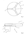
Fig. 1 eine Draufsicht eines Ausführungsbeispiels einer magnetischen Fangvorrichtung für Magnetrührstäbchen in Übereinstimmung mit der vorliegenden Erfindung veranschaulicht; -
Fig. 2 eine erste Schnittansicht der magnetischen Fangvorrichtung für Magnetrührstäbchen, die längs durch einen Abstandshalter verläuft, zeigt; -
Fig. 3 eine zweite Schnittansicht der magnetischen Fangvorrichtung für Magnetrührstäbchen, die quer durch den Abstandshalter verläuft, zeigt; und -
Fig. 4 eine Vorderansicht eines Abstandshalters zeigt; -
Fig. 5 eine Seitenansicht eines Abstandshalters zeigt; -
Fig. 6 eine schematische Schnittansicht der magnetischen Fangvorrichtung für Magnetrührstäbchen auf einem Ausguss eines Ausgussbeckens aufgesetzt zeigt; und -
Fig. 7 ein zweites Ausführungsbeispiel einer magnetischen Fangvorrichtung mit Abstandshaltern mit treppenartiger Abstufung zeigt. -
Fig. 1 veranschaulicht ein Ausführungsbeispiel einer magnetischen Fangvorrichtung 1 für Magnetrührstäbchen. Vor einer detaillierten Beschreibung der Ausführungsbeispiele, folgen zunächst allgemeine Erläuterungen zu den Ausführungsbeispielen. - Wie eingangs erwähnt, passiert es in der (Labor-)Praxis oftmals, dass ein Magnetrührstäbchen zusammen mit der Flüssigkeit, die es umgerührt hat, in den Ausguss geschüttet wird und damit verloren geht. Die Magnetrührstäbchen sind zwar einzeln nicht besonders teuer, der Preis liegt zwischen ungefähr 1 bis 2 Euro, allerdings summieren sich die Kosten im Laufe der Zeit für verlorengegangen Magnetrührstäbchen auf.
- Manche Magnetrührstäbchen, insbesondere sehr kleine (wenige Millimeter groß) mit sehr geringen Gewicht, bspw. um die 0,1g, können auch deutlich teurer sein, z.B. bis zu 20 Euro.
- Insbesondere in größeren Laboren oder an Universitäten, in denen viele (unerfahrene) Benutzer in Laboren arbeiten, können mehrere hundert Magnetrührstäbchen im Jahr verloren gehen, indem sie einfach in den Ausguss gegossen werden, sodass die Kosten durch verlorengegangen Magnetrührstäbchen sich durchaus in einem vierstelligen Bereich bewegen können.
- Der Erfinder hat nun erkannt, dass es durch eine einfache und kostengünstige Lösung möglich ist, ein Magnetrührstäbchen aufzufangen, bevor es in den Ausguss gelangt, indem es mittels einer magnetischen Fangvorrichtung, die über dem Ausguss angeordnet ist, magnetisch angezogen und magnetisch festgehalten wird.
- Dazu weist die Fangvorrichtung für Magnetrührstäbchen einen magnetischen Fangabschnitt auf, der dazu ausgelegt ist, ein Magnetfeld zu erzeugen. Außerdem weist die magnetische Fangvorrichtung wenigstens ein Abstandselement auf, das wenigstens teilweise unterhalb des magnetischen Fangabschnitts angeordnet ist. Das Abstandselement ist dazu ausgelegt, die magnetischen Fangvorrichtung bzw. den magnetischen Fangabschnitt in einem bestimmten Abstand zum Ausguss zu halten. Der Abstand zwischen Ausguss und magnetischem Fangabschnitt bzw. der magnetischen Fangvorrichtung bildet dabei einen Durchgang für Flüssigkeit, die in den Ausguss geschüttet werden soll, auf dem die Fangvorrichtung angeordnet ist.
- Wie weiter oben erwähnt, wird in der täglichen Laborpraxis manchmal eine Flüssigkeit aus einem Behälter zusammen mit einem darin befindlichen Magnetrührstäbchen in ein Ausgussbecken geschüttet.
- Bei der magnetischen Fangvorrichtung erstreckt sich daher das wenigstens eine Abstandselement derart von dem magnetischen Fangabschnitt weg, dass ein Raum unterhalb des magnetischen Fangabschnitts entsteht, durch den eine Flüssigkeit mit einem Magnetrührstäbchen fließen kann. Außerdem kann Flüssigkeit von außerhalb der Fangvorrichtung unterhalb des Fangabschnitts und dem wenigstens einen oder zwischen mehreren Abstandselementen hindurchfließen, sodass sie in den Ausguss gelangt, der unterhalb des Fangabschnitts angeordnet ist.
- Die Flüssigkeit mit dem aufzuhaltenden Magnetrührstäbchen fließt also von außerhalb der Fangvorrichtung an dem wenigstens einen Abstandselement vorbei und unter dem magnetischen Fangabschnitt durch den Raum hindurch in den Ausguss. Die Magnetfeldstärke (magnetische Feldstärke) des von dem magnetischen Fangabschnitt erzeugten Magnetfelds ist dazu ausgelegt, das Magnetrührstäbchen magnetisch gegen die Schwerkraft aus der in den Ausguss durch den Raum unterhalb des magnetischen Fangabschnitts fließenden Flüssigkeit heraus anzuziehen und magnetisch an der Unterseite des magnetischen Fangabschnitts festzuhalten.
- Bei manchen Ausführungsbeispielen ist die Magnetfeldstärke des von der magnetischen Fangvorrichtung bzw. von ihrem Fangabschnitt erzeugten Magnetfeldes an einen bestimmten Typ von Magnetrührstäbchen angepasst, während bei anderen Ausführungsbeispielen die Magnetfeldstärke so hoch ist, dass alle handelsüblichen Magnetrührstäbchen, die typischerweise ein Gewicht von unter einem Gramm, bspw. bis hinunter zu 0,1g, oder einigen wenigen Gramm, bspw. 1-2 Gramm, oder bis maximal 50 Gramm haben, angezogen und von dem magnetischen Fangabschnitt festgehalten werden können. Manche Magnetrührstäbchen können auch ein höheres Gewicht haben, bspw. 100 Gramm und bei manchen Ausführungsbeispielen können auch solche schweren Magnetrührstäbchen von dem Magnetfeld angezogen, hochgehoben und festgehalten werden. Generell ist die vorliegende Erfindung nicht auf das Gewicht und die Maße bestimmter Magnetrührstäbchen beschränkt. Die in der Beschreibung genannten Gewichtsangaben und Maßangaben dienen nur zur Veranschaulichung der vorliegenden Erfindung.
- Außerdem ist bei manchen Ausführungsbeispielen die magnetische Fangvorrichtung an bestimmte Magnetrührstäbchen mit bestimmten Außenmaßen und einem bestimmten Gewicht angepasst. Bei anderen Ausführungsbeispielen hingegen können typische Magnetrührstäbchen mit bspw. Zylinderform und mit einer Länge von 6 mm, einem Durchmesser von 3 mm und einem Gewicht von 1 Gramm bis hin zu einer Länge von 80 mm, einem Durchmesser von 10 mm und einem Gewicht von 50 Gramm eingefangen und festgehalten werden. Magnetrührstäbchen, die länger als 80 mm sind, fallen typischerweise nicht mehr durch den Ausguss.
- Bei manchen Ausführungsformen können insbesondere auch sehr kleine Magnetrührstäbchen, die nur eine Ausdehnung im Millemeterbereich und ein Gewicht von unter einem Gramm haben, von gem Magnetfeld hochgehoben und festgehalten werden.
- Bei den Ausführungsbeispielen können Magnetrührstäbchen stäbchenförmig, d.h. zylinderförmig sein; sie können aber auch eine andere Form haben, wie sie im Stand der Technik bekannt ist, wie bspw. zylindrisch mit Ring, dreieckig, eiförmig, tablettenförmig, kugelförmig, zylindrisch mit konisch verjüngenden Enden, hantelförmig, vierkantförmig, tandemartig, etc.
- Bei manchen Ausführungsbeispielen weist das wenigstens eine Abstandselement wenigstens einen Auflageabschnitt auf, der dazu ausgelegt ist, auf einen Ausgussabschnitt eines Ausgusses eines Ausgussbeckens aufgelegt zu werden und es weist einen Begrenzungsabschnitt auf, der dazu ausgelegt ist, in den Ausguss wenigstens teilweise hineinzuragen.
- Folglich ist bei manchen Ausführungsbeispielen der Abstand zwischen dem unteren Bereich des magnetischen Fangabschnitts und einem Ausgussbeckenboden auf dem der Auflageabschnitt aufliegt durch das Abstandselement festgelegt. Damit ist bei manchen Ausführungsbeispielen auch die benötigte Magnetfeldstärke zum Anziehen und Festhalten eines bestimmten Magnetrührstäbchens festgelegt, da dem Fachmann bekannt ist, wie sich das Magnetfeld mit zunehmenden Abstand vom magnetischen Fangabschnitt weg verhält und abnimmt.
- Ferner kann die magnetische Fangvorrichtung bei Ausführungsbeispielen mit wenigstens zwei gegenüberliegenden Begrenzungsabschnitten nicht verrutschen, wenn sie auf den Ausguss entsprechend aufgesetzt ist, da die Begrenzungsabschnitte der Abstandselement in den Ausguss hineinragen und an den Innenseiten bzw. Innenwänden des Ausgusses anstoßen und damit die eine Seitwärtsbewegung verhindern.
- Bei manchen Ausführungsbeispielen bilden der Auflageabschnitt des wenigstens einen Abstandselements und der Begrenzungsabschnitt einen im Wesentlichen senkrechten Winkel zueinander. Bei manchen Ausgussbecken bilden das Abflussrohr und der Ausgussabschnitt, d.h. der Rand des Abflussrohrs, ebenfalls einen im Wesentlichen rechten Winkel, sodass bei solchen Ausführungsbeispielen die magnetische Fangvorrichtung passgenau auf bzw. in den Ausguss gesetzt werden kann. Das heißt der Auflagereich liegt im Wesentlichen vollständig auf dem Ausgussabschnitt und eventuell noch auf dem Bereich des Ausgussbeckens, der den Ausgussabschnitt umgibt und der bzw. die Begrenzungsabschnitte stoßen gegen die Innenwand des Ausgusses, sodass der Begrenzungsabschnitt und der Auflageabschnitt den rechten Winkel zwischen Ausgussrohr und Ausgussabschnitt umschließen.
- Bei manchen Ausführungsbeispielen weist ein Abstandselement mehrere Auflageabschnitte und Begrenzungsabschnitte auf, die bspw. durch eine treppenartige Abstufung an dem Abstandselement gebildet werden.
- Damit der bzw. die Begrenzungsabschnitte auch an Ausgüsse bzw. Ausgussrohre unterschiedlichen Durchmessers anpassbar sind, ist bei manchen Ausführungsbeispielen das wenigstes eine Abstandselement auch in einer lateralen Richtung beweglich in dem magnetischen Fangabschnitt angeordnet. Die laterale Richtung ist dabei bspw. im Wesentlichen parallel zur Ausgussbeckenoberfläche, wenn die magnetische Fangvorrichtung aufgesetzt ist, oder bei manchen Ausführungsbeispielen parallel zur Längsrichtung des magnetischen Fangabschnitts.
- Bei manchen Ausführungsbeispielen sind wenigstens zwei Abstandselemente vorhanden, die derart lateral beweglich sind, dass der Abstand zwischen den Abstandselementen verändert werden kann. Dazu sind die Abstandselemente bspw. gegenüberliegend angeordnet.
- Zum Führen des Abstandselements bzw. der Abstandselemente weist bei manchen Ausführungsbeispielen das Abstandselement einen Führungsabschnitt auf, der in eine Führungsschiene eingreift, die in dem magnetischen Fangabschnitt angeordnet ist.
- Bei manchen Ausführungsbeispielen können die beweglichen Abstandselemente an vorgegebenen Positionen durch Rastelemente festgehalten werden, die bspw. in der Führungsschiene angeordnet sind. Bei anderen Ausführungsbeispielen ist bspw. die Beweglichkeit der Abstandselemente durch eine raue Oberfläche in der Führungsschiene und/oder am Führungsabschnitt herabgesetzt, sodass die Abstandselemente in einer bestimmten Position bleiben und nicht leicht verrutschen.
- Das Magnetfeld zum Einfangen von Magnetrührstäbchen wird bei manchen Ausführungsbeispielen von einem Permanentmagneten und/oder Elektromagneten erzeugt, der in einem Aufnahmebereich des magnetischen Fangabschnitts angeordnet ist und zum Aufnehmen des magnetfelderzeugenden Elements eingerichtet ist.
- Wie erwähnt, kommt die magnetische Fangvorrichtung insbesondere im Laborbetrieb zum Einsatz, wo die Flüssigkeiten teilweise stark ätzend sind. Dementsprechend weist bei manchen Ausführungsbeispielen die Oberfläche wenigstens teilweise, insbesondere in den Bereichen, die mit Flüssigkeit in Berührung kommen können, ein säurebeständiges Material auf.
- Bei manchen Ausführungsbeispielen weist das säurebeständige Material wenigstens eines der folgenden Materialien auf: Glas, Edelmetall, Edelstahl, Chrom, Aluminium, Titan, Blei, Zink, Polytetrafluorethylen, und Kunststoff mit polyhalogenierten Kohlenwasserstoffen, Granit, Gneis, Porphyr, etc.
- Bei manchen Ausführungsbeispielen ist die gesamte Fangvorrichtung aus einem säurebeständigen Material, bspw. aus einem der oben erwähnten, hergestellt.
- Zurückkommend zu
Fig. 1 ist dort schematisch eine magnetische Fangvorrichtung 1 in einer Draufsicht von unten dargestellt. Die magnetische Fangvorrichtung 1 hat einen scheibenförmigen und magnetischen Fangabschnitt 2. Der magnetische Fangabschnitt 2 hat in der Mitte eine Aufnahme 4, in der ein Permanentmagnet eingelassen ist. Von dem mittleren Bereich um die Aufnahme 4 herum erstrecken sich drei identische Abstandshalter 3 sternförmig von der Mitte des Fangabschnitts 2 weg nach außen. Die drei Abstandshalter 3 bilden dabei jeweils einen Winkel von 120° zueinander. - Die magnetische Fangvorrichtung 1 ist vollständig aus säurebeständigem Kunststoff hergestellt und damit einfach und kostengünstig bspw. im Spritzgießverfahren herzustellen.
- Wie auch aus den
Fig. 2 bis 5 ersichtlich ist, hat jeder der drei Abstandshalter 3 einen Auflageabschnitt 8 und einen Begrenzungsabschnitt 6, die einen rechten Winkel zueinander einnehmen. Außerdem hat jeder der drei Abstandshalter 3 an der Oberseite einen Führungsabschnitt 7, der seitlich herausragt und sich über die gesamte Länge des Abstandshalters 3 erstreckt. Der Abstandshalter 3 hat dadurch an der Oberseite eine T-förmiges Profil (s.Fig. 4 ). - Die Fangabschnitt 2 hat für jeden Abstandshalter 3 einen Schiene 5, in die jeweils ein Führungsabschnitt 7 eines Abstandshalters 3 eingreift. Die Schienen 5 erstrecken sich jeweils von der Mitte, d.h. der Aufnahme 4, des Fangabschnitts 2 mit einem Winkel von 120° zueinander nach außen. Die Abstandshalter 3 mit dem jeweiligen Führungsabschnitt 7 sind dabei insgesamt kürzer ausgebildet als die Schiene 5 und können folglich in der Schiene 5 hin- und hergeschoben werden. Um ein Herausfallen der Abstandshalter 3 am äußeren Rand der Schienen 5 zu verhindern, sind die Schienen 5 am jeweiligen äußeren und inneren Ende blockiert.
- Dadurch, dass die Abstandshalter 3 verschiebbar sind, können sie an unterschiedliche Durchmesser von Ausgussrohren angepasst werden und die Begrenzungsabschnitte 6 können jeweils soweit nach außen geschoben werden, bis sie an die Innenwände eines Ausgussrohres stoßen. Dadurch ist ein sicherer Halt der Fangvorrichtung 1 in einem Ausgussrohr gewährleistet.
- Die Funktionsweise der magnetischen Fangvorrichtung 1 wird nun beispielhaft unter Bezugnahme auf
Fig. 6 beschrieben. - In
Fig. 6 ist die magnetische Fangvorrichtung 1 auf einen Ausguss 11 eines Ausgussbeckenbodens 12 aufgesetzt gezeigt. Dabei sind die Abstandshalter 3 so eingestellt, dass die jeweiligen Begrenzungsabschnitte 6 gegen die die Innwand des Ausgusses 11 (bzw. des Ausgussrohres) stoßen. Außerdem liegen die jeweiligen Auflageabschnitte 8 der Abstandshalter 3 auf einem oberen Ausgussabschnittsbereich 14 des Ausgusses 11 und auf einem Teilbereich des Ausgussbeckenbodens 12 auf, der den Ausguss 11 umgibt. - Wird nun eine Flüssigkeit 10 mit einem Magnetrührstäbchen 13 in das Ausgussbecken geschüttet, so fließt die Flüssigkeit 10 zusammen mit dem Magnetrührstäbchen 13 auf dem Ausgussbeckenboden 12 entlang bis zum Ausguss 11. Das Magnetrührstäbchen 13 nimmt dabei verschiedenen Positionen ein, von denen zwei in
Fig. 6 als 13a und 13b gekennzeichnet sind. Die Flüssigkeit 10 fließt zusammen mit dem Magnetrührstäbchen auf die magnetische Fangvorrichtung 1 zu (Position 13a des Magnetrührstäbchens) und fließt unter dem magnetischen Fangabschnitt 2 und zwischen zwei Abstandshaltern 3 hindurch in den Raum 9 unterhalb des Fangabschnitts 2 (Position 13b des Magnetrührstäbchens). In dem Raum 9 wirkt die magnetische Anziehungskraft des Permanentmagneten in der Aufnahme 4 des Fangabschnitts 2 auf das Magnetrührstäbchen 13 und zieht das Magnetrührstäbchen 13 gegen die Schwerkraft an und hält es in dem Bereich der Aufnahme 4 an der Unterseite des Fangabschnitts 2 fest, während die Flüssigkeit 10 in den Ausguss 11 fließt. Das Magnetfeld des magnetischen Fangabschnitts trennt demnach im Raum 9 das Magnetrührstäbchen 13 von der Flüssigkeit 10, bevor diese in den Ausguss 11 gelangt. Damit wird sicher verhindert, dass das Magnetrührstäbchen 13 selbst durch die Flüssigkeit 10 in den Ausguss 11 gespült wird. - Der Abstand zwischen der Unterseite des magnetischen Fangabschnitts 2 und dem Ausguss 11 bzw. dem Ausgussbeckenboden 12 ist durch die Abstandshalter 3 definiert und erstreckt sich von der Unterseite des magnetischen Fangabschnitts 2 zu den Auflageabschnitten 8 der Abstandshalter 3.
- Das Magnetfeld, das von dem im Aufnahmebereich 4 angordneten Permanentmagneten erzeugt wird ist dabei so stark, dass es das Magnetrührstäbchen 13 gegen die Strömung der Flüssigkeit 10 und gegen die Schwerkraft anziehen kann und an der Unterseite des Fangabschnitts 2 festhalten kann.
- Im eben beschriebenen Ausführungsbeispiel sind die Abstandshalter 3 verschiebbar und dadurch an Ausgüsse unterschiedlichen Durchmessers anpassbar. Bei anderen Ausführungsbeispielen sind die Abstandshalter bspw: fest an dem Fangabschnitt 2 angebracht oder an diesem integral ausgebildet.
- Außerdem hat bei manchen Ausführungsbeispielen, wie beispielhaft in
Fig. 7 in einer Schnittansicht gezeigt, eine magnetische Fangvorrichtung 1', die ansonsten gleich zur Fangvorrichtung 1 des oben beschriebenen Ausführungsbeispiels ist, drei Abstandshalter 3' mit mehreren treppenartige Abstufungen, die jeweils einen Auflageabschnitt 8a-d und einen Begrenzungsabschnitt 6a-d bilden. - Dabei sind die treppenartigen Abstufungen derart ausgebildet, dass sich der Abstand gegenüberliegender Begrenzungsabschnitte 6a-d je nach Treppenstufe verändert. Außerdem verändert sich der Abstand zwischen der Unterseite des Fangabschnitts 2 und dem Auflageabschnitt 8a-d je nach Treppenstufe. Die treppenartige Abstufung ist derart ausgestaltet, dass der Abstand einander gegenüberliegender Begrenzungsflächen 6d am kleinsten ist, wenn der Abstand zwischen der Unterseite des Fangabschnitts 2 und dem zugehörigen Auflageabschnitt 8d am größten ist und umgekehrt. Das heißt der Abstand zwischen der Unterseite des Fangabschnitts 2 und dem Auflageabschnitt 8a auf der obersten Treppenstufe ist am kleinsten, wenn der Abstand zwischen gegenüberliegenden Begrenzungsabschnitten 6a am größten ist. Auf diese Art und Weise kann die magnetische Fangvorrichtung 1' passend auf Ausgüsse mit unterschiedlichen Durchmessern aufgesetzt werden. Allerdings ist bei diesem Ausführungsbeispiel der Abstand zwischen der Unterseite des Fangabschnitts 2 und dem Auflageabschnitt 8a-d, der auf dem Ausgussbeckenboden aufliegt, davon abhängig, auf welchem Auflageabschnitt 8a-d die Fangvorrichtung aufliegt.
- In den oben im Zusammenhang mit
Fig. 1 bis 7 beschrieben Ausführungsbeispielen hat das Magnetrührstäbchen 13 bspw. eine Länge von 10 mm und einen Durchmesser von 3 mm, sowie ein Gewicht von 1 Gramm. Wie oben bereits ausgeführt, können die Magnetrührstäbchen 13 auch andere Dimensionen und Gewicht haben und die vorliegende Erfindung ist nicht auf dieses Ausführungsbeispiel beschränkt. - Bei den beschriebenen Ausführungsbeispielen ist der magnetische Fangabschnitt 2 scheibenförmig ausgebildet, damit er einfach von einem Benutzer in die Hand genommen werden kann und das eingefangene Magnetrührstäbchen einfach entfernt werden kann.
- Bei anderen Ausführungsbeispielen hat der magnetische Fangabschnitt eine beliebige Form, wie bspw. rechteckig, dreieckig, sternförmig, oval, etc. Außerdem kann bei manchen Ausführungsbeispielen der magnetische Fangabschnitt 2 aus einem magnetischen Material hergestellt sein, sodass die Aufnahme 4 entfällt.
- Darüberhinaus ist die vorliegende Erfindung nicht auf eine bestimmte Anzahl oder Form von Abstandshaltern bzw. Abstandselemente eingeschränkt. Grundsätzlich erfüllt bei manchen Ausführungsbeispielen das oder die Abstandselemente die Funktion, einen Durchgang für eine Flüssigkeit mit einem Magnetrührstäbchen unterhalb des Fangabschnitts zu schaffen und ein Wegrutschen vom Ausguss zu verhindern.
Claims (11)
- Fangvorrichtung für Magnetrührstäbchen, umfassend:- einen magnetischen Fangabschnitt (2), der dazu ausgelegt ist, ein Magnetfeld zu erzeugen; und- wenigstens ein Abstandselement (3, 3'), das wenigstens teilweise unterhalb des Fangabschnitts (2) angeordnet ist;
dadurch gekennzeichnet, dass
sich das wenigstens eine Abstandselement (3, 3') derart von dem magnetischen Fangabschnitt (2) weg erstreckt, dass ein Raum (9) unterhalb des magnetischen Fangabschnitts (2) gebildet ist, durch den eine Flüssigkeit (10) samt einem oder mehreren Magnetrührstäbchen (13) hindurch fließen kann, und wobei der magnetische Fangabschnitt (2) einen Aufnahmebereich (4) zum Aufnehmen eines magnetfelderzeugenden Elements aufweist, dessen Magnetfeldstärke dazu ausgelegt ist, das oder die Magnetrührstäbchen (13) aus der Flüssigkeit (10) magnetisch gegen die Schwerkraft in Richtung des magnetischen Fangabschnitts (2) anzuziehen und magnetisch an dem magnetischen Fangabschnitt (2) festzuhalten. - Fangvorrichtung für Magnetrührstäbchen nach Anspruch 1, wobei das wenigstens eine Abstandselement (3, 3') einen Auflageabschnitt (8, 8a-d) aufweist, der dazu ausgelegt ist, auf einen Ausgussabschnitt (14) eines Ausgusses (11) eines Ausgussbeckens (12) aufgelegt zu werden, und einen Begrenzungsabschnitt (6, 6a-d), der dazu ausgelegt ist, in den Ausguss (11) wenigstens teilweise hineinzuragen.
- Fangvorrichtung für Magnetrührstäbchen nach Anspruch 2, bei welche das wenigstens eine Abstandselement (3') mehrere Auflageabschnitte (8a-d) und Begrenzungsabschnitte (6a-d) aufweist.
- Fangvorrichtung für Magnetrührstäbchen nach Anspruch 2 oder 3, wobei der Auflageabschnitt (8, 8a-d) und der Begrenzungsabschnitt (6, 6a-d) einen im Wesentlichen senkrechten Winkel zueinander bilden.
- Fangvorrichtung für Magnetrührstäbchen nach einem der vorhergehenden Ansprüche 2 bis 4, wobei das wenigstes eine Abstandselement (3) in einer lateralen Richtung beweglich in dem magnetischen Fangabschnitt (2) angeordnet ist.
- Fangvorrichtung für Magnetrührstäbchen nach Anspruch 5, wenigstens zwei Abstandselemente (3) aufweisen, die derart lateral beweglich sind, dass der Abstand zwischen den Abstandselementen (3) verändert werden kann.
- Fangvorrichtung für Magnetrührstäbchen nach einem der vorhergehenden Ansprüche 5 und 6, wobei das Abstandselement (3) einen Führungsabschnitt (7) aufweist, der in eine Führungsschiene (5) eingreift, die in dem Fangabschnitt (2) angeordnet ist.
- Fangvorrichtung für Magnetrührstäbchen nach Anspruch 1, wobei das magnetfelderzeugende Element ein Permanentmagnet und/oder ein Elektromagnet ist.
- Fangvorrichtung für Magnetrührstäbchen nach einem der vorhergehenden Ansprüche, wobei die Fangvorrichtung an der Oberfläche wenigstens teilweise ein säurebeständiges Material aufweist.
- Fangvorrichtung für Magnetrührstäbchen nach Anspruch 9, wobei das säurebeständige Material wenigstens eines der folgenden Materialien aufweist: Glas, Edelmetall, Edelstahl, Chrom, Aluminium, Titan, Blei, Zink, Polytetrafluorethylen, und Kunststoff mit polyhalogenierten Kohlenwasserstoffen, Granit, Gneis und Porphyr.
- Fangvorrichtung für Magnetrührstäbchen nach einem der vorhergehenden Ansprüche, wobei die Magnetfeldstärke des magnetfelderzeugenden Elements dazu ausgelegt ist, Magnetrührstäbchen mit einem Gewicht von bis zu 50 Gramm anzuziehen und an dem magnetischen Fangabschnitt (2) festzuhalten.
Applications Claiming Priority (1)
| Application Number | Priority Date | Filing Date | Title |
|---|---|---|---|
| DE102011012404A DE102011012404A1 (de) | 2011-02-25 | 2011-02-25 | Fangvorrichtung für Magnetrührstäbchen |
Publications (2)
| Publication Number | Publication Date |
|---|---|
| EP2492005A1 EP2492005A1 (de) | 2012-08-29 |
| EP2492005B1 true EP2492005B1 (de) | 2014-07-16 |
Family
ID=45811246
Family Applications (1)
| Application Number | Title | Priority Date | Filing Date |
|---|---|---|---|
| EP12001283.6A Not-in-force EP2492005B1 (de) | 2011-02-25 | 2012-02-27 | Fangvorrichtung für Magnetrührstäbchen |
Country Status (2)
| Country | Link |
|---|---|
| EP (1) | EP2492005B1 (de) |
| DE (1) | DE102011012404A1 (de) |
Citations (1)
| Publication number | Priority date | Publication date | Assignee | Title |
|---|---|---|---|---|
| EP2028322A2 (de) * | 2007-08-23 | 2009-02-25 | Bel-Art Products, Inc. | Magnetisches Sieb für Spülen |
Family Cites Families (4)
| Publication number | Priority date | Publication date | Assignee | Title |
|---|---|---|---|---|
| ATE153255T1 (de) * | 1992-07-20 | 1997-06-15 | Unilever Nv | Magnetisches ruhrsystem |
| JP3349248B2 (ja) * | 1994-03-22 | 2002-11-20 | 千寿製薬株式会社 | 流通型角膜透過実験器具およびこの実験器具を用いた実験装置 |
| EP1210158A4 (de) * | 1999-07-13 | 2003-02-12 | Hammonds Technical Serv Inc | Vorrichtung und verfahren zur chlorung |
| DE10025381A1 (de) * | 2000-05-24 | 2001-12-06 | Britta Kurzer | Vorrichtung und Verfahren zum Lösen eines Gases in einer Flüssigkeit, insbesondere Sauerstoff in Wasser |
-
2011
- 2011-02-25 DE DE102011012404A patent/DE102011012404A1/de not_active Withdrawn
-
2012
- 2012-02-27 EP EP12001283.6A patent/EP2492005B1/de not_active Not-in-force
Patent Citations (1)
| Publication number | Priority date | Publication date | Assignee | Title |
|---|---|---|---|---|
| EP2028322A2 (de) * | 2007-08-23 | 2009-02-25 | Bel-Art Products, Inc. | Magnetisches Sieb für Spülen |
Also Published As
| Publication number | Publication date |
|---|---|
| EP2492005A1 (de) | 2012-08-29 |
| DE102011012404A1 (de) | 2012-08-30 |
Similar Documents
| Publication | Publication Date | Title |
|---|---|---|
| DE60113515T2 (de) | Apparat zum Einsammeln oder Freisetzen magnetischer Partikel | |
| EP2015863B1 (de) | Behälteranordnung mit einem behälter mit flexibler wandung | |
| DE202017001238U1 (de) | Kunststoff-Magnetseparationsplatte zur Durchführung automatischer Magnetseparationsprozesse | |
| DE102016103064A1 (de) | Sanitärwannenanordnung | |
| DE10215283B4 (de) | Vorrichtung zur Aufnahme von Substraten | |
| EP3377190B1 (de) | Filterscheibe | |
| EP2492005B1 (de) | Fangvorrichtung für Magnetrührstäbchen | |
| CH464861A (de) | Rührteil für einen Magnetrührer | |
| DE102012002364B4 (de) | Vorrichtung zum Formen von Speiseeis | |
| DE102016106183B4 (de) | Ablaufgarnitur | |
| DE102016107219B4 (de) | Anordnung zum Verschließen einer Befüllöffnung im Boden eines Trinkgefäßes | |
| DE102016120053B3 (de) | Haltervorrichtung und Deckelvorrichtung für ein Gefäß, Gefäßsystem und Verfahren zum Zusammenbau des Gefäßsystems | |
| DE102017000894A1 (de) | Abflußstopfen für den Sanitärbereich mit Magnetausziehung | |
| DE102011005816B4 (de) | Dosiervorrichtung | |
| WO2003033124A1 (de) | Rührkörper | |
| DE202015006600U1 (de) | Vorrichtung zum Befüllen zumindest eines Behälters mit einem Medium | |
| EP3497202B1 (de) | Tankauslauf mit wirbelbrecher und montageverfahren für einen wirbelbrecher am tankauslauf eines tanks | |
| CH235632A (de) | Dichtungseinrichtung für unter hohem Druck stehende Gefässverschlüsse. | |
| DE102004056912B3 (de) | Probenahmegestell mit Rinne | |
| DE202009006376U1 (de) | Halter zur Aufnahme von Werbemitteln | |
| DE8633243U1 (de) | Schacht für Entwässerungsleitungen | |
| CH717025A2 (de) | Wannen- oder beckenartiges Behältnis, insbesondere Sanitärwanne, Sanitärbecken oder Spülenbecken. | |
| DE2738214C2 (de) | Dosiervorrichtung | |
| DE102006017393A1 (de) | Schöpflöffel | |
| WO2012041880A1 (de) | Vorrichtung zum behandeln von flüssigkeit |
Legal Events
| Date | Code | Title | Description |
|---|---|---|---|
| PUAI | Public reference made under article 153(3) epc to a published international application that has entered the european phase |
Free format text: ORIGINAL CODE: 0009012 |
|
| AK | Designated contracting states |
Kind code of ref document: A1 Designated state(s): AL AT BE BG CH CY CZ DE DK EE ES FI FR GB GR HR HU IE IS IT LI LT LU LV MC MK MT NL NO PL PT RO RS SE SI SK SM TR |
|
| AX | Request for extension of the european patent |
Extension state: BA ME |
|
| 17P | Request for examination filed |
Effective date: 20121204 |
|
| 17Q | First examination report despatched |
Effective date: 20130211 |
|
| GRAP | Despatch of communication of intention to grant a patent |
Free format text: ORIGINAL CODE: EPIDOSNIGR1 |
|
| INTG | Intention to grant announced |
Effective date: 20140207 |
|
| RIC1 | Information provided on ipc code assigned before grant |
Ipc: B01F 13/08 20060101AFI20140124BHEP Ipc: B01F 15/00 20060101ALN20140124BHEP Ipc: E03C 1/264 20060101ALI20140124BHEP |
|
| GRAS | Grant fee paid |
Free format text: ORIGINAL CODE: EPIDOSNIGR3 |
|
| GRAA | (expected) grant |
Free format text: ORIGINAL CODE: 0009210 |
|
| AK | Designated contracting states |
Kind code of ref document: B1 Designated state(s): AL AT BE BG CH CY CZ DE DK EE ES FI FR GB GR HR HU IE IS IT LI LT LU LV MC MK MT NL NO PL PT RO RS SE SI SK SM TR |
|
| REG | Reference to a national code |
Ref country code: GB Ref legal event code: FG4D Free format text: NOT ENGLISH |
|
| REG | Reference to a national code |
Ref country code: CH Ref legal event code: EP Ref country code: CH Ref legal event code: NV Representative=s name: E. BLUM AND CO. AG PATENT- UND MARKENANWAELTE , CH |
|
| REG | Reference to a national code |
Ref country code: IE Ref legal event code: FG4D Free format text: LANGUAGE OF EP DOCUMENT: GERMAN |
|
| REG | Reference to a national code |
Ref country code: AT Ref legal event code: REF Ref document number: 677238 Country of ref document: AT Kind code of ref document: T Effective date: 20140815 |
|
| REG | Reference to a national code |
Ref country code: DE Ref legal event code: R096 Ref document number: 502012000981 Country of ref document: DE Effective date: 20140828 |
|
| REG | Reference to a national code |
Ref country code: NL Ref legal event code: VDEP Effective date: 20140716 |
|
| REG | Reference to a national code |
Ref country code: LT Ref legal event code: MG4D |
|
| PG25 | Lapsed in a contracting state [announced via postgrant information from national office to epo] |
Ref country code: ES Free format text: LAPSE BECAUSE OF FAILURE TO SUBMIT A TRANSLATION OF THE DESCRIPTION OR TO PAY THE FEE WITHIN THE PRESCRIBED TIME-LIMIT Effective date: 20140716 Ref country code: PT Free format text: LAPSE BECAUSE OF FAILURE TO SUBMIT A TRANSLATION OF THE DESCRIPTION OR TO PAY THE FEE WITHIN THE PRESCRIBED TIME-LIMIT Effective date: 20141117 Ref country code: GR Free format text: LAPSE BECAUSE OF FAILURE TO SUBMIT A TRANSLATION OF THE DESCRIPTION OR TO PAY THE FEE WITHIN THE PRESCRIBED TIME-LIMIT Effective date: 20141017 Ref country code: NO Free format text: LAPSE BECAUSE OF FAILURE TO SUBMIT A TRANSLATION OF THE DESCRIPTION OR TO PAY THE FEE WITHIN THE PRESCRIBED TIME-LIMIT Effective date: 20141016 Ref country code: FI Free format text: LAPSE BECAUSE OF FAILURE TO SUBMIT A TRANSLATION OF THE DESCRIPTION OR TO PAY THE FEE WITHIN THE PRESCRIBED TIME-LIMIT Effective date: 20140716 Ref country code: SE Free format text: LAPSE BECAUSE OF FAILURE TO SUBMIT A TRANSLATION OF THE DESCRIPTION OR TO PAY THE FEE WITHIN THE PRESCRIBED TIME-LIMIT Effective date: 20140716 Ref country code: BG Free format text: LAPSE BECAUSE OF FAILURE TO SUBMIT A TRANSLATION OF THE DESCRIPTION OR TO PAY THE FEE WITHIN THE PRESCRIBED TIME-LIMIT Effective date: 20141016 Ref country code: LT Free format text: LAPSE BECAUSE OF FAILURE TO SUBMIT A TRANSLATION OF THE DESCRIPTION OR TO PAY THE FEE WITHIN THE PRESCRIBED TIME-LIMIT Effective date: 20140716 |
|
| PG25 | Lapsed in a contracting state [announced via postgrant information from national office to epo] |
Ref country code: IS Free format text: LAPSE BECAUSE OF FAILURE TO SUBMIT A TRANSLATION OF THE DESCRIPTION OR TO PAY THE FEE WITHIN THE PRESCRIBED TIME-LIMIT Effective date: 20141116 Ref country code: NL Free format text: LAPSE BECAUSE OF FAILURE TO SUBMIT A TRANSLATION OF THE DESCRIPTION OR TO PAY THE FEE WITHIN THE PRESCRIBED TIME-LIMIT Effective date: 20140716 Ref country code: CY Free format text: LAPSE BECAUSE OF FAILURE TO SUBMIT A TRANSLATION OF THE DESCRIPTION OR TO PAY THE FEE WITHIN THE PRESCRIBED TIME-LIMIT Effective date: 20140716 Ref country code: PL Free format text: LAPSE BECAUSE OF FAILURE TO SUBMIT A TRANSLATION OF THE DESCRIPTION OR TO PAY THE FEE WITHIN THE PRESCRIBED TIME-LIMIT Effective date: 20140716 Ref country code: RS Free format text: LAPSE BECAUSE OF FAILURE TO SUBMIT A TRANSLATION OF THE DESCRIPTION OR TO PAY THE FEE WITHIN THE PRESCRIBED TIME-LIMIT Effective date: 20140716 Ref country code: LV Free format text: LAPSE BECAUSE OF FAILURE TO SUBMIT A TRANSLATION OF THE DESCRIPTION OR TO PAY THE FEE WITHIN THE PRESCRIBED TIME-LIMIT Effective date: 20140716 |
|
| REG | Reference to a national code |
Ref country code: DE Ref legal event code: R097 Ref document number: 502012000981 Country of ref document: DE |
|
| PG25 | Lapsed in a contracting state [announced via postgrant information from national office to epo] |
Ref country code: DK Free format text: LAPSE BECAUSE OF FAILURE TO SUBMIT A TRANSLATION OF THE DESCRIPTION OR TO PAY THE FEE WITHIN THE PRESCRIBED TIME-LIMIT Effective date: 20140716 Ref country code: SK Free format text: LAPSE BECAUSE OF FAILURE TO SUBMIT A TRANSLATION OF THE DESCRIPTION OR TO PAY THE FEE WITHIN THE PRESCRIBED TIME-LIMIT Effective date: 20140716 Ref country code: EE Free format text: LAPSE BECAUSE OF FAILURE TO SUBMIT A TRANSLATION OF THE DESCRIPTION OR TO PAY THE FEE WITHIN THE PRESCRIBED TIME-LIMIT Effective date: 20140716 Ref country code: IT Free format text: LAPSE BECAUSE OF FAILURE TO SUBMIT A TRANSLATION OF THE DESCRIPTION OR TO PAY THE FEE WITHIN THE PRESCRIBED TIME-LIMIT Effective date: 20140716 Ref country code: RO Free format text: LAPSE BECAUSE OF FAILURE TO SUBMIT A TRANSLATION OF THE DESCRIPTION OR TO PAY THE FEE WITHIN THE PRESCRIBED TIME-LIMIT Effective date: 20140716 Ref country code: CZ Free format text: LAPSE BECAUSE OF FAILURE TO SUBMIT A TRANSLATION OF THE DESCRIPTION OR TO PAY THE FEE WITHIN THE PRESCRIBED TIME-LIMIT Effective date: 20140716 |
|
| PLBE | No opposition filed within time limit |
Free format text: ORIGINAL CODE: 0009261 |
|
| STAA | Information on the status of an ep patent application or granted ep patent |
Free format text: STATUS: NO OPPOSITION FILED WITHIN TIME LIMIT |
|
| 26N | No opposition filed |
Effective date: 20150417 |
|
| PG25 | Lapsed in a contracting state [announced via postgrant information from national office to epo] |
Ref country code: BE Free format text: LAPSE BECAUSE OF NON-PAYMENT OF DUE FEES Effective date: 20150228 |
|
| PG25 | Lapsed in a contracting state [announced via postgrant information from national office to epo] |
Ref country code: LU Free format text: LAPSE BECAUSE OF FAILURE TO SUBMIT A TRANSLATION OF THE DESCRIPTION OR TO PAY THE FEE WITHIN THE PRESCRIBED TIME-LIMIT Effective date: 20150227 |
|
| PG25 | Lapsed in a contracting state [announced via postgrant information from national office to epo] |
Ref country code: MC Free format text: LAPSE BECAUSE OF FAILURE TO SUBMIT A TRANSLATION OF THE DESCRIPTION OR TO PAY THE FEE WITHIN THE PRESCRIBED TIME-LIMIT Effective date: 20140716 |
|
| REG | Reference to a national code |
Ref country code: IE Ref legal event code: MM4A |
|
| REG | Reference to a national code |
Ref country code: FR Ref legal event code: ST Effective date: 20151030 |
|
| PG25 | Lapsed in a contracting state [announced via postgrant information from national office to epo] |
Ref country code: SI Free format text: LAPSE BECAUSE OF FAILURE TO SUBMIT A TRANSLATION OF THE DESCRIPTION OR TO PAY THE FEE WITHIN THE PRESCRIBED TIME-LIMIT Effective date: 20140716 |
|
| PG25 | Lapsed in a contracting state [announced via postgrant information from national office to epo] |
Ref country code: IE Free format text: LAPSE BECAUSE OF NON-PAYMENT OF DUE FEES Effective date: 20150227 |
|
| PG25 | Lapsed in a contracting state [announced via postgrant information from national office to epo] |
Ref country code: FR Free format text: LAPSE BECAUSE OF NON-PAYMENT OF DUE FEES Effective date: 20150302 |
|
| GBPC | Gb: european patent ceased through non-payment of renewal fee |
Effective date: 20160227 |
|
| PG25 | Lapsed in a contracting state [announced via postgrant information from national office to epo] |
Ref country code: MT Free format text: LAPSE BECAUSE OF FAILURE TO SUBMIT A TRANSLATION OF THE DESCRIPTION OR TO PAY THE FEE WITHIN THE PRESCRIBED TIME-LIMIT Effective date: 20140716 |
|
| PG25 | Lapsed in a contracting state [announced via postgrant information from national office to epo] |
Ref country code: GB Free format text: LAPSE BECAUSE OF NON-PAYMENT OF DUE FEES Effective date: 20160227 |
|
| PG25 | Lapsed in a contracting state [announced via postgrant information from national office to epo] |
Ref country code: HU Free format text: LAPSE BECAUSE OF FAILURE TO SUBMIT A TRANSLATION OF THE DESCRIPTION OR TO PAY THE FEE WITHIN THE PRESCRIBED TIME-LIMIT; INVALID AB INITIO Effective date: 20120227 Ref country code: SM Free format text: LAPSE BECAUSE OF FAILURE TO SUBMIT A TRANSLATION OF THE DESCRIPTION OR TO PAY THE FEE WITHIN THE PRESCRIBED TIME-LIMIT Effective date: 20140716 |
|
| PG25 | Lapsed in a contracting state [announced via postgrant information from national office to epo] |
Ref country code: HR Free format text: LAPSE BECAUSE OF FAILURE TO SUBMIT A TRANSLATION OF THE DESCRIPTION OR TO PAY THE FEE WITHIN THE PRESCRIBED TIME-LIMIT Effective date: 20140716 |
|
| PG25 | Lapsed in a contracting state [announced via postgrant information from national office to epo] |
Ref country code: TR Free format text: LAPSE BECAUSE OF FAILURE TO SUBMIT A TRANSLATION OF THE DESCRIPTION OR TO PAY THE FEE WITHIN THE PRESCRIBED TIME-LIMIT Effective date: 20140716 |
|
| REG | Reference to a national code |
Ref country code: AT Ref legal event code: MM01 Ref document number: 677238 Country of ref document: AT Kind code of ref document: T Effective date: 20170227 |
|
| PG25 | Lapsed in a contracting state [announced via postgrant information from national office to epo] |
Ref country code: AT Free format text: LAPSE BECAUSE OF NON-PAYMENT OF DUE FEES Effective date: 20170227 |
|
| PG25 | Lapsed in a contracting state [announced via postgrant information from national office to epo] |
Ref country code: MK Free format text: LAPSE BECAUSE OF FAILURE TO SUBMIT A TRANSLATION OF THE DESCRIPTION OR TO PAY THE FEE WITHIN THE PRESCRIBED TIME-LIMIT Effective date: 20140716 |
|
| PG25 | Lapsed in a contracting state [announced via postgrant information from national office to epo] |
Ref country code: AL Free format text: LAPSE BECAUSE OF FAILURE TO SUBMIT A TRANSLATION OF THE DESCRIPTION OR TO PAY THE FEE WITHIN THE PRESCRIBED TIME-LIMIT Effective date: 20140716 |
|
| PGFP | Annual fee paid to national office [announced via postgrant information from national office to epo] |
Ref country code: CH Payment date: 20210324 Year of fee payment: 10 |
|
| PGFP | Annual fee paid to national office [announced via postgrant information from national office to epo] |
Ref country code: DE Payment date: 20210323 Year of fee payment: 10 |
|
| REG | Reference to a national code |
Ref country code: DE Ref legal event code: R079 Ref document number: 502012000981 Country of ref document: DE Free format text: PREVIOUS MAIN CLASS: B01F0013080000 Ipc: B01F0033450000 |
|
| REG | Reference to a national code |
Ref country code: DE Ref legal event code: R119 Ref document number: 502012000981 Country of ref document: DE |
|
| REG | Reference to a national code |
Ref country code: CH Ref legal event code: PL |
|
| PG25 | Lapsed in a contracting state [announced via postgrant information from national office to epo] |
Ref country code: LI Free format text: LAPSE BECAUSE OF NON-PAYMENT OF DUE FEES Effective date: 20220228 Ref country code: DE Free format text: LAPSE BECAUSE OF NON-PAYMENT OF DUE FEES Effective date: 20220901 Ref country code: CH Free format text: LAPSE BECAUSE OF NON-PAYMENT OF DUE FEES Effective date: 20220228 |