EP2490786B1 - Filtereinrichtung - Google Patents
Filtereinrichtung Download PDFInfo
- Publication number
- EP2490786B1 EP2490786B1 EP10751625.4A EP10751625A EP2490786B1 EP 2490786 B1 EP2490786 B1 EP 2490786B1 EP 10751625 A EP10751625 A EP 10751625A EP 2490786 B1 EP2490786 B1 EP 2490786B1
- Authority
- EP
- European Patent Office
- Prior art keywords
- filter
- guide
- filter device
- ring
- pin
- Prior art date
- Legal status (The legal status is an assumption and is not a legal conclusion. Google has not performed a legal analysis and makes no representation as to the accuracy of the status listed.)
- Active
Links
Images


Classifications
-
- B—PERFORMING OPERATIONS; TRANSPORTING
- B01—PHYSICAL OR CHEMICAL PROCESSES OR APPARATUS IN GENERAL
- B01D—SEPARATION
- B01D29/00—Filters with filtering elements stationary during filtration, e.g. pressure or suction filters, not covered by groups B01D24/00 - B01D27/00; Filtering elements therefor
- B01D29/96—Filters with filtering elements stationary during filtration, e.g. pressure or suction filters, not covered by groups B01D24/00 - B01D27/00; Filtering elements therefor in which the filtering elements are moved between filtering operations; Particular measures for removing or replacing the filtering elements; Transport systems for filters
-
- B—PERFORMING OPERATIONS; TRANSPORTING
- B01—PHYSICAL OR CHEMICAL PROCESSES OR APPARATUS IN GENERAL
- B01D—SEPARATION
- B01D27/00—Cartridge filters of the throw-away type
- B01D27/08—Construction of the casing
-
- B—PERFORMING OPERATIONS; TRANSPORTING
- B01—PHYSICAL OR CHEMICAL PROCESSES OR APPARATUS IN GENERAL
- B01D—SEPARATION
- B01D29/00—Filters with filtering elements stationary during filtration, e.g. pressure or suction filters, not covered by groups B01D24/00 - B01D27/00; Filtering elements therefor
- B01D29/11—Filters with filtering elements stationary during filtration, e.g. pressure or suction filters, not covered by groups B01D24/00 - B01D27/00; Filtering elements therefor with bag, cage, hose, tube, sleeve or like filtering elements
- B01D29/13—Supported filter elements
- B01D29/15—Supported filter elements arranged for inward flow filtration
-
- B—PERFORMING OPERATIONS; TRANSPORTING
- B01—PHYSICAL OR CHEMICAL PROCESSES OR APPARATUS IN GENERAL
- B01D—SEPARATION
- B01D35/00—Filtering devices having features not specifically covered by groups B01D24/00 - B01D33/00, or for applications not specifically covered by groups B01D24/00 - B01D33/00; Auxiliary devices for filtration; Filter housing constructions
- B01D35/14—Safety devices specially adapted for filtration; Devices for indicating clogging
- B01D35/153—Anti-leakage or anti-return valves
-
- B—PERFORMING OPERATIONS; TRANSPORTING
- B01—PHYSICAL OR CHEMICAL PROCESSES OR APPARATUS IN GENERAL
- B01D—SEPARATION
- B01D35/00—Filtering devices having features not specifically covered by groups B01D24/00 - B01D33/00, or for applications not specifically covered by groups B01D24/00 - B01D33/00; Auxiliary devices for filtration; Filter housing constructions
- B01D35/16—Cleaning-out devices, e.g. for removing the cake from the filter casing or for evacuating the last remnants of liquid
-
- B—PERFORMING OPERATIONS; TRANSPORTING
- B01—PHYSICAL OR CHEMICAL PROCESSES OR APPARATUS IN GENERAL
- B01D—SEPARATION
- B01D35/00—Filtering devices having features not specifically covered by groups B01D24/00 - B01D33/00, or for applications not specifically covered by groups B01D24/00 - B01D33/00; Auxiliary devices for filtration; Filter housing constructions
- B01D35/30—Filter housing constructions
- B01D35/306—Filter mounting adapter
-
- B—PERFORMING OPERATIONS; TRANSPORTING
- B01—PHYSICAL OR CHEMICAL PROCESSES OR APPARATUS IN GENERAL
- B01D—SEPARATION
- B01D2201/00—Details relating to filtering apparatus
- B01D2201/29—Filter cartridge constructions
- B01D2201/291—End caps
-
- B—PERFORMING OPERATIONS; TRANSPORTING
- B01—PHYSICAL OR CHEMICAL PROCESSES OR APPARATUS IN GENERAL
- B01D—SEPARATION
- B01D2201/00—Details relating to filtering apparatus
- B01D2201/29—Filter cartridge constructions
- B01D2201/291—End caps
- B01D2201/295—End caps with projections extending in a radial outward direction, e.g. for use as a guide, spacing means
-
- B—PERFORMING OPERATIONS; TRANSPORTING
- B01—PHYSICAL OR CHEMICAL PROCESSES OR APPARATUS IN GENERAL
- B01D—SEPARATION
- B01D2201/00—Details relating to filtering apparatus
- B01D2201/40—Special measures for connecting different parts of the filter
- B01D2201/4007—Use of cam or ramp systems
-
- B—PERFORMING OPERATIONS; TRANSPORTING
- B01—PHYSICAL OR CHEMICAL PROCESSES OR APPARATUS IN GENERAL
- B01D—SEPARATION
- B01D2201/00—Details relating to filtering apparatus
- B01D2201/40—Special measures for connecting different parts of the filter
- B01D2201/4046—Means for avoiding false mounting of different parts
- B01D2201/4053—Means for avoiding false mounting of different parts using keys
-
- B—PERFORMING OPERATIONS; TRANSPORTING
- B01—PHYSICAL OR CHEMICAL PROCESSES OR APPARATUS IN GENERAL
- B01D—SEPARATION
- B01D2201/00—Details relating to filtering apparatus
- B01D2201/52—Filter identification means
Definitions
- the present invention relates to a filter device, in particular an oil or fuel filter, with a filter housing having a filter housing and a filter housing housing according to the preamble of claim 1.
- a filter insert for a liquid filter with two end disks which has a closure pin (pin) which closes a discharge channel for emptying the filter when changing the filter cartridge when the filter cartridge is inserted.
- a filter device with a filter housing for receiving a filter element wherein the filter element has an axially and eccentrically protruding pin (pin), the is inserted in the inserted state in a formed in the filter housing pin receptacle.
- pin axially and eccentrically protruding pin
- the present invention therefore deals with the problem of providing a filter device of the generic type, an improved or at least one alternative embodiment, which is structurally simple on the one hand and on the other hand facilitates mounting of the filter device.
- the present invention is based on the general idea of providing a tubular dome on the filter housing pot which serves as a guide for a ring filter element to be inserted into the filter housing pot in a filter device known per se with a filter housing having a filter housing pot and a filter housing cover.
- the ring filter element to be used has an axially projecting pin on a lower end disk, by means of which, when the filter device is mounted, it engages at least partially in a channel in the housing of the filter housing cup and seals it tightly.
- the inventively provided on the filter housing pot tubular dome engages mounted filter device in an interior of the ring filter element.
- this tubular dome has a guide contour which interacts with a guide element arranged on the ring filter element so that it is guided along the guide contour during assembly, thereby enabling a simple and precise insertion of the pin into the channel of the filter housing tube.
- the provision of the guide contour on the tubular dome of the filter housing pot not only offers a structurally extremely simple way to guide the ring filter element, but it can thereby be dispensed in particular to other, often elaborately designed, guide contours.
- the guide contour Despite the structurally relatively simple embodiment of the guide contour, this causes during assembly of the filter device an accurate and targeted guiding of the ring filter element, which can be guided in the direction of the filter housing tube side channel and also introduced into this when sliding along the ringfilterelement remedyen pins along the guide contour.
- the guide element is designed as a radially inwardly directed guide pin.
- the dome-side guide contour has an axial groove, to which the guide element is guided during assembly of the filter device, and which is arranged relative to the ringfilterelement kiten pin such that it is inserted into the filter housing cup side channel, if the guide element in the Axial groove enters.
- This precise alignment of the pin relative to the guide element and the interaction of the guide element with the domide guide contour causes only authorized ring filter elements can be used in the filter device, but not other ring filter elements, for example, have no pin.
- the filter housing pot-side channel is not closed and allows the ring filter element bypass flow bypassing, which greatly reduces the filtering effect of the filter device.
- both the guide element and a distance between this and the pin must correspond exactly predefined dimensions, so that when the guide element interacts with the dome-shaped guide contour, the pin also enters the filter housing tube-side channel, provided that the guide element is in the Axialnut the guide contour is pushed.
- the use of unauthorized ring filter elements is thus at least severely hampered, as a result of which damage to an internal combustion engine connected to the filter device can be reduced or eliminated altogether.
- the guide contour is formed on the cathedral in the manner of a circular ramp, wherein the axial groove between the highest and the lowest point of the ramp is arranged.
- This insertion or sliding process can be generated, for example, by means of a Aufschraubvorgangs the filter housing cover on the filter housing pot.
- the guide contour is formed on the dome in the manner of a chamfered cannula, wherein at the lowest point, the axial groove is arranged.
- a particularly smooth feeding of the guide element to the axial groove and thus a particularly smooth feeding of the pin to the filter housing pot side channel can also be achieved.
- the pin according to the invention no longer has such a similar property and therefore can, for example, from an elastic material, in particular made of rubber.
- the tubular dome on the filter housing pot can, for example, form part of a clean channel.
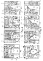
- a filter device 1, for example.
- An oil or fuel filter, or air filter for a motor vehicle, a from a filter housing pot 2 and a filter housing lid 3 screwed it filter housing 4 formed.
- a per se known ring filter element 5 is arranged, which is supported with respect to an interior 6, for example.
- the ring filter element 5 is also limited in a known manner by an upper end plate 8 and a lower end plate 9 in the axial direction.
- a pin 10 In the axial direction of the lower end plate 9 projecting while a pin 10 is provided (see, for example, the 6 and 7 ), which preferably tightly engages with a completely mounted filter device 1 in a filter housing cup side channel 11 and thereby closes it.
- a sealing element formed in a known manner for example an O-ring seal 12, can be provided on the pin 10.
- Channel 11 is in most cases an idle channel.
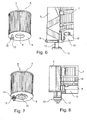
- a tubular dome 13 On the filter housing pot 2 is also a tubular dome 13 (see. FIGS. 2 and 3 ) is provided, which engages with mounted filter device 1 in the interior 6 of the ring filter element 5 and, for example, forms a part of a clean channel.
- a guide contour 14 is now provided at a free end of this tubular dome 13, which is provided with a guide element 15 arranged on the ring filter element 5 (cf., for example, FIG. 4 and 5 ) cooperates.
- This guide contour 14 may, for example, in the manner of a circular ramp be trained as in the Fig. 3 is shown, or in the manner of a beveled cannula, which, for example, according to the Fig. 2 is shown.
- Both guide contours 14 is common that they have an axial groove 16, to which the guide member 15 is guided during assembly of the filter device 1 and which is aligned relative to the pin 10 so that it can be inserted into the filter housing cup side channel 11, provided the guide element 15 enters or is pushed into the axial groove 16.
- FIG. 4a to 4d An assembly of the filter device 1 is in various steps according to the Fig. 4a to 4d shown.
- the ring filter element 5 is inserted in the mounting step 4a in the filter housing pot 2 and indeed so far until it rests with the guide member 15 on the dome-side guide contour 14.
- the ring filter element 5 for example.
- the guide member 15, as shown in the Fig. 4b is shown, along the guide contour 14 along slides and indeed to the axial groove 16, which is preferably arranged between the highest and the lowest point of the ramp-like guide contour 14.
- the pin 10 After reaching the axial groove 16, the pin 10 is coaxially aligned with the channel 11, so that the ring filter element 5 can be inserted in the axial direction with the guide member 15 in the axial groove 16 and simultaneously with the pin 10 in the channel 11.
- This condition is, for example, according to Fig. 4d shown.
- the axial groove 16 is preferably located at the lowest point of the guide contour 14. It is irrelevant in this case whether the guide element 15, such as in accordance with the Fig. 4a to 4d is shown on the inner frame 7, or as in the Fig. 5a to 5d is shown, is arranged on the lower end plate 9. In both cases, in this case the guide element 15 is designed as a radially inwardly directed guide pin.
- the lower end plate 9 is sealed with respect to the dome 13 via a sealing lip 17 which rests tightly against an outer surface of the tubular dome 13 when the ring filter element 5 is installed.
- This sealing lip 17 is flexible and preferably formed integrally with the lower end plate 9.
- the sealing lip 17 has built-in ring filter element 5 upwards, as for example.
- a separate sealing ring 18 is provided which rests tightly against the outer surface of the tubular dome 13 with built-ring filter element 5.
- Such a sealing ring 18 is, for example, in the Fig. 5 . 7 . 11 . 14 . 15a and 16c shown.
- the pin 10 slides along the ramp and is thus formed as a sliding element, but rather elastically, for example. Can be made of rubber, since the pin 10 must no longer have any sliding properties.
- the pin 10 may be simply tubular and carries an O-ring seal 12 on a head.
- the pin 10 can of course also have a cross-sectional cross-sectional structure, as for example, according to the FIGS. 7 and 8 recognizable, causing the pin 10 in total gets stiffer.
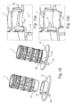
- the ring filter element 5 can generally be designed as a pleated star with a papery or flow-shaped filter material.
- Fig. 9 is a ring filter element 5 and in detail whose lower end plate 9 is shown, which also has a merely tubular pin 10, at the free end of an O-ring seal 12 is still arranged.
- Fig. 10 has the lower end plate 9 of the ring filter element 5 according to the Fig. 9 an upwardly facing sealing lip 17.
- the complete lower end plate 9 made of a single material, for example. Made of plastic or rubber, is produced, in particular injected, so that the sealing lip 17 is formed only on the lower end plate 9.
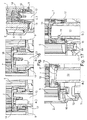
- Fig. 11a and 11b different seals 18,19 are shown, wherein the seal according to the Fig. 11a , similar to that according to the Fig. 15b , For example, is formed only as a sealing coating 19 on a radially inwardly facing annular web 20.
- the sealing ring 18, as this according to the Fig. 11b . 14 and 15a is shown formed as a separate component, for example. Of silicone or a non-woven.
- Fig. 12 According to the Fig. 12 are shown an exploded view and a mounting position of the inner frame 7 with the associated lower end plate 9, which in the case of Fig. 13a an upwardly directed sealing lip 17 and in the case of Fig. 13b may have a downwardly directed sealing lip 17.
- the guide element 15 is arranged on the inner frame 7, which at the same time has a further guide element 15 'which cooperates with a guide contour 14' arranged on the lower end plate 9.
- the guide element 15 according to the FIGS. 14 and 15 arranged on the lower end plate 9.
- Fig. 16a, b and c again the individual sealing variants are shown, so that according to the Fig. 16a an upwardly pointing and abutting the dome 13 sealing lip 17 is shown, while the lower end plate 9 according to the Fig. 16b has a downwardly directed sealing lip 17.
- Fig. 16c a further variant of the guide contour 14 is shown, in which case an additional sealing ring 18 is arranged on the lower end plate 9.
- Figs. 17a and 17b is again illustrated how the sealing lip 17 in the embodiment of the Fig. 16a , applies to the outer surface of the dome 13, provided that the ring filter element 5 has reached its Endcoolwinkel ein and can be moved axially downwards in this.
- a condition for this axial displacement of the ring filter element 5 via the dome 13 is that the annular filter element-side guide member 15 is located in the axial groove 16, which means that the pin 10 can be coaxially aligned with the filter housing cup side channel 11 and inserted therein. This is, for example, according to the Figs. 17a and 17b shown.
- a further filter device 1 is shown with a check valve 21 and a bypass valve 22.
- the dome 13 which in turn is also centrally located, a guide contour 14 at its free end, which cooperates with a filter element-side guide element 15, not shown .
- a not-shown pin 10 is disposed on the ring filter element 5 and at the lower end plate 9, which in fully assembled filter device 1 in a filter housing side channel 11 (see. Fig. 19 ) engages and thereby closes tightly.
- the filter device 1 can be achieved decisive advantages in terms of the operation and the installation of the same: Firstly, a use of unauthorized ring filter elements, which, for example, would also lead to damage to an internal combustion engine can be reliably prevented because these both the ring filter element side guide element 15, as well as the dom-side guide contour 14 and the exactly aligned with the guide element 15 pin 10 would have to be installed correctly in the filter device 1 can. If, for example, a ring filter element without a pin 10 is used, then the channel 11, in particular the idling channel, is not sealed tightly and a bypass flow occurring immediately bypasses the ring filter element.
- the assembly and in particular the changing of the ring filter element 5 according to the invention can be significantly simplified, as by means of the guide member 15 and the guide contour 14 is given a forced guidance, the forcibly positioned the ring filter element 5 when screwing the filter housing cover 3 so that the pin 10 in alignment with the channel 11 aligned and thus can be easily introduced into this.
- Another advantage is that in the present filter device 1, the pin 10 no longer has sliding properties and for this reason, for example, much more flexible, in particular rubber, can be formed.
Landscapes
- Chemical & Material Sciences (AREA)
- Chemical Kinetics & Catalysis (AREA)
- Lubrication Details And Ventilation Of Internal Combustion Engines (AREA)
- Filtration Of Liquid (AREA)
- Sampling And Sample Adjustment (AREA)
- Filtering Of Dispersed Particles In Gases (AREA)
Priority Applications (1)
| Application Number | Priority Date | Filing Date | Title |
|---|---|---|---|
| PL10751625T PL2490786T3 (pl) | 2009-10-20 | 2010-08-31 | Urządzenie filtracyjne |
Applications Claiming Priority (2)
| Application Number | Priority Date | Filing Date | Title |
|---|---|---|---|
| DE102009049868A DE102009049868A1 (de) | 2009-10-20 | 2009-10-20 | Filtereinrichtung |
| PCT/EP2010/062684 WO2011047913A1 (de) | 2009-10-20 | 2010-08-31 | Filtereinrichtung |
Publications (2)
| Publication Number | Publication Date |
|---|---|
| EP2490786A1 EP2490786A1 (de) | 2012-08-29 |
| EP2490786B1 true EP2490786B1 (de) | 2015-03-18 |
Family
ID=42938388
Family Applications (1)
| Application Number | Title | Priority Date | Filing Date |
|---|---|---|---|
| EP10751625.4A Active EP2490786B1 (de) | 2009-10-20 | 2010-08-31 | Filtereinrichtung |
Country Status (10)
| Country | Link |
|---|---|
| US (1) | US9205355B2 (pl) |
| EP (1) | EP2490786B1 (pl) |
| JP (1) | JP5603427B2 (pl) |
| CN (1) | CN102648036B (pl) |
| BR (1) | BR112012009230B1 (pl) |
| DE (1) | DE102009049868A1 (pl) |
| ES (1) | ES2537825T3 (pl) |
| PL (1) | PL2490786T3 (pl) |
| RU (1) | RU2543199C2 (pl) |
| WO (1) | WO2011047913A1 (pl) |
Cited By (6)
| Publication number | Priority date | Publication date | Assignee | Title |
|---|---|---|---|---|
| DE102016209919A1 (de) | 2016-06-06 | 2017-12-07 | Mahle International Gmbh | Filtereinrichtung |
| DE102016224159A1 (de) * | 2016-12-05 | 2018-06-07 | Mahle International Gmbh | Ringfilterelement |
| DE102016124587A1 (de) * | 2016-12-16 | 2018-06-21 | Hengst Se | Positioniervorrichtung mit einem Positionierführungselement für eine Positionierung eines ersten Bauteils relativ zu einem damit zu verbindenden zweiten Bauteil in deren Umfangsrichtung |
| US10428776B2 (en) | 2014-06-05 | 2019-10-01 | Donaldson Company, Inc. | Fluid filter cartridge, fluid filter arrangement, and method for servicing a fluid filter arrangement |
| DE102018218632A1 (de) | 2018-10-31 | 2020-04-30 | Mahle International Gmbh | Filtereinrichtung |
| DE102021003162B3 (de) | 2021-06-18 | 2022-09-22 | Mahle International Gmbh | Filtersystem, Positioniermittel, Filterelement und Verfahren zum Einsetzen und Positionieren eines Filterelements |
Families Citing this family (39)
| Publication number | Priority date | Publication date | Assignee | Title |
|---|---|---|---|---|
| DE102009041523B4 (de) | 2009-09-15 | 2024-01-25 | Mahle International Gmbh | Filtereinrichtung |
| DE102009054523A1 (de) * | 2009-12-10 | 2011-06-16 | Hengst Gmbh & Co. Kg | Flüssigkeitsfilter |
| DE102011077798A1 (de) | 2011-06-20 | 2012-12-20 | Hengst Gmbh & Co. Kg | Flüssigkeitsfilter mit einem exzentrischen Flüssigkeitsablasskanal |
| DE102011088742A1 (de) * | 2011-12-15 | 2013-06-20 | Mahle International Gmbh | Filtereinrichtung |
| DE102012007762A1 (de) * | 2012-04-20 | 2013-10-24 | Mann + Hummel Gmbh | Ölfilter einer Brennkraftmaschine und Ölfilterelement eines Ölfilters |
| US20150129479A1 (en) * | 2012-04-26 | 2015-05-14 | International Engine Intellectual Property Company Llc | Rotational filter assembly with orientation structure |
| DE102013202449A1 (de) * | 2013-02-14 | 2014-08-14 | Mahle International Gmbh | Filtereinrichtung |
| CN105228717B (zh) * | 2013-03-22 | 2017-02-01 | 卡特彼勒公司 | 过滤组件 |
| DE102013205523A1 (de) * | 2013-03-27 | 2014-10-02 | Mahle International Gmbh | Filtereinrichtung |
| ITTO20130325A1 (it) * | 2013-04-23 | 2014-10-24 | N D R S R L Soc Unipersonale | Cartuccia per il filtraggio di liquidi |
| DE102014201680A1 (de) | 2014-01-30 | 2015-07-30 | Mahle International Gmbh | Filtereinrichtung |
| DE102015008693A1 (de) * | 2014-07-15 | 2016-01-21 | Mann + Hummel Gmbh | Hohlfilterelement eines Filters für Fluid, Filter und Filtergehäuse |
| KR101583713B1 (ko) * | 2014-11-13 | 2016-01-08 | 말레동현필터시스템 주식회사 | 회전형 드레인핀을 구비하는 오일필터모듈 |
| US11534774B2 (en) * | 2015-03-10 | 2022-12-27 | Arthrex, Inc. | Cellular component concentrator and filter apparatus and method of use thereof |
| DE102015207231B4 (de) * | 2015-04-21 | 2017-09-14 | Mahle International Gmbh | Filtereinrichtung |
| DE112016003243T5 (de) | 2015-08-31 | 2018-05-09 | Cummins Filtration Ip, Inc. | Filteranschlussdichtung |
| DE102015218184A1 (de) * | 2015-09-22 | 2017-03-23 | Mahle International Gmbh | Filtereinrichtung |
| DE102016203764A1 (de) | 2016-03-08 | 2017-09-14 | Mahle International Gmbh | Filtereinrichtung |
| US11045754B2 (en) * | 2016-09-14 | 2021-06-29 | Donaldson Company, Inc. | Liquid filter assembly |
| DE102016013388A1 (de) * | 2016-11-11 | 2018-05-17 | Mann+Hummel Gmbh | Filtersystem und Filterelement |
| US11383185B2 (en) | 2017-03-20 | 2022-07-12 | Cummins Filtration Ip, Inc. | Filter assembly with an inner filter element with a top rib |
| US11504659B2 (en) | 2017-07-13 | 2022-11-22 | Cummins Filtration Ip, Inc. | Endplate with guide feature |
| DE102017214718A1 (de) | 2017-08-23 | 2019-02-28 | Mahle International Gmbh | Filtereinrichtung |
| WO2020014141A1 (en) | 2018-07-10 | 2020-01-16 | Cummins Filtration Ip, Inc. | Alignment notch for an endcap of a filter element |
| EP3608009A1 (en) | 2018-08-10 | 2020-02-12 | Mann+Hummel GmbH | Filter system and filter element with improved positioning means |
| US20200114288A1 (en) * | 2018-10-10 | 2020-04-16 | Schroeder Industries, Llc | Filter assembly with authenticating filter element coupling and replaceable drop-in twist locking filter element therefor |
| DE102018009187A1 (de) | 2018-11-23 | 2020-05-28 | Hydac Filtertechnik Gmbh | Filtervorrichtung |
| DE102018221256A1 (de) * | 2018-12-07 | 2020-06-10 | Mahle International Gmbh | Filterelement für eine Filtereinrichtung |
| DE102018221262A1 (de) * | 2018-12-07 | 2020-06-10 | Mahle International Gmbh | Filterelement für eine Filtereinrichtung |
| DE102018221768A1 (de) * | 2018-12-14 | 2020-06-18 | Mahle International Gmbh | Filtereinrichtung |
| USD967330S1 (en) | 2019-03-21 | 2022-10-18 | Mahle International Gmbh | Pin for a filter element |
| US11452956B2 (en) | 2019-06-27 | 2022-09-27 | Mahle International Gmbh | Fuel filter |
| US11992788B2 (en) | 2019-06-27 | 2024-05-28 | Mahle International Gmbh | Filter device |
| EP3756748A1 (en) * | 2019-06-27 | 2020-12-30 | Mann+Hummel GmbH | Filter system having a primary and a secondary filter element and secondary filter element for such a filter system |
| US11426687B2 (en) | 2019-06-27 | 2022-08-30 | Mahle International Gmbh | Fuel filter |
| US11511217B2 (en) | 2020-09-22 | 2022-11-29 | Mahle International Gmbh | Filter and method of fabricating same |
| USD958288S1 (en) | 2020-10-09 | 2022-07-19 | Mahle International Gmbh | Filter device |
| FR3129848B1 (fr) | 2021-12-08 | 2023-10-27 | Sogefi Filtration Spa | Cartouche filtrante à bouchon décentré et Filtre pour liquide de moteur à combustion incluant la cartouche |
| CN119491532B (zh) * | 2025-01-16 | 2025-04-08 | 山西恒清源供水设备有限公司 | 一种带过滤净化功能的不锈钢水箱 |
Citations (1)
| Publication number | Priority date | Publication date | Assignee | Title |
|---|---|---|---|---|
| DE10353424A1 (de) * | 2003-11-15 | 2005-06-23 | Mahle Filtersysteme Gmbh | Flüssigkeitsfilter, insbesondere Ölfilter für ein Kraftfahrzeug |
Family Cites Families (25)
| Publication number | Priority date | Publication date | Assignee | Title |
|---|---|---|---|---|
| DE3903675A1 (de) * | 1989-02-08 | 1990-08-09 | Knecht Filterwerke Gmbh | Oelfilter zum reinigen von schmieroel |
| JP3039147B2 (ja) | 1992-06-29 | 2000-05-08 | いすゞ自動車株式会社 | 2−4ストローク切換エンジン |
| JP2561739Y2 (ja) * | 1992-07-17 | 1998-02-04 | 積水化学工業株式会社 | 管継手 |
| DE4330840C1 (de) * | 1993-09-11 | 1995-02-16 | Hengst Walter Gmbh & Co Kg | Filter für die Reinigung von Flüssigkeiten |
| JP2966366B2 (ja) * | 1997-02-19 | 1999-10-25 | 株式会社大洋プラスチックス工業所 | 格納式キャスタ装置 |
| JPH1133313A (ja) * | 1997-07-22 | 1999-02-09 | Denso Corp | オイルフィルタ及びそのエレメント並びにそのハウジング |
| US6488842B2 (en) * | 1999-02-26 | 2002-12-03 | Tadayoshi Nagaoka | Filtering device |
| JP2000343546A (ja) * | 1999-06-07 | 2000-12-12 | Sony Corp | 複合非球面レンズ作成方法及び複合非球面レンズ |
| JP3461144B2 (ja) * | 1999-07-19 | 2003-10-27 | Tdk株式会社 | クリーンボックス内ウエハ固定装置 |
| DE19951085A1 (de) * | 1999-10-23 | 2001-04-26 | Mahle Filtersysteme Gmbh | Flüssigkeitsfilter, insbesondere Ölfilter |
| JP4441068B2 (ja) * | 2000-06-20 | 2010-03-31 | 輝夫 松山 | 異径パイプの接続装置 |
| US6572768B1 (en) * | 2002-03-25 | 2003-06-03 | Arvin Technologies, Inc. | Oil filter apparatus |
| DE10246151A1 (de) * | 2002-10-01 | 2004-04-15 | Mahle Filtersysteme Gmbh | Ringfilterelement für ein Flüssigkeitsfilter |
| ITRE20030033A1 (it) * | 2003-03-31 | 2004-10-01 | Ufi Filters Spa | "basamento per cartuccia filtrante per motori a combustione interna" |
| RU2351387C2 (ru) * | 2003-05-19 | 2009-04-10 | Вабко Гмбх Энд Ко. Охг | Картридж для осушителя воздуха |
| US7060184B2 (en) * | 2003-05-21 | 2006-06-13 | Arvin Technologies, Inc. | Quick-drain valve member for use with filter apparatus |
| DE202005002955U1 (de) * | 2005-02-23 | 2006-07-06 | Hengst Gmbh & Co.Kg | Filtereinsatz für einen Flüssigkeitsfilter, insbesondere Ölfilter |
| FR2884728B1 (fr) * | 2005-04-20 | 2007-07-13 | Filtrauto Sa | Filtre a huile a vidange automatique |
| FR2885534B1 (fr) | 2005-05-13 | 2007-07-27 | Filtrauto Sa | Cartouche filtrante et systeme de montage d'une telle cartouche |
| DE102006028148A1 (de) * | 2006-06-16 | 2007-12-20 | Mahle International Gmbh | Kraftstofffilter |
| DE102006034482A1 (de) * | 2006-07-21 | 2008-01-24 | Joma-Polytec Kunststofftechnik Gmbh | Ölfilteranordnung und Filterelement hierfür |
| KR20080082694A (ko) | 2007-03-09 | 2008-09-12 | 주식회사 세원 | 오일 여과기 내의 드레인 밸브 구조 |
| DE102007062102A1 (de) * | 2007-12-21 | 2009-06-25 | Mahle International Gmbh | Filtereinrichtung |
| DE102008049007B4 (de) * | 2008-09-25 | 2019-08-08 | Mahle International Gmbh | Flüssigkeitsfilter |
| DE102009054523A1 (de) * | 2009-12-10 | 2011-06-16 | Hengst Gmbh & Co. Kg | Flüssigkeitsfilter |
-
2009
- 2009-10-20 DE DE102009049868A patent/DE102009049868A1/de not_active Ceased
-
2010
- 2010-08-31 RU RU2012113100/05A patent/RU2543199C2/ru active
- 2010-08-31 JP JP2012534600A patent/JP5603427B2/ja active Active
- 2010-08-31 ES ES10751625.4T patent/ES2537825T3/es active Active
- 2010-08-31 BR BR112012009230-8A patent/BR112012009230B1/pt active IP Right Grant
- 2010-08-31 EP EP10751625.4A patent/EP2490786B1/de active Active
- 2010-08-31 CN CN201080047657.3A patent/CN102648036B/zh active Active
- 2010-08-31 US US13/502,951 patent/US9205355B2/en active Active
- 2010-08-31 PL PL10751625T patent/PL2490786T3/pl unknown
- 2010-08-31 WO PCT/EP2010/062684 patent/WO2011047913A1/de not_active Ceased
Patent Citations (1)
| Publication number | Priority date | Publication date | Assignee | Title |
|---|---|---|---|---|
| DE10353424A1 (de) * | 2003-11-15 | 2005-06-23 | Mahle Filtersysteme Gmbh | Flüssigkeitsfilter, insbesondere Ölfilter für ein Kraftfahrzeug |
Cited By (7)
| Publication number | Priority date | Publication date | Assignee | Title |
|---|---|---|---|---|
| US10428776B2 (en) | 2014-06-05 | 2019-10-01 | Donaldson Company, Inc. | Fluid filter cartridge, fluid filter arrangement, and method for servicing a fluid filter arrangement |
| DE102016209919A1 (de) | 2016-06-06 | 2017-12-07 | Mahle International Gmbh | Filtereinrichtung |
| WO2017211541A1 (de) | 2016-06-06 | 2017-12-14 | Mahle International Gmbh | Filtereinrichtung |
| DE102016224159A1 (de) * | 2016-12-05 | 2018-06-07 | Mahle International Gmbh | Ringfilterelement |
| DE102016124587A1 (de) * | 2016-12-16 | 2018-06-21 | Hengst Se | Positioniervorrichtung mit einem Positionierführungselement für eine Positionierung eines ersten Bauteils relativ zu einem damit zu verbindenden zweiten Bauteil in deren Umfangsrichtung |
| DE102018218632A1 (de) | 2018-10-31 | 2020-04-30 | Mahle International Gmbh | Filtereinrichtung |
| DE102021003162B3 (de) | 2021-06-18 | 2022-09-22 | Mahle International Gmbh | Filtersystem, Positioniermittel, Filterelement und Verfahren zum Einsetzen und Positionieren eines Filterelements |
Also Published As
| Publication number | Publication date |
|---|---|
| ES2537825T3 (es) | 2015-06-12 |
| RU2012113100A (ru) | 2013-11-27 |
| RU2543199C2 (ru) | 2015-02-27 |
| US9205355B2 (en) | 2015-12-08 |
| CN102648036A (zh) | 2012-08-22 |
| JP2013508135A (ja) | 2013-03-07 |
| EP2490786A1 (de) | 2012-08-29 |
| BR112012009230A2 (pt) | 2016-08-23 |
| JP5603427B2 (ja) | 2014-10-08 |
| DE102009049868A1 (de) | 2011-04-21 |
| PL2490786T3 (pl) | 2015-08-31 |
| BR112012009230B1 (pt) | 2019-07-02 |
| CN102648036B (zh) | 2014-09-24 |
| US20120261326A1 (en) | 2012-10-18 |
| WO2011047913A1 (de) | 2011-04-28 |
Similar Documents
| Publication | Publication Date | Title |
|---|---|---|
| EP2490786B1 (de) | Filtereinrichtung | |
| EP1229985B1 (de) | Flüssigkeitsfilter, insbesondere ölfilter | |
| DE102009048412B3 (de) | Filtersystem und Filterelement zur Filtrierung von Fluiden | |
| EP1974786B1 (de) | Flüssigkeitsfilter | |
| EP3268106B1 (de) | Filter mit einem filterumgehungsventil und filtereinsatz dafür | |
| EP2604321B1 (de) | Filtereinrichtung | |
| DE102009041523A1 (de) | Filtereinrichtung | |
| DE102013008986B4 (de) | Filtereinrichtung, insbesondere Flüssigkeitsfilter | |
| WO2009080457A2 (de) | Flüssigkeitsfilter, insbesondere ölfilter | |
| DE102008049006A1 (de) | Flüssigkeitsfilter | |
| EP3498359B1 (de) | Filterelement und zugehörige filtereinrichtung | |
| DE102015008873B4 (de) | Filtereinrichtung mit einem hohlzylindrischen Filtermediumkörperund Abstützdom für eine Filtereinrichtung | |
| DE202011104691U1 (de) | Flüssigkeitsfilter, insbesondere ein Ölfilter | |
| EP3037150B1 (de) | Filtereinrichtung | |
| EP2314364B1 (de) | Filtereinrichtung | |
| WO2017198408A1 (de) | Filtereinrichtung | |
| DE102009048588A1 (de) | Filtereinrichtung, insbesondere zur Flüssigkeitsfilterung in Brennkraftmaschinen | |
| EP2783738B1 (de) | Filtereinrichtung | |
| DE102015222425A1 (de) | Spin-On Wechselfilter | |
| EP3099394A1 (de) | Filtereinrichtung mit leerlauf im deckel | |
| DE102016224159A1 (de) | Ringfilterelement | |
| DE102019206631A1 (de) | Flüssigfiltereinrichtung | |
| DE102021203253B3 (de) | Flüssigkeitsfiltereinrichtung | |
| EP2803399B1 (de) | Flüssigkeitsfilter | |
| EP2608864B1 (de) | Filter und verfahren zum herstellen desselben |
Legal Events
| Date | Code | Title | Description |
|---|---|---|---|
| PUAI | Public reference made under article 153(3) epc to a published international application that has entered the european phase |
Free format text: ORIGINAL CODE: 0009012 |
|
| 17P | Request for examination filed |
Effective date: 20120326 |
|
| AK | Designated contracting states |
Kind code of ref document: A1 Designated state(s): AL AT BE BG CH CY CZ DE DK EE ES FI FR GB GR HR HU IE IS IT LI LT LU LV MC MK MT NL NO PL PT RO SE SI SK SM TR |
|
| DAX | Request for extension of the european patent (deleted) | ||
| 17Q | First examination report despatched |
Effective date: 20130725 |
|
| GRAP | Despatch of communication of intention to grant a patent |
Free format text: ORIGINAL CODE: EPIDOSNIGR1 |
|
| INTG | Intention to grant announced |
Effective date: 20141126 |
|
| GRAS | Grant fee paid |
Free format text: ORIGINAL CODE: EPIDOSNIGR3 |
|
| GRAA | (expected) grant |
Free format text: ORIGINAL CODE: 0009210 |
|
| AK | Designated contracting states |
Kind code of ref document: B1 Designated state(s): AL AT BE BG CH CY CZ DE DK EE ES FI FR GB GR HR HU IE IS IT LI LT LU LV MC MK MT NL NO PL PT RO SE SI SK SM TR |
|
| REG | Reference to a national code |
Ref country code: GB Ref legal event code: FG4D Free format text: NOT ENGLISH |
|
| REG | Reference to a national code |
Ref country code: CH Ref legal event code: EP |
|
| REG | Reference to a national code |
Ref country code: IE Ref legal event code: FG4D Free format text: LANGUAGE OF EP DOCUMENT: GERMAN |
|
| REG | Reference to a national code |
Ref country code: AT Ref legal event code: REF Ref document number: 716170 Country of ref document: AT Kind code of ref document: T Effective date: 20150415 |
|
| REG | Reference to a national code |
Ref country code: DE Ref legal event code: R096 Ref document number: 502010009169 Country of ref document: DE Effective date: 20150430 |
|
| REG | Reference to a national code |
Ref country code: RO Ref legal event code: EPE |
|
| REG | Reference to a national code |
Ref country code: NL Ref legal event code: T3 |
|
| REG | Reference to a national code |
Ref country code: ES Ref legal event code: FG2A Ref document number: 2537825 Country of ref document: ES Kind code of ref document: T3 Effective date: 20150612 |
|
| PG25 | Lapsed in a contracting state [announced via postgrant information from national office to epo] |
Ref country code: HR Free format text: LAPSE BECAUSE OF FAILURE TO SUBMIT A TRANSLATION OF THE DESCRIPTION OR TO PAY THE FEE WITHIN THE PRESCRIBED TIME-LIMIT Effective date: 20150318 Ref country code: LT Free format text: LAPSE BECAUSE OF FAILURE TO SUBMIT A TRANSLATION OF THE DESCRIPTION OR TO PAY THE FEE WITHIN THE PRESCRIBED TIME-LIMIT Effective date: 20150318 Ref country code: NO Free format text: LAPSE BECAUSE OF FAILURE TO SUBMIT A TRANSLATION OF THE DESCRIPTION OR TO PAY THE FEE WITHIN THE PRESCRIBED TIME-LIMIT Effective date: 20150618 Ref country code: FI Free format text: LAPSE BECAUSE OF FAILURE TO SUBMIT A TRANSLATION OF THE DESCRIPTION OR TO PAY THE FEE WITHIN THE PRESCRIBED TIME-LIMIT Effective date: 20150318 Ref country code: SE Free format text: LAPSE BECAUSE OF FAILURE TO SUBMIT A TRANSLATION OF THE DESCRIPTION OR TO PAY THE FEE WITHIN THE PRESCRIBED TIME-LIMIT Effective date: 20150318 |
|
| REG | Reference to a national code |
Ref country code: LT Ref legal event code: MG4D |
|
| PG25 | Lapsed in a contracting state [announced via postgrant information from national office to epo] |
Ref country code: LV Free format text: LAPSE BECAUSE OF FAILURE TO SUBMIT A TRANSLATION OF THE DESCRIPTION OR TO PAY THE FEE WITHIN THE PRESCRIBED TIME-LIMIT Effective date: 20150318 Ref country code: GR Free format text: LAPSE BECAUSE OF FAILURE TO SUBMIT A TRANSLATION OF THE DESCRIPTION OR TO PAY THE FEE WITHIN THE PRESCRIBED TIME-LIMIT Effective date: 20150619 |
|
| REG | Reference to a national code |
Ref country code: PL Ref legal event code: T3 |
|
| PG25 | Lapsed in a contracting state [announced via postgrant information from national office to epo] |
Ref country code: EE Free format text: LAPSE BECAUSE OF FAILURE TO SUBMIT A TRANSLATION OF THE DESCRIPTION OR TO PAY THE FEE WITHIN THE PRESCRIBED TIME-LIMIT Effective date: 20150318 Ref country code: SK Free format text: LAPSE BECAUSE OF FAILURE TO SUBMIT A TRANSLATION OF THE DESCRIPTION OR TO PAY THE FEE WITHIN THE PRESCRIBED TIME-LIMIT Effective date: 20150318 Ref country code: PT Free format text: LAPSE BECAUSE OF FAILURE TO SUBMIT A TRANSLATION OF THE DESCRIPTION OR TO PAY THE FEE WITHIN THE PRESCRIBED TIME-LIMIT Effective date: 20150720 |
|
| PG25 | Lapsed in a contracting state [announced via postgrant information from national office to epo] |
Ref country code: IS Free format text: LAPSE BECAUSE OF FAILURE TO SUBMIT A TRANSLATION OF THE DESCRIPTION OR TO PAY THE FEE WITHIN THE PRESCRIBED TIME-LIMIT Effective date: 20150718 |
|
| REG | Reference to a national code |
Ref country code: DE Ref legal event code: R097 Ref document number: 502010009169 Country of ref document: DE |
|
| PLBE | No opposition filed within time limit |
Free format text: ORIGINAL CODE: 0009261 |
|
| STAA | Information on the status of an ep patent application or granted ep patent |
Free format text: STATUS: NO OPPOSITION FILED WITHIN TIME LIMIT |
|
| PG25 | Lapsed in a contracting state [announced via postgrant information from national office to epo] |
Ref country code: DK Free format text: LAPSE BECAUSE OF FAILURE TO SUBMIT A TRANSLATION OF THE DESCRIPTION OR TO PAY THE FEE WITHIN THE PRESCRIBED TIME-LIMIT Effective date: 20150318 |
|
| 26N | No opposition filed |
Effective date: 20151221 |
|
| PG25 | Lapsed in a contracting state [announced via postgrant information from national office to epo] |
Ref country code: SI Free format text: LAPSE BECAUSE OF FAILURE TO SUBMIT A TRANSLATION OF THE DESCRIPTION OR TO PAY THE FEE WITHIN THE PRESCRIBED TIME-LIMIT Effective date: 20150318 |
|
| PG25 | Lapsed in a contracting state [announced via postgrant information from national office to epo] |
Ref country code: MC Free format text: LAPSE BECAUSE OF FAILURE TO SUBMIT A TRANSLATION OF THE DESCRIPTION OR TO PAY THE FEE WITHIN THE PRESCRIBED TIME-LIMIT Effective date: 20150318 Ref country code: LU Free format text: LAPSE BECAUSE OF FAILURE TO SUBMIT A TRANSLATION OF THE DESCRIPTION OR TO PAY THE FEE WITHIN THE PRESCRIBED TIME-LIMIT Effective date: 20150831 |
|
| REG | Reference to a national code |
Ref country code: CH Ref legal event code: PL |
|
| PG25 | Lapsed in a contracting state [announced via postgrant information from national office to epo] |
Ref country code: LI Free format text: LAPSE BECAUSE OF NON-PAYMENT OF DUE FEES Effective date: 20150831 Ref country code: CH Free format text: LAPSE BECAUSE OF NON-PAYMENT OF DUE FEES Effective date: 20150831 |
|
| REG | Reference to a national code |
Ref country code: IE Ref legal event code: MM4A |
|
| PG25 | Lapsed in a contracting state [announced via postgrant information from national office to epo] |
Ref country code: IE Free format text: LAPSE BECAUSE OF NON-PAYMENT OF DUE FEES Effective date: 20150831 |
|
| REG | Reference to a national code |
Ref country code: FR Ref legal event code: PLFP Year of fee payment: 7 |
|
| PG25 | Lapsed in a contracting state [announced via postgrant information from national office to epo] |
Ref country code: MT Free format text: LAPSE BECAUSE OF FAILURE TO SUBMIT A TRANSLATION OF THE DESCRIPTION OR TO PAY THE FEE WITHIN THE PRESCRIBED TIME-LIMIT Effective date: 20150318 |
|
| PG25 | Lapsed in a contracting state [announced via postgrant information from national office to epo] |
Ref country code: SM Free format text: LAPSE BECAUSE OF FAILURE TO SUBMIT A TRANSLATION OF THE DESCRIPTION OR TO PAY THE FEE WITHIN THE PRESCRIBED TIME-LIMIT Effective date: 20150318 Ref country code: HU Free format text: LAPSE BECAUSE OF FAILURE TO SUBMIT A TRANSLATION OF THE DESCRIPTION OR TO PAY THE FEE WITHIN THE PRESCRIBED TIME-LIMIT; INVALID AB INITIO Effective date: 20100831 |
|
| PG25 | Lapsed in a contracting state [announced via postgrant information from national office to epo] |
Ref country code: CY Free format text: LAPSE BECAUSE OF FAILURE TO SUBMIT A TRANSLATION OF THE DESCRIPTION OR TO PAY THE FEE WITHIN THE PRESCRIBED TIME-LIMIT Effective date: 20150318 |
|
| REG | Reference to a national code |
Ref country code: FR Ref legal event code: PLFP Year of fee payment: 8 |
|
| PG25 | Lapsed in a contracting state [announced via postgrant information from national office to epo] |
Ref country code: MK Free format text: LAPSE BECAUSE OF FAILURE TO SUBMIT A TRANSLATION OF THE DESCRIPTION OR TO PAY THE FEE WITHIN THE PRESCRIBED TIME-LIMIT Effective date: 20150318 |
|
| REG | Reference to a national code |
Ref country code: FR Ref legal event code: PLFP Year of fee payment: 9 |
|
| PG25 | Lapsed in a contracting state [announced via postgrant information from national office to epo] |
Ref country code: AL Free format text: LAPSE BECAUSE OF FAILURE TO SUBMIT A TRANSLATION OF THE DESCRIPTION OR TO PAY THE FEE WITHIN THE PRESCRIBED TIME-LIMIT Effective date: 20150318 |
|
| P01 | Opt-out of the competence of the unified patent court (upc) registered |
Effective date: 20240527 |
|
| PGFP | Annual fee paid to national office [announced via postgrant information from national office to epo] |
Ref country code: NL Payment date: 20250821 Year of fee payment: 16 |
|
| PGFP | Annual fee paid to national office [announced via postgrant information from national office to epo] |
Ref country code: ES Payment date: 20250925 Year of fee payment: 16 |
|
| PGFP | Annual fee paid to national office [announced via postgrant information from national office to epo] |
Ref country code: DE Payment date: 20250820 Year of fee payment: 16 |
|
| PGFP | Annual fee paid to national office [announced via postgrant information from national office to epo] |
Ref country code: PL Payment date: 20250724 Year of fee payment: 16 Ref country code: IT Payment date: 20250825 Year of fee payment: 16 Ref country code: TR Payment date: 20250825 Year of fee payment: 16 |
|
| PGFP | Annual fee paid to national office [announced via postgrant information from national office to epo] |
Ref country code: BG Payment date: 20250822 Year of fee payment: 16 Ref country code: BE Payment date: 20250820 Year of fee payment: 16 Ref country code: GB Payment date: 20250821 Year of fee payment: 16 |
|
| PGFP | Annual fee paid to national office [announced via postgrant information from national office to epo] |
Ref country code: FR Payment date: 20250829 Year of fee payment: 16 Ref country code: AT Payment date: 20250821 Year of fee payment: 16 |
|
| PGFP | Annual fee paid to national office [announced via postgrant information from national office to epo] |
Ref country code: CZ Payment date: 20250827 Year of fee payment: 16 |
|
| PGFP | Annual fee paid to national office [announced via postgrant information from national office to epo] |
Ref country code: RO Payment date: 20250825 Year of fee payment: 16 |