EP2489754B1 - Hohles Stahlbohrgestänge und Herstellungsverfahren dafür - Google Patents
Hohles Stahlbohrgestänge und Herstellungsverfahren dafür Download PDFInfo
- Publication number
- EP2489754B1 EP2489754B1 EP12001073.1A EP12001073A EP2489754B1 EP 2489754 B1 EP2489754 B1 EP 2489754B1 EP 12001073 A EP12001073 A EP 12001073A EP 2489754 B1 EP2489754 B1 EP 2489754B1
- Authority
- EP
- European Patent Office
- Prior art keywords
- percent
- thread
- hardness
- less
- amount
- Prior art date
- Legal status (The legal status is an assumption and is not a legal conclusion. Google has not performed a legal analysis and makes no representation as to the accuracy of the status listed.)
- Active
Links
Images


Classifications
-
- C—CHEMISTRY; METALLURGY
- C22—METALLURGY; FERROUS OR NON-FERROUS ALLOYS; TREATMENT OF ALLOYS OR NON-FERROUS METALS
- C22C—ALLOYS
- C22C38/00—Ferrous alloys, e.g. steel alloys
- C22C38/18—Ferrous alloys, e.g. steel alloys containing chromium
- C22C38/40—Ferrous alloys, e.g. steel alloys containing chromium with nickel
- C22C38/42—Ferrous alloys, e.g. steel alloys containing chromium with nickel with copper
-
- C—CHEMISTRY; METALLURGY
- C21—METALLURGY OF IRON
- C21D—MODIFYING THE PHYSICAL STRUCTURE OF FERROUS METALS; GENERAL DEVICES FOR HEAT TREATMENT OF FERROUS OR NON-FERROUS METALS OR ALLOYS; MAKING METAL MALLEABLE, e.g. BY DECARBURISATION OR TEMPERING
- C21D1/00—General methods or devices for heat treatment, e.g. annealing, hardening, quenching or tempering
- C21D1/18—Hardening; Quenching with or without subsequent tempering
-
- C—CHEMISTRY; METALLURGY
- C21—METALLURGY OF IRON
- C21D—MODIFYING THE PHYSICAL STRUCTURE OF FERROUS METALS; GENERAL DEVICES FOR HEAT TREATMENT OF FERROUS OR NON-FERROUS METALS OR ALLOYS; MAKING METAL MALLEABLE, e.g. BY DECARBURISATION OR TEMPERING
- C21D9/00—Heat treatment, e.g. annealing, hardening, quenching or tempering, adapted for particular articles; Furnaces therefor
- C21D9/08—Heat treatment, e.g. annealing, hardening, quenching or tempering, adapted for particular articles; Furnaces therefor for tubular bodies or pipes
-
- C—CHEMISTRY; METALLURGY
- C21—METALLURGY OF IRON
- C21D—MODIFYING THE PHYSICAL STRUCTURE OF FERROUS METALS; GENERAL DEVICES FOR HEAT TREATMENT OF FERROUS OR NON-FERROUS METALS OR ALLOYS; MAKING METAL MALLEABLE, e.g. BY DECARBURISATION OR TEMPERING
- C21D9/00—Heat treatment, e.g. annealing, hardening, quenching or tempering, adapted for particular articles; Furnaces therefor
- C21D9/50—Heat treatment, e.g. annealing, hardening, quenching or tempering, adapted for particular articles; Furnaces therefor for welded joints
-
- C—CHEMISTRY; METALLURGY
- C22—METALLURGY; FERROUS OR NON-FERROUS ALLOYS; TREATMENT OF ALLOYS OR NON-FERROUS METALS
- C22C—ALLOYS
- C22C38/00—Ferrous alloys, e.g. steel alloys
- C22C38/001—Ferrous alloys, e.g. steel alloys containing N
-
- C—CHEMISTRY; METALLURGY
- C22—METALLURGY; FERROUS OR NON-FERROUS ALLOYS; TREATMENT OF ALLOYS OR NON-FERROUS METALS
- C22C—ALLOYS
- C22C38/00—Ferrous alloys, e.g. steel alloys
- C22C38/02—Ferrous alloys, e.g. steel alloys containing silicon
-
- C—CHEMISTRY; METALLURGY
- C22—METALLURGY; FERROUS OR NON-FERROUS ALLOYS; TREATMENT OF ALLOYS OR NON-FERROUS METALS
- C22C—ALLOYS
- C22C38/00—Ferrous alloys, e.g. steel alloys
- C22C38/04—Ferrous alloys, e.g. steel alloys containing manganese
-
- C—CHEMISTRY; METALLURGY
- C22—METALLURGY; FERROUS OR NON-FERROUS ALLOYS; TREATMENT OF ALLOYS OR NON-FERROUS METALS
- C22C—ALLOYS
- C22C38/00—Ferrous alloys, e.g. steel alloys
- C22C38/06—Ferrous alloys, e.g. steel alloys containing aluminium
-
- C—CHEMISTRY; METALLURGY
- C22—METALLURGY; FERROUS OR NON-FERROUS ALLOYS; TREATMENT OF ALLOYS OR NON-FERROUS METALS
- C22C—ALLOYS
- C22C38/00—Ferrous alloys, e.g. steel alloys
- C22C38/18—Ferrous alloys, e.g. steel alloys containing chromium
- C22C38/40—Ferrous alloys, e.g. steel alloys containing chromium with nickel
- C22C38/44—Ferrous alloys, e.g. steel alloys containing chromium with nickel with molybdenum or tungsten
-
- C—CHEMISTRY; METALLURGY
- C22—METALLURGY; FERROUS OR NON-FERROUS ALLOYS; TREATMENT OF ALLOYS OR NON-FERROUS METALS
- C22C—ALLOYS
- C22C38/00—Ferrous alloys, e.g. steel alloys
- C22C38/18—Ferrous alloys, e.g. steel alloys containing chromium
- C22C38/40—Ferrous alloys, e.g. steel alloys containing chromium with nickel
- C22C38/50—Ferrous alloys, e.g. steel alloys containing chromium with nickel with titanium or zirconium
-
- C—CHEMISTRY; METALLURGY
- C22—METALLURGY; FERROUS OR NON-FERROUS ALLOYS; TREATMENT OF ALLOYS OR NON-FERROUS METALS
- C22C—ALLOYS
- C22C38/00—Ferrous alloys, e.g. steel alloys
- C22C38/18—Ferrous alloys, e.g. steel alloys containing chromium
- C22C38/40—Ferrous alloys, e.g. steel alloys containing chromium with nickel
- C22C38/54—Ferrous alloys, e.g. steel alloys containing chromium with nickel with boron
-
- E—FIXED CONSTRUCTIONS
- E21—EARTH OR ROCK DRILLING; MINING
- E21B—EARTH OR ROCK DRILLING; OBTAINING OIL, GAS, WATER, SOLUBLE OR MELTABLE MATERIALS OR A SLURRY OF MINERALS FROM WELLS
- E21B17/00—Drilling rods or pipes; Flexible drill strings; Kellies; Drill collars; Sucker rods; Cables; Casings; Tubings
-
- E—FIXED CONSTRUCTIONS
- E21—EARTH OR ROCK DRILLING; MINING
- E21B—EARTH OR ROCK DRILLING; OBTAINING OIL, GAS, WATER, SOLUBLE OR MELTABLE MATERIALS OR A SLURRY OF MINERALS FROM WELLS
- E21B17/00—Drilling rods or pipes; Flexible drill strings; Kellies; Drill collars; Sucker rods; Cables; Casings; Tubings
- E21B17/02—Couplings; joints
- E21B17/04—Couplings; joints between rod or the like and bit or between rod and rod or the like
- E21B17/042—Threaded
- E21B17/0426—Threaded with a threaded cylindrical portion, e.g. for percussion rods
-
- C—CHEMISTRY; METALLURGY
- C21—METALLURGY OF IRON
- C21D—MODIFYING THE PHYSICAL STRUCTURE OF FERROUS METALS; GENERAL DEVICES FOR HEAT TREATMENT OF FERROUS OR NON-FERROUS METALS OR ALLOYS; MAKING METAL MALLEABLE, e.g. BY DECARBURISATION OR TEMPERING
- C21D1/00—General methods or devices for heat treatment, e.g. annealing, hardening, quenching or tempering
- C21D1/34—Methods of heating
- C21D1/42—Induction heating
-
- C—CHEMISTRY; METALLURGY
- C21—METALLURGY OF IRON
- C21D—MODIFYING THE PHYSICAL STRUCTURE OF FERROUS METALS; GENERAL DEVICES FOR HEAT TREATMENT OF FERROUS OR NON-FERROUS METALS OR ALLOYS; MAKING METAL MALLEABLE, e.g. BY DECARBURISATION OR TEMPERING
- C21D2221/00—Treating localised areas of an article
-
- Y—GENERAL TAGGING OF NEW TECHNOLOGICAL DEVELOPMENTS; GENERAL TAGGING OF CROSS-SECTIONAL TECHNOLOGIES SPANNING OVER SEVERAL SECTIONS OF THE IPC; TECHNICAL SUBJECTS COVERED BY FORMER USPC CROSS-REFERENCE ART COLLECTIONS [XRACs] AND DIGESTS
- Y02—TECHNOLOGIES OR APPLICATIONS FOR MITIGATION OR ADAPTATION AGAINST CLIMATE CHANGE
- Y02P—CLIMATE CHANGE MITIGATION TECHNOLOGIES IN THE PRODUCTION OR PROCESSING OF GOODS
- Y02P10/00—Technologies related to metal processing
- Y02P10/25—Process efficiency
Definitions
- the present invention relates to a hollow drilling steel rod for use in extraction of minerals, tunnel drilling and the like, and a method of manufacturing the same.
- Hollow drilling steel rods for use in extraction of minerals, tunnel drilling, etc. generally have a stem portion, and a thread portion positioned at each end portion in an axial direction with respect to the stem portion, and has a hollow formed in the axial direction at a center portion of a horizontal section throughout the entire length.
- drilling rod As this kind of drilling rod, there have been a drilling rod having a male thread portion at one end portion in an axis direction with respect to a stem portion and a female thread portion at the other end portion, a drilling rod having male thread portions at both end portions in an axis direction with respect to a stem portion, and so on.
- the thread portions of the drilling rods require high wear resistance, and thus threads of this kind of drilling rods are subjected to a carburizing and quenching process or a high frequency quenching process for achieving high strength.
- a method of manufacturing a drilling rod there has been employed a method including performing a cutting process on an end portion of a long hollow steel bar having a length corresponding to a final drilling rod to thereby form a thread (in a case where the thread is a female thread portion, upset forging is performed on an end portion in an axial direction to increase a diameter and then threading for forming a female thread is performed), and then performing carburizing and quenching on the entire hollow steel bar or performing high frequency quenching is partially on the thread to thereby increase the strength, whereby a drilling rod having a stem portion and a thread portion is manufactured in a seamlessly continuous integral structure.
- a stem portion A and a thread portion B are separately manufactured as separate components, and they are then joined with each other by a friction welding, so as to be integrated.
- the stem portion and the thread portion are matched with each other in an axial direction, with a pressure being applied, and both portions are relatively rotated so as to be joined with each other by friction heat.
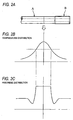
- generated heat causes a sudden rise in temperature at and around the joint portion as shown in FIG. 2B , and raises, particularly, the temperature of the joint portion, up to 1200 degrees (°C) or more.
- the friction welded portion is air-cooled, such that the vicinity of the joint portion, specifically, a portion whose temperature has risen to a high temperature is cooled from a temperature which is below the quenching temperature.
- that portion becomes softer since the hardness of that portion is undesirably lowered (see FIG. 2C ). That is, the hardness of that portion undesirably becomes lower than that of a portion which has not been influenced by the heat.
- the present invention has been made considering the above-mentioned circumferences, and an object of the present invention is to provide a hollow drilling steel rod and a method of manufacturing the same, which enable to prevent lowering in hardness around a joint portion of a stem portion and a thread portion by friction welding, thereby solving the problem in which the portion having a low strength becomes a weak portion in terms of the hardness such that the life of the hollow drilling steel rod is shorter.
- the present invention provides a hollow drilling steel rod comprising a stem portion and a thread portion positioned at an end portion in an axial direction with respect to the stem portion, the hollow drilling steel rod being constituted of a steel having a composition consisting of, in terms of percent by mass:
- the present invention also provides a method of manufacturing said hollow drilling steel rod comprising a stem portion and a thread portion positioned at an end portion in an axial direction with respect to the stem portion, said method comprising:
- a steel having the above-mentioned chemical composition is applied to the steel for the rod, and the thread of the thread portion is previously subjected to a high frequency quenching and the thread portion and the stem portion formed separately from each other are joined by friction welding so as to integrate the thread portion and the stem portion, whereby the hollow drilling steel rod is manufactured.
- the present invention it is possible to perform machining on a short material for the thread portion and also to perform high frequency quenching for hardening of the thread. Therefore, technical difficulties when machining is performed on a long material for a long drilling rod having a seamless continuous integral structure and problems in which a large-sized heat treatment equipment is required may be solved. Consequently, it is possible to easily perform the threading and to easily perform even high frequency quenching as a heat treatment with small-scale equipment.
- a steel containing a low amount of Cr and a high amount of Ni was applied as described above.
- a steel containing a high amount of Cr (2.00% to 5.00% of Cr) and a low amount of Ni (less than 0.50% of Ni) is applied as the steel for the drilling rod, and a high frequency quenching is applied as the heat treatment for achieving the high strength of the thread.
- thread portions positioned at both end portions of the rod in an axial direction may be formed separately from a stem portion, and be joined with the stem portion, thereby manufacturing a hollow drilling steel rod.
- either one of the thread portions may be formed integrally with the stem portion and only the other one of the thread portions may be formed separately from the stem portion and be joined with the stem portion by friction welding, thereby manufacturing a hollow drilling steel rod.
- percent (%) mean “percent (%) by mass” unless otherwise indicated.
- C 0.20% to 0.80% C is effective for increasing both the hardness and strength of the steel. If the amount of C is less than 0.20%, desired hardness and strength cannot be obtained. Meanwhile, if the amount of C exceeds 0.80%, toughness and ductility are impaired. For these reasons, in the present invention, the amount of C is set within a range of 0.20% to 0.80%. Herein, the upper limit of the amount of C is preferably 0.40%.
- Si 0.10% to 0.50% Si is added for deoxidization. In order to obtain that effect, an amount of 0.10% or more is required. However, if the amount exceeds 0.50%, toughness is deteriorated. Therefore, the amount of Si is set within a range of 0.10% to 0.50%.
- the upper limit of the amount of Si is preferably 0.40%.
- Mn 0.10% to 1.00%
- Mn is an element which is effective in deoxidizing steel and is effective also in improving hardenability and obtaining hardness and strength after a heat treatment.
- the amount of Mn is set to be 0.10% or more. However, if the amount of Mn exceeds 1.00%, the toughness is deteriorated. For these reasons, the amount of Mn is set within a range of 0.10% to 1.00%.
- the lower limit of the amount of Mn is preferably 0.30%.
- the upper limit of the amount of Mn is preferably 0.80%.
- P 0.015% or less
- P is an impurity component, and P segregates on grain boundaries, such that the strength at the grain boundaries is lowered and hot workability and toughness are deteriorated. Therefore, it is preferable that the content of P is low.
- the upper limit of the content of P is limited to a value smaller than 0.015%, refining cost increases. For this reason, the upper limit of the content of P is set to 0.015%.
- the upper limit of the amount of P is preferably 0.010%.
- S 0.050% or less S is also an impurity component, and S weakens the strength at the grain boundaries to thereby deteriorate hot workability and toughness. Therefore, it is preferable that the content of S is low. However, if the upper limit of the content of S is excessively limited, refining cost increases. For this reason, the upper limit of the content of S is set to 0.050%. In addition, the upper limit of the amount of S is preferably 0.025%.
- Cu 0.50% or less Cu is one of impurities contained in a raw material, and if a large amount of Cu is contained, hot workability becomes deteriorated.
- the upper limit of the content of Cu is set to 0.50%.
- the upper limit of the amount of Cu is preferably 0.40%.
- Ni less than 0.50%
- Ni is an element which is effective in improving hardenability and obtaining hardness and strength after heat treatment.
- the content of Ni is set to a value less than 0.50%.
- the upper limit of the amount of Ni is preferably 0.30%.
- Cr 2.00% to 5.00% Cr is an element which forms carbide, heightens hardness, and improves wear resistance.
- the amount of Cr is set to 2.00% or more.
- the lower limit of the amount of Cr is preferably 2.80%.
- the upper limit of the amount of Cr is set to 5.00%.
- the upper limit of the amount of Cr is preferably 3.50%.
- Mo 0.20% to 0.80% Mo prevents softening by secondary hardening owing to generation of Mo 2 C during high-temperature heating. Therefore, Mo is effective in preventing the portion around the joint portion from softening during the friction welding.
- the lower limit of the amount of Mo is set to 0.20%.
- the lower limit of the amount of Mo is preferably 0.30%.
- the upper limit of the amount of Mo is set to 0.80%.
- the upper limit of the amount of Mo is preferably 0.60%.
- B 0.0002% to 0.0050%
- B is an element which is effective in improving heat workability and hardenability.
- the lower limit of the content of B is set to 0.0002%.
- the lower limit of the amount of B is preferably 0.0003%.
- the upper limit of the amount of B is set to 0.0050%.
- the upper limit of the amount of B is preferably 0.0020%.
- Ti 0.005% to 0.050% Ti preferentially couples with N so as to precipitate TiN and thus prevents precipitation of BN caused by coupling of B and N, thereby achieving the above-mentioned effects of addition of B. For this reason, in the steel of the present invention, 0.005% or more of Ti is contained. However, if Ti in an amount larger than 0.050% is contained, coarsening of TiN occurs, and fatigue breakage results from the coarsening. For this reason, according to the present invention, the content of Ti is set within a range of 0.005% to 0.050%.
- the lower limit of the amount of Ti is preferably 0.010%.
- the upper limit of the amount of Ti is preferably 0.030%.
- Al 0.005% to 0.050% Al is an element which is effective in deoxidizing steel, and binds with N in preference to B, so as to prevent B from forming BN, resulting in loss of the above-mentioned effects.
- the lower limit of the amount of Al is preferably 0.010%.
- the content of Al is set within a range of 0.005% to 0.050%.
- the upper limit of the amount of Al is preferably 0.040%.
- N 0.050% or less
- N is an impurity component, and N couples with B to pricipitate BN, thereby obstructing the effects of adding B.
- the content of N is limited to 0.050% or less.
- the upper limit of the amount of N is preferably 0.030%.
- the steel used in the invention consists of the above-mentioned elements with the balance being Fe and inevitable impurities.
- the minimal amount thereof present in the steel is the smallest non-zero amount used in the examples as summarized in Table 1.
- the maximum amount thereof present in the steel is the maximum amount used in the examples as summarized in Table 1.
- the member having the male thread portion 14 and the stem portion 12 integrated with each other and the female thread portion 16 were joined with each other by friction welding, thereby manufacturing a drilling rod 10 having a shape shown in FIG. 1A .
- the length L 1 of the male thread portion 14 in an axial direction is 150 mm
- the length L 2 of the stem portion 12 in the axial direction is 3510 mm
- the length L 3 of the female thread portion 16 in the axial direction is 180 mm.
- the male thread 18 has an outer diameter of 50.8 mm and a length L 4 of 93 mm in the axial direction
- the female thread 20 has an inner diameter of 50.8 mm and a length L 5 of 75 mm in the axial direction.
- a drilling rod 10 was manufactured by the same method as the above-mentioned method except that a conventionally-used kind of steel was applied and carburizing and quenching was performed as a heat treatment.
- the high frequency quenching, the carburizing and quenching, and the friction welding were performed under the following conditions.
- Carburizing method Gas carburizing method
- each drilling rod 10 manufactured as described above each of characteristics of hardness of the surface layer, hardness of the center portion, minimum value of the hardness, and impact value was evaluated.
- a hardness test piece S1 including a friction welding portion was taken, and hardnesses of the surface layer and the thick center portion of the joint portion having been subject to the quenching were measured.
- the hardness measurement was performed in accordance with JIS Z 2244 (Vickers Hardness Test-Test Method). The measurement was performed by three test pieces, and an average thereof was used for evaluation.
- the minimum value of hardness represents the hardness of a portion having the lowest hardness around the friction welding portion, and the lowest-hardness portion often corresponds to a portion whose hardness has been lowered by the effect of the quenching.
- the hardnesses of the thick center portion of the test piece S1 were measured at intervals of 1 mm in the longitudinal direction as shown in FIG. 1C , and the minimum value of the hardness (lowest hardness) was found.
- the hardness measurement was performed in accordance with JIS Z 2244 (Vickers Hardness Test-Test Method) by three test pieces, and an average thereof was used for evaluation.
- test pieces S2 for an impact test including the friction welding portion were taken from the thick center portion, and absorbed energy of each V-notched test piece was examined.
- This test was performed in accordance with JIS Z 2242 (Method for Charpy Impact Test of Metallic Materials), and absorbed energy at the V-notched test piece was measured. The measurement was performed by three test pieces, and an average thereof was used for evaluation.
- Table 2 shows the properties evaluated under evaluation standards where the target value of the hardness of 0.5mm surface layer was 590 HV or more, the target value of the hardness of the center portion was 300 HV or more, the target value of the minimum value of the hardness was 300 HV or more, and the target value of the impact value was 15 J/cm 2 or more.
- a comparative example B having the C content of 0.17% which is lower than 0.20% as the lower limit of the content of C defined in the present invention the hardness of the surface layer was low.
- a comparative example C having the C content of 0.95% which is higher than 0.80% as the upper limit of content of C defined in the present invention the impact value was low.
- a comparative example D having the Mn content of 0.05% which is lower than 0.10% as the lower limit of content of Mn defined in the present invention the minimum value of the hardness and the impact value were low.
- a comparative example E having the Mn content of 1.21% which is higher than 1.00% as the upper limit of content of Mn defined in the present invention the impact value was low.
- a comparative example F having the Cr content of 1.78% which is lower than 2.00% as the lower limit of content of Cr defined in the present invention since secondary hardening attributable to Cr carbide precipitation was not sufficiently achieved during the friction welding, the minimum value of the hardness was low.
- a comparative example H having the Mo content of 0.14% which is lower than 0.20% as the lower limit of content of Mo defined in the present invention the minimum value of the hardness was low.
- a comparative example I having the Mo content of 0.92% which is higher than 0.80% as the upper limit of content of Mo defined in the present invention the impact value was low.
- the characteristics such as the surface layer hardness, the center portion hardness, the minimum value of the hardness, and the impact value show good values.
- the present invention can be implemented in various forms without departing from the scope of the claims.
- the present invention can be applied to a drilling rod in which both thread portions are male thread portions, a drilling rod in which both thread portions are female thread portions, etc.
- the present invention relates to a hollow drilling steel rod including a stem portion and a thread portion positioned at an end portion in an axial direction with respect to the stem portion, the hollow drilling steel rod being constituted of a steel having a specific composition described in the present specification, in which the thread portion includes a thread having been subjected to a high frequency quenching, and the thread portion and the stem portion have been constituted separately from each other have been joined by a friction welding.
Landscapes
- Chemical & Material Sciences (AREA)
- Engineering & Computer Science (AREA)
- Mechanical Engineering (AREA)
- Materials Engineering (AREA)
- Metallurgy (AREA)
- Organic Chemistry (AREA)
- Physics & Mathematics (AREA)
- Geology (AREA)
- Life Sciences & Earth Sciences (AREA)
- Mining & Mineral Resources (AREA)
- Crystallography & Structural Chemistry (AREA)
- Thermal Sciences (AREA)
- Environmental & Geological Engineering (AREA)
- Fluid Mechanics (AREA)
- General Life Sciences & Earth Sciences (AREA)
- Geochemistry & Mineralogy (AREA)
- Heat Treatment Of Articles (AREA)
- Pressure Welding/Diffusion-Bonding (AREA)
- Earth Drilling (AREA)
Claims (2)
- Hohle Stahl-Bohrstange, umfassend einen Schaftbereich und einen Gewindebereich, der in der Axialrichtung an einem Endbereich in Bezug auf den Schaftbereich angeordnet ist,
wobei die hohle Stahl-Bohrstange aus einem Stahl mit der folgenden Zusammensetzung, in Masseprozent, besteht:0,20 Prozent bis 0,80 Prozent C,0,10 Prozent bis 0,50 Prozent Si,0,10 Prozent bis 1,00 Prozent Mn,0,015 Prozent oder weniger P,0,050 Prozent oder weniger S,0,50 Prozent oder weniger Cu,weniger als 0,50 Prozent Ni,2,00 Prozent bis 5,00 Prozent Cr,0,20 Prozent bis 0,80 Prozent Mo,0,0002 Prozent bis 0,0050 Prozent B,0,005 Prozent bis 0,050 Prozent Ti,0,005 Prozent bis 0,050 Prozent Al,0,050 Prozent oder weniger N, undder Rest Fe und unvermeidliche Verunreinigungen,
wobei der Gewindebereich ein Gewinde aufweist, welches Hochfrequenz-Quenchen unterzogen wurde, und
wobei der Gewindebereich und der Schaftbereich separat voneinander ausgebildet und durch Reibungsschweißen miteinander verbunden wurden, wobei der Reibungsschweißbereich eine Härte von 300HV oder mehr und einen Impaktwert von 15 J/cm2 oder mehr aufweist. - Verfahren zum Herstellen einer hohlen Stahl-Bohrstange gemäß Anspruch 1, umfassend einen Schaftbereich und einen Gewindebereich, der in der Axialrichtung an einem Endbereich in Bezug auf den Schaftbereich angeordnet ist, das Verfahren umfassend:separates Ausbilden des Schaftbereichs und des Gewindebereichs aus einem Stahl mit der folgenden Zusammensetzung, in Masseprozent:0,20 Prozent bis 0,80 Prozent C,0,10 Prozent bis 0,50 Prozent Si,0,10 Prozent bis 1,00 Prozent Mn,0,015 Prozent oder weniger P,0,050 Prozent oder weniger S,0,50 Prozent oder weniger Cu,weniger als 0,50 Prozent Ni,2,00 Prozent bis 5,00 Prozent Cr,0,20 Prozent bis 0,80 Prozent Mo;0,0002 Prozent bis 0,0050 Prozent B,0,005 Prozent bis 0,050 Prozent Ti,0,005 Prozent bis 0,050 Prozent Al,0,050 Prozent oder weniger N, unddem Rest Fe und unvermeidliche Verunreinigungen,Unterziehen des Gewindes des Gewindebereichs einem Hochfrequenz-Quenchen; und dannmiteinander Verbinden des Gewindebereichs und des Schaftbereichs durch Reibungsschweißen, ohne Wärmebehandlung der gesamten Stange nach dem Verbinden.
Applications Claiming Priority (1)
| Application Number | Priority Date | Filing Date | Title |
|---|---|---|---|
| JP2011033941A JP5523373B2 (ja) | 2011-02-18 | 2011-02-18 | 掘削用中空鋼ロッドとその製造方法 |
Publications (4)
| Publication Number | Publication Date |
|---|---|
| EP2489754A2 EP2489754A2 (de) | 2012-08-22 |
| EP2489754A3 EP2489754A3 (de) | 2013-01-23 |
| EP2489754B1 true EP2489754B1 (de) | 2016-04-27 |
| EP2489754B8 EP2489754B8 (de) | 2016-06-15 |
Family
ID=45655095
Family Applications (1)
| Application Number | Title | Priority Date | Filing Date |
|---|---|---|---|
| EP12001073.1A Active EP2489754B8 (de) | 2011-02-18 | 2012-02-17 | Hohles Stahlbohrgestänge und Herstellungsverfahren dafür |
Country Status (5)
| Country | Link |
|---|---|
| US (1) | US8430977B2 (de) |
| EP (1) | EP2489754B8 (de) |
| JP (1) | JP5523373B2 (de) |
| CA (1) | CA2768121A1 (de) |
| IN (1) | IN2012DE00443A (de) |
Cited By (1)
| Publication number | Priority date | Publication date | Assignee | Title |
|---|---|---|---|---|
| CN107420049A (zh) * | 2017-09-12 | 2017-12-01 | 中国石油集团渤海石油装备制造有限公司 | 一种摩擦焊接式全钛合金钻杆 |
Families Citing this family (21)
| Publication number | Priority date | Publication date | Assignee | Title |
|---|---|---|---|---|
| CN104204260A (zh) * | 2012-03-30 | 2014-12-10 | 爱知制钢株式会社 | 摩擦压焊用钢材及其制造方法 |
| US9816328B2 (en) * | 2012-10-16 | 2017-11-14 | Smith International, Inc. | Friction welded heavy weight drill pipes |
| EP2746419A1 (de) * | 2012-12-20 | 2014-06-25 | Sandvik Intellectual Property AB | Bainitstahl für Gesteinsbohrkomponenten |
| RU2552796C2 (ru) * | 2013-07-10 | 2015-06-10 | Открытое акционерное общество "Синарский трубный завод" (ОАО "СинТЗ") | Бурильная труба высокопрочная |
| CN104632091B (zh) * | 2013-11-15 | 2017-07-14 | 中国石油天然气股份有限公司 | 一种小直径排水采气管柱 |
| PL3095954T3 (pl) | 2015-05-22 | 2024-08-05 | Sandvik Intellectual Property Ab | Żerdź wiertnicza lub łącznik ze wzmocnionym złączem czopowym |
| CN105132665A (zh) * | 2015-09-14 | 2015-12-09 | 丰达石油装备股份有限公司 | 超音频淬火工艺在地质钻探钎杆生产中的应用 |
| WO2017051632A1 (ja) * | 2015-09-25 | 2017-03-30 | 新日鐵住金株式会社 | ピアサープラグ及びその製造方法 |
| CN106756592B (zh) * | 2017-01-12 | 2018-04-03 | 河北工程大学 | 隧道盾构施工用滚刀刀圈 |
| WO2019087510A1 (ja) * | 2017-11-02 | 2019-05-09 | 日本製鉄株式会社 | ピアサープラグ及びその製造方法 |
| CN108546880A (zh) * | 2018-05-15 | 2018-09-18 | 本钢板材股份有限公司 | 钎钢BG22SiMnNi2CrMoA及其制备方法 |
| CN109295381A (zh) * | 2018-11-27 | 2019-02-01 | 胡敏 | 一种钻头用合金钢材料及其制备方法 |
| US11143624B2 (en) | 2019-05-14 | 2021-10-12 | King Abdulaziz University | Detection of friction stir welding defects using specific damping capacity |
| JP2021025104A (ja) * | 2019-08-07 | 2021-02-22 | 国立大学法人大阪大学 | 固相接合用鋼、固相接合用鋼材、固相接合継手及び固相接合構造物 |
| WO2021033647A1 (ja) * | 2019-08-20 | 2021-02-25 | 日本製鉄株式会社 | 接合継手、自動車用部材、及び接合継手の製造方法 |
| CN111485069A (zh) * | 2020-05-27 | 2020-08-04 | 中地装(无锡)钻探工具有限公司 | 一种钻杆及其连接处螺纹表面的处理工艺 |
| CN112282718B (zh) * | 2020-11-05 | 2022-12-02 | 中国石油天然气股份有限公司 | 一种侧钻井和小井眼井用组合管串及使用方法 |
| JPWO2023162502A1 (de) * | 2022-02-25 | 2023-08-31 | ||
| JP7666477B2 (ja) * | 2022-09-29 | 2025-04-22 | Jfeスチール株式会社 | 鋼板 |
| CN115679221B (zh) * | 2022-11-21 | 2024-01-26 | 宝武杰富意特殊钢有限公司 | 钎具钢的制备方法 |
| CN116197612A (zh) * | 2022-12-28 | 2023-06-02 | 洛阳拓岩机械设备有限公司 | 一种钎具快接头及其制造方法 |
Family Cites Families (18)
| Publication number | Priority date | Publication date | Assignee | Title |
|---|---|---|---|---|
| JPS62230955A (ja) * | 1986-03-31 | 1987-10-09 | Nippon Steel Corp | 耐食性の優れた堀削ドリルパイプ用鋼 |
| SE506178C2 (sv) * | 1996-01-22 | 1997-11-17 | Sandvik Ab | Friktionssvetsad produkt för bergborrning samt förfarande för tillverkning av produkten |
| SE507440C2 (sv) * | 1996-06-20 | 1998-06-08 | Sandvik Ab | Friktionssvetsad borrstång samt förfarande för tillverkning av borrstången |
| SE507439C2 (sv) | 1996-06-24 | 1998-06-08 | Sandvik Ab | Friktionssvetsad borrstång samt förfarande för tillverkning av borrstången |
| JP2000204432A (ja) * | 1999-01-12 | 2000-07-25 | Ntn Corp | 動力伝達軸 |
| JP2001342788A (ja) | 2000-05-31 | 2001-12-14 | Daido Steel Co Ltd | 削岩機用ロッド |
| JP2002294404A (ja) * | 2001-03-29 | 2002-10-09 | Kawasaki Steel Corp | 摩擦圧接に適した高炭素熱延鋼材およびその製造方法 |
| JP3858072B2 (ja) * | 2001-11-28 | 2006-12-13 | 独立行政法人海洋研究開発機構 | ドリルパイプおよびその製造方法 |
| SE520893C2 (sv) * | 2002-02-21 | 2003-09-09 | Sandvik Ab | Element för slående bergborrning, innefattande åtminstone en gänga |
| SE523940C2 (sv) * | 2002-03-12 | 2004-06-08 | Sandvik Ab | Borrelement för bergborrning och en metod för att tillverka borrelementet |
| WO2006104023A1 (ja) * | 2005-03-25 | 2006-10-05 | Sumitomo Metal Industries, Ltd. | 高周波焼入れ中空駆動軸 |
| JP4854981B2 (ja) * | 2005-04-15 | 2012-01-18 | 新日本製鐵株式会社 | 耐疲労特性に優れた摩擦圧接接合部品およびその疲労特性向上方法 |
| CN100422374C (zh) | 2006-04-04 | 2008-10-01 | 无锡西姆莱斯石油专用管制造有限公司 | 防硫钻杆及其制造方法 |
| CN2893126Y (zh) | 2006-05-31 | 2007-04-25 | 贵阳林海有限公司 | 加强钻杆 |
| JP2008111146A (ja) * | 2006-10-30 | 2008-05-15 | Jfe Steel Kk | 掘削工具刃用鋼または削岩工具刃用鋼、およびその製造方法 |
| CN201301670Y (zh) * | 2008-04-23 | 2009-09-02 | 长年Tm公司 | 双钢冲击钻杆 |
| JP5503195B2 (ja) * | 2009-06-18 | 2014-05-28 | 株式会社神戸製鋼所 | 摩擦圧接に適した機械構造用鋼材およびその製造方法、摩擦圧接部品 |
| JP2011033941A (ja) | 2009-08-04 | 2011-02-17 | Nippon Telegr & Teleph Corp <Ntt> | 中赤外光源およびそれを用いた赤外光吸収分析装置 |
-
2011
- 2011-02-18 JP JP2011033941A patent/JP5523373B2/ja not_active Expired - Fee Related
-
2012
- 2012-02-16 IN IN443DE2012 patent/IN2012DE00443A/en unknown
- 2012-02-16 CA CA2768121A patent/CA2768121A1/en not_active Abandoned
- 2012-02-17 US US13/399,063 patent/US8430977B2/en active Active
- 2012-02-17 EP EP12001073.1A patent/EP2489754B8/de active Active
Cited By (1)
| Publication number | Priority date | Publication date | Assignee | Title |
|---|---|---|---|---|
| CN107420049A (zh) * | 2017-09-12 | 2017-12-01 | 中国石油集团渤海石油装备制造有限公司 | 一种摩擦焊接式全钛合金钻杆 |
Also Published As
| Publication number | Publication date |
|---|---|
| US20120211127A1 (en) | 2012-08-23 |
| EP2489754B8 (de) | 2016-06-15 |
| JP2012172344A (ja) | 2012-09-10 |
| JP5523373B2 (ja) | 2014-06-18 |
| IN2012DE00443A (de) | 2015-06-05 |
| EP2489754A2 (de) | 2012-08-22 |
| EP2489754A3 (de) | 2013-01-23 |
| CA2768121A1 (en) | 2012-08-18 |
| US8430977B2 (en) | 2013-04-30 |
Similar Documents
| Publication | Publication Date | Title |
|---|---|---|
| EP2489754B1 (de) | Hohles Stahlbohrgestänge und Herstellungsverfahren dafür | |
| EP3031943B1 (de) | Nahtloses stahlrohr für ein leitungsrohr und verfahren zur herstellung davon | |
| TWI485267B (zh) | 轉動疲勞特性優異之軸承用鋼材及其製造方法 | |
| JP6152930B1 (ja) | 油井用低合金高強度厚肉継目無鋼管 | |
| EP2060644A1 (de) | Martensitischer nichtrostender stahl | |
| EP3144407B1 (de) | Verfahren zur herstellung von nahtloses stahlrohr für ein leitungsrohr | |
| US11628481B2 (en) | Centrifugally cast composite roll for rolling and method of manufacturing the same | |
| JP2012207244A (ja) | 肌焼鋼およびその製造方法、並びに肌焼鋼を用いた機械構造部品 | |
| WO2013105536A1 (ja) | 耐摩耗溶接鋼管およびその製造方法 | |
| WO2014192251A1 (ja) | サワー環境で使用されるラインパイプ用継目無鋼管 | |
| EP4086016A1 (de) | Rohr aus edelstahl und verfahren zur herstellung davon | |
| JP4632931B2 (ja) | 冷間加工性に優れる高周波焼入れ用鋼及びその製造方法 | |
| EP3018220B1 (de) | Verfahren zur herstellung eines kohlenstoffreichen widerstandsgeschweisstes stahlrohrs und automobilteil | |
| KR102639340B1 (ko) | 중공 스태빌라이저용 전봉 강관 | |
| JP5874402B2 (ja) | 耐溶接割れ性と耐スラリー腐食摩耗性に優れた溶接鋼管およびその製造方法 | |
| EP2608920B1 (de) | Abbrennstumpfgeschweisste trägerkomponente | |
| TWI480387B (zh) | 冷加工性優異之軸承用鋼材及其製造方法 | |
| EP3748027B1 (de) | Bolzen | |
| US9976197B2 (en) | Method for producing journal part of 9 to 12% Cr steel turbine rotor, and journal part produced by the method | |
| KR101449142B1 (ko) | 싱크롤러 | |
| JP2546416B2 (ja) | 形鋼圧延ロール用スリーブとその製造方法 | |
| US20240167116A1 (en) | Steel wire for machine structural parts and method for manufacturing the same | |
| JP2007277654A (ja) | 冷間鍛造部品、それを得るための製造方法および鋼材 | |
| WO2023152906A1 (ja) | 自動車部品用電縫鋼管、及び、自動車部品の製造方法 | |
| US20160363167A1 (en) | Steel composition for flash-butt welding |
Legal Events
| Date | Code | Title | Description |
|---|---|---|---|
| PUAI | Public reference made under article 153(3) epc to a published international application that has entered the european phase |
Free format text: ORIGINAL CODE: 0009012 |
|
| AK | Designated contracting states |
Kind code of ref document: A2 Designated state(s): AL AT BE BG CH CY CZ DE DK EE ES FI FR GB GR HR HU IE IS IT LI LT LU LV MC MK MT NL NO PL PT RO RS SE SI SK SM TR |
|
| AX | Request for extension of the european patent |
Extension state: BA ME |
|
| PUAL | Search report despatched |
Free format text: ORIGINAL CODE: 0009013 |
|
| AK | Designated contracting states |
Kind code of ref document: A3 Designated state(s): AL AT BE BG CH CY CZ DE DK EE ES FI FR GB GR HR HU IE IS IT LI LT LU LV MC MK MT NL NO PL PT RO RS SE SI SK SM TR |
|
| AX | Request for extension of the european patent |
Extension state: BA ME |
|
| RIC1 | Information provided on ipc code assigned before grant |
Ipc: C22C 38/54 20060101ALI20121218BHEP Ipc: C22C 38/02 20060101AFI20121218BHEP Ipc: C21D 1/18 20060101ALI20121218BHEP Ipc: E21B 17/00 20060101ALI20121218BHEP Ipc: C21D 9/08 20060101ALI20121218BHEP Ipc: C22C 38/04 20060101ALI20121218BHEP Ipc: C22C 38/06 20060101ALI20121218BHEP Ipc: C22C 38/42 20060101ALI20121218BHEP Ipc: C22C 38/50 20060101ALI20121218BHEP Ipc: C22C 38/44 20060101ALI20121218BHEP |
|
| 17P | Request for examination filed |
Effective date: 20130625 |
|
| RBV | Designated contracting states (corrected) |
Designated state(s): AL AT BE BG CH CY CZ DE DK EE ES FI FR GB GR HR HU IE IS IT LI LT LU LV MC MK MT NL NO PL PT RO RS SE SI SK SM TR |
|
| GRAP | Despatch of communication of intention to grant a patent |
Free format text: ORIGINAL CODE: EPIDOSNIGR1 |
|
| RIC1 | Information provided on ipc code assigned before grant |
Ipc: C22C 38/42 20060101ALI20150907BHEP Ipc: C21D 1/18 20060101ALI20150907BHEP Ipc: C21D 9/08 20060101ALI20150907BHEP Ipc: C22C 38/50 20060101ALI20150907BHEP Ipc: C21D 1/42 20060101ALN20150907BHEP Ipc: C22C 38/54 20060101ALI20150907BHEP Ipc: E21B 17/042 20060101ALI20150907BHEP Ipc: C21D 9/50 20060101ALI20150907BHEP Ipc: C22C 38/04 20060101ALI20150907BHEP Ipc: C22C 38/44 20060101ALI20150907BHEP Ipc: E21B 17/00 20060101ALI20150907BHEP Ipc: C22C 38/02 20060101AFI20150907BHEP Ipc: C22C 38/06 20060101ALI20150907BHEP |
|
| INTG | Intention to grant announced |
Effective date: 20150924 |
|
| GRAS | Grant fee paid |
Free format text: ORIGINAL CODE: EPIDOSNIGR3 |
|
| GRAA | (expected) grant |
Free format text: ORIGINAL CODE: 0009210 |
|
| GRAT | Correction requested after decision to grant or after decision to maintain patent in amended form |
Free format text: ORIGINAL CODE: EPIDOSNCDEC |
|
| AK | Designated contracting states |
Kind code of ref document: B1 Designated state(s): AL AT BE BG CH CY CZ DE DK EE ES FI FR GB GR HR HU IE IS IT LI LT LU LV MC MK MT NL NO PL PT RO RS SE SI SK SM TR |
|
| REG | Reference to a national code |
Ref country code: GB Ref legal event code: FG4D |
|
| REG | Reference to a national code |
Ref country code: CH Ref legal event code: EP |
|
| REG | Reference to a national code |
Ref country code: AT Ref legal event code: REF Ref document number: 794903 Country of ref document: AT Kind code of ref document: T Effective date: 20160515 |
|
| RAP2 | Party data changed (patent owner data changed or rights of a patent transferred) |
Owner name: MITSUBISHI MATERIALS CORPORATION |
|
| REG | Reference to a national code |
Ref country code: IE Ref legal event code: FG4D |
|
| REG | Reference to a national code |
Ref country code: DE Ref legal event code: R096 Ref document number: 602012017507 Country of ref document: DE |
|
| REG | Reference to a national code |
Ref country code: SE Ref legal event code: TRGR |
|
| REG | Reference to a national code |
Ref country code: LT Ref legal event code: MG4D |
|
| REG | Reference to a national code |
Ref country code: NL Ref legal event code: MP Effective date: 20160427 |
|
| REG | Reference to a national code |
Ref country code: AT Ref legal event code: MK05 Ref document number: 794903 Country of ref document: AT Kind code of ref document: T Effective date: 20160427 |
|
| PG25 | Lapsed in a contracting state [announced via postgrant information from national office to epo] |
Ref country code: NL Free format text: LAPSE BECAUSE OF FAILURE TO SUBMIT A TRANSLATION OF THE DESCRIPTION OR TO PAY THE FEE WITHIN THE PRESCRIBED TIME-LIMIT Effective date: 20160427 |
|
| PG25 | Lapsed in a contracting state [announced via postgrant information from national office to epo] |
Ref country code: LT Free format text: LAPSE BECAUSE OF FAILURE TO SUBMIT A TRANSLATION OF THE DESCRIPTION OR TO PAY THE FEE WITHIN THE PRESCRIBED TIME-LIMIT Effective date: 20160427 Ref country code: FI Free format text: LAPSE BECAUSE OF FAILURE TO SUBMIT A TRANSLATION OF THE DESCRIPTION OR TO PAY THE FEE WITHIN THE PRESCRIBED TIME-LIMIT Effective date: 20160427 Ref country code: PL Free format text: LAPSE BECAUSE OF FAILURE TO SUBMIT A TRANSLATION OF THE DESCRIPTION OR TO PAY THE FEE WITHIN THE PRESCRIBED TIME-LIMIT Effective date: 20160427 Ref country code: NO Free format text: LAPSE BECAUSE OF FAILURE TO SUBMIT A TRANSLATION OF THE DESCRIPTION OR TO PAY THE FEE WITHIN THE PRESCRIBED TIME-LIMIT Effective date: 20160727 |
|
| PG25 | Lapsed in a contracting state [announced via postgrant information from national office to epo] |
Ref country code: PT Free format text: LAPSE BECAUSE OF FAILURE TO SUBMIT A TRANSLATION OF THE DESCRIPTION OR TO PAY THE FEE WITHIN THE PRESCRIBED TIME-LIMIT Effective date: 20160829 Ref country code: LV Free format text: LAPSE BECAUSE OF FAILURE TO SUBMIT A TRANSLATION OF THE DESCRIPTION OR TO PAY THE FEE WITHIN THE PRESCRIBED TIME-LIMIT Effective date: 20160427 Ref country code: HR Free format text: LAPSE BECAUSE OF FAILURE TO SUBMIT A TRANSLATION OF THE DESCRIPTION OR TO PAY THE FEE WITHIN THE PRESCRIBED TIME-LIMIT Effective date: 20160427 Ref country code: ES Free format text: LAPSE BECAUSE OF FAILURE TO SUBMIT A TRANSLATION OF THE DESCRIPTION OR TO PAY THE FEE WITHIN THE PRESCRIBED TIME-LIMIT Effective date: 20160427 Ref country code: GR Free format text: LAPSE BECAUSE OF FAILURE TO SUBMIT A TRANSLATION OF THE DESCRIPTION OR TO PAY THE FEE WITHIN THE PRESCRIBED TIME-LIMIT Effective date: 20160728 Ref country code: RS Free format text: LAPSE BECAUSE OF FAILURE TO SUBMIT A TRANSLATION OF THE DESCRIPTION OR TO PAY THE FEE WITHIN THE PRESCRIBED TIME-LIMIT Effective date: 20160427 Ref country code: AT Free format text: LAPSE BECAUSE OF FAILURE TO SUBMIT A TRANSLATION OF THE DESCRIPTION OR TO PAY THE FEE WITHIN THE PRESCRIBED TIME-LIMIT Effective date: 20160427 |
|
| PG25 | Lapsed in a contracting state [announced via postgrant information from national office to epo] |
Ref country code: BE Free format text: LAPSE BECAUSE OF FAILURE TO SUBMIT A TRANSLATION OF THE DESCRIPTION OR TO PAY THE FEE WITHIN THE PRESCRIBED TIME-LIMIT Effective date: 20160427 Ref country code: IT Free format text: LAPSE BECAUSE OF FAILURE TO SUBMIT A TRANSLATION OF THE DESCRIPTION OR TO PAY THE FEE WITHIN THE PRESCRIBED TIME-LIMIT Effective date: 20160427 |
|
| REG | Reference to a national code |
Ref country code: DE Ref legal event code: R097 Ref document number: 602012017507 Country of ref document: DE |
|
| PG25 | Lapsed in a contracting state [announced via postgrant information from national office to epo] |
Ref country code: SK Free format text: LAPSE BECAUSE OF FAILURE TO SUBMIT A TRANSLATION OF THE DESCRIPTION OR TO PAY THE FEE WITHIN THE PRESCRIBED TIME-LIMIT Effective date: 20160427 Ref country code: CZ Free format text: LAPSE BECAUSE OF FAILURE TO SUBMIT A TRANSLATION OF THE DESCRIPTION OR TO PAY THE FEE WITHIN THE PRESCRIBED TIME-LIMIT Effective date: 20160427 Ref country code: RO Free format text: LAPSE BECAUSE OF FAILURE TO SUBMIT A TRANSLATION OF THE DESCRIPTION OR TO PAY THE FEE WITHIN THE PRESCRIBED TIME-LIMIT Effective date: 20160427 Ref country code: DK Free format text: LAPSE BECAUSE OF FAILURE TO SUBMIT A TRANSLATION OF THE DESCRIPTION OR TO PAY THE FEE WITHIN THE PRESCRIBED TIME-LIMIT Effective date: 20160427 Ref country code: EE Free format text: LAPSE BECAUSE OF FAILURE TO SUBMIT A TRANSLATION OF THE DESCRIPTION OR TO PAY THE FEE WITHIN THE PRESCRIBED TIME-LIMIT Effective date: 20160427 |
|
| PG25 | Lapsed in a contracting state [announced via postgrant information from national office to epo] |
Ref country code: SM Free format text: LAPSE BECAUSE OF FAILURE TO SUBMIT A TRANSLATION OF THE DESCRIPTION OR TO PAY THE FEE WITHIN THE PRESCRIBED TIME-LIMIT Effective date: 20160427 |
|
| PLBE | No opposition filed within time limit |
Free format text: ORIGINAL CODE: 0009261 |
|
| STAA | Information on the status of an ep patent application or granted ep patent |
Free format text: STATUS: NO OPPOSITION FILED WITHIN TIME LIMIT |
|
| 26N | No opposition filed |
Effective date: 20170130 |
|
| PG25 | Lapsed in a contracting state [announced via postgrant information from national office to epo] |
Ref country code: SI Free format text: LAPSE BECAUSE OF FAILURE TO SUBMIT A TRANSLATION OF THE DESCRIPTION OR TO PAY THE FEE WITHIN THE PRESCRIBED TIME-LIMIT Effective date: 20160427 |
|
| REG | Reference to a national code |
Ref country code: DE Ref legal event code: R119 Ref document number: 602012017507 Country of ref document: DE |
|
| PG25 | Lapsed in a contracting state [announced via postgrant information from national office to epo] |
Ref country code: MC Free format text: LAPSE BECAUSE OF FAILURE TO SUBMIT A TRANSLATION OF THE DESCRIPTION OR TO PAY THE FEE WITHIN THE PRESCRIBED TIME-LIMIT Effective date: 20160427 |
|
| REG | Reference to a national code |
Ref country code: CH Ref legal event code: PL |
|
| PG25 | Lapsed in a contracting state [announced via postgrant information from national office to epo] |
Ref country code: LI Free format text: LAPSE BECAUSE OF NON-PAYMENT OF DUE FEES Effective date: 20170228 Ref country code: CH Free format text: LAPSE BECAUSE OF NON-PAYMENT OF DUE FEES Effective date: 20170228 |
|
| REG | Reference to a national code |
Ref country code: IE Ref legal event code: MM4A |
|
| REG | Reference to a national code |
Ref country code: FR Ref legal event code: ST Effective date: 20171031 |
|
| PG25 | Lapsed in a contracting state [announced via postgrant information from national office to epo] |
Ref country code: LU Free format text: LAPSE BECAUSE OF NON-PAYMENT OF DUE FEES Effective date: 20170217 |
|
| PG25 | Lapsed in a contracting state [announced via postgrant information from national office to epo] |
Ref country code: DE Free format text: LAPSE BECAUSE OF NON-PAYMENT OF DUE FEES Effective date: 20170901 Ref country code: FR Free format text: LAPSE BECAUSE OF NON-PAYMENT OF DUE FEES Effective date: 20170228 |
|
| PG25 | Lapsed in a contracting state [announced via postgrant information from national office to epo] |
Ref country code: IE Free format text: LAPSE BECAUSE OF NON-PAYMENT OF DUE FEES Effective date: 20170217 |
|
| PG25 | Lapsed in a contracting state [announced via postgrant information from national office to epo] |
Ref country code: MT Free format text: LAPSE BECAUSE OF NON-PAYMENT OF DUE FEES Effective date: 20170217 |
|
| PG25 | Lapsed in a contracting state [announced via postgrant information from national office to epo] |
Ref country code: AL Free format text: LAPSE BECAUSE OF FAILURE TO SUBMIT A TRANSLATION OF THE DESCRIPTION OR TO PAY THE FEE WITHIN THE PRESCRIBED TIME-LIMIT Effective date: 20160427 |
|
| PG25 | Lapsed in a contracting state [announced via postgrant information from national office to epo] |
Ref country code: HU Free format text: LAPSE BECAUSE OF FAILURE TO SUBMIT A TRANSLATION OF THE DESCRIPTION OR TO PAY THE FEE WITHIN THE PRESCRIBED TIME-LIMIT; INVALID AB INITIO Effective date: 20120217 |
|
| PG25 | Lapsed in a contracting state [announced via postgrant information from national office to epo] |
Ref country code: BG Free format text: LAPSE BECAUSE OF FAILURE TO SUBMIT A TRANSLATION OF THE DESCRIPTION OR TO PAY THE FEE WITHIN THE PRESCRIBED TIME-LIMIT Effective date: 20160427 |
|
| PG25 | Lapsed in a contracting state [announced via postgrant information from national office to epo] |
Ref country code: CY Free format text: LAPSE BECAUSE OF NON-PAYMENT OF DUE FEES Effective date: 20160427 |
|
| PG25 | Lapsed in a contracting state [announced via postgrant information from national office to epo] |
Ref country code: MK Free format text: LAPSE BECAUSE OF FAILURE TO SUBMIT A TRANSLATION OF THE DESCRIPTION OR TO PAY THE FEE WITHIN THE PRESCRIBED TIME-LIMIT Effective date: 20160427 |
|
| PG25 | Lapsed in a contracting state [announced via postgrant information from national office to epo] |
Ref country code: TR Free format text: LAPSE BECAUSE OF FAILURE TO SUBMIT A TRANSLATION OF THE DESCRIPTION OR TO PAY THE FEE WITHIN THE PRESCRIBED TIME-LIMIT Effective date: 20160427 |
|
| PG25 | Lapsed in a contracting state [announced via postgrant information from national office to epo] |
Ref country code: IS Free format text: LAPSE BECAUSE OF FAILURE TO SUBMIT A TRANSLATION OF THE DESCRIPTION OR TO PAY THE FEE WITHIN THE PRESCRIBED TIME-LIMIT Effective date: 20160827 |
|
| REG | Reference to a national code |
Ref country code: GB Ref legal event code: 732E Free format text: REGISTERED BETWEEN 20211125 AND 20211201 |
|
| PGFP | Annual fee paid to national office [announced via postgrant information from national office to epo] |
Ref country code: SE Payment date: 20251230 Year of fee payment: 15 |
|
| PGFP | Annual fee paid to national office [announced via postgrant information from national office to epo] |
Ref country code: GB Payment date: 20260106 Year of fee payment: 15 |