EP2489664A1 - Fluorene-containing aromatic compound, material for organic electroluminescent element, and organic electroluminescent element using same - Google Patents
Fluorene-containing aromatic compound, material for organic electroluminescent element, and organic electroluminescent element using same Download PDFInfo
- Publication number
- EP2489664A1 EP2489664A1 EP10823450A EP10823450A EP2489664A1 EP 2489664 A1 EP2489664 A1 EP 2489664A1 EP 10823450 A EP10823450 A EP 10823450A EP 10823450 A EP10823450 A EP 10823450A EP 2489664 A1 EP2489664 A1 EP 2489664A1
- Authority
- EP
- European Patent Office
- Prior art keywords
- group
- substituted
- ring
- carbon atoms
- unsubstituted
- Prior art date
- Legal status (The legal status is an assumption and is not a legal conclusion. Google has not performed a legal analysis and makes no representation as to the accuracy of the status listed.)
- Withdrawn
Links
- 0 CC1(C)C2=*=CC(C(CCC(CCC3)CC3C3C4C#CNC4C(C4)(CCCC5)C4C5*3)NC(c3cccc*3)N)C=*2C2C1C=*CC2 Chemical compound CC1(C)C2=*=CC(C(CCC(CCC3)CC3C3C4C#CNC4C(C4)(CCCC5)C4C5*3)NC(c3cccc*3)N)C=*2C2C1C=*CC2 0.000 description 11
Images

Classifications
-
- C—CHEMISTRY; METALLURGY
- C07—ORGANIC CHEMISTRY
- C07D—HETEROCYCLIC COMPOUNDS
- C07D403/00—Heterocyclic compounds containing two or more hetero rings, having nitrogen atoms as the only ring hetero atoms, not provided for by group C07D401/00
- C07D403/02—Heterocyclic compounds containing two or more hetero rings, having nitrogen atoms as the only ring hetero atoms, not provided for by group C07D401/00 containing two hetero rings
- C07D403/10—Heterocyclic compounds containing two or more hetero rings, having nitrogen atoms as the only ring hetero atoms, not provided for by group C07D401/00 containing two hetero rings linked by a carbon chain containing aromatic rings
-
- C—CHEMISTRY; METALLURGY
- C07—ORGANIC CHEMISTRY
- C07D—HETEROCYCLIC COMPOUNDS
- C07D307/00—Heterocyclic compounds containing five-membered rings having one oxygen atom as the only ring hetero atom
- C07D307/77—Heterocyclic compounds containing five-membered rings having one oxygen atom as the only ring hetero atom ortho- or peri-condensed with carbocyclic rings or ring systems
- C07D307/91—Dibenzofurans; Hydrogenated dibenzofurans
-
- C—CHEMISTRY; METALLURGY
- C07—ORGANIC CHEMISTRY
- C07D—HETEROCYCLIC COMPOUNDS
- C07D209/00—Heterocyclic compounds containing five-membered rings, condensed with other rings, with one nitrogen atom as the only ring hetero atom
- C07D209/56—Ring systems containing three or more rings
- C07D209/80—[b, c]- or [b, d]-condensed
- C07D209/82—Carbazoles; Hydrogenated carbazoles
- C07D209/86—Carbazoles; Hydrogenated carbazoles with only hydrogen atoms, hydrocarbon or substituted hydrocarbon radicals, directly attached to carbon atoms of the ring system
-
- C—CHEMISTRY; METALLURGY
- C07—ORGANIC CHEMISTRY
- C07D—HETEROCYCLIC COMPOUNDS
- C07D401/00—Heterocyclic compounds containing two or more hetero rings, having nitrogen atoms as the only ring hetero atoms, at least one ring being a six-membered ring with only one nitrogen atom
- C07D401/02—Heterocyclic compounds containing two or more hetero rings, having nitrogen atoms as the only ring hetero atoms, at least one ring being a six-membered ring with only one nitrogen atom containing two hetero rings
- C07D401/10—Heterocyclic compounds containing two or more hetero rings, having nitrogen atoms as the only ring hetero atoms, at least one ring being a six-membered ring with only one nitrogen atom containing two hetero rings linked by a carbon chain containing aromatic rings
-
- C—CHEMISTRY; METALLURGY
- C07—ORGANIC CHEMISTRY
- C07D—HETEROCYCLIC COMPOUNDS
- C07D401/00—Heterocyclic compounds containing two or more hetero rings, having nitrogen atoms as the only ring hetero atoms, at least one ring being a six-membered ring with only one nitrogen atom
- C07D401/14—Heterocyclic compounds containing two or more hetero rings, having nitrogen atoms as the only ring hetero atoms, at least one ring being a six-membered ring with only one nitrogen atom containing three or more hetero rings
-
- C—CHEMISTRY; METALLURGY
- C07—ORGANIC CHEMISTRY
- C07D—HETEROCYCLIC COMPOUNDS
- C07D403/00—Heterocyclic compounds containing two or more hetero rings, having nitrogen atoms as the only ring hetero atoms, not provided for by group C07D401/00
- C07D403/02—Heterocyclic compounds containing two or more hetero rings, having nitrogen atoms as the only ring hetero atoms, not provided for by group C07D401/00 containing two hetero rings
- C07D403/04—Heterocyclic compounds containing two or more hetero rings, having nitrogen atoms as the only ring hetero atoms, not provided for by group C07D401/00 containing two hetero rings directly linked by a ring-member-to-ring-member bond
-
- C—CHEMISTRY; METALLURGY
- C07—ORGANIC CHEMISTRY
- C07D—HETEROCYCLIC COMPOUNDS
- C07D403/00—Heterocyclic compounds containing two or more hetero rings, having nitrogen atoms as the only ring hetero atoms, not provided for by group C07D401/00
- C07D403/14—Heterocyclic compounds containing two or more hetero rings, having nitrogen atoms as the only ring hetero atoms, not provided for by group C07D401/00 containing three or more hetero rings
-
- C—CHEMISTRY; METALLURGY
- C07—ORGANIC CHEMISTRY
- C07D—HETEROCYCLIC COMPOUNDS
- C07D405/00—Heterocyclic compounds containing both one or more hetero rings having oxygen atoms as the only ring hetero atoms, and one or more rings having nitrogen as the only ring hetero atom
- C07D405/14—Heterocyclic compounds containing both one or more hetero rings having oxygen atoms as the only ring hetero atoms, and one or more rings having nitrogen as the only ring hetero atom containing three or more hetero rings
-
- C—CHEMISTRY; METALLURGY
- C07—ORGANIC CHEMISTRY
- C07D—HETEROCYCLIC COMPOUNDS
- C07D409/00—Heterocyclic compounds containing two or more hetero rings, at least one ring having sulfur atoms as the only ring hetero atoms
- C07D409/02—Heterocyclic compounds containing two or more hetero rings, at least one ring having sulfur atoms as the only ring hetero atoms containing two hetero rings
- C07D409/12—Heterocyclic compounds containing two or more hetero rings, at least one ring having sulfur atoms as the only ring hetero atoms containing two hetero rings linked by a chain containing hetero atoms as chain links
-
- C—CHEMISTRY; METALLURGY
- C07—ORGANIC CHEMISTRY
- C07D—HETEROCYCLIC COMPOUNDS
- C07D409/00—Heterocyclic compounds containing two or more hetero rings, at least one ring having sulfur atoms as the only ring hetero atoms
- C07D409/14—Heterocyclic compounds containing two or more hetero rings, at least one ring having sulfur atoms as the only ring hetero atoms containing three or more hetero rings
-
- C—CHEMISTRY; METALLURGY
- C07—ORGANIC CHEMISTRY
- C07D—HETEROCYCLIC COMPOUNDS
- C07D471/00—Heterocyclic compounds containing nitrogen atoms as the only ring hetero atoms in the condensed system, at least one ring being a six-membered ring with one nitrogen atom, not provided for by groups C07D451/00 - C07D463/00
- C07D471/02—Heterocyclic compounds containing nitrogen atoms as the only ring hetero atoms in the condensed system, at least one ring being a six-membered ring with one nitrogen atom, not provided for by groups C07D451/00 - C07D463/00 in which the condensed system contains two hetero rings
- C07D471/04—Ortho-condensed systems
-
- C—CHEMISTRY; METALLURGY
- C09—DYES; PAINTS; POLISHES; NATURAL RESINS; ADHESIVES; COMPOSITIONS NOT OTHERWISE PROVIDED FOR; APPLICATIONS OF MATERIALS NOT OTHERWISE PROVIDED FOR
- C09B—ORGANIC DYES OR CLOSELY-RELATED COMPOUNDS FOR PRODUCING DYES, e.g. PIGMENTS; MORDANTS; LAKES
- C09B57/00—Other synthetic dyes of known constitution
-
- C—CHEMISTRY; METALLURGY
- C09—DYES; PAINTS; POLISHES; NATURAL RESINS; ADHESIVES; COMPOSITIONS NOT OTHERWISE PROVIDED FOR; APPLICATIONS OF MATERIALS NOT OTHERWISE PROVIDED FOR
- C09B—ORGANIC DYES OR CLOSELY-RELATED COMPOUNDS FOR PRODUCING DYES, e.g. PIGMENTS; MORDANTS; LAKES
- C09B57/00—Other synthetic dyes of known constitution
- C09B57/008—Triarylamine dyes containing no other chromophores
-
- C—CHEMISTRY; METALLURGY
- C09—DYES; PAINTS; POLISHES; NATURAL RESINS; ADHESIVES; COMPOSITIONS NOT OTHERWISE PROVIDED FOR; APPLICATIONS OF MATERIALS NOT OTHERWISE PROVIDED FOR
- C09B—ORGANIC DYES OR CLOSELY-RELATED COMPOUNDS FOR PRODUCING DYES, e.g. PIGMENTS; MORDANTS; LAKES
- C09B57/00—Other synthetic dyes of known constitution
- C09B57/10—Metal complexes of organic compounds not being dyes in uncomplexed form
-
- C—CHEMISTRY; METALLURGY
- C09—DYES; PAINTS; POLISHES; NATURAL RESINS; ADHESIVES; COMPOSITIONS NOT OTHERWISE PROVIDED FOR; APPLICATIONS OF MATERIALS NOT OTHERWISE PROVIDED FOR
- C09B—ORGANIC DYES OR CLOSELY-RELATED COMPOUNDS FOR PRODUCING DYES, e.g. PIGMENTS; MORDANTS; LAKES
- C09B69/00—Dyes not provided for by a single group of this subclass
- C09B69/008—Dyes containing a substituent, which contains a silicium atom
-
- H—ELECTRICITY
- H10—SEMICONDUCTOR DEVICES; ELECTRIC SOLID-STATE DEVICES NOT OTHERWISE PROVIDED FOR
- H10K—ORGANIC ELECTRIC SOLID-STATE DEVICES
- H10K50/00—Organic light-emitting devices
- H10K50/10—OLEDs or polymer light-emitting diodes [PLED]
- H10K50/11—OLEDs or polymer light-emitting diodes [PLED] characterised by the electroluminescent [EL] layers
-
- H—ELECTRICITY
- H10—SEMICONDUCTOR DEVICES; ELECTRIC SOLID-STATE DEVICES NOT OTHERWISE PROVIDED FOR
- H10K—ORGANIC ELECTRIC SOLID-STATE DEVICES
- H10K50/00—Organic light-emitting devices
- H10K50/10—OLEDs or polymer light-emitting diodes [PLED]
- H10K50/14—Carrier transporting layers
- H10K50/16—Electron transporting layers
-
- H—ELECTRICITY
- H10—SEMICONDUCTOR DEVICES; ELECTRIC SOLID-STATE DEVICES NOT OTHERWISE PROVIDED FOR
- H10K—ORGANIC ELECTRIC SOLID-STATE DEVICES
- H10K50/00—Organic light-emitting devices
- H10K50/10—OLEDs or polymer light-emitting diodes [PLED]
- H10K50/17—Carrier injection layers
- H10K50/171—Electron injection layers
-
- H—ELECTRICITY
- H10—SEMICONDUCTOR DEVICES; ELECTRIC SOLID-STATE DEVICES NOT OTHERWISE PROVIDED FOR
- H10K—ORGANIC ELECTRIC SOLID-STATE DEVICES
- H10K85/00—Organic materials used in the body or electrodes of devices covered by this subclass
- H10K85/60—Organic compounds having low molecular weight
- H10K85/615—Polycyclic condensed aromatic hydrocarbons, e.g. anthracene
-
- H—ELECTRICITY
- H10—SEMICONDUCTOR DEVICES; ELECTRIC SOLID-STATE DEVICES NOT OTHERWISE PROVIDED FOR
- H10K—ORGANIC ELECTRIC SOLID-STATE DEVICES
- H10K85/00—Organic materials used in the body or electrodes of devices covered by this subclass
- H10K85/60—Organic compounds having low molecular weight
- H10K85/649—Aromatic compounds comprising a hetero atom
- H10K85/654—Aromatic compounds comprising a hetero atom comprising only nitrogen as heteroatom
-
- H—ELECTRICITY
- H10—SEMICONDUCTOR DEVICES; ELECTRIC SOLID-STATE DEVICES NOT OTHERWISE PROVIDED FOR
- H10K—ORGANIC ELECTRIC SOLID-STATE DEVICES
- H10K85/00—Organic materials used in the body or electrodes of devices covered by this subclass
- H10K85/60—Organic compounds having low molecular weight
- H10K85/649—Aromatic compounds comprising a hetero atom
- H10K85/657—Polycyclic condensed heteroaromatic hydrocarbons
-
- H—ELECTRICITY
- H10—SEMICONDUCTOR DEVICES; ELECTRIC SOLID-STATE DEVICES NOT OTHERWISE PROVIDED FOR
- H10K—ORGANIC ELECTRIC SOLID-STATE DEVICES
- H10K85/00—Organic materials used in the body or electrodes of devices covered by this subclass
- H10K85/60—Organic compounds having low molecular weight
- H10K85/649—Aromatic compounds comprising a hetero atom
- H10K85/657—Polycyclic condensed heteroaromatic hydrocarbons
- H10K85/6572—Polycyclic condensed heteroaromatic hydrocarbons comprising only nitrogen in the heteroaromatic polycondensed ring system, e.g. phenanthroline or carbazole
-
- H—ELECTRICITY
- H10—SEMICONDUCTOR DEVICES; ELECTRIC SOLID-STATE DEVICES NOT OTHERWISE PROVIDED FOR
- H10K—ORGANIC ELECTRIC SOLID-STATE DEVICES
- H10K2101/00—Properties of the organic materials covered by group H10K85/00
- H10K2101/10—Triplet emission
Definitions
- the present invention relates to a fluorene-containing aromatic compound, a material for an organic electroluminescence device, and an organic electroluminescence device using the material.
- An organic electroluminescence device (hereinafter, electroluminescence is occasionally abbreviated as EL) is a self-emitting device based on the principle that, when an electrical field is applied, a fluorescent material emits light using energy generated by a recombination of holes injected from an anode with electrons injected from a cathode.
- EL organic electroluminescence
- Studies on an organic EL device formed of an organic material have been vigorously carried out since a layered organic EL device driven at low voltage was reported (for instance, Patent Literatures 1 to 8).
- tris(8-quinolinolato)aluminum is used as an emitting layer and a triphenyldiamine derivative is used as a hole transporting layer.
- Advantages of such a layered structure are to improve efficiency of injecting holes into the emitting layer, to improve efficiency of generating excitons by recombination due to blockage of electrons injected from the cathode, to trap the excitons generated in the emitting layer, and the like.
- a device structure of such an organic EL device a two-layered structure, a three-layered structure or the like has been well known.
- the two-layered structure includes a hole transporting (injecting) layer and an electron transporting/emitting layer.
- the three-layered structure includes a hole transporting (injecting) layer, an emitting layer and an electron transporting (injecting) layer.
- a device structure and a preparation method have been contrived in order to improve efficiency of recombining the injected holes and electrons.
- Luminescent materials of an organic EL device such as a chelate complex (e.g. a tris(8-quinolinol) aluminum complex), a coumarin complex, a tetraphenyl butadiene derivative, a distyrylarylene derivative and an oxadiazole derivative have been known. These materials, which have been reported to emit light of blue to red in visible region, are expected to be applied to a color-display device. Moreover, in addition to a fluorescent material, application of a phosphorescent material has been recently proposed for the emitting layer of the organic EL device.
- a chelate complex e.g. a tris(8-quinolinol) aluminum complex
- a coumarin complex e.g. a tris(8-quinolinol) aluminum complex
- a coumarin complex e.g. a tris(8-quinolinol) aluminum complex
- a coumarin complex e.g. a tris(8
- a singlet state and a triplet state of excited states of an organic phosphorescent material are used to achieve a high luminous efficiency.
- electrons and holes are recombined in the organic EL device, it is presumed that a singlet exciton and a triplet exciton are produced at a rate of 1:3 due to difference in spin multiplicity. Accordingly, luminous efficiency of the device using a phosphorescent material can reach three to four times as much as that of the device only using a fluorescent material.
- a doping method according to which the above luminescent material (dopant) is doped to a host material, has been known.
- the emitting layer formed by the doping method can efficiently generate excitons from electric charges injected into the host material. With the exciton energy generated by the excitons being transferred to the dopant, the dopant can emit light with high efficiency.
- a further study on the doping method has been made to seek favorable host materials.
- Such a host material is disclosed in, for instance, Patent Literatures 1 to 6.
- Patent Literature 1 discloses a compound containing a carbazole skeleton and a benzimidazole ring in the same molecule, and data of the compound as a blue fluorescent material host.
- Patent Literature 2 discloses a compound containing a carbazole skeleton and a 1,2,4-triazole ring in the same molecule, and data of the compound as a blue to blue-green fluorescent material host.
- Patent Literature 3 discloses a compound containing a carbazole skeleton and an imidazopyridine ring in the same molecule, and data of the compound as a blue fluorescent material host.
- Patent Literature 4 discloses a compound containing a carbazole skeleton, a fluorene skeleton and an imidazopyridine ring (a nitrogen-containing aromatic ring) in the same molecule, and data of the compound as a blue fluorescent material host.
- Patent Literature 5 discloses a compound containing a carbazole skeleton and a nitrogen-containing aromatic ring in the same molecule, and data of the compound as a host material used together with a blue to blue-green phosphorescent material.
- Patent Literature 6 discloses a compound containing a carbazole skeleton, a fluorene skeleton and a phenanthroline ring (a nitrogen-containing aromatic ring) in the same molecule, and data of the compound as a green phosphorescent material host.
- Patent Literatures 7 and 8 disclose compounds having the same skeletons as those of the compounds Patent Literatures 1 to 6.
- Patent Literature 7 discloses a compound containing a carbazole skeleton and a pyridine ring in the same molecule, and data of the compound serving as a hole transporting material.
- Patent Literature 8 discloses a compound containing a fluorene skeleton and a pyridine ring (a nitrogen-containing aromatic ring) in the same molecule, and application of the compound to the emitting layer.
- Patent Literatures 1 to 4 disclose data on when the compounds therein serve as a fluorescent material host, Patent Literatures 1 to 4 fail to disclose whether or not the compounds serve as a green phosphorescent material host.
- Patent Literature 5 and 6 in which the compounds serving as a phosphorescent material host are disclosed, organic EL devices using the compounds do not exhibit a sufficient luminous efficiency and driving voltage for the organic EL devices is not satisfactory.
- Patent Literatures 7 and 8 do not disclose whether or not the compounds therein serve as a phosphorescent material host.
- a phosphorescent organic EL device emits light using excited triplet energy.
- An object of the invention is to provide a long-life organic EL device that exhibits a high luminous efficiency and is capable of being driven at low voltage required for power consumption saving and to provide a fluorene-containing aromatic compound usable for an organic-EL-device material providing such an organic EL device.
- the inventors After conducting concentrated studies in order to achieve such an object, the inventors have found that a difference in electron affinity between the electron transporting layer and the emitting layer can be reduced by using a material in which a carbazole skeleton and a nitrogen-containing hetero aromatic ring are combined, and that introduction of a fluorene skeleton in the same molecule improves transporting performance of carrier (particularly, electrons) and significantly lowers voltage applied to a phosphorescent organic EL device.
- an aromatic compound having a carbazole skeleton represented by a formula (1) below, a nitrogen-containing hetero aromatic ring and a fluorene skeleton in the same molecule can be provided.
- a fluorene-containing aromatic compound represented by the formula (1) according to an aspect of the invention includes a carbazole skeleton, a nitrogen-containing hetero aromatic ring and a fluorene skeleton in the same molecule.
- Nr 1 represents a substituted or unsubstituted monocyclic nitrogen-containing aromatic ring having 2 to 5 carbon atoms for forming the aromatic ring (hereinafter referred to as ring carbon atoms), or a bicyclic nitrogen-containing aromatic ring having 2 to 9 ring carbon atoms
- Ar represents a single bond, a substituted or unsubstituted aromatic ring having 5 to 40 ring carbon atoms
- Fl 1 and Fl 2 each independently represent a substituted or unsubstituted fluorenyl group
- p is an integer of 0 to 3 representing the number of a substituent(s) of -(L 4 -Fl 1 ) directly bonding to Nr 1 ; when p is 2 or more, L 4 may be the same or different and Fl 1 may be the same or different
- q is an integer of 0 to 3 representing the number of a substituent of -(L 7 -Fl 2 ) directly bonding to Ar; when q is 2 or more, L 7 may
- Nr 1 is preferably a nitrogen-containing aromatic ring selected from a substituted or unsubstituted pyrrole ring, pyrazole ring, imidazole ring, triazole ring, pyridine ring, pyrimidine ring, pyridazine ring, pyrazine ring, triazine ring, indole ring, indazole ring, benzimidazole ring, quinoline ring, isoquinoline ring, cinnoline ring, quinoxaline ring and imidazopyridine ring.
- each of Cz 1 and Cz 2 in the formula (1) is independently represented by the following formula (3) or (4).
- Ra and Rb each independently represent a hydrogen atom, a deuterium atom, a fluorine atom, a chlorine atom, a bromine atom, a iodine atom, a cyano group, a substituted or unsubstituted and linear, branched or cyclic alkyl group having 1 to 20 carbon atoms, a substituted or unsubstituted and linear, branched or cyclic alkoxy group having 1 to 20 carbon atoms, a substituted or unsubstituted and linear, branched or cyclic haloalkyl group having 1 to 20 carbon atoms, a substituted or unsubstituted and linear, branched or cyclic haloalkoxy group having 1 to 20 carbon atoms, a substituted or unsubstituted and linear, branched or cyclic alkylsilyl group having 1 to 10 carbon atoms, a substituted or unsubstituted or atoms,
- Ra', Rb' and Rc' each independently represent a hydrogen atom, a deuterium atom, a fluorine atom, a chlorine atom, a bromine atom, a iodine atom, a cyano group, a substituted or unsubstituted and linear, branched or cyclic alkyl group having 1 to 20 carbon atoms, a substituted or unsubstituted and linear, branched or cyclic alkoxy group having 1 to 20 carbon atoms, a substituted or unsubstituted and linear, branched or cyclic haloalkyl group having 1 to 20 carbon atoms, a substituted or unsubstituted and linear, branched or cyclic haloalkoxy group having 1 to 20 carbon atoms, a substituted or unsubstituted and linear, branched or cyclic alkylsilyl group having 1 to 10 carbon atoms, a substituted or
- k is 1 and m+n+p+q is less than or equal to 6.
- each of Y 1 and Y 2 is independently represented by a hydrogen atom or a phenyl group.
- L 1 , L 2 , L 3 , L 5 and L 6 each independently represent a single bond, a substituted or unsubstituted phenylene group, a substituted or unsubstituted biphenylene group, a substituted or unsubstituted terphenylene group, or a substituted or unsubstituted fluorenylene group; and L 4 and L 7 each independently represent a single bond, a substituted or unsubstituted phenylene group, a substituted or unsubstituted biphenylene group, or a substituted or unsubstituted terphenylene group.
- Ar is preferably a monocyclic aromatic ring selected from a substituted or unsubstituted benzene ring, pyrazole ring, imidazole ring, triazole ring, pyridine ring, pyrimidine ring, pyridazine ring, pyrazine ring, triazine ring or thiophene ring, particularly preferably a benzene ring.
- each of Fl 1 and Fl 2 in the formula (1) is independently represented by a formula (5) below.
- Y 3 and Y 4 each independently represent: a hydrogen atom; a deuterium atom; a linear, branched or cyclic alkyl group having 1 to 10 carbon atoms; a linear, branched or cyclic haloalkyl group having 1 to 10 carbon atoms; a linear, branched or cyclic alkylsilyl group having 1 to 10 carbon atoms; a substituted or unsubstituted arylsilyl group having 6 to 30 carbon atoms; a substituted or unsubstituted aryl group having 6 to 30 ring carbon atoms; or a substituted or unsubstituted heteroaryl group having 2 to 10 ring carbon atoms; and Y 5 , Y 6 , Y 7 , Y 8 , Y 9 , Y 10 and Y 11 each independently represent: a hydrogen atom; a deuterium atom; a fluorine atom; a chlorine atom;
- each of Y 3 and Y 4 is independently a linear alkyl group having 1 to 10 carbon atoms or a phenyl group in the formula (5). It is more preferable that both of Y 3 and Y 4 are a methyl group.
- each of Cz 1 and Cz 2 in the formula (1) is independently represented by a formula (3) or a formula (4).
- Nr 1 is a pyrimidine ring in the formula (1).
- the fluorene-containing aromatic compound is used as an organic-electroluminescence-device material.
- An organic electroluminescence device includes: a cathode; an anode; and an organic thin-film layer provided between the cathode and the anode, the organic thin-film layer formed out of one or more layers including an emitting layer, in which at least one layer of the organic thin-film layer contains the fluorene-containing aromatic compound.
- the emitting layer preferably contains the as a host material. It is preferable that the organic electroluminescence device further contains a phosphorescent material. It is more preferable that the emitting layer includes a host material and a phosphorescent material, in which the phosphorescent material is an ortho metalation of a complex of a metal atom selected from iridium (Ir), osmium (Os) and platinum (Pt).
- the phosphorescent material is an ortho metalation of a complex of a metal atom selected from iridium (Ir), osmium (Os) and platinum (Pt).
- the organic thin-film layer includes an electron injecting layer provided between the cathode and the emitting layer, the electron injecting layer containing a nitrogen-containing cyclic derivative. Moreover, it is preferable that the organic thin-film layer includes an electron transporting layer provided between the cathode and the emitting layer, the electron transporting layer containing the fluorene-containing aromatic compound.
- a reduction-causing dopant is preferably added in an interfacial region between the cathode and the organic thin-film layer.
- a fluorene-containing compound represented by the formula (1) is used as an organic-EL-device material to provide an organic EL device with a high luminous efficiency, a long lifetime and low voltage drivability.
- the organic-EL-device material is effective as an organic-electron-device material for an organic solar cell, an organic semiconductor laser, a sensor using an organic substance and an organic TFT.
- Fig. 1 schematically shows an exemplary structure of an organic electroluminescence device according to an exemplary embodiment of the invention.
- a fluorene-containing aromatic compound according to this exemplary embodiment of the invention is suitably used especially as an organic-EL-device material.
- the fluorene-containing aromatic compound is used in an organic EL device according to this exemplary embodiment of the invention
- Fig. 1 schematically shows an exemplary structure of an organic EL device according to an exemplary embodiment of the invention.
- the organic EL device 1 includes a transparent substrate 2, an anode 3, a cathode 4 and an organic thin-film layer 10 positioned between the anode 3 and the cathode 4.
- the organic thin-film layer 10 includes a phosphorescent-emitting layer 5 containing a phosphorescent host as a host material and a phosphorescent dopant as a phosphorescent material.
- a layer such as a hole injecting/transporting layer 6 may be provided between the phosphorescent-emitting layer 5 and the anode 3 while a layer such as an electron injecting/transporting layer 7 may be provided between the phosphorescent-emitting layer 5 and the cathode 4.
- an electron blocking layer may be provided to the phosphorescent-emitting layer 5 adjacent to the anode 3 while a hole blocking layer may be provided to the phosphorescent-emitting layer 5 adjacent to the cathode 4.
- a “fluorescent host” and a “phosphorescent host” herein respectively mean a fluorescent host combined with a fluorescent dopant and a phosphorescent host combined with a phosphorescent dopant, and that a distinction between the fluorescent host and phosphorescent host is not unambiguously derived only from a molecular structure of the host in a limited manner.
- the fluorescent host herein means a material for forming a fluorescent-emitting layer containing a fluorescent dopant, and does not mean a host that is only usable as a host of a fluorescent material.
- the phosphorescent host herein means a material for forming a phosphorescent-emitting layer containing a phosphorescent dopant, and does not mean a host that is only usable as a host of a phosphorescent material.
- the "hole injecting/transporting layer” herein means “at least either one of a hole injecting layer and a hole transporting layer” while the “electron injecting/transporting layer” herein means “at least either one of an electron injecting layer and an electron transporting layer.”
- the organic EL device is formed on a light-transmissive substrate.
- the light-transmissive plate which supports the organic EL device, is preferably a smooth substrate that transmits 50% or more of light in a visible region of 400 nm to 700 nm.
- the light-transmissive plate is exemplarily a glass plate, a polymer plate or the like.
- materials such as soda-lime glass, barium/strontium-containing glass, lead glass, aluminosilicate glass, borosilicate glass, barium borosilicate glass and quartz can be used.
- the polymer plate materials such as polycarbonate, acryl, polyethylene terephthalate, polyether sulfide and polysulfone can be used.
- the anode of the organic EL device is used for injecting holes into the hole injecting layer, the hole transporting layer or the emitting layer. It is effective that the anode has a work function of 4.5 eV or more.
- Exemplary materials for the anode are alloys of indium-tin oxide (ITO), tin oxide (NESA), indium zinc oxide, gold, silver, platinum and copper.
- the anode may be made by forming a thin film from the above electrode materials through methods such as vapor deposition and sputtering.
- the anode preferably transmits more than 10% of the light in the visible region.
- Sheet resistance of the anode is preferably several hundreds ⁇ / square or lower.
- the thickness of the anode is typically in a range of 10 nm to 1 ⁇ m, and preferably in a range of 10 nm to 200 nm.
- the cathode is preferably formed of a material with smaller work function in order to inject electrons into the electron injecting layer, the electron transporting layer and the emitting layer.
- a material for the cathode is subject to no specific limitation, examples of the material are indium, aluminum, magnesium, alloy of magnesium and indium, alloy of magnesium and aluminum, alloy of aluminum and lithium, alloy of aluminum, scandium and lithium, and alloy of magnesium and silver.
- the cathode may be made by forming a thin film from the above materials through a method such as vapor deposition or sputtering.
- the light may be emitted through the cathode.
- the emitting layer of the organic EL device has functions as follows. Specifically:
- Injectability of the holes may differ from that of the electrons and transporting capabilities of the hole and the electrons (represented by mobilities of the holes and the electrons) may differ from each other.
- known methods such as vapor deposition, spin coating and an LB method may be employed.
- the emitting layer is preferably a molecular deposit film.
- the molecular deposit film means a thin film formed by depositing a material compound in gas phase or a film formed by solidifying a material compound in a solution state or in liquid phase.
- the molecular deposit film is typically distinguished from a thin film formed by the LB method (molecular accumulation film) by differences in aggregation structures, higher order structures and functional differences arising therefrom.
- the emitting layer can be formed from a thin film formed by spin coating or the like, the thin film being formed from a solution prepared by dissolving a binder (e.g. a resin) and a material compound in a solvent.
- the thickness of the emitting layer is preferably in a range of 5 nm to 50 nm, more preferably in a range of 7 nm to 50 nm and most preferably in a range of 10 nm to 50 nm.
- the thickness less than 5 nm may cause difficulty in forming the emitting layer and in controlling chromaticity, while the thickness more than 50 nm may increase driving voltage.
- the organic EL device includes: a cathode; an anode; and a single or a plurality of organic thin-film layers provided between the cathode and the anode, in which the organic thin-film layer(s) includes at least one emitting layer, and the organic thin-film layer(s) includes at least one phosphorescent material and at least one organic-EL-device material according to another aspect of the invention (later described).
- the organic thin-film layer(s) preferably contains the organic-EL-device material of the exemplary embodiment and at least one phosphorescent material.
- the organic-EL-device material according to this exemplary embodiment is represented by a formula (1) below.
- Nr 1 represents a substituted or unsubstituted monocyclic nitrogen-containing aromatic ring having 2 to 5 ring carbon atoms, or a bicyclic nitrogen-containing aromatic ring having 2 to 9 ring carbon atoms
- Ar represents a single bond, a substituted or unsubstituted aromatic ring having 5 to 40 ring carbon atoms
- Fl 1 and Fl 2 each independently represent a substituted or unsubstituted fluorenyl group
- p is an integer of 0 to 3 representing the number of a substituent of -(L 4 -Fl 1 ) directly bonding to Tl 1 ) when p is 2 or more, L 4 may be the same or different and Fl 1 may be the same or different
- q is an integer of 0 to 3 representing the number of a substituent of -(L 7 -Fl 2 ) directly bonding to Ar; when q is 2 or more, L 7 may be the same or different and Fl 2 may be the same or different;
- p+q
- Nr 1 is preferably a nitrogen-containing aromatic ring selected from a substituted or unsubstituted pyrrole ring, pyrazole ring, imidazole ring, triazole ring, pyridine ring, pyrimidine ring, pyridazine ring, pyrazine ring, triazine ring, indole ring, indazole ring, benzimidazole ring, quinoline ring, isoquinoline ring, cinnoline ring, quinoxaline ring and imidazopyridine ring.
- the hydrogen atom may be a deuterium atom.
- Nr 1 is more preferably a substituted or unsubstituted pyridine ring, pyrimidine ring, or triazine ring, particularly preferably a substituted or unsubstituted pyrimidine ring.
- Nr 1 when Nr 1 is an imidazopyridine ring, a case where both of Y 3 and Y 4 in Fl 2 are a phenyl group may be omitted.
- Nr 1 when Nr 1 is an imidazopyridine ring, a case where L 7 is a single bond may be omitted.
- Ar is preferably a monocyclic aromatic ring such as a substituted or unsubstituted benzene ring having 2 to 6 ring carbon atoms, pyrazole ring, imidazole ring, triazole ring, pyridine ring, pyrimidine ring, pyridazine ring, pyrazine ring, triazine ring or thiophene ring, particularly preferably a benzene ring.
- the hydrogen atom may be a deuterium atom.
- each of Cz 1 and Cz 2 in the formula (1) is independently represented by the following formula (3) or (4).
- Ra and Rb each independently represent a hydrogen atom, a deuterium atom, a fluorine atom, a chlorine atom, a bromine atom, a iodine atom, a cyano group, a substituted or unsubstituted and linear, branched or cyclic alkyl group having 1 to 20 carbon atoms, a substituted or unsubstituted and linear, branched or cyclic alkoxy group having 1 to 20 carbon atoms, a substituted or unsubstituted and linear, branched or cyclic haloalkyl group having 1 to 20 carbon atoms, a substituted or unsubstituted and linear, branched or cyclic haloalkoxy group having 1 to 20 carbon atoms, a substituted or unsubstituted and linear, branched or cyclic alkylsilyl group having 1 to 10 carbon atoms, a substituted or unsubstituted ary
- Ra', Rb' and Rc' each independently represent a hydrogen atom, a deuterium atom, a fluorine atom, a chlorine atom, a bromine atom, a iodine atom, a cyano group, a substituted or unsubstituted and linear, branched or cyclic alkyl group having 1 to 20 carbon atoms, a substituted or unsubstituted and linear, branched or cyclic alkoxy group having 1 to 20 carbon atoms, a substituted or unsubstituted and linear, branched or cyclic haloalkyl group having 1 to 20 carbon atoms, a substituted or unsubstituted and linear, branched or cyclic haloalkoxy group having 1 to 20 carbon atoms, a substituted or unsubstituted and linear, branched or cyclic alkylsilyl group having 1 to 10 carbon atoms, a substituted or unsubsubstit
- each of Cz 1 and Cz 2 is independently represented by the following formula (3a) or (4a).
- m represents the number of a substituent(s) of -(L 2 -Cz 1 ) directly bonding to Nr 1 .
- n, p and q represent the number of a substituent(s).
- Y 1 and Y 2 each independently represent a hydrogen atom, a substituted or unsubstituted aryl group having 6 to 30 ring carbon atoms or a substituted or unsubstituted heteroaryl group having 2 to 10 ring carbon atoms, particularly preferably a hydrogen atom or a phenyl group.
- L 1 , L 2 , L 3 , L 5 and L 6 each independently represent a single bond, a substituted or unsubstituted phenylene group, a substituted or unsubstituted biphenylene group, a substituted or unsubstituted terphenylene group, or a substituted or unsubstituted fluorenylene group; and L 4 and L 7 each independently represent a single bond, a substituted or unsubstituted phenylene group, a substituted or unsubstituted biphenylene group, or a substituted or unsubstituted terphenylene group.
- the hydrogen atom may be a deuterium atom.
- each of Fl 1 and Fl 2 is independently represented by the following formula (5).
- Y 3 and Y 4 each independently represent: a hydrogen atom; a deuterium atom; a linear, branched or cyclic alkyl group having 1 to 10 carbon atoms; a linear, branched or cyclic haloalkyl group having 1 to 10 carbon atoms; a linear, branched or cyclic alkylsilyl group having 1 to 10 carbon atoms; a substituted or unsubstituted arylsilyl group having 6 to 30 carbon atoms; a substituted or unsubstituted aryl group having 6 to 30 ring carbon atoms; or a substituted or unsubstituted heteroaryl group having 2 to 10 ring carbon atoms; and Y 5 , Y 6 , Y 7 , Y 8 , Y 9 , Y 10 and Y 11 each independently represent: a hydrogen atom; a deuterium atom; a fluorine atom; a chlorine atom;
- Y 3 and Y 4 each independently represent a linear, branched or cyclic alkyl group having 1 to 10 carbon atoms, a linear, branched or cyclic alkylsilyl group having 1 to 10 carbon atoms or a phenyl group.
- Y 5 , Y 6 , Y 7 , Y 8 , Y 9 , Y 10 and Y 11 are preferably a hydrogen atom. More preferably, Y 3 and Y 4 each are independently a linear alkyl group having 1 to 10 carbon atoms or a phenyl group.
- Y 3 and Y 4 each are represented by a methyl group.
- the substituent(s) is preferably a linear, branched or cyclic alkyl group having 1 to 20 carbon atoms, a haloalkyl group having 1 to 20 carbon atoms, a linear, branched or cyclic alkylsilyl group having 1 to 10 carbon atoms, a cyano group, a halogen atom, or an aryl group having 6 to 22 ring carbon atoms.
- linear, branched or cyclic alkyl group having 1 to 20 carbon atoms are a methyl group, ethyl group, propyl group, isopropyl group, n-butyl group, s-butyl group, isobutyl group, t-butyl group, n-pentyl group, n-hexyl group, n-heptyl group, n-octyl group, n-nonyl group, n-decyl group, n-undecyl group, n-dodecyl group, n-tridecyl group, n-tetradecyl group, n-pentadecyl group, n-hexadecyl group, n-heptadecyl group, n-octadecyl group, neo-pentyl group, 1-methylpentyl group, 2-methylpentyl group, 1-
- Examples of the linear, branched or cyclic alkylsilyl group having 1 to 10 carbon atoms are a trimethylsilyl group, triethylsilyl group, tributylsilyl group, dimethylethylsilyl group, dimethylisopropylsilyl group, dimethylpropylsilyl group, dimethylbutylsilyl group, dimethyl-tertiary-butylsilyl group and diethylisopropylsilyl group.
- arylsilyl group having 6 to 30 carbon atoms examples are a phenyldimethylsilyl group, diphenylmethylsilyl group, diphenyl-tertiary-butylsilyl group and triphenylsilyl group.
- halogen atom examples are a fluorine atom, a chlorine atom, a bromine atom and an iodine atom.
- aryl group having 6 to 30 ring carbon atoms are a phenyl group, biphenyl group, terphenyl group, naphthyl group, fluoranthenyl group, triphenylenyl group and phenanthrenyl group.
- heteroaryl group having 2 to 10 ring carbon atoms examples include a pyrrolyl group, pyrazinyl group, pyridinyl group, indolyl group, isoindolyl group, furyl group, benzofuranyl group, isobenzofuranyl group, dibenzofuranyl group, dibenzothiophenyl group, quinolyl group, isoquinolyl group, quinoxalinyl group, carbazolyl group, phenanthridinyl group, acridinyl group, phenanthrolinyl group and thienyl group.
- Examples of the aromatic ring having 6 to 30 ring carbon atoms are a benzene ring, naphthalene ring, phenanthrene ring, biphenyl ring, terphenyl ring and quarter-phenyl ring.
- Examples of the aromatic heterocyclic group having 2 to 30 ring carbon atoms are a pyridine ring, pyrazine ring, pyrimidine ring, pyridazine ring, triazine ring, indole ring, quinoline ring, acridine ring, pyrrolidine ring, dioxane ring, piperidine ring, morpholine ring, piperazine ring, carbazole ring, furan ring, thiophene ring, oxazole ring, oxadiazole ring, benzoxazole ring, thiazole ring, thiadiazole ring, benzothiazole ring, triazole ring, imidazole ring, benzimidazole ring, pyrane ring and dibenzofuran ring.
- Examples of the fluorene-containing aromatic compound according to this exemplary embodiment represented by the formula (1) are as follows.
- the emitting layer preferably contains the fluorene-containing aromatic compound as a host material.
- the emitting layer is preferably formed of a host material and a phosphorescent material while the host material is the fluorene-containing aromatic compound.
- the fluorene-containing aromatic compound may be a host material used with a phosphorescent material, or may be an electron transporting material used with a phosphorescent material.
- the fluorene-containing aromatic compound preferably has an excited triplet energy of 2.2 eV to 3.2 eV, more preferably 2.4 eV to 3.2 eV.
- the organic EL device according to this exemplary embodiment may preferably include an electron transporting layer that contains the organic-EL-device material according to this exemplary embodiment.
- the organic EL device according to this exemplary embodiment may preferably include at least one of the electron transporting layer and the hole blocking layer that contains the organic-EL-device material according to this exemplary embodiment.
- the organic EL device according to this exemplary embodiment may preferably include the hole transporting layer (hole injecting layer) that contains the organic-EL-device material according to this exemplary embodiment.
- the phosphorescent material preferably contains a metal complex, and the metal complex preferably has a metal atom selected from Ir, Pt, Os, Au, Cu, Re and Ru, and a ligand.
- the ligand preferably has an ortho-metal bond.
- the phosphorescent material is preferably a compound containing a metal selected from iridium (Ir), osmium (Os) and platinum (Pt) because such a compound, which exhibits high phosphorescence quantum yield, can further enhance external quantum efficiency of the emitting device.
- the phosphorescent material is more preferably a metal complex such as an iridium complex, osmium complex or platinum complex, among which an iridium complex and platinum complex are more preferable and ortho metalation of an iridium complex is the most preferable. Examples of such a preferable metal complex are shown below.
- At least one of the phosphorescent material contained in the emitting layer preferably emits light with the maximum wavelength of 450 nm to 720 nm.
- the organic EL device can exhibit high efficiency.
- a reductive dopant may be preferably contained in an interfacial region between the cathode and the organic thin-film layer.
- the reduction-causing dopant may be at least one compound selected from a group of an alkali metal, alkali metal complex, alkali metal compound, alkali earth metal, alkali earth metal complex, alkali earth metal complex compound, rare-earth metal, rare-earth metal complex, a rare-earth metal compound and the like.
- the alkali metal examples include Na (work function: 2.36 eV), K (work function: 2.28 eV), Rb (work function: 2.16 eV), and Cs (work function: 1.95 eV), among which the alkali metal having a work function of 2.9 eV or less is particularly preferable.
- the reduction-causing dopant is preferably K, Rb or Cs, more preferably Rb or Cs, the most preferably Cs.
- Examples of the alkali earth metal are Ca (work function: 2.9 eV), Sr (work function: 2.0 eV to 2.5 eV), and Ba (work function: 2.52 eV), among which the alkali earth metal having a work function of 2.9 eV or less is particularly preferable.
- Examples of the rare-earth metal are Sc, Y, Ce, Tb, and Yb, among which the rare-earth metal having a work function of 2.9 eV or less is particularly preferable. Since the above preferred metals have particularly high reducibility, addition of a relatively small amount of the metals to an electron injecting zone can enhance luminance intensity and lifetime of the organic EL device.
- alkali metal compound examples include an alkali oxide such as Li 2 O, Cs 2 O or K 2 O, and an alkali halogen compound such as LiF, NaF, CsF or KF, among which LiF, Li 2 O and NaF are preferable.
- alkali earth metal compound examples include BaO, SrO, CaO, and a mixture thereof such as Ba x Sr 1-x O (0 ⁇ x ⁇ 1) or Ba x Ca 1-x O (0 ⁇ x ⁇ 1), among which BaO, SrO and CaO are preferable.
- rare-earth metal compound examples include YbF 3 , ScF 3 , ScO 3 , Y 2 O 3 , Ce 2 O 3 , GdF 3 , TbF 3 and the like, among which YbF 3 , ScF 3 and TbF 3 are preferable.
- the alkali metal complex, alkali earth metal complex and rare-earth metal complex are subject to no limitation as long as they contain at least one metal ion of an alkali metal ion, an alkali earth metal ion and a rare-earth metal ion.
- the ligand is preferably quinolinol, benzoquinolinol, acridinol, phenanthridinol, hydroxyphenyl oxazole, hydroxyphenyl thiazole, hydroxydiaryl oxadiazole, hydroxydiaryl thiadiazole, hydroxyphenyl pyridine, hydroxyphenyl benzimidazole, hydroxybenzo triazole, hydroxy fluborane, bipyridyl, phenanthroline, phthalocyanine, porphyrin, cyclopentadiene, ⁇ -diketones, azomethines, or a derivative thereof, but the ligand is not limited thereto.
- the reduction-causing dopant is added to preferably form a layer or an island pattern in the interfacial region.
- the layer of the reduction-causing dopant or the island pattern of the reduction-causing dopant is preferably formed by depositing the reduction-causing dopant by resistance heating deposition while an emitting material for forming the interfacial region or an organic substance as an electron-injecting material are simultaneously deposited, so that the reduction-causing dopant is dispersed in the organic substance.
- Dispersion concentration at which the reduction-causing dopant is dispersed in the organic substance is a mole ratio (organic substance to reduction-causing dopant) of 100 : 1 to 1:100, preferably 5 : 1 to 1 : 5.
- the emitting material or the electron injecting material for forming the organic layer of the interfacial region is initially layered, and the reduction-causing dopant is subsequently deposited singularly thereon by resistance heating deposition to form a preferably 0.1 nm- to 15 nm-thick layer.
- the reduction-causing dopant forms the island pattern
- the emitting material or the electron injecting material for forming the organic layer of the interfacial region is initially formed in an island shape, and the reduction-causing dopant is subsequently deposited singularly thereon by resistance heating deposition to form a preferably 0.05 nm- to 1 nm-thick island shape.
- a ratio of the main component to the reduction-causing dopant in the organic EL device according to this exemplary embodiment is preferably a mole ratio (main component to reductive dopant) of 5:1 to 1:5, more preferably 2:1 to 1:2.
- the electron injecting layer or the electron transporting layer which aids injection of the electrons into the emitting layer, has a large electron mobility.
- the electron injecting layer is provided for adjusting energy level, by which, for instance, sudden changes in the energy level can be reduced.
- the organic EL device according to this exemplary embodiment preferably includes the electron injecting layer between the emitting layer and the cathode, and the electron injecting layer preferably contains a nitrogen-containing cyclic derivative as a main component.
- the electron injecting layer may serve as an electron transporting layer. It should be noted that "as a main component" means that the nitrogen-containing cyclic derivative is contained in the electron injecting layer at a content of 50 mass% or more.
- a preferable example of an electron transporting material for forming the electron injecting layer is an aromatic heterocyclic compound having at least one heteroatom in a molecule.
- a nitrogen-containing cyclic derivative is preferable.
- the nitrogen-containing cyclic derivative is preferably an aromatic ring having a nitrogen-containing six-membered or five-membered ring skeleton, or a fused aromatic cyclic compound having a nitrogen-containing six-membered or five-membered ring skeleton.
- the nitrogen-containing cyclic derivative is preferably exemplified by a nitrogen-containing cyclic metal chelate complex represented by the following formula (A).
- R 2 to R 7 in the formula (A) each independently represent a hydrogen atom, halogen atom, oxy group, amino group, hydrocarbon group having 1 to 40 carbon atoms, alkoxy group, aryloxy group, alkoxycarbonyl group, or heterocyclic group. These groups may be substituted or unsubstituted.
- the halogen atom include fluorine, chlorine, bromine, and iodine.
- the substituted or unsubstituted amino group include an alkylamino group, an arylamino group, and an aralkylamino group.
- the alkoxycarbonyl group is represented by -COOY'. Examples of Y' are the same as the examples of the alkyl group.
- the alkylamino group and the aralkylamino group are represented by -NQ 1 Q 2 . Examples for each of Q 1 and Q 2 are the same as the examples described in relation to the alkyl group and the aralkyl group, and preferred examples for each of Q 1 and Q 2 are also the same as those described in relation to the alkyl group and the aralkyl group. Either one of Q 1 and Q 2 may be a hydrogen atom.
- the arylamino group is represented by -NAr 1 Ar 2 . Examples for each of Ar 1 and Ar 2 are the same as the examples described in relation to the non-fused aryl group and the fused aryl group. Either one af Ar 1 and Ar 2 may be a hydrogen atom.
- M represents aluminum (Al), gallium (Ga) or indium (In), among which In is preferable.
- L in the formula (A) represents a group represented by a formula (A') or (A") below.
- R 8 to R 12 each independently represent a hydrogen atom or a substituted or unsubstituted hydrocarbon group having 1 to 40 carbon atoms. Adjacent groups may form a cyclic structure.
- R 13 to R 27 each independently represent a hydrogen atom or a substituted or unsubstituted hydrocarbon group having 1 to 40 carbon atoms. Adjacent groups may form a cyclic structure. Examples of the hydrocarbon group having 1 to 40 carbon atoms represented by each of R 8 to R 12 and R 13 to R 27 in the formulae (A') and (A") are the same as those of R 2 to R 7 .
- Examples of a divalent group formed when an adjacent set of R 8 to R 12 and R 13 to R 27 forms a cyclic structure are a tetramethylene group, a pentamethylene group, a hexamethylene group, a diphenylmethane-2,2'-diyl group, a diphenylethane-3,3'-diyl group, and a diphenylpropane-4,4'-diyl group.
- the aromatic compound represented by the formulae (1) and (3) to (5) is preferably contained as the electron transporting layer.
- 8-hydroxyquinoline or a metal complex of its derivative As an electron transporting compound for the electron injecting layer or the electron transporting layer, 8-hydroxyquinoline or a metal complex of its derivative, an oxadiazole derivative, and a nitrogen-containing heterocyclic derivative are preferable.
- a specific example of the 8-hydroxyquinoline or the metal complex of its derivative is a metal chelate oxinoid compound containing a chelate of oxine (typically 8-quinolinol or 8-hydroxyquinoline).
- oxine typically 8-quinolinol or 8-hydroxyquinoline
- tris(8-quinolinol) aluminum can be used.
- the oxadiazole derivative are as follows.
- Ar 17 , Ar 18 , Ar 19 , Ar 21 , Ar 22 and Ar 25 each represent a substituted or unsubstituted aryl group.
- Ar 17 , Ar 19 and Ar 22 may be the same as or different from Ar 18 , Ar 21 and Ar 25 respectively.
- Ar 20 , Ar 23 and Ar 24 each represent a substituted or unsubstituted arylene group.
- Ar 23 and Ar 24 may be mutually the same or different.
- the arylene group are a phenylene group, naphthylene group, biphenylene group, anthranylene group, perylenylene group and pyrenylene group.
- substituent therefor are an alkyl group having 1. to 10 carbon atoms, alkoxy group having 1 to 10 carbon atoms and cyano group.
- Such an electron transporting compound is preferably an electron transporting compound that can be favorably formed into a thin film(s).
- Examples of the electron transporting compound are as follows.
- nitrogen-containing heterocyclic derivative as the electron transporting compound is a nitrogen-containing compound that is not a metal complex, the derivative being formed of an organic compound represented by one of the following general formulae.
- nitrogen-containing heterocyclic derivative are a five-membered ring or six-membered ring derivative having a skeleton represented by the following formula (A) and a derivative having a structure represented by the following formula (B).
- X represents a carbon atom or a nitrogen atom.
- Z 1 and Z 2 each independently represent an atom group from which a nitrogen-containing heterocycle can be formed.
- the nitrogen-containing heterocyclic derivative is an organic compound having a nitrogen-containing aromatic polycyclic group having a five-membered ring or six-membered ring.
- the nitrogen-containing heterocyclic derivative is such a nitrogen-containing aromatic polycyclic group that contains plural nitrogen atoms
- the nitrogen-containing heterocyclic derivative is preferably a nitrogen-containing aromatic polycyclic organic compound having a skeleton formed by a combination of the skeletons respectively represented by the formulae (A) and (B), or by a combination of the skeletons respectively represented by the formulae (A) and (C).
- a nitrogen-containing group of the nitrogen-containing aromatic polycyclic organic compound is selected from nitrogen-containing heterocyclic groups respectively represented by the following general formulae.
- R represents an aryl group having 6 to 40 carbon atoms, heteroaryl group having 3 to 40 carbon atoms, alkyl group having 1 to 20 carbon atoms or alkoxy group having 1 to 20 carbon atoms; and n represents an integer in a range of 0 to 5. When n is an integer of 2 or more, plural R may be mutually the same or different.
- a preferable specific compound is a nitrogen-containing heterocyclic derivative represented by the following formula.
- HAr-L 1 -Ar 1 -Ar 2 In the formula: HAr represents a substituted or unsubstituted nitrogen-containing heterocycle having 3 to 40 carbon atoms; L 1 represents a single bond, substituted or unsubstituted arylene group having 6 to 40 carbon atoms, or substituted or unsubstituted heteroarylene group having 3 to 40 carbon atoms; Ar 1 represents a substituted or unsubstituted divalent aromatic hydrocarbon group having 6 to 40 carbon atoms; and Ar 2 represents a substituted or unsubstituted aryl group having 6 to 40 carbon atoms, or substituted or unsubstituted heteroaryl group having 3 to 40 carbon atoms.
- HAr is exemplarily selected from the following group.
- L 1 is exemplarily selected from the following group.
- Ar 1 is exemplarily selected from the following arylanthranil group.
- R 1 to R 14 each independently represent a hydrogen atom, halogen atom, alkyl group having 1 to 20 carbon atoms, alkoxy group having 1 to 20 carbon atoms, aryloxy group having 6 to 40 carbon atoms, substituted or unsubstituted aryl group having 6 to 40 carbon atoms, or heteroaryl group having 3 to 40 carbon atoms; and Ar 3 represents a substituted or unsubstituted aryl group having 6 to 40 carbon atoms, or a heteroaryl group having 3 to 40 carbon atoms. All of R 1 to R 8 of a nitrogen-containing heterocyclic derivative may be hydrogen atoms.
- Ar 2 is exemplarily selected from the following group.
- the following compound (see JP-A-9-3448 ) can be favorably used for the nitrogen-containing aromatic polycyclic organic compound as the electron transporting compound.
- R 1 to R 4 each independently represent a hydrogen atom, substituted or unsubstituted aliphatic group, substituted or unsubstituted alicyclic group, substituted or unsubstituted carbocyclic aromatic cyclic group, or substituted or unsubstituted heterocyclic group; and X 1 and X 2 each independently represent an oxygen atom, sulfur atom or dicyanomethylene group.
- the following compound (see JP-A-2000-173774 ) can also be favorably used for the electron transporting compound.
- R 1 , R 2 , R 3 and R 4 which may be mutually the same or different, each represent an aryl group represented by the following formula.
- R 5 , R 6 , R 7 , R 8 and R 9 which may be mutually the same or different, each represent a hydrogen atom, saturated or unsaturated alkoxy group, alkyl group, amino group or alkylamino group. At least one of R 5 , R 6 , R 7 , R 8 and R 9 represents a saturated or unsaturated alkoxy group, alkyl group, amino group or alkylamino group.
- a polymer compound containing the nitrogen-containing heterocyclic group or a nitrogen-containing heterocyclic derivative may be used for the electron transporting compound.
- the electron transporting layer preferably contains at least one of nitrogen-containing heterocycle derivatives respectively represented by the following formulae (201) to (203).
- R represents a hydrogen atom, substituted or unsubstituted aryl group having 6 to 60 carbon atoms, substituted or unsubstituted pyridyl group, substituted or unsubstituted quinolyl group, substituted or unsubstituted alkyl group having 1 to 20 carbon atoms, or substituted or unsubstituted alkoxy group having 1 to 20 carbon atoms.
- n represents an integer of 0 to 4.
- R 1 represents a substituted or unsubstituted aryl group having 6 to 60 carbon atoms, substituted or unsubstituted pyridyl group, substituted or unsubstituted quinolyl group, substituted or unsubstituted alkyl group having 1 to 20 carbon atoms, or alkoxy group having 1 to 20 carbon atoms.
- R 2 and R 3 each independently represent a hydrogen atom, substituted or unsubstituted aryl group having 6 to 60 carbon atoms, substituted or unsubstituted pyridyl group, substituted or unsubstituted quinolyl group, substituted or unsubstituted alkyl group having 1 to 20 carbon atoms, or substituted or unsubstituted alkoxy group having 1 to 20 carbon atoms.
- L represents a substituted or unsubstituted arylene group having 6 to 60 carbon atoms, substituted or unsubstituted pyridinylene group, substituted or unsubstituted quinolinylene group, or substituted or unsubstituted fluorenylene group.
- Ar 1 represents a substituted or unsubstituted arylene group having 6 to 60 carbon atoms, substituted or unsubstituted pyridinylene group, or substituted or unsubstituted quinolinylene group.
- Ar 2 represents substituted or unsubstituted aryl group having 6 to 60 carbon atoms, substituted or unsubstituted pyridyl group, substituted or unsubstituted quinolyl group, substituted or unsubstituted alkyl group having 1 to 20 carbon atoms, or substituted or unsubstituted alkoxy group having 1 to 20 carbon atoms.
- Ar 3 represents a substituted or unsubstituted aryl group having 6 to 60 carbon atoms, substituted or unsubstituted pyridyl group, substituted or unsubstituted quinolyl group, substituted or unsubstituted alkyl group having 1 to 20 carbon atoms, substituted or unsubstituted alkoxy group having 1 to 20 carbon atoms or a group represented by -Ar 1 -Ar 2 (Ar 1 and Ar 2 may be the same as the above).
- R represents a hydrogen atom, substituted or unsubstituted aryl group having 6 to 60 carbon atoms, substituted or unsubstituted pyridyl group, substituted or unsubstituted quinolyl group, substituted or unsubstituted alkyl group having 1 to 20 carbon atoms, or substituted or unsubstituted alkoxy group having 1 to 20 carbon atoms.
- the electron injecting layer preferably contains an inorganic compound such as an insulator or a semiconductor in addition to the nitrogen-containing cyclic derivative. Such an insulator or a semiconductor, when contained in the electron injecting layer, can effectively prevent a current leak, thereby enhancing electron injectability.
- the insulator it is preferable to use at least one metal compound selected from the group consisting of an alkali metal chalcogenide, an alkali earth metal chalcogenide, a halogenide of alkali metal and a halogenide of alkali earth metal.
- the electron injecting layer is formed from the alkali metal chalcogenide or the like, the electron injectability can preferably be further enhanced.
- preferred examples of the alkali metal chalcogenide are Li 2 O, K 2 O, Na 2 S, Na 2 Se and NaO, while preferable example of the alkali earth metal chalcogenide are CaO, BaO, SrO, BeO, BaS and CaSe.
- Preferred examples of the halogenide of the alkali metal are LiF, NaF, KF, LiCl, KCl and NaCl.
- Preferred examples of the halogenide of the alkali earth metal are fluorides such as CaF 2 , BaF 2 , SrF 2 , MgF 2 and BeF 2 , and halogenides other than the fluoride.
- Examples of the semiconductor are one of or a combination of two or more of an oxide, a nitride or an oxidized nitride containing at least one element selected from Ba, Ca, Sr, Yb, Al, Ga, In, Li, Na, Cd, Mg, Si, Ta, Sb and Zn.
- An inorganic compound for forming the electron injecting layer is preferably a microcrystalline or amorphous insulative firm. When the electron injecting layer is formed of such insulative film, more uniform thin film can be formed, thereby reducing pixel defects such as a dark spot.
- Examples of such an inorganic compound are the alkali metal chalcogenide, alkali earth metal chalcogenide, halogenide of the alkali metal and halogenide of the alkali earth metal.
- a thickness thereof is preferably in a range of approximately 0.1 nm to 15 nm.
- the electron injecting layer according to this exemplary embodiment may preferably contain the above-described reduction-causing dopant.
- the hole injecting layer or the hole transporting layer may contain an aromatic amine compound such as an aromatic amine derivative represented by the following formula (I).
- Ar 1 to Ar 4 each represent a substituted or unsubstituted aryl group having 6 to 50 ring carbon atoms, substituted or unsubstituted heteroaryl group having 5 to 50 atoms for forming a ring, or a group formed by bonding the aryl group to the heteroaryl group.
- Examples of the compound represented by the formula (I) are shown below. However, the compound represented by the formula (I) is not limited thereto.
- Aromatic amine represented by the following (II) can also be preferably used for forming the hole injecting layer or the hole transporting layer.
- Ar 1 to Ar 3 each represent the same as Ar 1 to Ar 4 of the above formula (I). Examples of the compound represented by the general formula (II) are shown below. However, the compound represented by the formula (II) is not limited thereto.
- the emitting layer may also preferably contain an assistance substance for assisting injection of charges.
- an assistance substance for assisting injection of charges When the emitting layer is formed of a host material having a wide energy gap, a difference in ionization potential (Ip) between the host material and the hole injecting/transporting layer etc. becomes so large that injection of the holes into the emitting layer becomes difficult, which may cause a rise in a driving voltage required for providing sufficient luminance.
- introducing a hole-injectable or hole-transportable assistance substance for assisting injection of charges in the emitting layer can contribute to facilitation of the injection of the holes into the emitting layer and to reduction of the driving voltage.
- the assistance substance for assisting the injection of charges for instance, a general hole injecting material, a general hole transporting material or the like can be used.
- the assistance substance are a triazole derivative (see, for instance, the specification of US Patent No. 3,112,197 ), an oxadiazole derivative (see, for instance, the specification of US Patent No. 3,189,447 ), an imidazole derivative (see, for instance, JP-B-37-16096 ), a polyarylalkane derivative (see, for instance, the specifications of US Patent No. 3,615,402 , No. 3,820,989 , and No.
- the hole-injectable material is preferably a porphyrin compound (disclosed in JP-A-63-295695 etc.), an aromatic tertiary amine compound or a styrylamine compound (see, for instance, the specification of US Patent No.
- NPD 4,4'-bis(N-(1-naphthyl)-N-phenylamino)biphenyl
- MTDATA 4,4',4"tris(N-(3-methylphenyl)-N-phenylamino)triphenylamine
- inorganic compounds such as p-type Si and p-type SiC can also be used as the hole-injecting material.
- a method of forming each of the layers in the organic EL device according to the aspect of the invention is not particularly limited.
- a conventionally-known method such as vacuum deposition or spin coating may be employed for forming the layers.
- the organic thin-film layer containing the compound represented by the formula (1), which is used in the organic EL device according to the exemplary embodiment of the invention, may be formed by a conventional coating method such as vacuum deposition, molecular beam epitaxy (MBE method) and coating methods using a solution such as a dipping, spin coating, casting, bar coating, and roll coating.
- MBE method molecular beam epitaxy
- each organic layer of the organic EL device is not particularly limited, the thickness is generally preferably in a range of several nanometers to 1 ⁇ m because an excessively-thinned film likely entails defects such as a pin hole while an excessively-thickened film requires high voltage to be applied and deteriorates efficiency.
- Example(s) Comparative(s).
- the invention is not limited by the description of Example(s).
- the residue obtained by concentrating the organic phase was refined by silica-gel column chromatography (a developing solvent: hexane-ethyl acetate) to provide an intermediate body X 1 as a white solid.
- a yield of the intermediate body X 1 was 18.7 g and a yield rate thereof was 70%.
- N-(3,5-dibromophenyl)carbazole (12.2 g, 30.4 mmol), 9,9-dimethylfluorene-2-boronic acid (7.24 g, 30.4 mmol), an aqueous solution of 2M sodium carbonate (30 ml), toluene (60 ml), DME (30 ml) and Pd(PPh 3 ) 4 (1.75 g) were stirred for 7 hours at a reflux temperature. After the reactant solution was cooled down to the room temperature, toluene (200 ml) and water (100 ml) were added thereto to separate an organic phase.
- the residue obtained by concentrating the organic phase was refined by silica-gel column chromatography (a developing solvent: hexane-toluene) to provide an intermediate body X 2 as a white solid.
- a yield of the intermediate body X 2 was 9.4 g and a yield rate thereof was 60%.
- the intermediate body X 2 (5.14 g, 10 mmol) was added in dehydrated THF (100 ml), and was stirred at -70 degrees C under an Ar gas atmosphere. Next, n-BuLi (1.6M in hexane) (6.3 ml) was dropped thereinto. After stirring for two hours at -70 degrees C, 5.64g (30 mmol) of triisopropylborate was dropped thereinto. After stirring for one hour at -70 degrees C, the reactant mixture was stirred at the room temperature for five hours. Subsequently, 1N-hydrochloric acid (30 ml) was added thereto and stirred for one hour at the room temperature.
- THF was distilled away under reduced pressure and was extracted by dichloromethane to provide an organic phase.
- the organic phase was dried by anhydrous magnesium sulfate.
- the residue obtained by concentrating the solvent was washed with toluene to provide an intermediate body X 3 as a white solid.
- a yield of the intermediate body X 3 was 3.1 g and a yield rate thereof was 65%.
- the intermediate body X 3 (4.8 g, 10 mmol), the intermediate body X 1 (2.66 g, 10 mmol), an aqueous solution of 2M sodium carbonate (12 ml), toluene (20 ml), DME (20 ml) and Pd(PPh 3 ) 4 (0.35g) were stirred for 16 hours at a reflux temperature. After the reactant solution was cooled down to the room temperature, toluene (200 ml) and water (100 ml) were added thereto to separate an organic phase.
- the residue obtained by concentrating the organic phase was refined by silica-gel column chromatography (a developing solvent: hexane-toluene) and was recrystallized by toluene twice to provide a target object (a compound No.1) as a white solid.
- a yield of the compound No. 1 was 3.0 g and a yield rate thereof was 45%.
- FD mass analysis consequently showed that m/e was equal to 665 while a calculated molecular weight was 654.
- the residue obtained by concentrating the organic phase was refined by silica-gel column chromatography (a developing solvent: hexane-ethyl acetate) to provide an intermediate body X 4 as a white solid.
- a yield of the intermediate body X 4 was 22.1 g and a yield rate thereof was 72%.
- 2,4-dichloro-6-phenylpyrimidine (the intermediate body X 4 ) (6.0 g, 26.6 mmol), 9,9-dimethylfluorene-2-boronic acid (6.34 g, 26.6 mmol), palladium acetate (0.30 g, 1.33 mmol), triphenylphosphine (0.70 g, 2.66 mmol), DME (250 ml) and an aqueous solution of 2M sodium carbonate (42 ml) were stirred for 8 hours at a reflux temperature. The solvent was distilled away under reduced pressure. The obtained residue was extracted by toluene.
- the residue obtained by concentrating the organic phase was refined by silica-gel column chromatography (a developing solvent: hexane-toluene) to provide an intermediate body X 5 as a white solid.
- a yield of the intermediate body X 5 was 7.2 g and a yield rate thereof was 70%.
- the residue obtained by concentrating the organic phase was refined by silica-gel column chromatography (a developing solvent: hexane-toluene) and was recrystallized by toluene twice to provide a target object (a compound No. 2) as a white solid.
- a yield of the compound No. 2 was 3.0 g and a yield rate thereof was 40%.
- FD mass analysis consequently showed that m/e was equal to 754 while a calculated molecular weight was 754.
- the intermediate body X 3 (4.8 g, 10 mmol), the intermediate body X 6 (3.9 g, 10 mmol), an aqueous solution of 2M sodium carbonate (12 ml), toluene (20 ml), DME (20 ml) and Pd(PPh 3 ) 4 (0.35g) were stirred for 16 hours at a reflux temperature. After the reactant solution was cooled down to the room temperature, toluene (200 ml) and water (100 ml) were added thereto to separate an organic phase.
- the residue obtained by concentrating the organic phase was refined by silica-gel column chromatography (a developing solvent: hexane-toluene) and was recrystallized by toluene twice to provide a target object (a compound No. 3) as a white solid.
- a yield of the compound No. 3 was 3.2 g and a yield rate thereof was 43%.
- FD mass analysis consequently showed that m/e was equal to 741 while a calculated molecular weight was 741,
- the intermediate body X 3 (4.8 g, 10 mmol), the intermediate body X 7 (3.9 g, 10 mmol), an aqueous solution of 2M sodium carbonate (12 ml), toluene (20 ml), DME (20 ml) and Pd(PPh 3 ) 4 (0.35g) were stirred for 16 hours at a reflux temperature. After the reactant solution was cooled down to the room temperature, toluene (200 ml) and water (100 ml) were added thereto to separate an organic phase.
- the residue obtained by concentrating the organic phase was refined by silica-gel column chromatography (a developing solvent: hexane-toluene) and was recrystallized by toluene twice to provide a target object (a compound No. 4) as a white solid.
- a yield of the compound No. 4 was 2.6 g and a yield rate thereof was 35%.
- FD mass analysis consequently showed that m/e was equal to 741 while a calculated molecular weight was 741.
- the intermediate body X 5 (3.8 g, 10 mmol), 4-carbazolylphenyl boronic acid (2.9 g, 10 mmol), an aqueous solution of 2M sodium carbonate (12 ml), toluene (20 ml), DME (20 ml) and Pd(PPh 3 ) 4 (0.35g) were stirred for 20 hours at a reflux temperature. After the reactant solution was cooled down to the room temperature, toluene (200 ml) and water (100 ml) were added thereto to separate an organic phase.
- the residue obtained by concentrating the organic phase was refined by silica-gel column chromatography (a developing solvent: hexane-toluene) and was recrystallized by toluene twice to provide a target object (a compound No. 5) as a white solid.
- a yield of the compound No. 5 was 2.8 g and a yield rate thereof was 47%.
- FD mass analysis consequently showed that m/e was equal to 589 while a calculated molecular weight was 589.
- a glass substrate (size: 25 mm x 75 mm x 1.1 mm) having an ITO transparent electrode (manufactured by Geomatec Co., Ltd.) was ultrasonic-cleaned in isopropyl alcohol for five minutes, and then UV (Ultraviolet)/ozone-cleaned for 30 minutes.
- the glass substrate having the transparent electrode was cleaned, the glass substrate was mounted on a substrate holder of a vacuum deposition apparatus, and a hole injecting layer was initially formed by depositing a compound A onto the substrate to be 40 nm thick to cover a surface of the glass substrate where a transparent electrode line was provided.
- a compound B was deposited onto the hole injecting layer to be 20 nm thick to provide a hole transporting layer.
- the compound No. 1 as a phosphorescent host and Ir(Ph-ppy) 3 as a phosphorescent dopant were co-evaporated (thickness: 40 nm), thereby providing a phosphorescent-emitting layer.
- the concentration of Ir(Ph-ppy) 3 was 20 mass%.
- a 30-nm thick film of a compound C, a 1-nm thick film of LiF, an 80-nm thick film of a metal Al were laminated in sequence, thereby providing a cathode.
- LiF which is an electron injectable electrode, was formed at a speed of 1 ⁇ /min.
- the organic EL devices each manufactured as described above were driven by direct-current electricity to emit light, so that luminance intensity and current density were measured to obtain voltage and luminous efficiency at a current density of 1 mA/cm 2 . Further, time elapsed until the initial luminance intensity of 20,000 cd/m 2 was reduced to the half (i.e., time until half-life) was obtained. The results are shown in Table 1.
- An organic EL device according to Comparative 1 was formed and evaluated in the same manner as in Example 1 except that the host compound No. 1 was replaced by a compound D (a host material described in WO2003/0807 The results of the evaluation are shown in Table 1.
- the organic EL devices of Examples were emittable at low voltage and exhibited a high luminous efficiency as compared with the organic EL device of Comparative 1.
- a glass substrate (size: 25 mm x 75 mm x 1.1 mm) having an ITO transparent electrode (manufactured by Geomatec Co., Ltd.) was ultrasonic-cleaned in isopropyl alcohol for five minutes, and then UV (Ultraviolet)/ozone-cleaned for 30 minutes.
- the glass substrate having the transparent electrode was cleaned, the glass substrate was mounted on a substrate holder of a vacuum deposition apparatus, and a hole injecting layer was initially formed by depositing a compound A onto the substrate to be 40 nm thick to cover a surface of the glass substrate where a transparent electrode line was provided.
- a compound B was deposited onto the hole injecting layer to be 20 nm thick to provide a hole transporting layer.
- the compound D as a phosphorescent host and Ir(Ph-ppy) 3 as a phosphorescent dopant were co-evaporated (thickness: 40 nm), thereby providing a phosphorescent-emitting layer.
- the concentration of Ir(Ph-ppy) 3 was 20 mass%.
- a 5-nm thick film of the compound No.2, a 25-nm thick film of the compound C, a 1-nm thick film of LiF, an 80-nm thick film of a metal Al were laminated in sequence, thereby providing a cathode.
- LiF which is an electron injectable electrode, was formed at a speed of 1 ⁇ /min.
- the results of the evaluation of the organic EL device are shown in Table 2.
- the comparative 1 shown in Table 2 as a comparative is the same as the comparative 1 above.
- the compound of the invention was usable as an electron transporting compound and the organic EL devices of Examples had a longer lifetime than the organic EL device of the comparative.
- the compounds of the invention when used as an organic-EL-device material, an organic EL device having a high luminous efficiency and being emittable at low voltage is obtainable. Accordingly, the organic EL device of the invention is significantly usable as a light source of various electronic devices and the like. Moreover, the compound of the invention is effectively usable as an organic-electron-device material for an organic solar cell, an organic semiconductor laser, a sensor using an organic substance and an organic TFT.
- the invention is applicable to a long-life organic EL device that exhibits a high luminous efficiency and is capable of being driven at low voltage required for power consumption saving as well as to an organic-EL-device material providing such an organic EL device.
Landscapes
- Chemical & Material Sciences (AREA)
- Organic Chemistry (AREA)
- Physics & Mathematics (AREA)
- Optics & Photonics (AREA)
- Spectroscopy & Molecular Physics (AREA)
- Engineering & Computer Science (AREA)
- Materials Engineering (AREA)
- Electroluminescent Light Sources (AREA)
- Plural Heterocyclic Compounds (AREA)
Abstract


Description
- The present invention relates to a fluorene-containing aromatic compound, a material for an organic electroluminescence device, and an organic electroluminescence device using the material.
- An organic electroluminescence device (hereinafter, electroluminescence is occasionally abbreviated as EL) is a self-emitting device based on the principle that, when an electrical field is applied, a fluorescent material emits light using energy generated by a recombination of holes injected from an anode with electrons injected from a cathode. Studies on an organic EL device formed of an organic material have been vigorously carried out since a layered organic EL device driven at low voltage was reported (for instance, Patent Literatures 1 to 8). In the layered device, tris(8-quinolinolato)aluminum is used as an emitting layer and a triphenyldiamine derivative is used as a hole transporting layer. Advantages of such a layered structure are to improve efficiency of injecting holes into the emitting layer, to improve efficiency of generating excitons by recombination due to blockage of electrons injected from the cathode, to trap the excitons generated in the emitting layer, and the like. As a device structure of such an organic EL device, a two-layered structure, a three-layered structure or the like has been well known. The two-layered structure includes a hole transporting (injecting) layer and an electron transporting/emitting layer. The three-layered structure includes a hole transporting (injecting) layer, an emitting layer and an electron transporting (injecting) layer. In such a layered device, a device structure and a preparation method have been contrived in order to improve efficiency of recombining the injected holes and electrons.
- Luminescent materials of an organic EL device such as a chelate complex (e.g. a tris(8-quinolinol) aluminum complex), a coumarin complex, a tetraphenyl butadiene derivative, a distyrylarylene derivative and an oxadiazole derivative have been known. These materials, which have been reported to emit light of blue to red in visible region, are expected to be applied to a color-display device.
Moreover, in addition to a fluorescent material, application of a phosphorescent material has been recently proposed for the emitting layer of the organic EL device. Thus, in the emitting layer of the organic EL device, a singlet state and a triplet state of excited states of an organic phosphorescent material are used to achieve a high luminous efficiency. When electrons and holes are recombined in the organic EL device, it is presumed that a singlet exciton and a triplet exciton are produced at a rate of 1:3 due to difference in spin multiplicity. Accordingly, luminous efficiency of the device using a phosphorescent material can reach three to four times as much as that of the device only using a fluorescent material. - In forming the emitting layer, a doping method, according to which the above luminescent material (dopant) is doped to a host material, has been known.
The emitting layer formed by the doping method can efficiently generate excitons from electric charges injected into the host material. With the exciton energy generated by the excitons being transferred to the dopant, the dopant can emit light with high efficiency.
Recently, in order to upgrade an organic EL device, a further study on the doping method has been made to seek favorable host materials.
Such a host material is disclosed in, for instance, Patent Literatures 1 to 6. Patent Literature 1 discloses a compound containing a carbazole skeleton and a benzimidazole ring in the same molecule, and data of the compound as a blue fluorescent material host. Patent Literature 2 discloses a compound containing a carbazole skeleton and a 1,2,4-triazole ring in the same molecule, and data of the compound as a blue to blue-green fluorescent material host. Patent Literature 3 discloses a compound containing a carbazole skeleton and an imidazopyridine ring in the same molecule, and data of the compound as a blue fluorescent material host. Patent Literature 4 discloses a compound containing a carbazole skeleton, a fluorene skeleton and an imidazopyridine ring (a nitrogen-containing aromatic ring) in the same molecule, and data of the compound as a blue fluorescent material host.Patent Literature 5 discloses a compound containing a carbazole skeleton and a nitrogen-containing aromatic ring in the same molecule, and data of the compound as a host material used together with a blue to blue-green phosphorescent material. Patent Literature 6 discloses a compound containing a carbazole skeleton, a fluorene skeleton and a phenanthroline ring (a nitrogen-containing aromatic ring) in the same molecule, and data of the compound as a green phosphorescent material host.
Patent Literatures 7 and 8 disclose compounds having the same skeletons as those of the compounds Patent Literatures 1 to 6. Patent Literature 7 discloses a compound containing a carbazole skeleton and a pyridine ring in the same molecule, and data of the compound serving as a hole transporting material. Patent Literature 8 discloses a compound containing a fluorene skeleton and a pyridine ring (a nitrogen-containing aromatic ring) in the same molecule, and application of the compound to the emitting layer. -
- Patent Literature 1
-
JP-A-2001-247858 - Patent Literature 2
-
JP-A-2000-68059 - Patent Literature 3
-
JP-A-2001-192653 - Patent Literature 4
-
US2004-157084 -
Patent Literature 5 -
WO2003/080760 - Patent Literature 6
-
WO2004/026870 - Patent Literature 7
-
JP-A-2000-169448 - Patent Literature 8
-
JP-A-2007-261969 - Although Patent Literatures 1 to 4 disclose data on when the compounds therein serve as a fluorescent material host, Patent Literatures 1 to 4 fail to disclose whether or not the compounds serve as a green phosphorescent material host. In
Patent Literature 5 and 6, in which the compounds serving as a phosphorescent material host are disclosed, organic EL devices using the compounds do not exhibit a sufficient luminous efficiency and driving voltage for the organic EL devices is not satisfactory. Patent Literatures 7 and 8 do not disclose whether or not the compounds therein serve as a phosphorescent material host.
Typically, a phosphorescent organic EL device emits light using excited triplet energy. As compared with a typical fluorescent organic EL device, a difference in electron affinity between the emitting layer and the electron transporting layer and a difference in ionization potential between the hole transporting layer and the emitting layer become large, so that carrier injection is blocked to often require high voltage. - An object of the invention is to provide a long-life organic EL device that exhibits a high luminous efficiency and is capable of being driven at low voltage required for power consumption saving and to provide a fluorene-containing aromatic compound usable for an organic-EL-device material providing such an organic EL device.
- After conducting concentrated studies in order to achieve such an object, the inventors have found that a difference in electron affinity between the electron transporting layer and the emitting layer can be reduced by using a material in which a carbazole skeleton and a nitrogen-containing hetero aromatic ring are combined, and that introduction of a fluorene skeleton in the same molecule improves transporting performance of carrier (particularly, electrons) and significantly lowers voltage applied to a phosphorescent organic EL device. In other words, an aromatic compound having a carbazole skeleton represented by a formula (1) below, a nitrogen-containing hetero aromatic ring and a fluorene skeleton in the same molecule can be provided. Also, an organic EL device that can be driven at low voltage required for power consumption saving can be provided by using the aromatic compound as an organic-EL-device material.
Specifically, a fluorene-containing aromatic compound represented by the formula (1) according to an aspect of the invention includes a carbazole skeleton, a nitrogen-containing hetero aromatic ring and a fluorene skeleton in the same molecule. -

- In the formula: Nr1 represents a substituted or unsubstituted monocyclic nitrogen-containing aromatic ring having 2 to 5 carbon atoms for forming the aromatic ring (hereinafter referred to as ring carbon atoms), or a bicyclic nitrogen-containing aromatic ring having 2 to 9 ring carbon atoms; Ar represents a single bond, a substituted or unsubstituted aromatic ring having 5 to 40 ring carbon atoms; Fl1 and Fl2 each independently represent a substituted or unsubstituted fluorenyl group; p is an integer of 0 to 3 representing the number of a substituent(s) of -(L4-Fl1) directly bonding to Nr1; when p is 2 or more, L4 may be the same or different and Fl1 may be the same or different; q is an integer of 0 to 3 representing the number of a substituent of -(L7-Fl2) directly bonding to Ar; when q is 2 or more, L7 may be the same or different and Fl2 may be the same or different; p+q=1 or more; Cz1 and Cz2 each independently represent a substituted or unsubstituted carbazolyl group; m is an integer of 0 to 3 representing the number of a substituent of -(L2-Cz1) directly bonding to Nr1; when m is 2 or more, L2 may be the same or different and Cz1 may be the same or different; n is an integer of 0 to 3 representing the number of a substituent of -(L5-Cz2) directly bonding to Ar; when n is 2 or more, L5 may be the same or different and Cz2 may be the same or different; m+n=1 or more; Y1 and Y2 each independently represent a hydrogen atom, a deuterium atom, a fluorine atom, a chlorine atom, a bromine atom, a iodine atom, a cyano group, a substituted or unsubstituted and linear, branched or cyclic alkyl group having 1 to 20 carbon atoms, a substituted or unsubstituted and linear, branched or cyclic alkoxy group having 1 to 20 carbon atoms, a substituted or unsubstituted and linear, branched or cyclic haloalkyl group having 1 to 20 carbon atoms, a substituted or unsubstituted and linear, branched or cyclic haloalkoxy group having 1 to 20 carbon atoms, a substituted or unsubstituted and linear, branched or cyclic alkylsilyl group having 1 to 10 carbon atoms, a substituted or unsubstituted arylsilyl group having 6 to 30 carbon atoms, a substituted or unsubstituted aryl group having 6 to 30 ring carbon atoms, or a substituted or unsubstituted heteroaryl group having 2 to 10 ring carbon atoms; x is an integer of 1 to 3 representing the number of a substituent of -(L3-Y1) directly bonding to Nr1; when x is 2 or more, L3 may be the same or different and Y1 may be the same or different; y is an integer of 1 to 3 representing the number of a substituent of -(L6-Y2) directly bonding to Ar; when y is 2 or more, L6 may be the same or different and Y2 may be the same or different; m+p+x is less than or equal to a numeral represented by (the number of the possible substituent(s) for selected Nr1 minus 1); n+q+y is less than or equal to a numeral represented by (the number of the possible substituent(s) for selected Ar minus 1); and L1 to L7 each independently represent a single bond, a substituted or unsubstituted aromatic ring having 6 to 30 ring carbon atoms, or a substituted or unsubstituted aromatic heterocyclic ring having 2 to 30 ring carbon atoms; and k represents an integer of 1 to 3, in which a compound represented by a formula (2) below is omitted from the fluorene-containing aromatic compound represented by the formula (1).
-


- In the fluorene-containing aromatic compound according to the above aspect of the invention, in the formula (1), Nr1 is preferably a nitrogen-containing aromatic ring selected from a substituted or unsubstituted pyrrole ring, pyrazole ring, imidazole ring, triazole ring, pyridine ring, pyrimidine ring, pyridazine ring, pyrazine ring, triazine ring, indole ring, indazole ring, benzimidazole ring, quinoline ring, isoquinoline ring, cinnoline ring, quinoxaline ring and imidazopyridine ring.
- Moreover, according to the above aspect of the invention, it is preferable that each of Cz1 and Cz2 in the formula (1) is independently represented by the following formula (3) or (4).
-

- In the formula (3), Ra and Rb each independently represent a hydrogen atom, a deuterium atom, a fluorine atom, a chlorine atom, a bromine atom, a iodine atom, a cyano group, a substituted or unsubstituted and linear, branched or cyclic alkyl group having 1 to 20 carbon atoms, a substituted or unsubstituted and linear, branched or cyclic alkoxy group having 1 to 20 carbon atoms, a substituted or unsubstituted and linear, branched or cyclic haloalkyl group having 1 to 20 carbon atoms, a substituted or unsubstituted and linear, branched or cyclic haloalkoxy group having 1 to 20 carbon atoms, a substituted or unsubstituted and linear, branched or cyclic alkylsilyl group having 1 to 10 carbon atoms, a substituted or unsubstituted arylsilyl group having 6 to 30 carbon atoms, a substituted or unsubstituted aryl group having 6 to 30 ring carbon atoms, or a substituted or unsubstituted heteroaryl group having 2 to 10 ring carbon atoms; and f and g each independently represent an integer of 1 to 4.
-

- In the formula (4), Ra', Rb' and Rc' each independently represent a hydrogen atom, a deuterium atom, a fluorine atom, a chlorine atom, a bromine atom, a iodine atom, a cyano group, a substituted or unsubstituted and linear, branched or cyclic alkyl group having 1 to 20 carbon atoms, a substituted or unsubstituted and linear, branched or cyclic alkoxy group having 1 to 20 carbon atoms, a substituted or unsubstituted and linear, branched or cyclic haloalkyl group having 1 to 20 carbon atoms, a substituted or unsubstituted and linear, branched or cyclic haloalkoxy group having 1 to 20 carbon atoms, a substituted or unsubstituted and linear, branched or cyclic alkylsilyl group having 1 to 10 carbon atoms, a substituted or unsubstituted arylsilyl group having 6 to 30 carbon atoms, a substituted or unsubstituted aryl group having 6 to 30 ring carbon atoms, or a substituted or unsubstituted heteroaryl group having 2 to 10 ring carbon atoms; f' is an integer of 1 to 4; g' is an integer of 1 to 3; and h' is an inter of 1 to 5.
- According to the above aspect of the invention, in the formula (1), it is preferable that k is 1 and m+n+p+q is less than or equal to 6.
Moreover, it is preferable that each of Y1 and Y2 is independently represented by a hydrogen atom or a phenyl group.
According to the above aspect of the invention, it is preferable that k is 1; L1, L2, L3, L5 and L6 each independently represent a single bond, a substituted or unsubstituted phenylene group, a substituted or unsubstituted biphenylene group, a substituted or unsubstituted terphenylene group, or a substituted or unsubstituted fluorenylene group; and L4 and L7 each independently represent a single bond, a substituted or unsubstituted phenylene group, a substituted or unsubstituted biphenylene group, or a substituted or unsubstituted terphenylene group. When a hydrogen atom is bonded to the above groups, the hydrogen atom may be a deuterium atom.
It is preferable that m+n=1 or 2 and p+q= 1 or 2.
Ar is preferably a monocyclic aromatic ring selected from a substituted or unsubstituted benzene ring, pyrazole ring, imidazole ring, triazole ring, pyridine ring, pyrimidine ring, pyridazine ring, pyrazine ring, triazine ring or thiophene ring, particularly preferably a benzene ring. - According to the above aspect of the invention, it is preferable that each of Fl1 and Fl2 in the formula (1) is independently represented by a formula (5) below.
-

- In the formula (5): Y3 and Y4 each independently represent: a hydrogen atom; a deuterium atom; a linear, branched or cyclic alkyl group having 1 to 10 carbon atoms; a linear, branched or cyclic haloalkyl group having 1 to 10 carbon atoms; a linear, branched or cyclic alkylsilyl group having 1 to 10 carbon atoms; a substituted or unsubstituted arylsilyl group having 6 to 30 carbon atoms; a substituted or unsubstituted aryl group having 6 to 30 ring carbon atoms; or a substituted or unsubstituted heteroaryl group having 2 to 10 ring carbon atoms; and Y5, Y6, Y7, Y8, Y9, Y10 and Y11 each independently represent: a hydrogen atom; a deuterium atom; a fluorine atom; a chlorine atom; a bromine atom; an iodine atom; a cyano group; a linear, branched or cyclic alkyl group having 1 to 10 carbon atoms; a linear, branched or cyclic alkoxy group having 1 to 10 carbon atoms; a linear, branched or cyclic haloalkyl group having 1 to 10 carbon atoms; a linear, branched or cyclic haloalkoxy group having 1 to 10 carbon atoms; a linear, branched or cyclic alkylsilyl group having 1 to 10 carbon atoms; a substituted or unsubstituted arylsilyl group having 6 to 30 carbon atoms; a substituted or unsubstituted aryl group having 6 to 30 ring carbon atoms; or a substituted or unsubstituted heteroaryl group having 2 to 10 ring carbon atoms.
- According to the above aspect of the invention, each of Y3 and Y4 is independently a linear alkyl group having 1 to 10 carbon atoms or a phenyl group in the formula (5).
It is more preferable that both of Y3 and Y4 are a methyl group. - According to the above aspect of the invention, it is preferable that each of Cz1 and Cz2 in the formula (1) is independently represented by a formula (3) or a formula (4).


- According to the aspect of the invention, it is more preferable that Nr1 is a pyrimidine ring in the formula (1).
- It is preferable that the fluorene-containing aromatic compound is used as an organic-electroluminescence-device material.
- An organic electroluminescence device according to another aspect of the invention includes: a cathode; an anode; and an organic thin-film layer provided between the cathode and the anode, the organic thin-film layer formed out of one or more layers including an emitting layer, in which at least one layer of the organic thin-film layer contains the fluorene-containing aromatic compound.
- In the organic electroluminescence device according to the above aspect of the invention, the emitting layer preferably contains the as a host material.
It is preferable that the organic electroluminescence device further contains a phosphorescent material.
It is more preferable that the emitting layer includes a host material and a phosphorescent material, in which the phosphorescent material is an ortho metalation of a complex of a metal atom selected from iridium (Ir), osmium (Os) and platinum (Pt). - In the organic electroluminescence device according to the above aspect of the invention, it is preferable that the organic thin-film layer includes an electron injecting layer provided between the cathode and the emitting layer, the electron injecting layer containing a nitrogen-containing cyclic derivative.
Moreover, it is preferable that the organic thin-film layer includes an electron transporting layer provided between the cathode and the emitting layer, the electron transporting layer containing the fluorene-containing aromatic compound.
In the organic EL device according to the above aspect of the invention, a reduction-causing dopant is preferably added in an interfacial region between the cathode and the organic thin-film layer. - According to the aspect(s) of the invention, a fluorene-containing compound represented by the formula (1) is used as an organic-EL-device material to provide an organic EL device with a high luminous efficiency, a long lifetime and low voltage drivability. Moreover, the organic-EL-device material is effective as an organic-electron-device material for an organic solar cell, an organic semiconductor laser, a sensor using an organic substance and an organic TFT.
-
Fig. 1 schematically shows an exemplary structure of an organic electroluminescence device according to an exemplary embodiment of the invention. - Description will be made below on an exemplary embodiment(s) of the invention. A fluorene-containing aromatic compound according to this exemplary embodiment of the invention is suitably used especially as an organic-EL-device material. The fluorene-containing aromatic compound is used in an organic EL device according to this exemplary embodiment of the invention
- Firstly, structure(s) of an organic EL device will be described below.
The following are representative structure examples of an organic EL device: - (1) anode / emitting layer / cathode;
- (2) anode / hole injecting layer / emitting layer / cathode;
- (3) anode / emitting layer / electron injecting-transporting layer / cathode;
- (4) anode / hole injecting layer / emitting layer / electron injecting transporting layer / cathode;
- (5) anode / organic semiconductor layer / emitting layer / cathode;
- (6) anode / organic semiconductor layer / electron blocking layer / emitting layer / cathode;
- (7) anode / organic semiconductor layer / emitting layer / adhesion improving layer / cathode;
- (8) anode / hole injecting transporting layer / emitting layer / electron injecting-transporting layer / cathode;
- (9) anode / insulating layer / emitting layer / insulating layer / cathode;
- (10) anode / inorganic semiconductor layer / insulating layer / emitting layer / insulating layer / cathode;
- (11) anode / organic semiconductor layer / insulating layer / emitting layer / insulating layer / cathode;
- (12) anode / insulating layer / hole injecting transporting layer / emitting layer / insulating layer / cathode; and
- (13) anode / insulating layer / hole injecting transporting layer / emitting layer / electron injecting transporting layer / cathode.
-
Fig. 1 schematically shows an exemplary structure of an organic EL device according to an exemplary embodiment of the invention.
The organic EL device 1 includes a transparent substrate 2, an anode 3, a cathode 4 and an organic thin-film layer 10 positioned between the anode 3 and the cathode 4.
The organic thin-film layer 10 includes a phosphorescent-emittinglayer 5 containing a phosphorescent host as a host material and a phosphorescent dopant as a phosphorescent material. A layer such as a hole injecting/transporting layer 6 may be provided between the phosphorescent-emittinglayer 5 and the anode 3 while a layer such as an electron injecting/transporting layer 7 may be provided between the phosphorescent-emittinglayer 5 and the cathode 4.
In addition, an electron blocking layer may be provided to the phosphorescent-emittinglayer 5 adjacent to the anode 3 while a hole blocking layer may be provided to the phosphorescent-emittinglayer 5 adjacent to the cathode 4.
With this structure, electrons and holes can be trapped in the phosphorescent-emittinglayer 5, thereby enhancing probability of exciton generation in the phosphorescent-emittinglayer 5. - It should be noted that a "fluorescent host" and a "phosphorescent host" herein respectively mean a fluorescent host combined with a fluorescent dopant and a phosphorescent host combined with a phosphorescent dopant, and that a distinction between the fluorescent host and phosphorescent host is not unambiguously derived only from a molecular structure of the host in a limited manner.
In other words, the fluorescent host herein means a material for forming a fluorescent-emitting layer containing a fluorescent dopant, and does not mean a host that is only usable as a host of a fluorescent material.
Likewise, the phosphorescent host herein means a material for forming a phosphorescent-emitting layer containing a phosphorescent dopant, and does not mean a host that is only usable as a host of a phosphorescent material. - It should be noted that the "hole injecting/transporting layer" herein means "at least either one of a hole injecting layer and a hole transporting layer" while the "electron injecting/transporting layer" herein means "at least either one of an electron injecting layer and an electron transporting layer."
- The organic EL device according to this exemplary embodiment of the invention is formed on a light-transmissive substrate. The light-transmissive plate, which supports the organic EL device, is preferably a smooth substrate that transmits 50% or more of light in a visible region of 400 nm to 700 nm.
The light-transmissive plate is exemplarily a glass plate, a polymer plate or the like.
For the glass plate, materials such as soda-lime glass, barium/strontium-containing glass, lead glass, aluminosilicate glass, borosilicate glass, barium borosilicate glass and quartz can be used.
For the polymer plate, materials such as polycarbonate, acryl, polyethylene terephthalate, polyether sulfide and polysulfone can be used. - The anode of the organic EL device is used for injecting holes into the hole injecting layer, the hole transporting layer or the emitting layer. It is effective that the anode has a work function of 4.5 eV or more.
Exemplary materials for the anode are alloys of indium-tin oxide (ITO), tin oxide (NESA), indium zinc oxide, gold, silver, platinum and copper.
The anode may be made by forming a thin film from the above electrode materials through methods such as vapor deposition and sputtering.
When light from the emitting layer is to be emitted through the anode as in this embodiment, the anode preferably transmits more than 10% of the light in the visible region. Sheet resistance of the anode is preferably several hundreds Ω/ square or lower. Although depending on the material of the anode, the thickness of the anode is typically in a range of 10 nm to 1 µm, and preferably in a range of 10 nm to 200 nm. - The cathode is preferably formed of a material with smaller work function in order to inject electrons into the electron injecting layer, the electron transporting layer and the emitting layer.
Although a material for the cathode is subject to no specific limitation, examples of the material are indium, aluminum, magnesium, alloy of magnesium and indium, alloy of magnesium and aluminum, alloy of aluminum and lithium, alloy of aluminum, scandium and lithium, and alloy of magnesium and silver.
Like the anode, the cathode may be made by forming a thin film from the above materials through a method such as vapor deposition or sputtering. In addition, the light may be emitted through the cathode. - The emitting layer of the organic EL device has functions as follows.
Specifically: - (1) injecting function: a function for accepting, when an electrical field is applied, the holes injected by the anode or the hole injecting layer, or the electrons injected by the cathode or the electron injecting layer;
- (2) transporting function: a function for transporting injected electric charges (the electrons and the holes) by the force of the electrical field; and
- (3) emitting function: a function for providing a condition for recombination of the electrons and the holes to emit light.
- Injectability of the holes may differ from that of the electrons and transporting capabilities of the hole and the electrons (represented by mobilities of the holes and the electrons) may differ from each other.
As a method of forming the emitting layer, known methods such as vapor deposition, spin coating and an LB method may be employed. - The emitting layer is preferably a molecular deposit film.
The molecular deposit film means a thin film formed by depositing a material compound in gas phase or a film formed by solidifying a material compound in a solution state or in liquid phase. The molecular deposit film is typically distinguished from a thin film formed by the LB method (molecular accumulation film) by differences in aggregation structures, higher order structures and functional differences arising therefrom.
As disclosed inJP-A-57-51781
The thickness of the emitting layer is preferably in a range of 5 nm to 50 nm, more preferably in a range of 7 nm to 50 nm and most preferably in a range of 10 nm to 50 nm. The thickness less than 5 nm may cause difficulty in forming the emitting layer and in controlling chromaticity, while the thickness more than 50 nm may increase driving voltage. - The organic EL device according to this exemplary embodiment includes: a cathode; an anode; and a single or a plurality of organic thin-film layers provided between the cathode and the anode, in which the organic thin-film layer(s) includes at least one emitting layer, and the organic thin-film layer(s) includes at least one phosphorescent material and at least one organic-EL-device material according to another aspect of the invention (later described). In addition, at least one of the emitting layer(s) preferably contains the organic-EL-device material of the exemplary embodiment and at least one phosphorescent material.
- The organic-EL-device material according to this exemplary embodiment is represented by a formula (1) below.
-


- In the formula (1): Nr1 represents a substituted or unsubstituted monocyclic nitrogen-containing aromatic ring having 2 to 5 ring carbon atoms, or a bicyclic nitrogen-containing aromatic ring having 2 to 9 ring carbon atoms; Ar represents a single bond, a substituted or unsubstituted aromatic ring having 5 to 40 ring carbon atoms; Fl1 and Fl2 each independently represent a substituted or unsubstituted fluorenyl group; p is an integer of 0 to 3 representing the number of a substituent of -(L4-Fl1) directly bonding to Tl1) when p is 2 or more, L4 may be the same or different and Fl1 may be the same or different; q is an integer of 0 to 3 representing the number of a substituent of -(L7-Fl2) directly bonding to Ar; when q is 2 or more, L7 may be the same or different and Fl2 may be the same or different; p+q=1 or more; Cz1 and Cz2 each independently represent a substituted or unsubstituted carbazolyl group; m is an integer of 0 to 3 representing the number of a substituent of -(L2-Cz1) directly bonding to Nr1; when m is 2 or more, L2 may be the same or different and Cz1 may be the same or different; n is an integer of 0 to 3 representing the number of a substituent of -(L5-Cz2) directly bonding to Ar; when n is 2 or more, L5 may be the same or different and Cz2 may be the same or different; m+n=1 or more; Y1 and Y2 each independently represent a hydrogen atom, a deuterium atom, a fluorine atom, a chlorine atom, a bromine atom, a iodine atom, a cyano group, a substituted or unsubstituted and linear, branched or cyclic alkyl group having 1 to 20 carbon atoms, a substituted or unsubstituted and linear, branched or cyclic alkoxy group having 1 to 20 carbon atoms, a substituted or unsubstituted and linear, branched or cyclic haloalkyl group having 1 to 20 carbon atoms, a substituted or unsubstituted and linear, branched or cyclic haloalkoxy group having 1 to 20 carbon atoms, a substituted or unsubstituted and linear, branched or cyclic alkylsilyl group having 1 to 10 carbon atoms, a substituted or unsubstituted arylsilyl group having 6 to 30 carbon atoms, a substituted or unsubstituted aryl group having 6 to 30 ring carbon atoms, or a substituted or unsubstituted heteroaryl group having 2 to 10 ring carbon atoms; x is an integer of 1 to 3 representing the number of a substituent of -(L3-Y1) directly bonding to Nr1; when x is 2 or more, L3 may be the same or different and Y1 may be the same or different; y is an integer of 1 to 3 representing the number of a substituent of -(L6-Y2) directly bonding to Ar; when y is 2 or more, L6 may be the same or different and Y2 may be the same or different; m+p+x is less than or equal to a numeral represented by (the number of the possible substituent(s) for selected Nr1 minus 1); n+q+y is less than or equal to a numeral represented by (the number of the possible substituent(s) for selected Ar minus 1); and L1 to L7 each independently represent a single bond, a substituted or unsubstituted aromatic ring having 6 to 30 ring carbon atoms, or a substituted or unsubstituted aromatic heterocyclic ring having 2 to 30 ring carbon atoms; and k represents an integer of 1 to 3, in which a compound represented by the following formula (2) is omitted from the organic-EL-device material represented by the formula (1).
-

- In the formula (1), Nr1 is preferably a nitrogen-containing aromatic ring selected from a substituted or unsubstituted pyrrole ring, pyrazole ring, imidazole ring, triazole ring, pyridine ring, pyrimidine ring, pyridazine ring, pyrazine ring, triazine ring, indole ring, indazole ring, benzimidazole ring, quinoline ring, isoquinoline ring, cinnoline ring, quinoxaline ring and imidazopyridine ring. When a hydrogen atom is bonded to the nitrogen-containing aromatic ring, the hydrogen atom may be a deuterium atom.
Nr1 is more preferably a substituted or unsubstituted pyridine ring, pyrimidine ring, or triazine ring, particularly preferably a substituted or unsubstituted pyrimidine ring. In the formula (1), when Nr1 is an imidazopyridine ring, a case where both of Y3 and Y4 in Fl2 are a phenyl group may be omitted.
Moreover, in the formula (1), when Nr1 is an imidazopyridine ring, a case where L7 is a single bond may be omitted. - In the formula (1), Ar is preferably a monocyclic aromatic ring such as a substituted or unsubstituted benzene ring having 2 to 6 ring carbon atoms, pyrazole ring, imidazole ring, triazole ring, pyridine ring, pyrimidine ring, pyridazine ring, pyrazine ring, triazine ring or thiophene ring, particularly preferably a benzene ring. When a hydrogen atom is bonded to the monocyclic aromatic ring, the hydrogen atom may be a deuterium atom.
- In addition, preferably, each of Cz1 and Cz2 in the formula (1) is independently represented by the following formula (3) or (4).
-

- In the formula, Ra and Rb each independently represent a hydrogen atom, a deuterium atom, a fluorine atom, a chlorine atom, a bromine atom, a iodine atom, a cyano group, a substituted or unsubstituted and linear, branched or cyclic alkyl group having 1 to 20 carbon atoms, a substituted or unsubstituted and linear, branched or cyclic alkoxy group having 1 to 20 carbon atoms, a substituted or unsubstituted and linear, branched or cyclic haloalkyl group having 1 to 20 carbon atoms, a substituted or unsubstituted and linear, branched or cyclic haloalkoxy group having 1 to 20 carbon atoms, a substituted or unsubstituted and linear, branched or cyclic alkylsilyl group having 1 to 10 carbon atoms, a substituted or unsubstituted arylsilyl group having 6 to 30 carbon atoms, a substituted or unsubstituted aryl group having 6 to 30 ring carbon atoms, or a substituted or unsubstituted heteroaryl group having 2 to 10 ring carbon atoms; and f and g each independently represent an integer of 1 to 4.
-

- In the formula, Ra', Rb' and Rc' each independently represent a hydrogen atom, a deuterium atom, a fluorine atom, a chlorine atom, a bromine atom, a iodine atom, a cyano group, a substituted or unsubstituted and linear, branched or cyclic alkyl group having 1 to 20 carbon atoms, a substituted or unsubstituted and linear, branched or cyclic alkoxy group having 1 to 20 carbon atoms, a substituted or unsubstituted and linear, branched or cyclic haloalkyl group having 1 to 20 carbon atoms, a substituted or unsubstituted and linear, branched or cyclic haloalkoxy group having 1 to 20 carbon atoms, a substituted or unsubstituted and linear, branched or cyclic alkylsilyl group having 1 to 10 carbon atoms, a substituted or unsubstituted arylsilyl group having 6 to 30 carbon atoms, a substituted or unsubstituted aryl group having 6 to 30 ring carbon atoms, or a substituted or unsubstituted heteroaryl group having 2 to 10 ring carbon atoms; f' is an integer of 1 to 4; g' is an integer of 1 to 3; and h' is an inter of 1 to 5.
- In addition, preferably, each of Cz1 and Cz2 is independently represented by the following formula (3a) or (4a).
-

-

- In the formula (1), it is preferable that k is 1 and m+n+p+q is less than or equal to 6. More preferably, m+n=1 or 2 and p+q= __or 2. m represents the number of a substituent(s) of -(L2-Cz1) directly bonding to Nr1. Likewise, n, p and q represent the number of a substituent(s).
- In the formula (1), preferably, Y1 and Y2 each independently represent a hydrogen atom, a substituted or unsubstituted aryl group having 6 to 30 ring carbon atoms or a substituted or unsubstituted heteroaryl group having 2 to 10 ring carbon atoms, particularly preferably a hydrogen atom or a phenyl group.
- In the formula (1), it is preferable that L1, L2, L3, L5 and L6 each independently represent a single bond, a substituted or unsubstituted phenylene group, a substituted or unsubstituted biphenylene group, a substituted or unsubstituted terphenylene group, or a substituted or unsubstituted fluorenylene group; and L4 and L7 each independently represent a single bond, a substituted or unsubstituted phenylene group, a substituted or unsubstituted biphenylene group, or a substituted or unsubstituted terphenylene group. When a hydrogen atom is bonded to the above groups, the hydrogen atom may be a deuterium atom.
- In the formula (1), preferably, each of Fl1 and Fl2 is independently represented by the following formula (5).
-

- In the formula (5): Y3 and Y4 each independently represent: a hydrogen atom; a deuterium atom; a linear, branched or cyclic alkyl group having 1 to 10 carbon atoms; a linear, branched or cyclic haloalkyl group having 1 to 10 carbon atoms; a linear, branched or cyclic alkylsilyl group having 1 to 10 carbon atoms; a substituted or unsubstituted arylsilyl group having 6 to 30 carbon atoms; a substituted or unsubstituted aryl group having 6 to 30 ring carbon atoms; or a substituted or unsubstituted heteroaryl group having 2 to 10 ring carbon atoms; and Y5, Y6, Y7, Y8, Y9, Y10 and Y11 each independently represent: a hydrogen atom; a deuterium atom; a fluorine atom; a chlorine atom; a bromine atom; an iodine atom; a cyano group; a linear, branched or cyclic alkyl group having 1 to 10 carbon atoms; a linear, branched or cyclic alkoxy group having 1 to 10 carbon atoms; a linear, branched or cyclic haloalkyl group having 1 to 10 carbon atoms; a linear, branched or cyclic haloalkoxy group having 1 to 10 carbon atoms; a linear, branched or cyclic alkylsilyl group having 1 to 10 carbon atoms; a substituted or unsubstituted arylsilyl group having 6 to 30 carbon atoms; a substituted or unsubstituted aryl group having 6 to 30 ring carbon atoms; or a substituted or unsubstituted heteroaryl group having 2 to 10 ring carbon atoms.
- Further, in the formula (5), Y3 and Y4 each independently represent a linear, branched or cyclic alkyl group having 1 to 10 carbon atoms, a linear, branched or cyclic alkylsilyl group having 1 to 10 carbon atoms or a phenyl group. Y5, Y6, Y7, Y8, Y9, Y10 and Y11 are preferably a hydrogen atom. More preferably, Y3 and Y4 each are independently a linear alkyl group having 1 to 10 carbon atoms or a phenyl group. Among the above, particularly preferably, Y3 and Y4 each are represented by a methyl group.
- When Nr1, Ar, Y1, Y2, Fl1, Fl2, Cz1, Cz2, and L1 to L7, in the formulae (1) and (3) to (5) each have one substituent or a plurality of substituents, the substituent(s) is preferably a linear, branched or cyclic alkyl group having 1 to 20 carbon atoms, a haloalkyl group having 1 to 20 carbon atoms, a linear, branched or cyclic alkylsilyl group having 1 to 10 carbon atoms, a cyano group, a halogen atom, or an aryl group having 6 to 22 ring carbon atoms.
- Examples of the linear, branched or cyclic alkyl group having 1 to 20 carbon atoms are a methyl group, ethyl group, propyl group, isopropyl group, n-butyl group, s-butyl group, isobutyl group, t-butyl group, n-pentyl group, n-hexyl group, n-heptyl group, n-octyl group, n-nonyl group, n-decyl group, n-undecyl group, n-dodecyl group, n-tridecyl group, n-tetradecyl group, n-pentadecyl group, n-hexadecyl group, n-heptadecyl group, n-octadecyl group, neo-pentyl group, 1-methylpentyl group, 2-methylpentyl group, 1-pentylhexyl group, 1-butylpentyl group, 1-heptyloctyl group, 3-methylpentyl group, cyclopentyl group, cyclohexyl group, cyclooctyl group and 3,5-tetramethylcyclohexyl group.
- Examples of the linear, branched or cyclic alkylsilyl group having 1 to 10 carbon atoms are a trimethylsilyl group, triethylsilyl group, tributylsilyl group, dimethylethylsilyl group, dimethylisopropylsilyl group, dimethylpropylsilyl group, dimethylbutylsilyl group, dimethyl-tertiary-butylsilyl group and diethylisopropylsilyl group.
- Examples of the arylsilyl group having 6 to 30 carbon atoms are a phenyldimethylsilyl group, diphenylmethylsilyl group, diphenyl-tertiary-butylsilyl group and triphenylsilyl group.
- Examples of the halogen atom are a fluorine atom, a chlorine atom, a bromine atom and an iodine atom.
Examples of the aryl group having 6 to 30 ring carbon atoms are a phenyl group, biphenyl group, terphenyl group, naphthyl group, fluoranthenyl group, triphenylenyl group and phenanthrenyl group. - Examples of the heteroaryl group having 2 to 10 ring carbon atoms are a pyrrolyl group, pyrazinyl group, pyridinyl group, indolyl group, isoindolyl group, furyl group, benzofuranyl group, isobenzofuranyl group, dibenzofuranyl group, dibenzothiophenyl group, quinolyl group, isoquinolyl group, quinoxalinyl group, carbazolyl group, phenanthridinyl group, acridinyl group, phenanthrolinyl group and thienyl group.
- Examples of the aromatic ring having 6 to 30 ring carbon atoms are a benzene ring, naphthalene ring, phenanthrene ring, biphenyl ring, terphenyl ring and quarter-phenyl ring.
Examples of the aromatic heterocyclic group having 2 to 30 ring carbon atoms are a pyridine ring, pyrazine ring, pyrimidine ring, pyridazine ring, triazine ring, indole ring, quinoline ring, acridine ring, pyrrolidine ring, dioxane ring, piperidine ring, morpholine ring, piperazine ring, carbazole ring, furan ring, thiophene ring, oxazole ring, oxadiazole ring, benzoxazole ring, thiazole ring, thiadiazole ring, benzothiazole ring, triazole ring, imidazole ring, benzimidazole ring, pyrane ring and dibenzofuran ring. - Examples of the fluorene-containing aromatic compound according to this exemplary embodiment represented by the formula (1) are as follows.
-

-


-


-


-


-


-


-


-

-

-

-


- In the organic EL device according to this exemplary embodiment, the emitting layer preferably contains the fluorene-containing aromatic compound as a host material. In addition, the emitting layer is preferably formed of a host material and a phosphorescent material while the host material is the fluorene-containing aromatic compound.
The fluorene-containing aromatic compound may be a host material used with a phosphorescent material, or may be an electron transporting material used with a phosphorescent material. The fluorene-containing aromatic compound preferably has an excited triplet energy of 2.2 eV to 3.2 eV, more preferably 2.4 eV to 3.2 eV. - The organic EL device according to this exemplary embodiment may preferably include an electron transporting layer that contains the organic-EL-device material according to this exemplary embodiment.
The organic EL device according to this exemplary embodiment may preferably include at least one of the electron transporting layer and the hole blocking layer that contains the organic-EL-device material according to this exemplary embodiment.
The organic EL device according to this exemplary embodiment may preferably include the hole transporting layer (hole injecting layer) that contains the organic-EL-device material according to this exemplary embodiment. - According to this exemplary embodiment, the phosphorescent material preferably contains a metal complex, and the metal complex preferably has a metal atom selected from Ir, Pt, Os, Au, Cu, Re and Ru, and a ligand. Particularly, the ligand preferably has an ortho-metal bond.
The phosphorescent material is preferably a compound containing a metal selected from iridium (Ir), osmium (Os) and platinum (Pt) because such a compound, which exhibits high phosphorescence quantum yield, can further enhance external quantum efficiency of the emitting device. The phosphorescent material is more preferably a metal complex such as an iridium complex, osmium complex or platinum complex, among which an iridium complex and platinum complex are more preferable and ortho metalation of an iridium complex is the most preferable.
Examples of such a preferable metal complex are shown below. -


-


-


-


- According to this exemplary embodiment, at least one of the phosphorescent material contained in the emitting layer preferably emits light with the maximum wavelength of 450 nm to 720 nm.
By doping the phosphorescent material (phosphorescent dopant) having such an emission wavelength to the specific host material used in this exemplary embodiment to form the emitting layer, the organic EL device can exhibit high efficiency. - In the organic EL device according to this exemplary embodiment, a reductive dopant may be preferably contained in an interfacial region between the cathode and the organic thin-film layer.
With this structure, the organic EL device can emit light with enhanced luminance intensity and have a longer lifetime.
The reduction-causing dopant may be at least one compound selected from a group of an alkali metal, alkali metal complex, alkali metal compound, alkali earth metal, alkali earth metal complex, alkali earth metal complex compound, rare-earth metal, rare-earth metal complex, a rare-earth metal compound and the like. - Examples of the alkali metal are Na (work function: 2.36 eV), K (work function: 2.28 eV), Rb (work function: 2.16 eV), and Cs (work function: 1.95 eV), among which the alkali metal having a work function of 2.9 eV or less is particularly preferable. Among the above, the reduction-causing dopant is preferably K, Rb or Cs, more preferably Rb or Cs, the most preferably Cs.
Examples of the alkali earth metal are Ca (work function: 2.9 eV), Sr (work function: 2.0 eV to 2.5 eV), and Ba (work function: 2.52 eV), among which the alkali earth metal having a work function of 2.9 eV or less is particularly preferable.
Examples of the rare-earth metal are Sc, Y, Ce, Tb, and Yb, among which the rare-earth metal having a work function of 2.9 eV or less is particularly preferable.
Since the above preferred metals have particularly high reducibility, addition of a relatively small amount of the metals to an electron injecting zone can enhance luminance intensity and lifetime of the organic EL device. - Examples of the alkali metal compound are an alkali oxide such as Li2O, Cs2O or K2O, and an alkali halogen compound such as LiF, NaF, CsF or KF, among which LiF, Li2O and NaF are preferable.
Examples of the alkali earth metal compound are BaO, SrO, CaO, and a mixture thereof such as BaxSr1-xO (0<x<1) or BaxCa1-xO (0<x<1), among which BaO, SrO and CaO are preferable.
Examples of the rare-earth metal compound are YbF3, ScF3, ScO3, Y2O3, Ce2O3, GdF3, TbF3 and the like, among which YbF3, ScF3 and TbF3 are preferable. - The alkali metal complex, alkali earth metal complex and rare-earth metal complex are subject to no limitation as long as they contain at least one metal ion of an alkali metal ion, an alkali earth metal ion and a rare-earth metal ion. The ligand is preferably quinolinol, benzoquinolinol, acridinol, phenanthridinol, hydroxyphenyl oxazole, hydroxyphenyl thiazole, hydroxydiaryl oxadiazole, hydroxydiaryl thiadiazole, hydroxyphenyl pyridine, hydroxyphenyl benzimidazole, hydroxybenzo triazole, hydroxy fluborane, bipyridyl, phenanthroline, phthalocyanine, porphyrin, cyclopentadiene, β-diketones, azomethines, or a derivative thereof, but the ligand is not limited thereto.
- The reduction-causing dopant is added to preferably form a layer or an island pattern in the interfacial region. The layer of the reduction-causing dopant or the island pattern of the reduction-causing dopant is preferably formed by depositing the reduction-causing dopant by resistance heating deposition while an emitting material for forming the interfacial region or an organic substance as an electron-injecting material are simultaneously deposited, so that the reduction-causing dopant is dispersed in the organic substance. Dispersion concentration at which the reduction-causing dopant is dispersed in the organic substance is a mole ratio (organic substance to reduction-causing dopant) of 100 : 1 to 1:100, preferably 5 : 1 to 1 : 5.
When the reduction-causing dopant forms the layer, the emitting material or the electron injecting material for forming the organic layer of the interfacial region is initially layered, and the reduction-causing dopant is subsequently deposited singularly thereon by resistance heating deposition to form a preferably 0.1 nm- to 15 nm-thick layer.
When the reduction-causing dopant forms the island pattern, the emitting material or the electron injecting material for forming the organic layer of the interfacial region is initially formed in an island shape, and the reduction-causing dopant is subsequently deposited singularly thereon by resistance heating deposition to form a preferably 0.05 nm- to 1 nm-thick island shape.
A ratio of the main component to the reduction-causing dopant in the organic EL device according to this exemplary embodiment is preferably a mole ratio (main component to reductive dopant) of 5:1 to 1:5, more preferably 2:1 to 1:2. - The electron injecting layer or the electron transporting layer, which aids injection of the electrons into the emitting layer, has a large electron mobility. The electron injecting layer is provided for adjusting energy level, by which, for instance, sudden changes in the energy level can be reduced.
The organic EL device according to this exemplary embodiment preferably includes the electron injecting layer between the emitting layer and the cathode, and the electron injecting layer preferably contains a nitrogen-containing cyclic derivative as a main component. The electron injecting layer may serve as an electron transporting layer.
It should be noted that "as a main component" means that the nitrogen-containing cyclic derivative is contained in the electron injecting layer at a content of 50 mass% or more. - A preferable example of an electron transporting material for forming the electron injecting layer is an aromatic heterocyclic compound having at least one heteroatom in a molecule. Particularly, a nitrogen-containing cyclic derivative is preferable. The nitrogen-containing cyclic derivative is preferably an aromatic ring having a nitrogen-containing six-membered or five-membered ring skeleton, or a fused aromatic cyclic compound having a nitrogen-containing six-membered or five-membered ring skeleton.
The nitrogen-containing cyclic derivative is preferably exemplified by a nitrogen-containing cyclic metal chelate complex represented by the following formula (A). -

- R2 to R7 in the formula (A) each independently represent a hydrogen atom, halogen atom, oxy group, amino group, hydrocarbon group having 1 to 40 carbon atoms, alkoxy group, aryloxy group, alkoxycarbonyl group, or heterocyclic group. These groups may be substituted or unsubstituted.
Examples of the halogen atom include fluorine, chlorine, bromine, and iodine. In addition, examples of the substituted or unsubstituted amino group include an alkylamino group, an arylamino group, and an aralkylamino group. - The alkoxycarbonyl group is represented by -COOY'. Examples of Y' are the same as the examples of the alkyl group. The alkylamino group and the aralkylamino group are represented by -NQ1Q2. Examples for each of Q1 and Q2 are the same as the examples described in relation to the alkyl group and the aralkyl group, and preferred examples for each of Q1 and Q2 are also the same as those described in relation to the alkyl group and the aralkyl group. Either one of Q1 and Q2 may be a hydrogen atom.
The arylamino group is represented by -NAr1Ar2. Examples for each of Ar1 and Ar2 are the same as the examples described in relation to the non-fused aryl group and the fused aryl group. Either one af Ar1 and Ar2 may be a hydrogen atom. - M represents aluminum (Al), gallium (Ga) or indium (In), among which In is preferable.
L in the formula (A) represents a group represented by a formula (A') or (A") below. -

- In the formula (A'), R8 to R12 each independently represent a hydrogen atom or a substituted or unsubstituted hydrocarbon group having 1 to 40 carbon atoms. Adjacent groups may form a cyclic structure. In the formula (A"), R13 to R27 each independently represent a hydrogen atom or a substituted or unsubstituted hydrocarbon group having 1 to 40 carbon atoms. Adjacent groups may form a cyclic structure.
Examples of the hydrocarbon group having 1 to 40 carbon atoms represented by each of R8 to R12 and R13 to R27 in the formulae (A') and (A") are the same as those of R2 to R7.
Examples of a divalent group formed when an adjacent set of R8 to R12 and R13 to R27 forms a cyclic structure are a tetramethylene group, a pentamethylene group, a hexamethylene group, a diphenylmethane-2,2'-diyl group, a diphenylethane-3,3'-diyl group, and a diphenylpropane-4,4'-diyl group. - In the exemplary embodiment of the invention, the aromatic compound represented by the formulae (1) and (3) to (5) is preferably contained as the electron transporting layer.
- As an electron transporting compound for the electron injecting layer or the electron transporting layer, 8-hydroxyquinoline or a metal complex of its derivative, an oxadiazole derivative, and a nitrogen-containing heterocyclic derivative are preferable. A specific example of the 8-hydroxyquinoline or the metal complex of its derivative is a metal chelate oxinoid compound containing a chelate of oxine (typically 8-quinolinol or 8-hydroxyquinoline). For instance, tris(8-quinolinol) aluminum can be used. Examples of the oxadiazole derivative are as follows.
-


- In the formula, Ar17, Ar18, Ar19, Ar21, Ar22 and Ar25 each represent a substituted or unsubstituted aryl group. Ar17, Ar19 and Ar22 may be the same as or different from Ar18, Ar21 and Ar25 respectively. Ar20, Ar23 and Ar24 each represent a substituted or unsubstituted arylene group. Ar23 and Ar24 may be mutually the same or different.
Examples of the arylene group are a phenylene group, naphthylene group, biphenylene group, anthranylene group, perylenylene group and pyrenylene group. Examples of the substituent therefor are an alkyl group having 1. to 10 carbon atoms, alkoxy group having 1 to 10 carbon atoms and cyano group. - Such an electron transporting compound is preferably an electron transporting compound that can be favorably formed into a thin film(s). Examples of the electron transporting compound are as follows.
-


- An example of the nitrogen-containing heterocyclic derivative as the electron transporting compound is a nitrogen-containing compound that is not a metal complex, the derivative being formed of an organic compound represented by one of the following general formulae. Examples of the nitrogen-containing heterocyclic derivative are a five-membered ring or six-membered ring derivative having a skeleton represented by the following formula (A) and a derivative having a structure represented by the following formula (B).
-

- In the formula (B), X represents a carbon atom or a nitrogen atom. Z1and Z2 each independently represent an atom group from which a nitrogen-containing heterocycle can be formed.
- Preferably, the nitrogen-containing heterocyclic derivative is an organic compound having a nitrogen-containing aromatic polycyclic group having a five-membered ring or six-membered ring. Further, when the nitrogen-containing heterocyclic derivative is such a nitrogen-containing aromatic polycyclic group that contains plural nitrogen atoms, the nitrogen-containing heterocyclic derivative is preferably a nitrogen-containing aromatic polycyclic organic compound having a skeleton formed by a combination of the skeletons respectively represented by the formulae (A) and (B), or by a combination of the skeletons respectively represented by the formulae (A) and (C).
-

- A nitrogen-containing group of the nitrogen-containing aromatic polycyclic organic compound is selected from nitrogen-containing heterocyclic groups respectively represented by the following general formulae.
-


- In the formulae: R represents an aryl group having 6 to 40 carbon atoms, heteroaryl group having 3 to 40 carbon atoms, alkyl group having 1 to 20 carbon atoms or alkoxy group having 1 to 20 carbon atoms; and n represents an integer in a range of 0 to 5. When n is an integer of 2 or more, plural R may be mutually the same or different.
- A preferable specific compound is a nitrogen-containing heterocyclic derivative represented by the following formula.
HAr-L1-Ar1-Ar2
In the formula: HAr represents a substituted or unsubstituted nitrogen-containing heterocycle having 3 to 40 carbon atoms; L1 represents a single bond, substituted or unsubstituted arylene group having 6 to 40 carbon atoms, or substituted or unsubstituted heteroarylene group having 3 to 40 carbon atoms; Ar1 represents a substituted or unsubstituted divalent aromatic hydrocarbon group having 6 to 40 carbon atoms; and Ar2 represents a substituted or unsubstituted aryl group having 6 to 40 carbon atoms, or substituted or unsubstituted heteroaryl group having 3 to 40 carbon atoms.
HAr is exemplarily selected from the following group. -


- L1 is exemplarily selected from the following group.
-

- Ar1 is exemplarily selected from the following arylanthranil group.
-


- In the formula: R1 to R14 each independently represent a hydrogen atom, halogen atom, alkyl group having 1 to 20 carbon atoms, alkoxy group having 1 to 20 carbon atoms, aryloxy group having 6 to 40 carbon atoms, substituted or unsubstituted aryl group having 6 to 40 carbon atoms, or heteroaryl group having 3 to 40 carbon atoms; and Ar3 represents a substituted or unsubstituted aryl group having 6 to 40 carbon atoms, or a heteroaryl group having 3 to 40 carbon atoms.
All of R1 to R8 of a nitrogen-containing heterocyclic derivative may be hydrogen atoms. - Ar2 is exemplarily selected from the following group.
-


- Other than the above, the following compound (see
JP-A-9-3448 -

- In the formula: R1 to R4 each independently represent a hydrogen atom, substituted or unsubstituted aliphatic group, substituted or unsubstituted alicyclic group, substituted or unsubstituted carbocyclic aromatic cyclic group, or substituted or unsubstituted heterocyclic group; and X1 and X2 each independently represent an oxygen atom, sulfur atom or dicyanomethylene group.
- The following compound (see
JP-A-2000-173774 -


- In the formula, R1, R2, R3 and R4, which may be mutually the same or different, each represent an aryl group represented by the following formula.
-

- In the formula, R5, R6, R7, R8 and R9, which may be mutually the same or different, each represent a hydrogen atom, saturated or unsaturated alkoxy group, alkyl group, amino group or alkylamino group. At least one of R5, R6, R7, R8 and R9 represents a saturated or unsaturated alkoxy group, alkyl group, amino group or alkylamino group.
- A polymer compound containing the nitrogen-containing heterocyclic group or a nitrogen-containing heterocyclic derivative may be used for the electron transporting compound.
- The electron transporting layer preferably contains at least one of nitrogen-containing heterocycle derivatives respectively represented by the following formulae (201) to (203).
-


- In the formulae (201) to (203), R represents a hydrogen atom, substituted or unsubstituted aryl group having 6 to 60 carbon atoms, substituted or unsubstituted pyridyl group, substituted or unsubstituted quinolyl group, substituted or unsubstituted alkyl group having 1 to 20 carbon atoms, or substituted or unsubstituted alkoxy group having 1 to 20 carbon atoms. n represents an integer of 0 to 4. R1 represents a substituted or unsubstituted aryl group having 6 to 60 carbon atoms, substituted or unsubstituted pyridyl group, substituted or unsubstituted quinolyl group, substituted or unsubstituted alkyl group having 1 to 20 carbon atoms, or alkoxy group having 1 to 20 carbon atoms. R2 and R3 each independently represent a hydrogen atom, substituted or unsubstituted aryl group having 6 to 60 carbon atoms, substituted or unsubstituted pyridyl group, substituted or unsubstituted quinolyl group, substituted or unsubstituted alkyl group having 1 to 20 carbon atoms, or substituted or unsubstituted alkoxy group having 1 to 20 carbon atoms. L represents a substituted or unsubstituted arylene group having 6 to 60 carbon atoms, substituted or unsubstituted pyridinylene group, substituted or unsubstituted quinolinylene group, or substituted or unsubstituted fluorenylene group. Ar1 represents a substituted or unsubstituted arylene group having 6 to 60 carbon atoms, substituted or unsubstituted pyridinylene group, or substituted or unsubstituted quinolinylene group. Ar2 represents substituted or unsubstituted aryl group having 6 to 60 carbon atoms, substituted or unsubstituted pyridyl group, substituted or unsubstituted quinolyl group, substituted or unsubstituted alkyl group having 1 to 20 carbon atoms, or substituted or unsubstituted alkoxy group having 1 to 20 carbon atoms.
- Ar3 represents a substituted or unsubstituted aryl group having 6 to 60 carbon atoms, substituted or unsubstituted pyridyl group, substituted or unsubstituted quinolyl group, substituted or unsubstituted alkyl group having 1 to 20 carbon atoms, substituted or unsubstituted alkoxy group having 1 to 20 carbon atoms or a group represented by -Ar1-Ar2 (Ar1 and Ar2 may be the same as the above).
In the formulae (201) to (203), R represents a hydrogen atom, substituted or unsubstituted aryl group having 6 to 60 carbon atoms, substituted or unsubstituted pyridyl group, substituted or unsubstituted quinolyl group, substituted or unsubstituted alkyl group having 1 to 20 carbon atoms, or substituted or unsubstituted alkoxy group having 1 to 20 carbon atoms. - Although a thickness of the electron injecting layer or the electron transporting layer is subject to no limitation, the thickness is preferably 1 nm to 100 nm.
The electron injecting layer preferably contains an inorganic compound such as an insulator or a semiconductor in addition to the nitrogen-containing cyclic derivative. Such an insulator or a semiconductor, when contained in the electron injecting layer, can effectively prevent a current leak, thereby enhancing electron injectability. - As the insulator, it is preferable to use at least one metal compound selected from the group consisting of an alkali metal chalcogenide, an alkali earth metal chalcogenide, a halogenide of alkali metal and a halogenide of alkali earth metal. When the electron injecting layer is formed from the alkali metal chalcogenide or the like, the electron injectability can preferably be further enhanced. Specifically, preferred examples of the alkali metal chalcogenide are Li2O, K2O, Na2S, Na2Se and NaO, while preferable example of the alkali earth metal chalcogenide are CaO, BaO, SrO, BeO, BaS and CaSe. Preferred examples of the halogenide of the alkali metal are LiF, NaF, KF, LiCl, KCl and NaCl. Preferred examples of the halogenide of the alkali earth metal are fluorides such as CaF2, BaF2, SrF2, MgF2 and BeF2, and halogenides other than the fluoride.
- Examples of the semiconductor are one of or a combination of two or more of an oxide, a nitride or an oxidized nitride containing at least one element selected from Ba, Ca, Sr, Yb, Al, Ga, In, Li, Na, Cd, Mg, Si, Ta, Sb and Zn. An inorganic compound for forming the electron injecting layer is preferably a microcrystalline or amorphous insulative firm. When the electron injecting layer is formed of such insulative film, more uniform thin film can be formed, thereby reducing pixel defects such as a dark spot. Examples of such an inorganic compound are the alkali metal chalcogenide, alkali earth metal chalcogenide, halogenide of the alkali metal and halogenide of the alkali earth metal.
When the electron injecting layer contains such an insulator or semiconductor, a thickness thereof is preferably in a range of approximately 0.1 nm to 15 nm. The electron injecting layer according to this exemplary embodiment may preferably contain the above-described reduction-causing dopant. - The hole injecting layer or the hole transporting layer (including the hole injecting/transporting layer) may contain an aromatic amine compound such as an aromatic amine derivative represented by the following formula (I).
-


- In the formula (I), Ar1 to Ar4 each represent a substituted or unsubstituted aryl group having 6 to 50 ring carbon atoms, substituted or unsubstituted heteroaryl group having 5 to 50 atoms for forming a ring, or a group formed by bonding the aryl group to the heteroaryl group.
- Examples of the compound represented by the formula (I) are shown below. However, the compound represented by the formula (I) is not limited thereto.
-


- Aromatic amine represented by the following (II) can also be preferably used for forming the hole injecting layer or the hole transporting layer.
-

- In the above (II), Ar1 to Ar3 each represent the same as Ar1 to Ar4 of the above formula (I). Examples of the compound represented by the general formula (II) are shown below. However, the compound represented by the formula (II) is not limited thereto.
-


- It should be noted that the invention is not limited to the above description but may include any modification as long as such modification stays within a scope and a spirit of the present invention.
For instance, the following is a preferable example of such modification made to the invention. - According to this exemplary embodiment, the emitting layer may also preferably contain an assistance substance for assisting injection of charges.
When the emitting layer is formed of a host material having a wide energy gap, a difference in ionization potential (Ip) between the host material and the hole injecting/transporting layer etc. becomes so large that injection of the holes into the emitting layer becomes difficult, which may cause a rise in a driving voltage required for providing sufficient luminance.
In the above instance, introducing a hole-injectable or hole-transportable assistance substance for assisting injection of charges in the emitting layer can contribute to facilitation of the injection of the holes into the emitting layer and to reduction of the driving voltage. - As the assistance substance for assisting the injection of charges, for instance, a general hole injecting material, a general hole transporting material or the like can be used.
Examples of the assistance substance are a triazole derivative (see, for instance, the specification ofUS Patent No. 3,112,197 ), an oxadiazole derivative (see, for instance, the specification ofUS Patent No. 3,189,447 ), an imidazole derivative (see, for instance,JP-B-37-16096 US Patent No. 3,615,402 , No.3,820,989 , and No.3,542,544 ,JP-B-45-555 JP-B-51-10983 JP-A-51-93224 JP-A-55-17105 JP-A-56-4148 JP-A-55-108667 JP-A-55-156953 JP-A-56-36656 US Patent No. 3,180,729 andNo. 4,278,746 ,JP-A-55-88064 JP-A-55-88065 JP-49-105537 JP-A-55-51086 JP-A-56-80051 JP-A-56-88141 JP-A-57-45545 JP-A-54-112637 JP-A-55-74546 US Patent No. 3,615,404 ,JP-B-51-10105 JP-B-46-3712 JP-B-47-25336 JP-A-54-53435 JP-A-54-110536 JP-A-54-119925 US Patent No. 3,567,450 , No.3,180,703 , No.3,240,597 , No.3,658,520 , No.4,232,103 , No.4,175,961 and No.4,012,376 ,JP-B-49-35702 JP-B-39-27577 JP-A-55-144250 JP-A-56-119132 JP-A-56-22437 1,110,518 ), an amino-substituted chalcone derivative (see, for instance, the specification ofUS Patent No. 3,526,501 ), an oxazole derivative (disclosed in, for instance, the specification ofUS Patent No. 3,257,203 ), a styrylanthracene derivative (see, for instance,JP-A-56-46234 JP-A-54-110837 US Patent No. 3,717,462 andJP-A-54-59143 JP-A-55-52063 JP-A-55-52064 JP-A-55-46760 JP-A-55-85495 JP-A-57-11350 JP-A-57-148749 JP-A-02-311591 JP-A-61-210363 JP-A-61-228451 JP-A-61-14642 JP-A-61-72255 JP-A-62-47646 JP-A-62-36674 JP-A-62-10652 JP-A-62-30255 JP-A-60-93455 JP-A-60-94462 JP-A-60-174749 JP-A-60-175052 US Patent No. 4,950,950 ), a polysilane type (seeJP-A-02-204996 JP-A-02-282263 JP-A-01-211399 - The hole-injectable material, examples of which are as listed above, is preferably a porphyrin compound (disclosed in
JP-A-63-295695 US Patent No. 4,127,412 ,JP-A-53-27033 JP-A-54-58445 JP-A-54-149634 JP-A-54-64299 JP-A-55-79450 JP-A-55-144250 JP-A-56-119132 JP-A-61-295558 JP-A-61-98353 JP-A-63-295695 - In addition, 4,4'-bis(N-(1-naphthyl)-N-phenylamino)biphenyl (hereinafter, abbreviated as NPD) having two fused aromatic rings in the molecule as disclosed in
US Patent No. 5,061,569 , or 4,4',4"tris(N-(3-methylphenyl)-N-phenylamino)triphenylamine (hereinafter, abbreviated as MTDATA) in which three triphenylamine units are bonded in a starburst form as disclosed inJP-A-04-308688
Further, a hexaazatriphenylene derivative disclosed in Japanese Patent No.3614405 3571977 US Patent No. 4,780,536 may also preferably be used as the hole-injectable material. - Alternatively, inorganic compounds such as p-type Si and p-type SiC can also be used as the hole-injecting material.
A method of forming each of the layers in the organic EL device according to the aspect of the invention is not particularly limited. A conventionally-known method such as vacuum deposition or spin coating may be employed for forming the layers. The organic thin-film layer containing the compound represented by the formula (1), which is used in the organic EL device according to the exemplary embodiment of the invention, may be formed by a conventional coating method such as vacuum deposition, molecular beam epitaxy (MBE method) and coating methods using a solution such as a dipping, spin coating, casting, bar coating, and roll coating. - Although the thickness of each organic layer of the organic EL device is not particularly limited, the thickness is generally preferably in a range of several nanometers to 1 µm because an excessively-thinned film likely entails defects such as a pin hole while an excessively-thickened film requires high voltage to be applied and deteriorates efficiency.
- Next, the invention will be described in further detail by exemplifying Example(s) and Comparative(s). However, the invention is not limited by the description of Example(s).
- Synthesis Example 1 (Synthesis of Compound No. 1
-


- Under an Ar gas atmosphere, 2,4,6-trichloropyrimidine (18.3 g, 100 mmol), phenylboronic acid (24.4 g, 200 mmol), palladium acetate (0.56 g, 2.5 mmol), triphenylphosphine (1.31 g, 5.0 mmol), DME (930 ml) and an aqueous solution of 2M sodium carbonate (310 ml) were stirred for 15 hours at a reflux temperature. The solvent was distilled away under reduced pressure. The obtained residue was extracted by dichloromethane. The residue obtained by concentrating the organic phase was refined by silica-gel column chromatography (a developing solvent: hexane-ethyl acetate) to provide an intermediate body X1 as a white solid. A yield of the intermediate body X1 was 18.7 g and a yield rate thereof was 70%. (reference document : J.Org.Chem. 66 7125-7128 (2001))
-

- Under an Ar gas atmosphere, N-(3,5-dibromophenyl)carbazole (12.2 g, 30.4 mmol), 9,9-dimethylfluorene-2-boronic acid (7.24 g, 30.4 mmol), an aqueous solution of 2M sodium carbonate (30 ml), toluene (60 ml), DME (30 ml) and Pd(PPh3)4 (1.75 g) were stirred for 7 hours at a reflux temperature. After the reactant solution was cooled down to the room temperature, toluene (200 ml) and water (100 ml) were added thereto to separate an organic phase. The residue obtained by concentrating the organic phase was refined by silica-gel column chromatography (a developing solvent: hexane-toluene) to provide an intermediate body X2 as a white solid. A yield of the intermediate body X2 was 9.4 g and a yield rate thereof was 60%.
-

- The intermediate body X2 (5.14 g, 10 mmol) was added in dehydrated THF (100 ml), and was stirred at -70 degrees C under an Ar gas atmosphere. Next, n-BuLi (1.6M in hexane) (6.3 ml) was dropped thereinto. After stirring for two hours at -70 degrees C, 5.64g (30 mmol) of triisopropylborate was dropped thereinto. After stirring for one hour at -70 degrees C, the reactant mixture was stirred at the room temperature for five hours. Subsequently, 1N-hydrochloric acid (30 ml) was added thereto and stirred for one hour at the room temperature. THF was distilled away under reduced pressure and was extracted by dichloromethane to provide an organic phase. The organic phase was dried by anhydrous magnesium sulfate. The residue obtained by concentrating the solvent was washed with toluene to provide an intermediate body X3 as a white solid. A yield of the intermediate body X3 was 3.1 g and a yield rate thereof was 65%.
-


- Under an Ar gas atmosphere, the intermediate body X3 (4.8 g, 10 mmol), the intermediate body X1 (2.66 g, 10 mmol), an aqueous solution of 2M sodium carbonate (12 ml), toluene (20 ml), DME (20 ml) and Pd(PPh3)4 (0.35g) were stirred for 16 hours at a reflux temperature. After the reactant solution was cooled down to the room temperature, toluene (200 ml) and water (100 ml) were added thereto to separate an organic phase. The residue obtained by concentrating the organic phase was refined by silica-gel column chromatography (a developing solvent: hexane-toluene) and was recrystallized by toluene twice to provide a target object (a compound No.1) as a white solid. A yield of the compound No. 1 was 3.0 g and a yield rate thereof was 45%.
FD mass analysis consequently showed that m/e was equal to 665 while a calculated molecular weight was 654. -

- Under an Ar gas atmosphere, 2,4,6-trichloropyrimidine (25.0g, 136.3 mmol), phenylboronic acid (16.6g, 136.3 mmol), palladium acetate (1.53g, 6.82 mmol), triphenylphosphine (3.58g, 13.6 mmol), DME (1250 ml) and an aqueous solution of 2M sodium carbonate (211 ml) were stirred for 16 hours at a reflux temperature. The solvent was distilled away under reduced pressure. The obtained residue was extracted by dichloromethane. The residue obtained by concentrating the organic phase was refined by silica-gel column chromatography (a developing solvent: hexane-ethyl acetate) to provide an intermediate body X4 as a white solid. A yield of the intermediate body X4 was 22.1 g and a yield rate thereof was 72%. (reference document : J.Org.Chem. 66 7125-7128 (2001))
-

- Under an Ar gas atmosphere, 2,4-dichloro-6-phenylpyrimidine (the intermediate body X4) (6.0 g, 26.6 mmol), 9,9-dimethylfluorene-2-boronic acid (6.34 g, 26.6 mmol), palladium acetate (0.30 g, 1.33 mmol), triphenylphosphine (0.70 g, 2.66 mmol), DME (250 ml) and an aqueous solution of 2M sodium carbonate (42 ml) were stirred for 8 hours at a reflux temperature. The solvent was distilled away under reduced pressure. The obtained residue was extracted by toluene. The residue obtained by concentrating the organic phase was refined by silica-gel column chromatography (a developing solvent: hexane-toluene) to provide an intermediate body X5 as a white solid. A yield of the intermediate body X5 was 7.2 g and a yield rate thereof was 70%.
-


- Under an Ar gas atmosphere, 3,5-bis-carbazolylphenyl boronic acid (4.52g, 10 mmol), the intermediate body X5 (3.83 g, 10 mmol), an aqueous solution of 2M sodium carbonate (12 ml), toluene (20 ml), DME (20 ml) and Pd(PPh3)4 (0.35g) were stirred for 16 hours at a reflux temperature. After the reactant solution was cooled down to the room temperature, toluene (200 ml) and water (100 ml) were added thereto to separate an organic phase. The residue obtained by concentrating the organic phase was refined by silica-gel column chromatography (a developing solvent: hexane-toluene) and was recrystallized by toluene twice to provide a target object (a compound No. 2) as a white solid. A yield of the compound No. 2 was 3.0 g and a yield rate thereof was 40%.
FD mass analysis consequently showed that m/e was equal to 754 while a calculated molecular weight was 754. - Synthesis Example 3 (Synthesis of Compound No. 3)
-

- 3-bromobenzaldehyde (18.5 g, 100 mmol), acetophenone (12.0 g, 100 mmol), 1N-sadium methoxide/methanol solution (10 ml) and ethanol (200 ml) were stirred for five hours at the room temperature under an Ar gas atmosphere. Subsequently, the reactant mixture was heated and stirred for another four hours at a reflux temperature. Next, benzamidine hydrochloride (9.4 g, 60 mmol) and sodium hydroxide (8.0 g, 200 mmol) were added thereto and stirred for five hours at 70 degrees C. After the reaction, the reactant mixture was filtered to separate an extract. The extract was refined by silica-gel column chromatography (a developing solvent: dichloromethane) to provide an intermediate body X6 as a white solid. A yield of the intermediate body X6 was 10.1 g and a yield rate thereof was 26%.
-
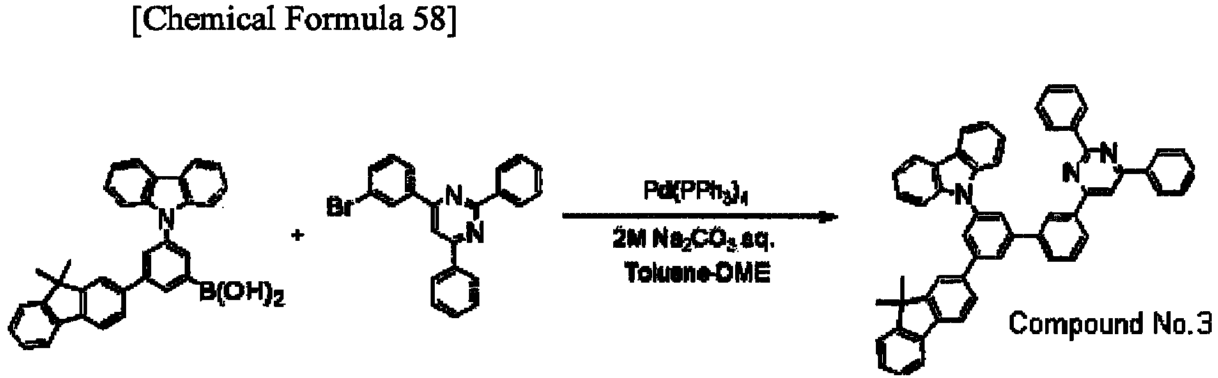
- Under an Ar gas atmosphere, the intermediate body X3 (4.8 g, 10 mmol), the intermediate body X6 (3.9 g, 10 mmol), an aqueous solution of 2M sodium carbonate (12 ml), toluene (20 ml), DME (20 ml) and Pd(PPh3)4 (0.35g) were stirred for 16 hours at a reflux temperature. After the reactant solution was cooled down to the room temperature, toluene (200 ml) and water (100 ml) were added thereto to separate an organic phase. The residue obtained by concentrating the organic phase was refined by silica-gel column chromatography (a developing solvent: hexane-toluene) and was recrystallized by toluene twice to provide a target object (a compound No. 3) as a white solid. A yield of the compound No. 3 was 3.2 g and a yield rate thereof was 43%.
FD mass analysis consequently showed that m/e was equal to 741 while a calculated molecular weight was 741, - Synthesis Example 4 (Synthesis of Compound No. 4)
-

- 4-bromobenzaldehyde (18.5 g, 100 mmol), acetophenone (12.0 g, 100 mmol), 1N-sodium methoxide/methanol solution (10 ml) and ethanol (200 ml) were stirred at room temperature for 5 hours at the room temperature under an Ar gas atmosphere. Subsequently, the reactant mixture was heated and stirred for another four hours at a reflux temperature. Next, benzamidine hydrochloride (9.4 g, 60 mmol) and sodium hydroxide (8.0 g, 200 mmol) were added thereto and stirred for five hours at 70 degrees C. After the reaction, the reactant mixture was filtered to separate an extract. The extract was refined by silica-gel column chromatography (a developing solvent: dichloromethane) to provide an intermediate body X7 as a white solid. A yield of the intermediate body X7 was 11.6 g and a yield rate thereof was 30%.
-

- Under an Ar gas atmosphere, the intermediate body X3 (4.8 g, 10 mmol), the intermediate body X7 (3.9 g, 10 mmol), an aqueous solution of 2M sodium carbonate (12 ml), toluene (20 ml), DME (20 ml) and Pd(PPh3)4 (0.35g) were stirred for 16 hours at a reflux temperature. After the reactant solution was cooled down to the room temperature, toluene (200 ml) and water (100 ml) were added thereto to separate an organic phase. The residue obtained by concentrating the organic phase was refined by silica-gel column chromatography (a developing solvent: hexane-toluene) and was recrystallized by toluene twice to provide a target object (a compound No. 4) as a white solid. A yield of the compound No. 4 was 2.6 g and a yield rate thereof was 35%.
FD mass analysis consequently showed that m/e was equal to 741 while a calculated molecular weight was 741. - Synthesis Example 5 (Synthesis of Compound No. 5)
-

- Under an Ar gas atmosphere, the intermediate body X5 (3.8 g, 10 mmol), 4-carbazolylphenyl boronic acid (2.9 g, 10 mmol), an aqueous solution of 2M sodium carbonate (12 ml), toluene (20 ml), DME (20 ml) and Pd(PPh3)4 (0.35g) were stirred for 20 hours at a reflux temperature. After the reactant solution was cooled down to the room temperature, toluene (200 ml) and water (100 ml) were added thereto to separate an organic phase. The residue obtained by concentrating the organic phase was refined by silica-gel column chromatography (a developing solvent: hexane-toluene) and was recrystallized by toluene twice to provide a target object (a compound No. 5) as a white solid. A yield of the compound No. 5 was 2.8 g and a yield rate thereof was 47%.
FD mass analysis consequently showed that m/e was equal to 589 while a calculated molecular weight was 589. - A glass substrate (size: 25 mm x 75 mm x 1.1 mm) having an ITO transparent electrode (manufactured by Geomatec Co., Ltd.) was ultrasonic-cleaned in isopropyl alcohol for five minutes, and then UV (Ultraviolet)/ozone-cleaned for 30 minutes.
After the glass substrate having the transparent electrode was cleaned, the glass substrate was mounted on a substrate holder of a vacuum deposition apparatus, and a hole injecting layer was initially formed by depositing a compound A onto the substrate to be 40 nm thick to cover a surface of the glass substrate where a transparent electrode line was provided. Next, a compound B was deposited onto the hole injecting layer to be 20 nm thick to provide a hole transporting layer.
On the hole transporting layer, the compound No. 1 as a phosphorescent host and Ir(Ph-ppy)3 as a phosphorescent dopant were co-evaporated (thickness: 40 nm), thereby providing a phosphorescent-emitting layer. The concentration of Ir(Ph-ppy)3 was 20 mass%.
On the phosphorescent-emitting layer, a 30-nm thick film of a compound C, a 1-nm thick film of LiF, an 80-nm thick film of a metal Al were laminated in sequence, thereby providing a cathode. LiF, which is an electron injectable electrode, was formed at a speed of 1 Å/min. -


- The organic EL devices each manufactured as described above were driven by direct-current electricity to emit light, so that luminance intensity and current density were measured to obtain voltage and luminous efficiency at a current density of 1 mA/cm2. Further, time elapsed until the initial luminance intensity of 20,000 cd/m2 was reduced to the half (i.e., time until half-life) was obtained. The results are shown in Table 1.
- The organic EL devices according respectively to Examples 2 to 5 were formed and evaluated in the same manner as in Example 1 except that the host compound No. 1 was replaced by host materials described in Table 1. The results of the evaluation are shown in Table 1,
-


- An organic EL device according to Comparative 1 was formed and evaluated in the same manner as in Example 1 except that the host compound No. 1 was replaced by a compound D (a host material described in
WO2003/0807 -

-
Table 1 Host compound voltage (V) @ 1mA/cm2 Luminous efficiency (cd/A) @ 1mA/cm2 Time until half-life (hrs) 20000 cd/m2 Example 1 No.1 3.2 86.7 350 Example 2 No.2 3.0 87.9 450 Example 3 No.3 3.6 88.3 500 Example 4 No.4 3.5 81.3 500 Example 5 No.5 3.1 74.4 300 Comparative 1 Compound D 4.7 51.1 300 - As seen from Table 1, the organic EL devices of Examples were emittable at low voltage and exhibited a high luminous efficiency as compared with the organic EL device of Comparative 1.
- A glass substrate (size: 25 mm x 75 mm x 1.1 mm) having an ITO transparent electrode (manufactured by Geomatec Co., Ltd.) was ultrasonic-cleaned in isopropyl alcohol for five minutes, and then UV (Ultraviolet)/ozone-cleaned for 30 minutes.
After the glass substrate having the transparent electrode was cleaned, the glass substrate was mounted on a substrate holder of a vacuum deposition apparatus, and a hole injecting layer was initially formed by depositing a compound A onto the substrate to be 40 nm thick to cover a surface of the glass substrate where a transparent electrode line was provided. Next, a compound B was deposited onto the hole injecting layer to be 20 nm thick to provide a hole transporting layer.
On the hole transporting layer, the compound D as a phosphorescent host and Ir(Ph-ppy)3 as a phosphorescent dopant were co-evaporated (thickness: 40 nm), thereby providing a phosphorescent-emitting layer. The concentration of Ir(Ph-ppy)3 was 20 mass%.
On the phosphorescent-emitting layer, a 5-nm thick film of the compound No.2, a 25-nm thick film of the compound C, a 1-nm thick film of LiF, an 80-nm thick film of a metal Al were laminated in sequence, thereby providing a cathode. LiF, which is an electron injectable electrode, was formed at a speed of 1 Å/min.
The results of the evaluation of the organic EL device are shown in Table 2. The comparative 1 shown in Table 2 as a comparative is the same as the comparative 1 above. -
Table 2 Host compound Electron transporting compound Voltage (V) @ 1mA/cm2 Luminous efficiency (cd/A) @ 1mA/cm2 Time untilhalf-life (hrs) 20000 cd/m2 Example 6 Compound D No. 2 4.7 52.5 400 Comparative 1 Compound D none 4.7 51.1 300 - As seen from Table 2, the compound of the invention was usable as an electron transporting compound and the organic EL devices of Examples had a longer lifetime than the organic EL device of the comparative.
- As described in detail, when the compounds of the invention are used as an organic-EL-device material, an organic EL device having a high luminous efficiency and being emittable at low voltage is obtainable. Accordingly, the organic EL device of the invention is significantly usable as a light source of various electronic devices and the like. Moreover, the compound of the invention is effectively usable as an organic-electron-device material for an organic solar cell, an organic semiconductor laser, a sensor using an organic substance and an organic TFT.
- The invention is applicable to a long-life organic EL device that exhibits a high luminous efficiency and is capable of being driven at low voltage required for power consumption saving as well as to an organic-EL-device material providing such an organic EL device.
-
- 1
- organic electroluminescence device
- 2
- substrate
- 3
- anode
- 4
- cathode
- 5
- phosphorescent-emitting layer
- 6
- hole injecting/transporting layer
- 7
- electron injecting/transporting layer
- 10
- organic thin-film layer
Claims (22)
- A fluorene-containing aromatic compound represented by a formula (1) below,

Ar represents a single bond, a substituted or unsubstituted aromatic ring having 5 to 40 ring carbon atoms;
Fl1 and Fl2 each independently represent a substituted or unsubstituted fluorenyl group;
p is an integer of 0 to 3 representing the number of a substituent(s) of -(L4-Fl1) directly bonding to Nr1;
when p is 2 or more, L4 is allowed to be the same or different and Fl1 is allowed to be the same or different;
q is an integer of 0 to 3 representing the number of a substituent(s) of -(L7-Fl2) directly bonding to Ar;
when q is 2 or more, L7 is allowed to be the same or different and Fl2 is allowed to be the same or different;
p+q=1 or more;
Cz1 and Cz2 each independently represent a substituted or unsubstituted carbazolyl group; m is an integer of 0 to 3 representing the number of a substituent(s) of -(L2-Cz1) directly bonding to Nr1;
when m is 2 or more, L2 is allowed to be the same or different and Cz1 is allowed to be the same or different;
n is an integer of 0 to 3 representing the number of a substituent(s) of -(L5-Cz2) directly bonding to Ar;
when n is 2 or more, L5 is allowed to be the same or different and Cz2 is allowed to be the same or different;
m+n=1 or more;
Y1 and Y2 each independently represent a hydrogen atom, a deuterium atom, a fluorine atom, a chlorine atom, a bromine atom, an iodine atom, a cyano group, a substituted or unsubstituted and linear, branched or cyclic alkyl group having 1 to 20 carbon atoms, a substituted or unsubstituted and linear, branched or cyclic alkoxy group having 1 to 20 carbon atoms, a substituted or unsubstituted and linear, branched or cyclic haloalkyl group having 1 to 20 carbon atoms, a substituted or unsubstituted and linear, branched or cyclic haloalkoxy group having 1 to 20 carbon atoms, a substituted or unsubstituted and linear, branched or cyclic alkylsilyl group having 1 to 10 carbon atoms, a substituted or unsubstituted arylsilyl group having 6 to 30 carbon atoms, a substituted or unsubstituted aryl group having 6 to 30 ring carbon atoms, or a substituted or unsubstituted heteroaryl group having 2 to 10 ring carbon atoms;
x is an integer of 1 to 3 representing the number of a substituent(s) of -(L3-Y1) directly bonding to Nr1;
when x is 2 or more, L3 is allowed to be the same or different and Y1 is allowed to be the same or different;
y is an integer of 1 to 3 representing the number of a substituent(s) of -(L6-Y2) directly bonding to Ar;
when y is 2 or more, L6 is allowed to be the same or different and Y2 is allowed to be the same or different;
m+p+x is less than or equal to a numeral represented by (the number of the possible substituent(s) for selected Nr1 minus 1);
n+q+y is less than or equal to a numeral represented by (the number of the possible substituent(s) for selected Ar minus 1); and
L1 to L7 each independently represent a single bond, a substituted or unsubstituted aromatic ring having 6 to 30 ring carbon atoms, or a substituted or unsubstituted aromatic heterocyclic ring having 2 to 30 ring carbon atoms; and k is an integer of 1 to 3, wherein
a compound represented by a formula (2) below is omitted from the fluorene-containing aromatic compound represented by the formula (1).
- The fluorene-containing aromatic compound according to claim 1, wherein
in the formula (1), Nr1 is a nitrogen-containing aromatic ring selected from a substituted or unsubstituted pyrrole ring, pyrazole ring, imidazole ring, triazole ring, pyridine ring, pyrimidine ring, pyridazine ring, pyrazine ring, triazine ring, indole ring, indazole ring, benzimidazole ring, quinoline ring, isoquinoline ring, cinnoline ring, quinoxaline ring and imidazopyridine ring. - The fluorene-containing aromatic compound according to claim 1 or 2, wherein each of Cz1 to Cz3 in the formula (1) is independently represented by a formula (3) or a formula (4) below,

f and g each independently represent an integer of 1 to 4,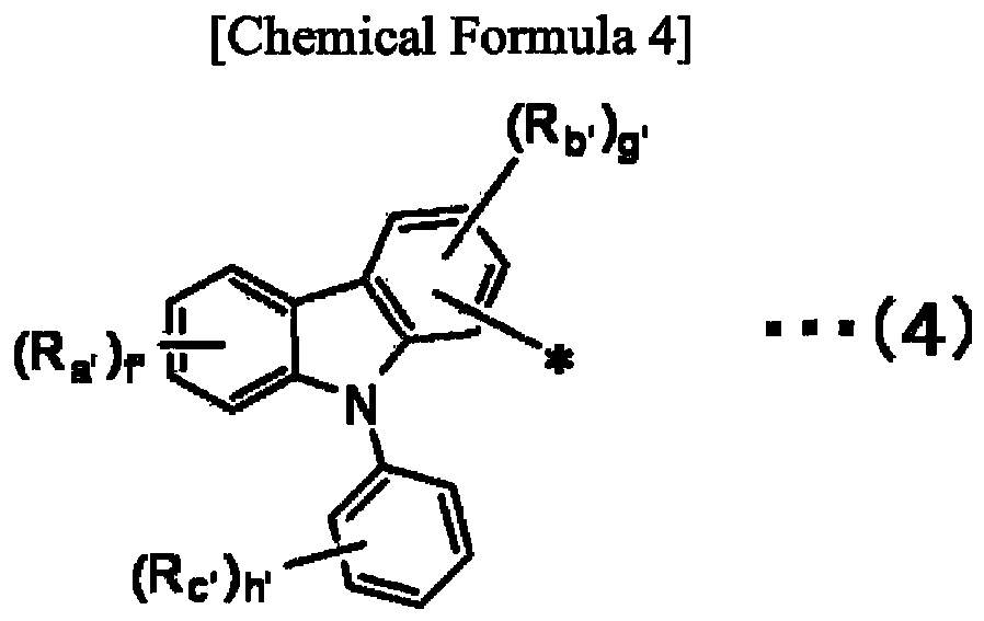
f' is an integer of 1 to 4;
g' is an integer of 1 to 3; and
h' is an integer of 1 to 5. - The fluorene-containing aromatic compound according to any one of claims 1 to 3, wherein k is 1 and m+n+p+q is less than or equal to 6 in the formula (1).
- The fluorene-containing aromatic compound according to any one of claims 1 to 4, wherein each of Y1 to Y2 in the formula (1) is independently a hydrogen atom or a phenyl group.
- The fluorene-containing aromatic compound according to any one of claims 1 to 5, wherein
k is 1;
L1, L2, L3, L5 and L6 each independently represent a single bond, a substituted or unsubstituted phenylene group, a substituted or unsubstituted biphenylene group, a substituted or unsubstituted terphenylene group, or a substituted or unsubstituted fluorenylene group; and
L4 and L7 each independently represent a single bond, a substituted or unsubstituted phenylene group, a substituted or unsubstituted biphenylene group, or a substituted or unsubstituted terphenylene group. - The fluorene-containing aromatic compound according to any one of claims 1 to 6, wherein m+n=1 or 2 and p+q=1 or 2 in the formula (1).
- The fluorene-containing aromatic compound according to any one of claims 1 to 7, wherein
in the formula (1), Ar represents a monocyclic aromatic ring selected from a substituted or unsubstituted benzene ring having 2 to 6 ring carbon atoms, pyrazole ring, imidazole ring, triazole ring, pyridine ring, pyrimidine ring, pyridazine ring, pyrazine ring, triazine ring and thiophene ring. - The fluorene-containing aromatic compound according to any one of claims 1 to 8, wherein Ar is a benzene ring in the formula (1).
- The fluorene-containing aromatic compound according to any one of claims 1 to 9, wherein each of Fl1 to Fl2 in the formula (1) is independently represented by a formula (5) below,

Y5, Y6, Y7, Y8 , Y9, Y10 and Y11 each independently represent: a hydrogen atom; a deuterium atom; a fluorine atom; a chlorine atom; a bromine atom; an iodine atom; a cyano group; a linear, branched or cyclic alkyl group having 1 to 10 carbon atoms; a linear, branched or cyclic alkoxy group having 1 to 10 carbon atoms; a linear, branched or cyclic haloalkyl group having 1 to 10 carbon atoms; a linear, branched or cyclic haloalkoxy group having 1 to 10 carbon atoms; a linear, branched or cyclic alkylsilyl group having 1 to 10 carbon atoms; a substituted or unsubstituted arylsilyl group having 6 to 30 carbon atoms; a substituted or unsubstituted aryl group having 6 to 30 ring carbon atoms; or a substituted or unsubstituted heteroaryl group having 2 to 10 ring carbon atoms. - The fluorene-containing aromatic compound according to claim 10, wherein
each of Y3 and Y4 is independently a linear alkyl group having 1 to 10 carbon atoms or a phenyl group in the formula (5). - The fluorene-containing aromatic compound according to claim 11, wherein both of Y3 and Y4 are a methyl group in the formula (5).
- The fluorene-containing aromatic compound according to any one of claims 1 to 12, wherein
each of Cz1 and Cz2 in the formula (1) is independently represented by a formula (3a) or a formula (4a) below.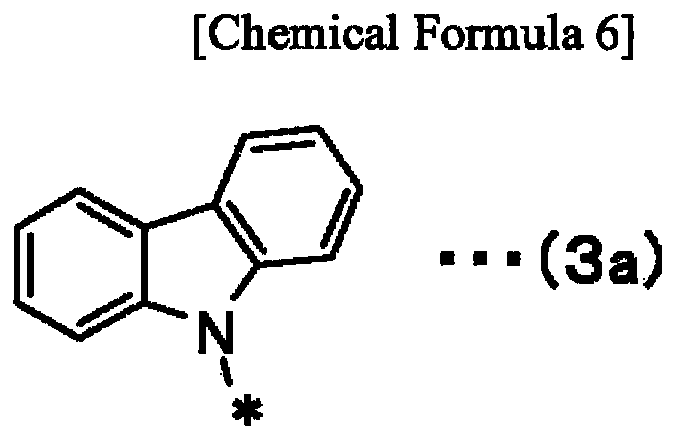

- The fluorene-containing aromatic compound according to any one of claims 1 to 13, wherein Nr1 is a pyrimidine ring in the formula (1).
- The fluorene-containing aromatic compound according to any one of claims 1 to 14, being used as an organic-electroluminescence-device material.
- An organic electroluminescence device comprising:a cathode;an anode; andan organic thin-film layer provided between the cathode and the anode, the organic thin-film layer formed of one or more layers comprising an emitting layer, whereinat least one layer of the organic thin-film layer comprises the fluorene-containing aromatic compound according to any one of claims 1 to 14.
- The organic electroluminescence device according to claim 16, wherein the emitting layer comprises the fluorene-containing aromatic compound as a host material.
- The organic electroluminescence device according to claim 16 or 17, wherein the emitting layer further comprises a phosphorescent material.
- The organic electroluminescence device according to claim 18, wherein the emitting layer comprises a host material and a phosphorescent material, the phosphorescent material being an ortho metalation of a complex of a metal atom selected from iridium (Ir), osmium (Os) and platinum (Pt).
- The organic electroluminescence device according to any one of claims 16 to 19, wherein the organic thin-film layer comprises an electron injecting layer provided between the cathode and the emitting layer, the electron injecting layer comprising a nitrogen-containing cyclic derivative.
- The organic electroluminescence device according to any one of claims 16 to 20, wherein the organic thin-film layer comprises an electron transporting layer provided between the cathode and the emitting layer, the electron transporting layer comprising the fluorene-containing aromatic compound.
- The organic electroluminescence device according to any one of claims 16 to 21, wherein a reduction-causing dopant is added in an interfacial region between the cathode and the organic thin-film layer.
Applications Claiming Priority (2)
| Application Number | Priority Date | Filing Date | Title |
|---|---|---|---|
| JP2009239786 | 2009-10-16 | ||
| PCT/JP2010/068079 WO2011046182A1 (en) | 2009-10-16 | 2010-10-14 | Fluorene-containing aromatic compound, material for organic electroluminescent element, and organic electroluminescent element using same |
Publications (2)
| Publication Number | Publication Date |
|---|---|
| EP2489664A1 true EP2489664A1 (en) | 2012-08-22 |
| EP2489664A4 EP2489664A4 (en) | 2013-04-03 |
Family
ID=43876231
Family Applications (1)
| Application Number | Title | Priority Date | Filing Date |
|---|---|---|---|
| EP10823450A Withdrawn EP2489664A4 (en) | 2009-10-16 | 2010-10-14 | AROMATIC COMPOUND CONTAINING FLUORENE, MATERIAL FOR ORGANIC ELECTROLUMINESCENCE ELEMENT, AND ORGANIC ELECTROLUMINESCENT ELEMENT USING SUCH MATERIAL |
Country Status (7)
| Country | Link |
|---|---|
| US (1) | US9266851B2 (en) |
| EP (1) | EP2489664A4 (en) |
| JP (1) | JPWO2011046182A1 (en) |
| KR (1) | KR20120052231A (en) |
| CN (1) | CN102471320A (en) |
| TW (1) | TW201118150A (en) |
| WO (1) | WO2011046182A1 (en) |
Cited By (4)
| Publication number | Priority date | Publication date | Assignee | Title |
|---|---|---|---|---|
| EP2468731A4 (en) * | 2009-08-21 | 2013-01-16 | Tosoh Corp | CYCLIC AZINE DERIVATIVES, METHODS FOR PRODUCING THE SAME, AND ORGANIC ELECTROLUMINESCENT ELEMENT CONTAINING THE SAME AS COMPONENT |
| WO2019115447A1 (en) * | 2017-12-15 | 2019-06-20 | Cynora Gmbh | Organic molecules with a trifluoromethyl-biphenyl core for use in optoelectronic devices |
| WO2019121341A1 (en) * | 2017-12-24 | 2019-06-27 | Cynora Gmbh | Organic molecules with a pyridine-phenyl core for use in optoelectronic devices |
| EP4299573A1 (en) * | 2022-06-30 | 2024-01-03 | Novaled GmbH | Compound, organic semiconducting material comprising the same, organic electronic device comprising the same and a method for preparing the organic electronic device |
Families Citing this family (29)
| Publication number | Priority date | Publication date | Assignee | Title |
|---|---|---|---|---|
| CN103270032B (en) | 2010-12-20 | 2016-05-04 | 出光兴产株式会社 | Aromatic heterocyclic derivative and organic electroluminescent element using same |
| TWI591059B (en) | 2011-08-25 | 2017-07-11 | 半導體能源研究所股份有限公司 | Light-emitting elements, light-emitting devices, electronic devices, lighting devices, and novel organic compounds |
| CN103380508B (en) | 2011-11-22 | 2017-09-08 | 出光兴产株式会社 | Aromatic heterocyclic derivative, material for organic electroluminescent element, and organic electroluminescent element |
| KR20130094903A (en) * | 2012-02-17 | 2013-08-27 | 롬엔드하스전자재료코리아유한회사 | Novel organic electroluminescent compounds |
| JP6007126B2 (en) | 2012-02-29 | 2016-10-12 | 株式会社半導体エネルギー研究所 | Fluorene compound, light emitting element, light emitting device, electronic device, and lighting device |
| US8969588B2 (en) * | 2012-06-05 | 2015-03-03 | Gilead Pharmasset Llc | Solid forms of an antiviral compound |
| JP6339071B2 (en) | 2012-07-23 | 2018-06-06 | メルク パテント ゲーエムベーハー | Materials for organic electroluminescent devices |
| JP6312960B2 (en) | 2012-08-03 | 2018-04-18 | 株式会社半導体エネルギー研究所 | Light emitting element, light emitting device, electronic device, lighting device, and heterocyclic compound |
| JP6335428B2 (en) * | 2012-12-21 | 2018-05-30 | 出光興産株式会社 | Organic electroluminescence device and electronic device |
| JP6317544B2 (en) | 2013-02-15 | 2018-04-25 | 出光興産株式会社 | Organic electroluminescence device and electronic device |
| KR20150115622A (en) * | 2014-04-04 | 2015-10-14 | 주식회사 엘지화학 | Hetero-cyclic compound and organic light emitting device comprising the same |
| KR101537500B1 (en) | 2014-04-04 | 2015-07-20 | 주식회사 엘지화학 | Organic light emitting diode |
| KR101537499B1 (en) * | 2014-04-04 | 2015-07-16 | 주식회사 엘지화학 | Organic light emitting diode |
| KR101542714B1 (en) * | 2014-04-04 | 2015-08-12 | 주식회사 엘지화학 | Hetero-cyclic compound and organic light emitting device comprising the same |
| EP3140302B1 (en) | 2014-05-05 | 2019-08-21 | Merck Patent GmbH | Materials for organic light emitting devices |
| KR102457008B1 (en) * | 2014-05-23 | 2022-10-19 | 가부시키가이샤 한도오따이 에네루기 켄큐쇼 | Heterocyclic compound, light-emitting element, light-emitting device, electronic device, and lighting device |
| KR102611317B1 (en) | 2014-12-24 | 2023-12-07 | 솔루스첨단소재 주식회사 | Organic compound and organic electro luminescence device comprising the same |
| CN108368088A (en) * | 2015-12-08 | 2018-08-03 | 喜星素材株式会社 | Heterocyclic compound and organic light emitting device using same |
| CN106967065A (en) * | 2017-03-30 | 2017-07-21 | 上海道亦化工科技有限公司 | Organic electroluminescent compounds and its luminescent device containing two carbazyl phenyl groups |
| US11778907B2 (en) | 2017-04-13 | 2023-10-03 | Merck Patent Gmbh | Composition for organic electronic devices |
| CN110785415A (en) | 2017-07-05 | 2020-02-11 | 默克专利有限公司 | Composition for organic electronic device |
| KR102653984B1 (en) | 2017-07-05 | 2024-04-02 | 메르크 파텐트 게엠베하 | Compositions for organic electronic devices |
| KR102360782B1 (en) * | 2017-07-20 | 2022-02-10 | 삼성디스플레이 주식회사 | Organic light emitting device |
| CN107216281A (en) * | 2017-07-24 | 2017-09-29 | 山东省科学院新材料研究所 | A kind of cyano-containing Two-photon fluorescent dye and its preparation method and application |
| TWI785142B (en) | 2017-11-14 | 2022-12-01 | 德商麥克專利有限公司 | Composition for organic electronic devices |
| CN111039991A (en) * | 2019-12-24 | 2020-04-21 | 吉林奥来德光电材料股份有限公司 | An organic phosphorescent material, preparation method and electroluminescent device comprising the same |
| JP7588355B2 (en) * | 2020-02-13 | 2024-11-22 | 株式会社KOALA Tech | Organic solid-state lasers, compounds and uses thereof |
| CN112442023B (en) | 2020-11-30 | 2021-08-24 | 长春海谱润斯科技股份有限公司 | Heterocyclic derivative and organic electroluminescent device thereof |
| CN112661714B (en) | 2020-12-22 | 2022-01-07 | 长春海谱润斯科技股份有限公司 | Heterocyclic compound and organic electroluminescent device containing same |
Family Cites Families (181)
| Publication number | Priority date | Publication date | Assignee | Title |
|---|---|---|---|---|
| BE558078A (en) | 1956-06-04 | |||
| LU35237A1 (en) | 1956-06-27 | |||
| NL242505A (en) | 1958-08-20 | |||
| NL250330A (en) | 1959-04-09 | |||
| JPS3716096B1 (en) | 1960-04-09 | 1962-10-09 | ||
| US3240597A (en) | 1961-08-21 | 1966-03-15 | Eastman Kodak Co | Photoconducting polymers for preparing electrophotographic materials |
| JPS3927577B1 (en) | 1962-01-29 | 1964-12-01 | ||
| US3180703A (en) | 1963-01-15 | 1965-04-27 | Kerr Mc Gee Oil Ind Inc | Recovery process |
| JPS45555B1 (en) | 1966-03-24 | 1970-01-09 | ||
| JPS463712B1 (en) | 1966-04-14 | 1971-01-29 | ||
| US3526501A (en) | 1967-02-03 | 1970-09-01 | Eastman Kodak Co | 4-diarylamino-substituted chalcone containing photoconductive compositions for use in electrophotography |
| US3542544A (en) | 1967-04-03 | 1970-11-24 | Eastman Kodak Co | Photoconductive elements containing organic photoconductors of the triarylalkane and tetraarylmethane types |
| US3658520A (en) | 1968-02-20 | 1972-04-25 | Eastman Kodak Co | Photoconductive elements containing as photoconductors triarylamines substituted by active hydrogen-containing groups |
| US3567450A (en) | 1968-02-20 | 1971-03-02 | Eastman Kodak Co | Photoconductive elements containing substituted triarylamine photoconductors |
| US3615404A (en) | 1968-04-25 | 1971-10-26 | Scott Paper Co | 1 3-phenylenediamine containing photoconductive materials |
| CA917980A (en) | 1969-06-20 | 1973-01-02 | J. Fox Charles | Alkylaminoaromatic organic photoconductors |
| BE756375A (en) | 1969-09-30 | 1971-03-01 | Eastman Kodak Co | NEW PHOTOCONDUCTIVE COMPOSITION AND PRODUCT CONTAINING IT FOR USE IN ELECTROPHOTOGRAPHY |
| BE756943A (en) | 1969-10-01 | 1971-03-16 | Eastman Kodak Co | NEW PHOTOCONDUCTIVE COMPOSITIONS AND PRODUCTS CONTAINING THEM, USED IN PARTICULAR IN ELECTROPHOTOGRAPHY |
| JPS4725336B1 (en) | 1969-11-26 | 1972-07-11 | ||
| JPS5110983B2 (en) | 1971-09-10 | 1976-04-08 | ||
| GB1413352A (en) | 1972-02-09 | 1975-11-12 | Scott Paper Co | Electrophotographic material |
| US3837851A (en) | 1973-01-15 | 1974-09-24 | Ibm | Photoconductor overcoated with triarylpyrazoline charge transport layer |
| GB1505409A (en) | 1974-12-20 | 1978-03-30 | Eastman Kodak Co | Photoconductive compositions |
| US4127412A (en) | 1975-12-09 | 1978-11-28 | Eastman Kodak Company | Photoconductive compositions and elements |
| US4012376A (en) | 1975-12-29 | 1977-03-15 | Eastman Kodak Company | Photosensitive colorant materials |
| CA1104866A (en) | 1976-08-23 | 1981-07-14 | Milan Stolka | Imaging member containing a substituted n,n,n',n',- tetraphenyl-[1,1'-biphenyl]-4,4'-diamine in the chargge transport layer |
| US4175961A (en) | 1976-12-22 | 1979-11-27 | Eastman Kodak Company | Multi-active photoconductive elements |
| US4123269A (en) | 1977-09-29 | 1978-10-31 | Xerox Corporation | Electrostatographic photosensitive device comprising hole injecting and hole transport layers |
| JPS5453435A (en) | 1977-10-01 | 1979-04-26 | Yoshikatsu Kume | Portable bicycle equipped with foldable type triangle frame |
| US4150987A (en) | 1977-10-17 | 1979-04-24 | International Business Machines Corporation | Hydrazone containing charge transport element and photoconductive process of using same |
| JPS5464299A (en) | 1977-10-29 | 1979-05-23 | Toshiba Corp | Beam deflector for charged particles |
| JPS54112637A (en) | 1978-02-06 | 1979-09-03 | Ricoh Co Ltd | Electrophotographic photoreceptor |
| JPS54110837A (en) | 1978-02-17 | 1979-08-30 | Ricoh Co Ltd | Electrophotographic photoreceptor |
| JPS54110536A (en) | 1978-02-20 | 1979-08-30 | Ichikoh Ind Ltd | Device for time-lag putting out room lamp for motorcar |
| JPS54119925A (en) | 1978-03-10 | 1979-09-18 | Ricoh Co Ltd | Photosensitive material for electrophotography |
| US4251612A (en) | 1978-05-12 | 1981-02-17 | Xerox Corporation | Dielectric overcoated photoresponsive imaging member |
| JPS6028342B2 (en) | 1978-06-21 | 1985-07-04 | コニカ株式会社 | electrophotographic photoreceptor |
| JPS6060052B2 (en) | 1978-07-21 | 1985-12-27 | コニカ株式会社 | electrophotographic photoreceptor |
| JPS5551086A (en) | 1978-09-04 | 1980-04-14 | Copyer Co Ltd | Novel pyrazoline compound, its preparation, and electrophotographic photosensitive substance comprising it |
| JPS5546760A (en) | 1978-09-29 | 1980-04-02 | Ricoh Co Ltd | Electrophotographic photoreceptor |
| JPS5552063A (en) | 1978-10-13 | 1980-04-16 | Ricoh Co Ltd | Electrophotographic receptor |
| JPS5552064A (en) | 1978-10-13 | 1980-04-16 | Ricoh Co Ltd | Electrophotographic receptor |
| JPS5574546A (en) | 1978-11-30 | 1980-06-05 | Ricoh Co Ltd | Electrophotographic photoreceptor |
| US4306008A (en) | 1978-12-04 | 1981-12-15 | Xerox Corporation | Imaging system with a diamine charge transport material in a polycarbonate resin |
| JPS5588064A (en) | 1978-12-05 | 1980-07-03 | Konishiroku Photo Ind Co Ltd | Electrophotographic receptor |
| JPS5588065A (en) | 1978-12-12 | 1980-07-03 | Konishiroku Photo Ind Co Ltd | Electrophotographic receptor |
| JPS5585495A (en) | 1978-12-18 | 1980-06-27 | Pacific Metals Co Ltd | Method of composting organic waste |
| JPS55108667A (en) | 1979-02-13 | 1980-08-21 | Ricoh Co Ltd | Electrophotographic receptor |
| US4233384A (en) | 1979-04-30 | 1980-11-11 | Xerox Corporation | Imaging system using novel charge transport layer |
| JPS6035058B2 (en) | 1979-05-17 | 1985-08-12 | 三菱製紙株式会社 | Organic photo-semiconductor electrophotographic materials |
| JPS564148A (en) | 1979-06-21 | 1981-01-17 | Konishiroku Photo Ind Co Ltd | Electrophotographic receptor |
| US4232103A (en) | 1979-08-27 | 1980-11-04 | Xerox Corporation | Phenyl benzotriazole stabilized photosensitive device |
| JPS5636656A (en) | 1979-09-03 | 1981-04-09 | Mitsubishi Paper Mills Ltd | Electrophotographic material |
| JPS5646234A (en) | 1979-09-21 | 1981-04-27 | Ricoh Co Ltd | Electrophotographic receptor |
| US4273846A (en) | 1979-11-23 | 1981-06-16 | Xerox Corporation | Imaging member having a charge transport layer of a terphenyl diamine and a polycarbonate resin |
| JPS5680051A (en) | 1979-12-04 | 1981-07-01 | Ricoh Co Ltd | Electrophotographic receptor |
| JPS5688141A (en) | 1979-12-20 | 1981-07-17 | Konishiroku Photo Ind Co Ltd | Electrophotographic receptor |
| JPS6034099B2 (en) | 1980-06-24 | 1985-08-07 | 富士写真フイルム株式会社 | electrophotographic photoreceptor |
| US4356429A (en) | 1980-07-17 | 1982-10-26 | Eastman Kodak Company | Organic electroluminescent cell |
| JPS6059590B2 (en) | 1980-09-03 | 1985-12-25 | 三菱製紙株式会社 | electrophotographic photoreceptor |
| JPS57148749A (en) | 1981-03-11 | 1982-09-14 | Fuji Photo Film Co Ltd | Electrophotographic receptor |
| JPS6093455A (en) | 1983-10-28 | 1985-05-25 | Fuji Xerox Co Ltd | Developer for electrophotography |
| JPS6094462A (en) | 1983-10-28 | 1985-05-27 | Ricoh Co Ltd | Stilbene derivatives and their production method |
| JPS60175052A (en) | 1984-02-21 | 1985-09-09 | Ricoh Co Ltd | Electrophotographic photoreceptor |
| JPS6114642A (en) | 1984-06-29 | 1986-01-22 | Konishiroku Photo Ind Co Ltd | Electrophotographic sensitive body |
| JPS6172255A (en) | 1984-09-14 | 1986-04-14 | Konishiroku Photo Ind Co Ltd | Electrophotographic sensitive body |
| US4665000A (en) | 1984-10-19 | 1987-05-12 | Xerox Corporation | Photoresponsive devices containing aromatic ether hole transport layers |
| JPS61210363A (en) | 1985-03-15 | 1986-09-18 | Canon Inc | electrophotographic photoreceptor |
| JPS61228451A (en) | 1985-04-03 | 1986-10-11 | Canon Inc | electrophotographic photoreceptor |
| US4588666A (en) | 1985-06-24 | 1986-05-13 | Xerox Corporation | Photoconductive imaging members with alkoxy amine charge transport molecules |
| JPS6210652A (en) | 1985-07-08 | 1987-01-19 | Minolta Camera Co Ltd | Photosensitive body |
| JPS6230255A (en) | 1985-07-31 | 1987-02-09 | Minolta Camera Co Ltd | Electrophotographic sensitive body |
| JPS6236674A (en) | 1985-08-05 | 1987-02-17 | Fuji Photo Film Co Ltd | Electrophotographic sensitive body |
| JPS6247646A (en) | 1985-08-27 | 1987-03-02 | Konishiroku Photo Ind Co Ltd | Photosensitive body |
| US4720432A (en) | 1987-02-11 | 1988-01-19 | Eastman Kodak Company | Electroluminescent device with organic luminescent medium |
| JPH01211399A (en) | 1988-02-19 | 1989-08-24 | Toshiba Corp | Dynamic shift register with scanning function |
| JPH02282263A (en) | 1988-12-09 | 1990-11-19 | Nippon Oil Co Ltd | Hole transferring material |
| JP2727620B2 (en) | 1989-02-01 | 1998-03-11 | 日本電気株式会社 | Organic thin film EL device |
| US4950950A (en) | 1989-05-18 | 1990-08-21 | Eastman Kodak Company | Electroluminescent device with silazane-containing luminescent zone |
| JPH02311591A (en) | 1989-05-25 | 1990-12-27 | Mitsubishi Kasei Corp | organic electroluminescent device |
| US5061569A (en) | 1990-07-26 | 1991-10-29 | Eastman Kodak Company | Electroluminescent device with organic electroluminescent medium |
| JP3016896B2 (en) | 1991-04-08 | 2000-03-06 | パイオニア株式会社 | Organic electroluminescence device |
| JP3704748B2 (en) | 1995-06-23 | 2005-10-12 | 東洋インキ製造株式会社 | Electron transport material for organic electroluminescence device and organic electroluminescence device using the same |
| TW306890B (en) | 1995-08-24 | 1997-06-01 | Tai Jin Mold Mfg Co Ltd | Positioning method for the grinding depth of a grinding machine |
| JP3924943B2 (en) | 1998-08-24 | 2007-06-06 | 東洋インキ製造株式会社 | Organic electroluminescent device material and organic electroluminescent device using the same |
| JP4320811B2 (en) | 1998-12-07 | 2009-08-26 | コニカミノルタホールディングス株式会社 | Organic electroluminescence device |
| JP2000173774A (en) | 1998-12-09 | 2000-06-23 | Sony Corp | Organic electroluminescent device |
| JP4105358B2 (en) | 2000-03-07 | 2008-06-25 | 富士フイルム株式会社 | Benzimidazole derivative, light emitting device material, and light emitting device |
| JP4116225B2 (en) | 1999-10-27 | 2008-07-09 | 富士フイルム株式会社 | Novel condensed heterocyclic compound, light emitting device material, and light emitting device using the same |
| JP3571977B2 (en) | 1999-11-12 | 2004-09-29 | キヤノン株式会社 | Organic light emitting device |
| KR100377321B1 (en) | 1999-12-31 | 2003-03-26 | 주식회사 엘지화학 | Electronic device comprising organic compound having p-type semiconducting characteristics |
| EP1453592B1 (en) | 2001-07-16 | 2009-12-23 | Miox Corporation | Dual head pump driven membrane system |
| JP5135657B2 (en) | 2001-08-01 | 2013-02-06 | コニカミノルタホールディングス株式会社 | Organic electroluminescence element and display device |
| US7990046B2 (en) | 2002-03-15 | 2011-08-02 | Idemitsu Kosan Co., Ltd. | Material for organic electroluminescent devices and organic electroluminescent devices made by using the same |
| JP4030093B2 (en) | 2002-03-22 | 2008-01-09 | 出光興産株式会社 | Material for organic electroluminescence device and organic electroluminescence device using the same |
| EP2169028B1 (en) | 2002-03-22 | 2018-11-21 | Idemitsu Kosan Co., Ltd. | Material for organic electroluminescent devices and organic electroluminescent devices made by using the same |
| JP4646494B2 (en) | 2002-04-11 | 2011-03-09 | 出光興産株式会社 | Novel nitrogen-containing heterocyclic derivative and organic electroluminescence device using the same |
| JP4036041B2 (en) | 2002-06-24 | 2008-01-23 | コニカミノルタホールディングス株式会社 | Organic electroluminescence element and display device |
| JP4261855B2 (en) | 2002-09-19 | 2009-04-30 | キヤノン株式会社 | Phenanthroline compound and organic light emitting device using the same |
| CN1703937B (en) | 2002-10-09 | 2010-11-24 | 出光兴产株式会社 | Organic electroluminescent device |
| EP1555305A4 (en) | 2002-10-21 | 2008-12-03 | Idemitsu Kosan Co | MATERIAL FOR ORGANIC ELECTROLUMINESCENCE ELEMENT AND ORGANIC ELECTROLUMINESCENT ELEMENT USING THE SAME |
| JP4963357B2 (en) | 2002-10-30 | 2012-06-27 | チバ ホールディング インコーポレーテッド | Electroluminescent device |
| JP4427947B2 (en) | 2002-11-18 | 2010-03-10 | コニカミノルタホールディングス株式会社 | Organic electroluminescence element and display device |
| EP2248870B1 (en) | 2002-11-26 | 2018-12-26 | Konica Minolta Holdings, Inc. | Organic electroluminscent element and display and illuminator |
| JP4265219B2 (en) | 2003-01-06 | 2009-05-20 | コニカミノルタホールディングス株式会社 | Organic electroluminescence element and display device |
| WO2004063159A1 (en) * | 2003-01-10 | 2004-07-29 | Idemitsu Kosan Co., Ltd. | Nitrogenous heterocyclic derivative and organic electroluminescent element employing the same |
| WO2004066685A1 (en) | 2003-01-24 | 2004-08-05 | Idemitsu Kosan Co., Ltd. | Organic electroluminescence device |
| KR20040072004A (en) * | 2003-02-07 | 2004-08-16 | 삼성에스디아이 주식회사 | Emitting compound for electroluminescence device and device using thereof |
| DE10356099A1 (en) | 2003-11-27 | 2005-07-07 | Covion Organic Semiconductors Gmbh | Organic electroluminescent element |
| US20060251918A1 (en) | 2003-12-11 | 2006-11-09 | Toshihiro Iwakuma | Organic electroluminescent device material and organic electroluminescent device using same |
| JP4408367B2 (en) | 2003-12-22 | 2010-02-03 | 富士フイルム株式会社 | Organic electroluminescence device |
| JPWO2005076668A1 (en) | 2004-02-06 | 2007-10-18 | 出光興産株式会社 | Organic electroluminescence device |
| TWI428053B (en) | 2004-02-09 | 2014-02-21 | Idemitsu Kosan Co | Organic electroluminescent element |
| TW200541401A (en) | 2004-02-13 | 2005-12-16 | Idemitsu Kosan Co | Organic electroluminescent device |
| US8895154B2 (en) | 2004-03-02 | 2014-11-25 | Idemitsu Kosan Co., Ltd. | Organic electroluminescent device |
| WO2005085387A1 (en) * | 2004-03-08 | 2005-09-15 | Idemitsu Kosan Co., Ltd. | Material for organic electroluminescence device and organic electroluminescence device utilizing the same |
| JP2005255561A (en) | 2004-03-09 | 2005-09-22 | Kyoto Univ | Polysubstituted pyrimidine and selective production method thereof |
| WO2005091684A1 (en) | 2004-03-19 | 2005-09-29 | Idemitsu Kosan Co., Ltd. | Organic electroluminescent device |
| JP4621201B2 (en) | 2004-03-25 | 2011-01-26 | 出光興産株式会社 | Organic electroluminescence device |
| JP4585786B2 (en) * | 2004-04-01 | 2010-11-24 | キヤノン株式会社 | Light emitting element and display device |
| KR101110890B1 (en) | 2004-04-02 | 2012-03-13 | 이데미쓰 고산 가부시키가이샤 | Organic electroluminescence element having two electroluminescent layers through electron barrier layer |
| US9523031B2 (en) | 2004-05-14 | 2016-12-20 | Idemitsu Kosan Co., Ltd. | Organic electroluminescent device |
| JP4541809B2 (en) | 2004-09-08 | 2010-09-08 | キヤノン株式会社 | Organic compound and organic light emitting device |
| JP2006131519A (en) * | 2004-11-04 | 2006-05-25 | Idemitsu Kosan Co Ltd | Fused ring-containing compound and organic electroluminescence device using the same |
| US7597967B2 (en) | 2004-12-17 | 2009-10-06 | Eastman Kodak Company | Phosphorescent OLEDs with exciton blocking layer |
| KR101420608B1 (en) | 2004-12-24 | 2014-07-18 | 미쓰비시 가가꾸 가부시키가이샤 | Organic compound, charge-transporting material, and organic electroluminescent element |
| WO2007029426A1 (en) | 2005-09-05 | 2007-03-15 | Idemitsu Kosan Co., Ltd. | Blue light emitting organic electroluminescence element |
| JPWO2007029402A1 (en) | 2005-09-08 | 2009-03-12 | 出光興産株式会社 | Organic electroluminescence device |
| JPWO2007029806A1 (en) | 2005-09-09 | 2009-03-19 | 出光興産株式会社 | Azaaromatic compound having azafluoranthene skeleton and organic electroluminescence device using the same |
| US7651791B2 (en) | 2005-12-15 | 2010-01-26 | Idemitsu Kosan Co., Ltd. | Material for organic electroluminescence device and electroluminescence device employing the same |
| WO2007069569A1 (en) | 2005-12-15 | 2007-06-21 | Idemitsu Kosan Co., Ltd. | Organic electroluminescence element material and organic electroluminescence element using same |
| JP4864476B2 (en) | 2006-02-14 | 2012-02-01 | 出光興産株式会社 | Organic electroluminescence device |
| JP2007261969A (en) | 2006-03-28 | 2007-10-11 | Canon Inc | 2,6-Fluorenyl-substituted pyridine compound and organic light-emitting device using the same |
| EP2034538B1 (en) | 2006-06-02 | 2013-10-09 | Idemitsu Kosan Co., Ltd. | Material for organic electroluminescence element, and organic electroluminescence element using the material |
| KR20090051163A (en) | 2006-08-04 | 2009-05-21 | 이데미쓰 고산 가부시키가이샤 | Organic electroluminescent element |
| WO2010131855A2 (en) | 2009-05-13 | 2010-11-18 | 덕산하이메탈(주) | Compound containing a 5-membered heterocycle and organic light-emitting diode using same, and terminal for same |
| JP2008147426A (en) | 2006-12-11 | 2008-06-26 | Idemitsu Kosan Co Ltd | Organic electroluminescence device |
| JP2008147424A (en) | 2006-12-11 | 2008-06-26 | Idemitsu Kosan Co Ltd | Organic electroluminescence device |
| EP2133932A4 (en) | 2007-03-23 | 2011-06-22 | Idemitsu Kosan Co | ORGANIC ELECTROLUMINESCENCE DEVICE |
| US8399108B2 (en) * | 2007-05-28 | 2013-03-19 | Cheil Industries, Inc. | Material for organic electro-optical device having fluorene derivative compound and organic electro-optical device including the same |
| WO2009008205A1 (en) | 2007-07-07 | 2009-01-15 | Idemitsu Kosan Co., Ltd. | Organic electroluminescent device and material for organic electroluminescent device |
| JP2009016693A (en) | 2007-07-07 | 2009-01-22 | Idemitsu Kosan Co Ltd | Host material and organic EL element |
| TW200920813A (en) | 2007-07-07 | 2009-05-16 | Idemitsu Kosan Co | Organic electroluminescence device |
| WO2009008311A1 (en) | 2007-07-07 | 2009-01-15 | Idemitsu Kosan Co., Ltd. | Chrysene derivative and organic electroluminescent device using the same |
| TW200920178A (en) | 2007-07-07 | 2009-05-01 | Idemitsu Kosan Co | Organic electroluminescence device and organic electroluminescence material containing solution |
| JP5194596B2 (en) | 2007-07-11 | 2013-05-08 | コニカミノルタホールディングス株式会社 | Organic electroluminescence element, display device and lighting device |
| US20090102363A1 (en) | 2007-08-03 | 2009-04-23 | Idemitsu Kosan Co., Ltd. | Metal complex compound, material for organic electroluminescence device and organic electroluminescence device using the same |
| KR20090024998A (en) | 2007-09-05 | 2009-03-10 | 제일모직주식회사 | Organic photoelectric device material including bipolar organic compound having hole transporter and electron transporter in a molecule and organic photoelectric device using the same |
| KR101002733B1 (en) | 2007-09-14 | 2010-12-21 | 제일모직주식회사 | Organic compound, and organic photoelectric device comprising the same |
| JP5478818B2 (en) | 2007-09-18 | 2014-04-23 | ユー・ディー・シー アイルランド リミテッド | Organic electroluminescence device |
| EP2202818B1 (en) | 2007-09-28 | 2014-11-12 | Idemitsu Kosan Co., Ltd. | Organic el device |
| JP5249654B2 (en) | 2007-11-28 | 2013-07-31 | 出光興産株式会社 | Organic electroluminescence device using fluoranthene derivative |
| JP5525702B2 (en) | 2007-11-28 | 2014-06-18 | 出光興産株式会社 | Organic electroluminescence device using indenoperylene derivative |
| JP5317470B2 (en) | 2007-12-27 | 2013-10-16 | 出光興産株式会社 | Material for organic electroluminescence device and organic electroluminescence device using the same |
| JP5325484B2 (en) | 2008-02-15 | 2013-10-23 | 出光興産株式会社 | Organic electroluminescence device |
| WO2009104733A1 (en) * | 2008-02-22 | 2009-08-27 | 東洋インキ製造株式会社 | Organic electroluminescent device material and organic electroluminescent device |
| JP4830127B2 (en) | 2008-03-22 | 2011-12-07 | コニカミノルタホールディングス株式会社 | Organic electroluminescence element and display device |
| EP2460866B1 (en) | 2008-05-13 | 2019-12-11 | Konica Minolta Holdings, Inc. | Organic electroluminescent element, display device and lighting device |
| US8057919B2 (en) | 2008-06-05 | 2011-11-15 | Idemitsu Kosan Co., Ltd. | Material for organic electroluminescence device and organic electroluminescence device using the same |
| US8049411B2 (en) | 2008-06-05 | 2011-11-01 | Idemitsu Kosan Co., Ltd. | Material for organic electroluminescence device and organic electroluminescence device using the same |
| KR20090131958A (en) | 2008-06-19 | 2009-12-30 | 제일모직주식회사 | Compound for organic photoelectric device and organic photoelectric device including same |
| EP2141214A3 (en) | 2008-06-25 | 2010-02-24 | Gracel Display Inc. | Novel organic electroluminescent compounds and organic electroluminescent device using the same |
| KR100958641B1 (en) | 2008-08-18 | 2010-05-20 | 삼성모바일디스플레이주식회사 | Organic light emitting device having a light efficiency improving layer |
| WO2010044342A1 (en) | 2008-10-15 | 2010-04-22 | コニカミノルタホールディングス株式会社 | Organic el element, organic el element manufacturing method, white organic el element, display device, and illumination device |
| KR101506919B1 (en) | 2008-10-31 | 2015-03-30 | 롬엔드하스전자재료코리아유한회사 | Novel compounds for organic electronic material and organic electronic device using the same |
| KR101288557B1 (en) | 2008-12-24 | 2013-07-22 | 제일모직주식회사 | Novel compound for organic photoelectric device and organic photoelectric device including the same |
| CN102292327A (en) * | 2009-01-22 | 2011-12-21 | 保土谷化学工业株式会社 | Compound having triazole ring structure connected with pyridyl group and organic electroluminescent device |
| JP2010185047A (en) | 2009-02-13 | 2010-08-26 | Mitsubishi Chemicals Corp | Composition for organic electroluminescent element, organic thin film, organic electroluminescent element, organic el display device, and organic el illumination |
| JP5544103B2 (en) | 2009-03-04 | 2014-07-09 | 出光興産株式会社 | Aromatic compound, material for organic electronic device, and organic electroluminescence device using the same |
| KR101603070B1 (en) | 2009-03-31 | 2016-03-14 | 롬엔드하스전자재료코리아유한회사 | Novel organic electroluminescent compounds and organic electroluminescent device using the same |
| KR101477613B1 (en) | 2009-03-31 | 2014-12-30 | 롬엔드하스전자재료코리아유한회사 | Novel compounds for organic electronic materials and organic electronic devices containing them |
| KR101172052B1 (en) | 2009-05-08 | 2012-08-07 | 덕산하이메탈(주) | Compound and Organic Electronic Element Using the Same, and Terminal Thereof |
| KR101311934B1 (en) | 2009-06-08 | 2013-09-26 | 제일모직주식회사 | Composition for organic photoelectric device and organic photoelectric device using the same |
| US8461574B2 (en) | 2009-06-12 | 2013-06-11 | Idemitsu Kosan Co., Ltd. | Organic electroluminescence device |
| US20100314644A1 (en) | 2009-06-12 | 2010-12-16 | Idemitsu Kosan Co., Ltd. | Organic electroluminescent device |
| JP5735229B2 (en) | 2009-07-31 | 2015-06-17 | ユー・ディー・シー アイルランド リミテッド | Organic electroluminescence device |
| JP4474493B1 (en) | 2009-07-31 | 2010-06-02 | 富士フイルム株式会社 | Organic electroluminescence device |
| JP4590020B1 (en) | 2009-07-31 | 2010-12-01 | 富士フイルム株式会社 | Charge transport material and organic electroluminescent device |
| EP2461390B1 (en) | 2009-07-31 | 2018-05-23 | UDC Ireland Limited | Organic electroluminescent element |
| JP4523992B1 (en) | 2009-07-31 | 2010-08-11 | 富士フイルム株式会社 | Organic electroluminescence device |
| WO2011037429A2 (en) | 2009-09-28 | 2011-03-31 | 덕산하이메탈(주) | Compounds having 5-membered aryl-ring-condensed heterocyclic derivatives, organic electronic device using the compounds, and terminal comprising the organic electronic device |
-
2010
- 2010-10-14 CN CN2010800338130A patent/CN102471320A/en active Pending
- 2010-10-14 EP EP10823450A patent/EP2489664A4/en not_active Withdrawn
- 2010-10-14 US US13/386,240 patent/US9266851B2/en active Active
- 2010-10-14 WO PCT/JP2010/068079 patent/WO2011046182A1/en not_active Ceased
- 2010-10-14 JP JP2011536177A patent/JPWO2011046182A1/en not_active Withdrawn
- 2010-10-14 KR KR1020127001254A patent/KR20120052231A/en not_active Ceased
- 2010-10-15 TW TW099135274A patent/TW201118150A/en unknown
Cited By (6)
| Publication number | Priority date | Publication date | Assignee | Title |
|---|---|---|---|---|
| EP2468731A4 (en) * | 2009-08-21 | 2013-01-16 | Tosoh Corp | CYCLIC AZINE DERIVATIVES, METHODS FOR PRODUCING THE SAME, AND ORGANIC ELECTROLUMINESCENT ELEMENT CONTAINING THE SAME AS COMPONENT |
| WO2019115447A1 (en) * | 2017-12-15 | 2019-06-20 | Cynora Gmbh | Organic molecules with a trifluoromethyl-biphenyl core for use in optoelectronic devices |
| EP4692276A3 (en) * | 2017-12-15 | 2026-04-08 | Samsung Display Co., Ltd. | Organic molecules with a trifluoromethyl-biphenyl core for use in optoelectronic devices |
| WO2019121341A1 (en) * | 2017-12-24 | 2019-06-27 | Cynora Gmbh | Organic molecules with a pyridine-phenyl core for use in optoelectronic devices |
| EP4299573A1 (en) * | 2022-06-30 | 2024-01-03 | Novaled GmbH | Compound, organic semiconducting material comprising the same, organic electronic device comprising the same and a method for preparing the organic electronic device |
| WO2024002883A1 (en) * | 2022-06-30 | 2024-01-04 | Novaled Gmbh | Compound, organic semiconducting material comprising the same, organic electronic device comprising the same and a method for preparing the organic electronic device |
Also Published As
| Publication number | Publication date |
|---|---|
| CN102471320A (en) | 2012-05-23 |
| WO2011046182A1 (en) | 2011-04-21 |
| US20120126217A1 (en) | 2012-05-24 |
| TW201118150A (en) | 2011-06-01 |
| KR20120052231A (en) | 2012-05-23 |
| JPWO2011046182A1 (en) | 2013-03-07 |
| EP2489664A4 (en) | 2013-04-03 |
| US9266851B2 (en) | 2016-02-23 |
Similar Documents
| Publication | Publication Date | Title |
|---|---|---|
| US9266851B2 (en) | Fluorene-containing aromatic compound, material for organic electroluminescent element, and organic electroluminescent element using same | |
| EP3010055B1 (en) | Material for organic electroluminescent elements, organic electroluminescent element using same, and electronic device | |
| KR101720444B1 (en) | Biscarbazole derivative and organic electroluminescent element using same | |
| JP5870045B2 (en) | Biscarbazole derivative and organic electroluminescence device using the same | |
| KR102232993B1 (en) | Organic electroluminescence element | |
| JP6195828B2 (en) | Material for organic electroluminescence device and organic electroluminescence device using the same | |
| JP6270735B2 (en) | Aromatic amine derivative and organic electroluminescence device | |
| KR101916594B1 (en) | Polycyclic compound and organic light emitting device comprising the same | |
| JP6114232B2 (en) | Heterocyclic compound, material for organic electroluminescence device using the same, and organic electroluminescence device and electronic equipment using the same | |
| EP2540707A1 (en) | Substituted pyridyl compound and organic electroluminescent element | |
| EP2757101A1 (en) | Fused heterocyclic aromatic derivative, organic electroluminescence element material, and organic electroluminescence element using same | |
| EP2544257A1 (en) | Material for organic electroluminescent element, and organic electroluminescent element using same | |
| WO2014157708A1 (en) | Heterocyclic compound, material for organic electroluminescent elements using same, organic electroluminescent element using same, and electronic device | |
| EP3040335B1 (en) | Compound, organic electroluminescent element, and electronic device | |
| TWI627172B (en) | Novel pyrimidine derivatives and organic electroluminescent elements | |
| US20140034935A1 (en) | Compound having substituted ortho-terphenyl structure, and organic electroluminescent device |
Legal Events
| Date | Code | Title | Description |
|---|---|---|---|
| PUAI | Public reference made under article 153(3) epc to a published international application that has entered the european phase |
Free format text: ORIGINAL CODE: 0009012 |
|
| 17P | Request for examination filed |
Effective date: 20120113 |
|
| AK | Designated contracting states |
Kind code of ref document: A1 Designated state(s): AL AT BE BG CH CY CZ DE DK EE ES FI FR GB GR HR HU IE IS IT LI LT LU LV MC MK MT NL NO PL PT RO RS SE SI SK SM TR |
|
| DAX | Request for extension of the european patent (deleted) | ||
| A4 | Supplementary search report drawn up and despatched |
Effective date: 20130301 |
|
| RIC1 | Information provided on ipc code assigned before grant |
Ipc: H01L 51/50 20060101ALI20130225BHEP Ipc: C07D 403/14 20060101ALI20130225BHEP Ipc: C07D 403/10 20060101AFI20130225BHEP Ipc: C09K 11/06 20060101ALI20130225BHEP Ipc: H05B 33/14 20060101ALI20130225BHEP |
|
| STAA | Information on the status of an ep patent application or granted ep patent |
Free format text: STATUS: THE APPLICATION HAS BEEN WITHDRAWN |
|
| 18W | Application withdrawn |
Effective date: 20131230 |