EP2489618A2 - Spulenfixiervorrichtung - Google Patents
Spulenfixiervorrichtung Download PDFInfo
- Publication number
- EP2489618A2 EP2489618A2 EP11160328A EP11160328A EP2489618A2 EP 2489618 A2 EP2489618 A2 EP 2489618A2 EP 11160328 A EP11160328 A EP 11160328A EP 11160328 A EP11160328 A EP 11160328A EP 2489618 A2 EP2489618 A2 EP 2489618A2
- Authority
- EP
- European Patent Office
- Prior art keywords
- bobbin
- rotating shaft
- fixing
- rotating
- shaft
- Prior art date
- Legal status (The legal status is an assumption and is not a legal conclusion. Google has not performed a legal analysis and makes no representation as to the accuracy of the status listed.)
- Granted
Links
Images


Classifications
-
- B—PERFORMING OPERATIONS; TRANSPORTING
- B65—CONVEYING; PACKING; STORING; HANDLING THIN OR FILAMENTARY MATERIAL
- B65H—HANDLING THIN OR FILAMENTARY MATERIAL, e.g. SHEETS, WEBS, CABLES
- B65H16/00—Unwinding, paying-out webs
- B65H16/02—Supporting web roll
- B65H16/04—Supporting web roll cantilever type
-
- B—PERFORMING OPERATIONS; TRANSPORTING
- B65—CONVEYING; PACKING; STORING; HANDLING THIN OR FILAMENTARY MATERIAL
- B65H—HANDLING THIN OR FILAMENTARY MATERIAL, e.g. SHEETS, WEBS, CABLES
- B65H18/00—Winding webs
- B65H18/02—Supporting web roll
- B65H18/026—Cantilever type
-
- B—PERFORMING OPERATIONS; TRANSPORTING
- B65—CONVEYING; PACKING; STORING; HANDLING THIN OR FILAMENTARY MATERIAL
- B65H—HANDLING THIN OR FILAMENTARY MATERIAL, e.g. SHEETS, WEBS, CABLES
- B65H49/00—Unwinding or paying-out filamentary material; Supporting, storing or transporting packages from which filamentary material is to be withdrawn or paid-out
- B65H49/36—Securing packages to supporting devices
-
- B—PERFORMING OPERATIONS; TRANSPORTING
- B65—CONVEYING; PACKING; STORING; HANDLING THIN OR FILAMENTARY MATERIAL
- B65H—HANDLING THIN OR FILAMENTARY MATERIAL, e.g. SHEETS, WEBS, CABLES
- B65H75/00—Storing webs, tapes, or filamentary material, e.g. on reels
- B65H75/02—Cores, formers, supports, or holders for coiled, wound, or folded material, e.g. reels, spindles, bobbins, cop tubes, cans, mandrels or chucks
- B65H75/18—Constructional details
- B65H75/24—Constructional details adjustable in configuration, e.g. expansible
- B65H75/242—Expansible spindles, mandrels or chucks, e.g. for securing or releasing cores, holders or packages
- B65H75/245—Expansible spindles, mandrels or chucks, e.g. for securing or releasing cores, holders or packages by deformation of an elastic or flexible material
-
- B—PERFORMING OPERATIONS; TRANSPORTING
- B65—CONVEYING; PACKING; STORING; HANDLING THIN OR FILAMENTARY MATERIAL
- B65H—HANDLING THIN OR FILAMENTARY MATERIAL, e.g. SHEETS, WEBS, CABLES
- B65H75/00—Storing webs, tapes, or filamentary material, e.g. on reels
- B65H75/02—Cores, formers, supports, or holders for coiled, wound, or folded material, e.g. reels, spindles, bobbins, cop tubes, cans, mandrels or chucks
- B65H75/18—Constructional details
- B65H75/28—Arrangements for positively securing ends of material
-
- B—PERFORMING OPERATIONS; TRANSPORTING
- B65—CONVEYING; PACKING; STORING; HANDLING THIN OR FILAMENTARY MATERIAL
- B65H—HANDLING THIN OR FILAMENTARY MATERIAL, e.g. SHEETS, WEBS, CABLES
- B65H2301/00—Handling processes for sheets or webs
- B65H2301/40—Type of handling process
- B65H2301/41—Winding, unwinding
- B65H2301/413—Supporting web roll
- B65H2301/4132—Cantilever arrangement
- B65H2301/41324—Cantilever arrangement linear movement of roll support
- B65H2301/4133—Cantilever arrangement linear movement of roll support special features
- B65H2301/41335—Cantilever arrangement linear movement of roll support special features locking mechanism for roll, e.g. axial flange
-
- B—PERFORMING OPERATIONS; TRANSPORTING
- B65—CONVEYING; PACKING; STORING; HANDLING THIN OR FILAMENTARY MATERIAL
- B65H—HANDLING THIN OR FILAMENTARY MATERIAL, e.g. SHEETS, WEBS, CABLES
- B65H2402/00—Constructional details of the handling apparatus
- B65H2402/60—Coupling, adapter or locking means
-
- B—PERFORMING OPERATIONS; TRANSPORTING
- B65—CONVEYING; PACKING; STORING; HANDLING THIN OR FILAMENTARY MATERIAL
- B65H—HANDLING THIN OR FILAMENTARY MATERIAL, e.g. SHEETS, WEBS, CABLES
- B65H2701/00—Handled material; Storage means
- B65H2701/50—Storage means for webs, tapes, or filamentary material
- B65H2701/52—Integration of elements inside the core or reel
- B65H2701/526—Magnets
Definitions
- the present invention relates to a bobbin fixing apparatus, and more particularly, to a bobbin fixing apparatus in which a bobbin is placed on a rotating shaft to ensure simplified coupling/separation and normal rotation thereof regardless of a direction in which the bobbin is placed on the rotating shaft, and an end of an object to be wound on or unwound from the bobbin can be kept in a fixed position or released from the fixed position when the bobbin is placed on the rotating shaft, resulting in increased fixing convenience.
- a bobbin is a device around which an extremely long slender object is wound for storage or unwound for use.
- the bobbin is secured to a rotating shaft such that the object is wound on or unwound from the bobbin via rotation of the bobbin.
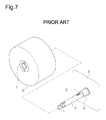
- a conventional bobbin fixing apparatus includes a rotating shaft 2 rotatably installed to a mounting plate 5 such that a bobbin B is placed on the rotating shaft 2.
- the conventional bobbin fixing apparatus is provided at an end of the rotating shaft 2 with a detent 1 to prevent separation of the bobbin B placed on the rotating shaft 2.
- the detent 1 is adapted to be rotated when the bobbin B is placed on the rotating shaft 2.
- an elastic spring (not shown) and a horizontally movable stopper (not shown) are accommodated in the rotating shaft 2, and a lower end of a hinge 3 is connected to a central position of the rotating shaft 2.
- a detent insertion recess 7 is indented in an outer surface of the bobbin B.
- a part of the detent 1 is inserted into the detent insertion recess 7 to allow the bobbin B to be secured to the rotating shaft 2.
- the hinge 3 comes into contact with an inner surface of the bobbin B and is pushed into the rotating shaft 2 upon receiving pressure applied by the bobbin B.
- the stopper and the elastic spring assist in pushing the hinge 3 into the rotating shaft 2, thereby causing the detent 1 to be rotated and inserted into the detent insertion recess 7 in linkage with movement of the hinge 3.
- the bobbin B is secured to the rotating shaft 2.
- a coupling member 9a by which an end of an object to be wound is caught, is installed on the bobbin B.
- a rotatable member 9b is rotatably seated on an upper surface of the coupling member 9a using an elastic torsion member (not shown) to keep the end of the object in a fixed position.
- the detent 1 may fail to accurately secure the incorrectly positioned bobbin B.
- the bobbin B may be unintentionally separated from the rotating shaft 2 during rotation of the rotating shaft 2, which may stop a current operation and cause damage to a device, to which the bobbin B is installed, or damage to an object wound on the bobbin B.
- the present invention has been made in view of the above problems, and it is an object of the present invention to provide a bobbin fixing apparatus in which a bobbin is simply placed on and is secured to a rotating shaft.
- a bobbin fixing apparatus including a mounting plate, a rotating shaft installed to a front surface of the mounting plate and provided with a fixing unit partially protruding from the rotating shaft so as to be inserted into the rotating shaft, and a bobbin on or from which an object is wound or unwound, the bobbin being placed on the rotating shaft regardless of a direction in which the bobbin accesses the rotating shaft such that the fixing unit is exposed in front of the bobbin.
- the fixing unit may include a recess indented in a front circumferential position of the rotating shaft, and a shaft fixing member inserted in the recess so as to partially protrude from the rotating shaft, the shaft fixing member being completely inserted into the recess while pressing an elastic member provided therebelow upon receiving pressure applied when the bobbin is placed on the rotating shaft.
- a through-hole may be perforated in the shaft fixing member to guide the shaft fixing member to be inserted into the recess and be installed within the rotating shaft, and a penetrating member may be inserted in the through-hole such that both ends thereof are accommodated within the shaft fixing member.
- the bobbin may include a rotating body consisting of a first rotating body and a second rotating body spaced apart from each other, the first and second rotating bodies respectively having shaft holes for insertion of the rotating shaft, a plurality of bobbin members, on which the object is wound, each bobbin member having one end and the other end respectively connected to the first and second rotating bodies to guide insertion of the rotating shaft into the rotating body, and an end coupler having one end and the other end respectively connected to the first and second rotating bodies to guide insertion of the rotating shaft into the rotating body, the end coupler serving to keep an end of the object in a fixed position or release the end of the object from the fixed position upon receiving pressure applied when the rotating body is placed on the rotating shaft.
- the end coupler may include a first coupling member in which a moving pressure member centrally provided with a first magnet is installed, the moving pressure member being configured such that both ends thereof protrude outward from the first and second rotating bodies and being movable toward the first rotating body or the second rotating body, and a second coupling member spaced apart from the first coupling member and internally provided with a second magnet at a position corresponding to the first magnet, both ends of the second coupling member being installed in vertically elongated holes of the first and second rotating bodies so as to be moved toward or away from the first coupling member.
- the first magnet and the second magnet may be oppositely charged magnets.
- Third magnets may be provided at opposite sides of the first magnet such that a distance between the center of the first magnet and the center of either of the third magnets is equal to a moved distance of the moving pressure member when pressure is applied to the moving pressure member, the third magnets and the second magnet being magnets of like magnetic polarity.
- a central portion of the moving pressure member may have a greater outer diameter than an outer diameter of both end portions of the moving pressure member.
- An elastic member may be wound on either of the end portions of the moving pressure member to return the moving pressure member to an original position thereof when pressure applied to move the moving pressure member is removed.
- the end coupler may further include a pressure ring separably placed on the rotating shaft to press one end of the movable pressure member when the rotating body is placed on the rotating shaft.
- a fixing recess may be formed in an outer surface of the bobbin such that one end of the shaft fixing member of the fixing unit is inserted into the fixing recess when the bobbin is placed on the rotating shaft.
- FIG. 1 is a view illustrating a bobbin and a rotating shaft provided in a bobbin fixing apparatus according to the present invention
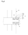
- FIG. 2 is a view illustrating the bobbin placed on the rotating shaft of the bobbin fixing apparatus according to the present invention
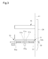
- FIG. 3 is a view illustrating an end coupler provided in the bobbin fixing apparatus according to the present invention.
- the bobbin fixing apparatus of the present invention includes a mounting plate 10, a rotating shaft 30 mounted to a front surface of the mounting plate 10 and provided with a fixing unit 20 partially protruding from the rotating shaft 30 so as to be inserted into the rotating shaft 30, and a bobbin 40 on which an object is wound, the bobbin 40 being placed on the rotating shaft 30 regardless of a direction in which the bobbin 40 accesses the rotating shaft 30 such that the fixing unit 20 is exposed in front of the bobbin 40.
- the mounting plate 10 may be one surface of a device to which the bobbin 40 which will be described in detail hereinafter is installed.
- the front surface of the mounting plate 10 is provided with a rotating shaft mounting hole 11 into which the rotating shaft 30 which will be described in detail hereinafter is inserted, which enables rotatable installation of the rotating shaft 30.
- the rotating shaft 30 is installed to the front surface of the mounting plate 10 such that the bobbin 40 which will be described in detail hereinafter is rotatably placed on the rotating shaft 30 such that the object is wound on or unwound from the bobbin 40 via rotation of the bobbin 40.
- the rotating shaft 30 has a cylindrical rod shape.
- the fixing unit 20 serves to prevent unwanted separation of the bobbin 40 placed on the rotating shaft 30.
- a pair of fixing units 20 may be symmetrically arranged on the rotating shaft 30.
- the fixing unit 20 as illustrated in FIG. 2 , includes a recess 21 indented in a front circumferential position of the rotating shaft 30, a shaft fixing member 23 inserted in the recess 21 so as to protrude from the rotating shaft 30, and an elastic member 27 located underneath the shaft fixing member 23.
- the shaft fixing member 23 is perforated with a through-hole 29a, which guides the shaft fixing member 23 to be inserted into the recess 21 and be seated within the rotating shaft 30.
- a penetrating member 29b is inserted into the through-hole 29a such that both ends thereof are accommodated within the shaft fixing member 23.
- the shaft fixing member 23 is provided with a slope 23a to provide the shaft fixing member 23 with a raised central portion and lowered end portions. This configuration facilitates easy coupling or separation of the bobbin 40 with respect to the rotating shaft 30.
- the fixing unit 20 is provided at the front position of the rotating shaft 30 and is located in front of the bobbin 40 placed on the rotating shaft 30.
- a support member 28 is attached to an outer surface of the bobbin 40, i.e. an outer surface of a rotating body 41 which will be described hereinafter.
- the supporting member 28 is provided with a fixing recess 29 such that one end of the shaft fixing member 23 is inserted into the fixing recess 29 of the supporting member 28 once the bobbin 40 is placed on the rotating shaft 30.
- the bobbin 40 applies pressure to the shaft fixing member 23 while moving along the slope 23a of the shaft fixing member 23, thereby causing the elastic member 27 located underneath the shaft fixing member 23 to be pressed and allowing the shaft fixing member 23 to be inserted into the recess 21. Then, if the bobbin 40 is completely placed on the rotating shaft 30 and the pressure applied to the shaft fixing member 23 is released, the shaft fixing member 23 is returned to an original position thereof by the elastic member 27 so as to protrude from the rotating shaft 30, thereby supporting the bobbin 40 and preventing the bobbin 40 from being separated from the rotating shaft 30.
- the bobbin 40 is firmly secured to the rotating shaft 30.
- the bobbin 40 includes the rotating body 41, a plurality of bobbin members 45 on which the object is wound, and an end coupler 50.
- the rotating body 41 consists of a first rotating body 41a and a second rotating body 41b spaced apart from each other, which are respectively provided with first and second shaft holes 43a and 43b for insertion of the rotating shaft 30.
- Each of the bobbin members 45 has one end and the other end connected respectively to the first and second rotating bodies 41a and 41b to guide the rotating body 41 to be placed on the rotating shaft 30.
- the end coupler 50 is installed to a lower position of the rotating body 41 in the same manner as the bobbin members 45 and serves to keep an end of the object in a fixed position or release the end of the object from the fixed position.
- a distance between the first and second rotating bodies 41a and 41b of the rotating body 41 must be greater than the width of the object wound on the bobbin 40, to ensure that the object is uniformly wound without interference at both sides thereof with the first and second rotating bodies 41a and 41b.
- the bobbin members 45 are connected at one end and the other end thereof to the first rotating body 41a and the second rotating body 42b and are arranged to surround the first and second shaft holes 43a and 43b to allow the object to be wound along an outer circumference of the bobbin members 45.
- the bobbin members 45 are arranged to surround the first and second shaft holes 43a and 43b, the bobbin members 45 serve to guide insertion of the rotating shaft 30 through the first and second shaft holes 43a and 43b, which can prevent incorrect insertion of the rotating shaft 30.
- the end coupler 50 is located at the lower position of the rotating body 41 and is connected at both ones thereof to the first and second rotating bodies 41a and 41b in the same manner as the bobbin members 45.
- the end coupler 50 is configured not only to allow the object to be wound thereon, but also to keep the end of the object in a fixed position during winding and release the end of the object from the fixed position during unwinding.
- the end coupler 50 includes a first coupling member 51 kept in a fixed position, and a second coupling member 57 movably located below the first coupling member 51 so as to be spaced apart from the first coupling member 51 by a predetermined distance or to come into contact with the first coupling member 51.
- a moving pressure member 53 is installed in the first coupling member 51 and has a sufficient length to allow both ends thereof to protrude outward from the rotating body 41. Thus, if pressure is applied to the moving pressure member 53, the moving pressure member 53 is moved to protrude outward from one side or the other side of the rotating body 41, i.e. from the first rotating body 41a or the second rotating body 41b.
- both ends of the moving pressure member 53 have a diameter less than that of a central portion of the moving pressure member 53 so as to penetrate the first and second rotating bodies 41a and 41b.
- first and second elastic members 54a and 54b are wound on opposite portions of the moving pressure member 53.
- One of the first and second elastic members 54a and 54b located in the direction in which the the moving pressure member 53 is moved may be pressed and then, be returned to an original position thereof.
- a first magnet 51a is installed at the central portion of the moving pressure member 53, and third magnets 51b are installed at opposite sides of the first magnet 51a.
- a distance between the center of the first magnet 51a and the center of either of the third magnets 51b is equal to a moved distance of the moving pressure member 53 when pressure is applied to the moving pressure member 53.
- the first magnet 51a and the third magnet 51b are oppositely charged magnets.
- a second magnet 57a is installed in a central portion of the second coupling member 57 at a position corresponding to the first magnet 51a.
- the first magnet 51a and the second magnet 57a are oppositely charged magnets to allow the first coupling member 51 and the second coupling member 57 to come into contact with each other by attractive force between the first magnet 51a and the second magnet 57a.
- Both ends of the second coupling member 57 are inserted into vertically elongated holes 58 of the first and second rotating bodies 41a and 41b.
- the second coupling member 57 may be moved upward to the top of the hole 58 so as to come into contact with the first coupling member 51, or may be moved downward so as to be spaced apart from the first coupling member 51.
- FIGS. 4A and 4B are views illustrating operation of keeping the end of the object in a fixed position using the end coupler according to the present invention
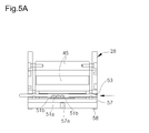
- FIGS. 5A , 5B and 5C are views illustrating operation of releasing the end of the object from the fixed position using the end coupler according to the present invention
- FIG. 6 is a side view illustrating a pressure ring provided in the bobbin fixing apparatus according to the present invention.
- the first magnet 51a is provided in the central portion of the first coupling member 51 and the second magnet 57a is provided in the central portion of the second coupling member 57 such that the second coupling member 57 below the first coupling member 51 is moved upward along the vertically elongated hole 58 so as to come into contact with the first coupling member 51 by attractive force between the first and second magnets 51a and 57a of opposite magnetic polarities in a state in which pressure is not applied to the moving pressure member 53.
- the first magnet 51a is moved in the direction in which the moving pressure member 53 is moved, which causes the first magnet 51a and the second magnet 57a of the second coupling member 57 to be separated from each other to an extent that magnetic attraction therebetween is no longer a factor.
- the second coupling member 57 is moved downward along the vertically elongated hole 58 by repulsive force between the second magnet 57a and the third magnet 51b of like magnetic polarity, thereby being spaced apart from the first coupling member 51 by a separation distance therebetween equal to the length of the hole 58. As such, the end of the object can be released from the fixed position.
- the end coupler 50 further includes a pressure ring 59 configured to be placed on the rotating shaft 30 to apply pressure to one side of the moving pressure member 53 when the rotating body 41 is placed on the rotating shaft 30.
- the pressure ring 59 is configured to an open annular shape so as to be placed on or separated from the rotating shaft 30.
- the pressure ring 59 comes into contact with one end of the moving pressure member 53, located in a direction in which the rotating body 41 is placed on the rotating shaft 30, and applies pressure to the moving pressure member 53 when the bobbin 40 is placed on the rotating shaft 30, thus causing the second coupling member 57 to be moved away from the first coupling member 51 of the end coupler 50.
- the end of the object caught between the first and second coupling members 51 and 57 is released, the object is able to be unwound from the bobbin 40 being rotated by the rotating shaft 30.
- the present invention provides a bobbin fixing apparatus having the following effects.
- a fixing unit is provided at a rotating shaft so as to be inserted into the rotating shaft upon receiving pressure. This allows an operator to conveniently secure a bobbin to the rotating shaft without operating a separate shaft fixing member.
- the shaft fixing member is accommodated in a recess of the rotating shaft so as to be inserted into the rotating shaft when the bobbin is placed on the rotating shaft and then, be returned to an original position thereof by an elastic member, thereby acting to prevent unwanted separation of the bobbin from the rotating shaft. This ensures that a desired object can be wound on or unwound from the bobbin during stable rotation of the bobbin.
- a rotating body of the bobbin is provided with an end coupler to be operated upon receiving pressure.
- the end coupler can keep an end of the object in a fixed position during winding and release the end of the object from the fixed position during unwinding, thereby allowing the object to be wound on or unwound from the bobbin placed on the rotating shaft.
- the end coupler of the present invention can keep the end of the object in a fixed position in a simplified manner using attractive force between first and second magnets of first and second coupling members of the end coupler in a state in which pressure is not applied to a moving pressure member of the end coupler.
- the first and second coupling members are spaced apart from each other by repulsive force between the second magnet of the second coupling member and a third magnet of the first coupling member of like magnetic polarity, thereby allowing the end coupler to release the end of the object from the fixed position.
- the moving pressure member has a symmetrical configuration to allow the operator to apply pressure to one side or the other side of the moving pressure member, which allows the operator to conveniently place the bobbin on the rotating shaft without confirming a direction in which the bobbin is placed on the rotating shaft.
- the first magnet is returned to an original position thereof if pressure applied to the first coupling member is removed, which ensures that the end of the object can be kept in a fixed position or be released from the fixed position in a simplified manner.
- a pressure ring is placed on the rotating shaft to press the moving pressure member.
- the moving pressure member can be pressed when the bobbin is placed on rotating shaft, which allows the end of the object to be kept in a fixed position or released from the fixed position without additional operation, resulting in enhanced operation convenience.
Landscapes
- Unwinding Of Filamentary Materials (AREA)
- Winding Filamentary Materials (AREA)
- Unwinding Webs (AREA)
Applications Claiming Priority (1)
| Application Number | Priority Date | Filing Date | Title |
|---|---|---|---|
| KR1020110014710A KR101691842B1 (ko) | 2011-02-18 | 2011-02-18 | 보빈고정장치 |
Publications (3)
| Publication Number | Publication Date |
|---|---|
| EP2489618A2 true EP2489618A2 (de) | 2012-08-22 |
| EP2489618A3 EP2489618A3 (de) | 2014-01-15 |
| EP2489618B1 EP2489618B1 (de) | 2015-06-17 |
Family
ID=45715184
Family Applications (1)
| Application Number | Title | Priority Date | Filing Date |
|---|---|---|---|
| EP11160328.8A Not-in-force EP2489618B1 (de) | 2011-02-18 | 2011-03-30 | Spulenfixiervorrichtung |
Country Status (3)
| Country | Link |
|---|---|
| US (1) | US8690095B2 (de) |
| EP (1) | EP2489618B1 (de) |
| KR (1) | KR101691842B1 (de) |
Cited By (9)
| Publication number | Priority date | Publication date | Assignee | Title |
|---|---|---|---|---|
| CN103466388A (zh) * | 2013-09-06 | 2013-12-25 | 张家港市霞飞塑业有限公司 | 一种包装带的固定架 |
| CN103708262A (zh) * | 2014-01-09 | 2014-04-09 | 成都先进功率半导体股份有限公司 | 卷盘位置调节装置 |
| CN104276456A (zh) * | 2014-09-24 | 2015-01-14 | 无锡同心塑料制品有限公司 | 泡塑板卡带盘 |
| CN104325796A (zh) * | 2014-10-31 | 2015-02-04 | 苏州佳世达光电有限公司 | 卷筒固定卷轴及标签打印机 |
| EP3192486A3 (de) * | 2012-10-03 | 2017-09-13 | Yuyama Mfg. Co., Ltd. | Arzneimittelprüfsystem, wicklungsvorrichtung, zufuhrvorrichtung und halter |
| CN110963332A (zh) * | 2019-12-30 | 2020-04-07 | 姚益兰 | 一种用于纺织的纱布卷定位装置 |
| CN111908202A (zh) * | 2020-08-11 | 2020-11-10 | 巢湖市鼎盛渔具有限公司 | 一种渔网生产用自动收集扎紧装置 |
| CN112320486A (zh) * | 2020-11-04 | 2021-02-05 | 张小明 | 一种用于电力施工的电线牵引固定架 |
| CN119486601A (zh) * | 2022-05-10 | 2025-02-18 | 复合夹具系统两合公司 | 用于以不同类型的可消耗容器制造香肠形产品的系统 |
Families Citing this family (18)
| Publication number | Priority date | Publication date | Assignee | Title |
|---|---|---|---|---|
| KR20130002696A (ko) * | 2011-06-29 | 2013-01-08 | (주)제이브이엠 | 불량약품 검사장치 |
| US10266361B2 (en) * | 2011-08-31 | 2019-04-23 | Pregis Intellipack Llc | Spindle mechanism for protective packaging device |
| KR101446538B1 (ko) * | 2012-11-29 | 2014-10-06 | 주식회사 유라코퍼레이션 | 수직형 다연발 전선풀림대 |
| JP6466751B2 (ja) * | 2015-03-19 | 2019-02-06 | 株式会社イシダ | フィルムロール支持装置 |
| CN105173909A (zh) * | 2015-07-29 | 2015-12-23 | 安徽丹凤集团桐城玻璃纤维有限公司 | 一种纱管 |
| CN107010443B (zh) * | 2017-03-01 | 2018-10-09 | 袁静 | 一种双轮安装式电热丝卷绕装置 |
| CN107265180A (zh) * | 2017-08-04 | 2017-10-20 | 苏州市远凌纺织有限公司 | 一种纺织线用绕线结构 |
| US10968069B2 (en) * | 2018-02-13 | 2021-04-06 | Aladdin Manufacturing Corporation | Tube holder for line dispensing |
| US11584609B2 (en) | 2018-02-13 | 2023-02-21 | Aladdin Manufacturing Corporation | Tube holder for line dispensing |
| KR200492574Y1 (ko) | 2018-04-20 | 2020-11-05 | 최상만 | 보빈 고정장치 |
| KR101981652B1 (ko) * | 2019-03-12 | 2019-05-23 | 강병우 | 가변 가능한 호스 권치장치 |
| JP7385261B2 (ja) * | 2019-12-04 | 2023-11-22 | 株式会社川島製作所 | 巻取りフィルム支持装置 |
| AT523602B1 (de) * | 2020-03-06 | 2022-04-15 | Haslacher & Haslacher Immobilien Gmbh | Abrolldorn |
| CN111960158A (zh) * | 2020-09-22 | 2020-11-20 | 苏州伟铂瑞信电子科技有限公司 | 一种降低断带风险的电池箔倒卷机 |
| CN113335996B (zh) * | 2021-07-01 | 2022-09-16 | 徐州广朋纺织有限公司 | 一种纺织生产用纱锭放线的限位装置 |
| KR102717126B1 (ko) * | 2022-12-06 | 2024-10-11 | 재단법인 한국탄소산업진흥원 | 그리드 중간재용 섬유 강화 복합재 테이프 권취기 |
| KR20250054511A (ko) | 2023-10-16 | 2025-04-23 | 조경희 | 농업용 점적호스 권취용 보빈 |
| CN118850817B (zh) * | 2024-08-06 | 2025-01-17 | 业展电子(惠州市)有限公司 | 一种辅助人工对编带进行检查的半自动化载带解卷装置 |
Family Cites Families (15)
| Publication number | Priority date | Publication date | Assignee | Title |
|---|---|---|---|---|
| US927604A (en) * | 1907-06-17 | 1909-07-13 | Monarch Typewriter Co | Ribbon-spool for type-writing machines. |
| US2713462A (en) * | 1949-01-08 | 1955-07-19 | Armour Res Found | Tape reel support |
| GB804703A (en) * | 1956-04-26 | 1958-11-19 | Capseals Ltd | Improvements in reels for cables |
| US3033483A (en) * | 1959-08-28 | 1962-05-08 | Cycle Equipment Company | Reel structure for winding of tape |
| CA930225A (en) * | 1969-10-22 | 1973-07-17 | Alex Clark Limited | Photographic developer apparatus |
| US4157793A (en) * | 1977-08-03 | 1979-06-12 | Independent Machine Company | Bobbin winding system |
| JPS60136878U (ja) * | 1984-02-23 | 1985-09-11 | 株式会社神戸製鋼所 | 溶接用ワイヤ巻回装置 |
| DE8615786U1 (de) * | 1986-06-12 | 1986-07-31 | Basf Magnetics Gmbh, 68165 Mannheim | Spannvorrichtung für Magnetband-Wickelkerne |
| JPH0618361U (ja) * | 1992-08-07 | 1994-03-08 | 金井 宏之 | リール保持装置 |
| JPH0647258U (ja) * | 1992-12-03 | 1994-06-28 | 清一 北川 | 糸巻きシリンダーの芯棒 |
| US5645247A (en) * | 1996-02-15 | 1997-07-08 | Karg Corporation | Bobbin post cop locking mechanism |
| US5683058A (en) * | 1996-03-05 | 1997-11-04 | Minnesota Mining And Manufacturing Company | Roll supporting hub |
| EP1950161A4 (de) * | 2005-10-18 | 2009-11-04 | Bridgestone Corp | Spulenkörperbefestigungsvorrichtung und spulenkörperentfernungsvorrichtung |
| KR101529577B1 (ko) * | 2008-10-08 | 2015-06-18 | (주)제이브이엠 | 보빈 고정장치 |
| EP2206636A1 (de) * | 2009-01-07 | 2010-07-14 | Acquaalta Schutzsysteme GmbH | Vorrichtung zum Aufwickeln und Halten eines Dämmelements |
-
2011
- 2011-02-18 KR KR1020110014710A patent/KR101691842B1/ko active Active
- 2011-03-28 US US13/073,009 patent/US8690095B2/en active Active
- 2011-03-30 EP EP11160328.8A patent/EP2489618B1/de not_active Not-in-force
Non-Patent Citations (1)
| Title |
|---|
| None |
Cited By (14)
| Publication number | Priority date | Publication date | Assignee | Title |
|---|---|---|---|---|
| US10858134B2 (en) | 2012-10-03 | 2020-12-08 | Yuyama Mfg. Co., Ltd. | Medicine inspection system, winding device, feed device, and holder |
| EP3192486A3 (de) * | 2012-10-03 | 2017-09-13 | Yuyama Mfg. Co., Ltd. | Arzneimittelprüfsystem, wicklungsvorrichtung, zufuhrvorrichtung und halter |
| CN109592135A (zh) * | 2012-10-03 | 2019-04-09 | 株式会社汤山制作所 | 药剂检查系统、卷绕装置、送料装置、及保持器 |
| CN103466388B (zh) * | 2013-09-06 | 2017-01-11 | 张家港市霞飞塑业有限公司 | 一种包装带的固定架 |
| CN103466388A (zh) * | 2013-09-06 | 2013-12-25 | 张家港市霞飞塑业有限公司 | 一种包装带的固定架 |
| CN103708262A (zh) * | 2014-01-09 | 2014-04-09 | 成都先进功率半导体股份有限公司 | 卷盘位置调节装置 |
| CN104276456A (zh) * | 2014-09-24 | 2015-01-14 | 无锡同心塑料制品有限公司 | 泡塑板卡带盘 |
| CN104325796A (zh) * | 2014-10-31 | 2015-02-04 | 苏州佳世达光电有限公司 | 卷筒固定卷轴及标签打印机 |
| CN110963332B (zh) * | 2019-12-30 | 2021-11-16 | 桐庐万美针纺织有限公司 | 一种用于纺织的纱布卷定位装置 |
| CN110963332A (zh) * | 2019-12-30 | 2020-04-07 | 姚益兰 | 一种用于纺织的纱布卷定位装置 |
| CN111908202A (zh) * | 2020-08-11 | 2020-11-10 | 巢湖市鼎盛渔具有限公司 | 一种渔网生产用自动收集扎紧装置 |
| CN112320486B (zh) * | 2020-11-04 | 2022-07-12 | 国网山东省电力公司乐陵市供电公司 | 一种用于电力施工的电线牵引固定架 |
| CN112320486A (zh) * | 2020-11-04 | 2021-02-05 | 张小明 | 一种用于电力施工的电线牵引固定架 |
| CN119486601A (zh) * | 2022-05-10 | 2025-02-18 | 复合夹具系统两合公司 | 用于以不同类型的可消耗容器制造香肠形产品的系统 |
Also Published As
| Publication number | Publication date |
|---|---|
| EP2489618B1 (de) | 2015-06-17 |
| KR101691842B1 (ko) | 2017-01-02 |
| EP2489618A3 (de) | 2014-01-15 |
| KR20120095194A (ko) | 2012-08-28 |
| US8690095B2 (en) | 2014-04-08 |
| US20120211585A1 (en) | 2012-08-23 |
Similar Documents
| Publication | Publication Date | Title |
|---|---|---|
| EP2489618B1 (de) | Spulenfixiervorrichtung | |
| RU2614597C2 (ru) | Узел диспенсера | |
| EP4026465A1 (de) | Papierhandtuch- oder tissuepapierspender mit rollenüberdrehungskontrolle | |
| KR20190011933A (ko) | 단말기 거치대 및 단말기 케이스 | |
| US4059339A (en) | Brake mechanism for motor driven projection screen | |
| HK1174889A (en) | Bobbin fixing apparatus | |
| US6186439B1 (en) | Rolled product dispenser assembly | |
| JP2014046058A (ja) | トイレットペーパー切断端部の分離装置 | |
| KR200277539Y1 (ko) | 호스릴 | |
| KR101503486B1 (ko) | 코일 인서팅을 위한 모터 코어 안치구 | |
| JP2006168916A5 (de) | ||
| JP7216229B2 (ja) | 釣竿後受け | |
| KR102384235B1 (ko) | 도어 고정장치 | |
| JP6419459B2 (ja) | ラップマシンのフィルム保持装置 | |
| JPH09150996A (ja) | ロール紙保持装置 | |
| KR102198747B1 (ko) | 한 손으로 사용가능한 두루마리 화장지 케이스 | |
| JP2010149990A (ja) | コード巻き取り器 | |
| KR102590918B1 (ko) | 토로이달 코어 권선장치 | |
| CN110004678A (zh) | 绞线盘压线机构和动力机芯及晾衣机 | |
| JP3227768U (ja) | シートロールの支持装置 | |
| US3033483A (en) | Reel structure for winding of tape | |
| JP3194415U (ja) | 裁断装置 | |
| JP3976151B2 (ja) | ホース巻取り装置 | |
| KR200494725Y1 (ko) | 전선릴 | |
| CN216389196U (zh) | 一种用于液压电磁式断路器的油杯固定结构 |
Legal Events
| Date | Code | Title | Description |
|---|---|---|---|
| PUAI | Public reference made under article 153(3) epc to a published international application that has entered the european phase |
Free format text: ORIGINAL CODE: 0009012 |
|
| AK | Designated contracting states |
Kind code of ref document: A2 Designated state(s): AL AT BE BG CH CY CZ DE DK EE ES FI FR GB GR HR HU IE IS IT LI LT LU LV MC MK MT NL NO PL PT RO RS SE SI SK SM TR |
|
| AX | Request for extension of the european patent |
Extension state: BA ME |
|
| REG | Reference to a national code |
Ref country code: HK Ref legal event code: DE Ref document number: 1174889 Country of ref document: HK |
|
| RIC1 | Information provided on ipc code assigned before grant |
Ipc: B65H 75/28 20060101ALI20130913BHEP Ipc: B65H 16/04 20060101AFI20130913BHEP Ipc: B65H 18/02 20060101ALI20130913BHEP Ipc: B65H 75/24 20060101ALI20130913BHEP Ipc: B65H 49/36 20060101ALI20130913BHEP |
|
| PUAL | Search report despatched |
Free format text: ORIGINAL CODE: 0009013 |
|
| AK | Designated contracting states |
Kind code of ref document: A3 Designated state(s): AL AT BE BG CH CY CZ DE DK EE ES FI FR GB GR HR HU IE IS IT LI LT LU LV MC MK MT NL NO PL PT RO RS SE SI SK SM TR |
|
| AX | Request for extension of the european patent |
Extension state: BA ME |
|
| RIC1 | Information provided on ipc code assigned before grant |
Ipc: B65H 49/36 20060101ALI20131212BHEP Ipc: B65H 18/02 20060101ALI20131212BHEP Ipc: B65H 75/28 20060101ALI20131212BHEP Ipc: B65H 16/04 20060101AFI20131212BHEP Ipc: B65H 75/24 20060101ALI20131212BHEP |
|
| 17P | Request for examination filed |
Effective date: 20140715 |
|
| RBV | Designated contracting states (corrected) |
Designated state(s): AL AT BE BG CH CY CZ DE DK EE ES FI FR GB GR HR HU IE IS IT LI LT LU LV MC MK MT NL NO PL PT RO RS SE SI SK SM TR |
|
| GRAP | Despatch of communication of intention to grant a patent |
Free format text: ORIGINAL CODE: EPIDOSNIGR1 |
|
| INTG | Intention to grant announced |
Effective date: 20150106 |
|
| RIN1 | Information on inventor provided before grant (corrected) |
Inventor name: KIM, JUN-HO |
|
| GRAS | Grant fee paid |
Free format text: ORIGINAL CODE: EPIDOSNIGR3 |
|
| GRAA | (expected) grant |
Free format text: ORIGINAL CODE: 0009210 |
|
| AK | Designated contracting states |
Kind code of ref document: B1 Designated state(s): AL AT BE BG CH CY CZ DE DK EE ES FI FR GB GR HR HU IE IS IT LI LT LU LV MC MK MT NL NO PL PT RO RS SE SI SK SM TR |
|
| REG | Reference to a national code |
Ref country code: GB Ref legal event code: FG4D |
|
| REG | Reference to a national code |
Ref country code: CH Ref legal event code: EP |
|
| REG | Reference to a national code |
Ref country code: AT Ref legal event code: REF Ref document number: 731795 Country of ref document: AT Kind code of ref document: T Effective date: 20150715 |
|
| REG | Reference to a national code |
Ref country code: IE Ref legal event code: FG4D |
|
| REG | Reference to a national code |
Ref country code: DE Ref legal event code: R096 Ref document number: 602011017140 Country of ref document: DE |
|
| REG | Reference to a national code |
Ref country code: DE Ref legal event code: R082 Ref document number: 602011017140 Country of ref document: DE Representative=s name: LAVOIX MUNICH, DE Ref country code: DE Ref legal event code: R082 Ref document number: 602011017140 Country of ref document: DE Representative=s name: VON KREISLER SELTING WERNER - PARTNERSCHAFT VO, DE Ref country code: DE Ref legal event code: R082 Ref document number: 602011017140 Country of ref document: DE Representative=s name: DOMPATENT VON KREISLER SELTING WERNER - PARTNE, DE |
|
| PG25 | Lapsed in a contracting state [announced via postgrant information from national office to epo] |
Ref country code: NO Free format text: LAPSE BECAUSE OF FAILURE TO SUBMIT A TRANSLATION OF THE DESCRIPTION OR TO PAY THE FEE WITHIN THE PRESCRIBED TIME-LIMIT Effective date: 20150917 Ref country code: LT Free format text: LAPSE BECAUSE OF FAILURE TO SUBMIT A TRANSLATION OF THE DESCRIPTION OR TO PAY THE FEE WITHIN THE PRESCRIBED TIME-LIMIT Effective date: 20150617 Ref country code: HR Free format text: LAPSE BECAUSE OF FAILURE TO SUBMIT A TRANSLATION OF THE DESCRIPTION OR TO PAY THE FEE WITHIN THE PRESCRIBED TIME-LIMIT Effective date: 20150617 Ref country code: FI Free format text: LAPSE BECAUSE OF FAILURE TO SUBMIT A TRANSLATION OF THE DESCRIPTION OR TO PAY THE FEE WITHIN THE PRESCRIBED TIME-LIMIT Effective date: 20150617 |
|
| REG | Reference to a national code |
Ref country code: NL Ref legal event code: FP |
|
| REG | Reference to a national code |
Ref country code: AT Ref legal event code: MK05 Ref document number: 731795 Country of ref document: AT Kind code of ref document: T Effective date: 20150617 |
|
| REG | Reference to a national code |
Ref country code: LT Ref legal event code: MG4D |
|
| PG25 | Lapsed in a contracting state [announced via postgrant information from national office to epo] |
Ref country code: RS Free format text: LAPSE BECAUSE OF FAILURE TO SUBMIT A TRANSLATION OF THE DESCRIPTION OR TO PAY THE FEE WITHIN THE PRESCRIBED TIME-LIMIT Effective date: 20150617 Ref country code: LV Free format text: LAPSE BECAUSE OF FAILURE TO SUBMIT A TRANSLATION OF THE DESCRIPTION OR TO PAY THE FEE WITHIN THE PRESCRIBED TIME-LIMIT Effective date: 20150617 Ref country code: BG Free format text: LAPSE BECAUSE OF FAILURE TO SUBMIT A TRANSLATION OF THE DESCRIPTION OR TO PAY THE FEE WITHIN THE PRESCRIBED TIME-LIMIT Effective date: 20150917 Ref country code: GR Free format text: LAPSE BECAUSE OF FAILURE TO SUBMIT A TRANSLATION OF THE DESCRIPTION OR TO PAY THE FEE WITHIN THE PRESCRIBED TIME-LIMIT Effective date: 20150918 |
|
| PG25 | Lapsed in a contracting state [announced via postgrant information from national office to epo] |
Ref country code: EE Free format text: LAPSE BECAUSE OF FAILURE TO SUBMIT A TRANSLATION OF THE DESCRIPTION OR TO PAY THE FEE WITHIN THE PRESCRIBED TIME-LIMIT Effective date: 20150617 |
|
| REG | Reference to a national code |
Ref country code: DE Ref legal event code: R082 Ref document number: 602011017140 Country of ref document: DE Representative=s name: VON KREISLER SELTING WERNER - PARTNERSCHAFT VO, DE Ref country code: DE Ref legal event code: R082 Ref document number: 602011017140 Country of ref document: DE Representative=s name: DOMPATENT VON KREISLER SELTING WERNER - PARTNE, DE |
|
| PG25 | Lapsed in a contracting state [announced via postgrant information from national office to epo] |
Ref country code: AT Free format text: LAPSE BECAUSE OF FAILURE TO SUBMIT A TRANSLATION OF THE DESCRIPTION OR TO PAY THE FEE WITHIN THE PRESCRIBED TIME-LIMIT Effective date: 20150617 Ref country code: PL Free format text: LAPSE BECAUSE OF FAILURE TO SUBMIT A TRANSLATION OF THE DESCRIPTION OR TO PAY THE FEE WITHIN THE PRESCRIBED TIME-LIMIT Effective date: 20150617 Ref country code: ES Free format text: LAPSE BECAUSE OF FAILURE TO SUBMIT A TRANSLATION OF THE DESCRIPTION OR TO PAY THE FEE WITHIN THE PRESCRIBED TIME-LIMIT Effective date: 20150617 Ref country code: RO Free format text: LAPSE BECAUSE OF NON-PAYMENT OF DUE FEES Effective date: 20150617 Ref country code: CZ Free format text: LAPSE BECAUSE OF FAILURE TO SUBMIT A TRANSLATION OF THE DESCRIPTION OR TO PAY THE FEE WITHIN THE PRESCRIBED TIME-LIMIT Effective date: 20150617 Ref country code: PT Free format text: LAPSE BECAUSE OF FAILURE TO SUBMIT A TRANSLATION OF THE DESCRIPTION OR TO PAY THE FEE WITHIN THE PRESCRIBED TIME-LIMIT Effective date: 20151019 Ref country code: SK Free format text: LAPSE BECAUSE OF FAILURE TO SUBMIT A TRANSLATION OF THE DESCRIPTION OR TO PAY THE FEE WITHIN THE PRESCRIBED TIME-LIMIT Effective date: 20150617 Ref country code: IS Free format text: LAPSE BECAUSE OF FAILURE TO SUBMIT A TRANSLATION OF THE DESCRIPTION OR TO PAY THE FEE WITHIN THE PRESCRIBED TIME-LIMIT Effective date: 20151017 |
|
| REG | Reference to a national code |
Ref country code: DE Ref legal event code: R097 Ref document number: 602011017140 Country of ref document: DE |
|
| REG | Reference to a national code |
Ref country code: FR Ref legal event code: PLFP Year of fee payment: 6 |
|
| PLBE | No opposition filed within time limit |
Free format text: ORIGINAL CODE: 0009261 |
|
| STAA | Information on the status of an ep patent application or granted ep patent |
Free format text: STATUS: NO OPPOSITION FILED WITHIN TIME LIMIT |
|
| PG25 | Lapsed in a contracting state [announced via postgrant information from national office to epo] |
Ref country code: IT Free format text: LAPSE BECAUSE OF FAILURE TO SUBMIT A TRANSLATION OF THE DESCRIPTION OR TO PAY THE FEE WITHIN THE PRESCRIBED TIME-LIMIT Effective date: 20150617 Ref country code: DK Free format text: LAPSE BECAUSE OF FAILURE TO SUBMIT A TRANSLATION OF THE DESCRIPTION OR TO PAY THE FEE WITHIN THE PRESCRIBED TIME-LIMIT Effective date: 20150617 |
|
| 26N | No opposition filed |
Effective date: 20160318 |
|
| PG25 | Lapsed in a contracting state [announced via postgrant information from national office to epo] |
Ref country code: BE Free format text: LAPSE BECAUSE OF NON-PAYMENT OF DUE FEES Effective date: 20160331 Ref country code: SI Free format text: LAPSE BECAUSE OF FAILURE TO SUBMIT A TRANSLATION OF THE DESCRIPTION OR TO PAY THE FEE WITHIN THE PRESCRIBED TIME-LIMIT Effective date: 20150617 |
|
| PG25 | Lapsed in a contracting state [announced via postgrant information from national office to epo] |
Ref country code: LU Free format text: LAPSE BECAUSE OF FAILURE TO SUBMIT A TRANSLATION OF THE DESCRIPTION OR TO PAY THE FEE WITHIN THE PRESCRIBED TIME-LIMIT Effective date: 20160330 Ref country code: MC Free format text: LAPSE BECAUSE OF FAILURE TO SUBMIT A TRANSLATION OF THE DESCRIPTION OR TO PAY THE FEE WITHIN THE PRESCRIBED TIME-LIMIT Effective date: 20150617 |
|
| REG | Reference to a national code |
Ref country code: CH Ref legal event code: PL |
|
| GBPC | Gb: european patent ceased through non-payment of renewal fee |
Effective date: 20160330 |
|
| REG | Reference to a national code |
Ref country code: IE Ref legal event code: MM4A |
|
| PG25 | Lapsed in a contracting state [announced via postgrant information from national office to epo] |
Ref country code: BE Free format text: LAPSE BECAUSE OF FAILURE TO SUBMIT A TRANSLATION OF THE DESCRIPTION OR TO PAY THE FEE WITHIN THE PRESCRIBED TIME-LIMIT Effective date: 20150617 |
|
| PG25 | Lapsed in a contracting state [announced via postgrant information from national office to epo] |
Ref country code: GB Free format text: LAPSE BECAUSE OF NON-PAYMENT OF DUE FEES Effective date: 20160330 Ref country code: LI Free format text: LAPSE BECAUSE OF NON-PAYMENT OF DUE FEES Effective date: 20160331 Ref country code: IE Free format text: LAPSE BECAUSE OF NON-PAYMENT OF DUE FEES Effective date: 20160330 Ref country code: CH Free format text: LAPSE BECAUSE OF NON-PAYMENT OF DUE FEES Effective date: 20160331 |
|
| REG | Reference to a national code |
Ref country code: FR Ref legal event code: PLFP Year of fee payment: 7 |
|
| PG25 | Lapsed in a contracting state [announced via postgrant information from national office to epo] |
Ref country code: SE Free format text: LAPSE BECAUSE OF FAILURE TO SUBMIT A TRANSLATION OF THE DESCRIPTION OR TO PAY THE FEE WITHIN THE PRESCRIBED TIME-LIMIT Effective date: 20150617 |
|
| PG25 | Lapsed in a contracting state [announced via postgrant information from national office to epo] |
Ref country code: MT Free format text: LAPSE BECAUSE OF FAILURE TO SUBMIT A TRANSLATION OF THE DESCRIPTION OR TO PAY THE FEE WITHIN THE PRESCRIBED TIME-LIMIT Effective date: 20150617 |
|
| REG | Reference to a national code |
Ref country code: FR Ref legal event code: PLFP Year of fee payment: 8 |
|
| PG25 | Lapsed in a contracting state [announced via postgrant information from national office to epo] |
Ref country code: CY Free format text: LAPSE BECAUSE OF FAILURE TO SUBMIT A TRANSLATION OF THE DESCRIPTION OR TO PAY THE FEE WITHIN THE PRESCRIBED TIME-LIMIT Effective date: 20150617 Ref country code: SM Free format text: LAPSE BECAUSE OF FAILURE TO SUBMIT A TRANSLATION OF THE DESCRIPTION OR TO PAY THE FEE WITHIN THE PRESCRIBED TIME-LIMIT Effective date: 20150617 Ref country code: HU Free format text: LAPSE BECAUSE OF FAILURE TO SUBMIT A TRANSLATION OF THE DESCRIPTION OR TO PAY THE FEE WITHIN THE PRESCRIBED TIME-LIMIT; INVALID AB INITIO Effective date: 20110330 |
|
| PG25 | Lapsed in a contracting state [announced via postgrant information from national office to epo] |
Ref country code: TR Free format text: LAPSE BECAUSE OF FAILURE TO SUBMIT A TRANSLATION OF THE DESCRIPTION OR TO PAY THE FEE WITHIN THE PRESCRIBED TIME-LIMIT Effective date: 20150617 Ref country code: MK Free format text: LAPSE BECAUSE OF FAILURE TO SUBMIT A TRANSLATION OF THE DESCRIPTION OR TO PAY THE FEE WITHIN THE PRESCRIBED TIME-LIMIT Effective date: 20150617 Ref country code: MT Free format text: LAPSE BECAUSE OF FAILURE TO SUBMIT A TRANSLATION OF THE DESCRIPTION OR TO PAY THE FEE WITHIN THE PRESCRIBED TIME-LIMIT Effective date: 20160331 |
|
| PG25 | Lapsed in a contracting state [announced via postgrant information from national office to epo] |
Ref country code: AL Free format text: LAPSE BECAUSE OF FAILURE TO SUBMIT A TRANSLATION OF THE DESCRIPTION OR TO PAY THE FEE WITHIN THE PRESCRIBED TIME-LIMIT Effective date: 20150617 |
|
| REG | Reference to a national code |
Ref country code: HK Ref legal event code: WD Ref document number: 1174889 Country of ref document: HK |
|
| PGFP | Annual fee paid to national office [announced via postgrant information from national office to epo] |
Ref country code: NL Payment date: 20240320 Year of fee payment: 14 |
|
| PGFP | Annual fee paid to national office [announced via postgrant information from national office to epo] |
Ref country code: DE Payment date: 20240227 Year of fee payment: 14 |
|
| PGFP | Annual fee paid to national office [announced via postgrant information from national office to epo] |
Ref country code: FR Payment date: 20240320 Year of fee payment: 14 |
|
| REG | Reference to a national code |
Ref country code: DE Ref legal event code: R119 Ref document number: 602011017140 Country of ref document: DE |
|
| REG | Reference to a national code |
Ref country code: NL Ref legal event code: MM Effective date: 20250401 |
|
| PG25 | Lapsed in a contracting state [announced via postgrant information from national office to epo] |
Ref country code: NL Free format text: LAPSE BECAUSE OF NON-PAYMENT OF DUE FEES Effective date: 20250401 |
|
| PG25 | Lapsed in a contracting state [announced via postgrant information from national office to epo] |
Ref country code: DE Free format text: LAPSE BECAUSE OF NON-PAYMENT OF DUE FEES Effective date: 20251001 |
|
| PG25 | Lapsed in a contracting state [announced via postgrant information from national office to epo] |
Ref country code: FR Free format text: LAPSE BECAUSE OF NON-PAYMENT OF DUE FEES Effective date: 20250331 |