EP2489084B1 - Mischungen zur herstellung von photoaktiven schichten für organische solarzellen und organische photodetektoren - Google Patents
Mischungen zur herstellung von photoaktiven schichten für organische solarzellen und organische photodetektoren Download PDFInfo
- Publication number
- EP2489084B1 EP2489084B1 EP10768912.7A EP10768912A EP2489084B1 EP 2489084 B1 EP2489084 B1 EP 2489084B1 EP 10768912 A EP10768912 A EP 10768912A EP 2489084 B1 EP2489084 B1 EP 2489084B1
- Authority
- EP
- European Patent Office
- Prior art keywords
- alkyl
- derivatives
- alkylene
- component
- mass
- Prior art date
- Legal status (The legal status is an assumption and is not a legal conclusion. Google has not performed a legal analysis and makes no representation as to the accuracy of the status listed.)
- Not-in-force
Links
- 0 CC1(C)c(cccc2CCC3)c2N3C1=CC=C(C(C(F)(F)F)=C(C(N1*)=O)C#N)C1=O Chemical compound CC1(C)c(cccc2CCC3)c2N3C1=CC=C(C(C(F)(F)F)=C(C(N1*)=O)C#N)C1=O 0.000 description 4
- RMUIHNGFFCSEBH-UHWBUFEVSA-N CC(C)(C)C(/C(/S1)=C/C=C(\C2(C)C)/N3c4c2cccc4CCC3)=NC1=C(C#N)C#N Chemical compound CC(C)(C)C(/C(/S1)=C/C=C(\C2(C)C)/N3c4c2cccc4CCC3)=NC1=C(C#N)C#N RMUIHNGFFCSEBH-UHWBUFEVSA-N 0.000 description 1
- RTTKVNNZRGYCTK-UHFFFAOYSA-N CC(C=C(N(C)C1=O)O)=C1C#N Chemical compound CC(C=C(N(C)C1=O)O)=C1C#N RTTKVNNZRGYCTK-UHFFFAOYSA-N 0.000 description 1
- XKCYCFSJIDZIQY-KNYYAHOCSA-N CC1(C)c(cccc2CC3)c2N3/C1=C/C=C(/C(C)=C(C(N1C)=O)C#N)\C1=O Chemical compound CC1(C)c(cccc2CC3)c2N3/C1=C/C=C(/C(C)=C(C(N1C)=O)C#N)\C1=O XKCYCFSJIDZIQY-KNYYAHOCSA-N 0.000 description 1
- MJKFKOFXUUDAJL-KPKJPENVSA-N CC1(C)c(cccc2CC3)c2N3/C1=C/C=O Chemical compound CC1(C)c(cccc2CC3)c2N3/C1=C/C=O MJKFKOFXUUDAJL-KPKJPENVSA-N 0.000 description 1
- NHUVNKREZKUWMV-WJEOPBEZSA-N CC1(C)c(cccc2CCC3)c2N3/C1=C/C=C(/C(C)=C(C(N1C)=O)C#N)\C1=O Chemical compound CC1(C)c(cccc2CCC3)c2N3/C1=C/C=C(/C(C)=C(C(N1C)=O)C#N)\C1=O NHUVNKREZKUWMV-WJEOPBEZSA-N 0.000 description 1
- HJCJAGDCBZUXGJ-BQGZOASHSA-N CC1(C)c(cccc2CCC3)c2N3/C1=C/C=C(/C(c1ccccc1)=N1)\SC1=C(C#N)C#N Chemical compound CC1(C)c(cccc2CCC3)c2N3/C1=C/C=C(/C(c1ccccc1)=N1)\SC1=C(C#N)C#N HJCJAGDCBZUXGJ-BQGZOASHSA-N 0.000 description 1
- LXNPXVRUJSKBRD-XWIPEQAGSA-N CC1(C)c2cccc(CCC3)c2N3/C1=C/C=C(/C(C(F)(F)F)=C(C(N1Cc2ccccc2)=O)C#N)\C1=O Chemical compound CC1(C)c2cccc(CCC3)c2N3/C1=C/C=C(/C(C(F)(F)F)=C(C(N1Cc2ccccc2)=O)C#N)\C1=O LXNPXVRUJSKBRD-XWIPEQAGSA-N 0.000 description 1
Classifications
-
- H—ELECTRICITY
- H10—SEMICONDUCTOR DEVICES; ELECTRIC SOLID-STATE DEVICES NOT OTHERWISE PROVIDED FOR
- H10K—ORGANIC ELECTRIC SOLID-STATE DEVICES
- H10K85/00—Organic materials used in the body or electrodes of devices covered by this subclass
- H10K85/60—Organic compounds having low molecular weight
- H10K85/649—Aromatic compounds comprising a hetero atom
- H10K85/652—Cyanine dyes
-
- B—PERFORMING OPERATIONS; TRANSPORTING
- B82—NANOTECHNOLOGY
- B82Y—SPECIFIC USES OR APPLICATIONS OF NANOSTRUCTURES; MEASUREMENT OR ANALYSIS OF NANOSTRUCTURES; MANUFACTURE OR TREATMENT OF NANOSTRUCTURES
- B82Y10/00—Nanotechnology for information processing, storage or transmission, e.g. quantum computing or single electron logic
-
- C—CHEMISTRY; METALLURGY
- C09—DYES; PAINTS; POLISHES; NATURAL RESINS; ADHESIVES; COMPOSITIONS NOT OTHERWISE PROVIDED FOR; APPLICATIONS OF MATERIALS NOT OTHERWISE PROVIDED FOR
- C09B—ORGANIC DYES OR CLOSELY-RELATED COMPOUNDS FOR PRODUCING DYES, e.g. PIGMENTS; MORDANTS; LAKES
- C09B23/00—Methine or polymethine dyes, e.g. cyanine dyes
- C09B23/0091—Methine or polymethine dyes, e.g. cyanine dyes having only one heterocyclic ring at one end of the methine chain, e.g. hemicyamines, hemioxonol
-
- C—CHEMISTRY; METALLURGY
- C09—DYES; PAINTS; POLISHES; NATURAL RESINS; ADHESIVES; COMPOSITIONS NOT OTHERWISE PROVIDED FOR; APPLICATIONS OF MATERIALS NOT OTHERWISE PROVIDED FOR
- C09B—ORGANIC DYES OR CLOSELY-RELATED COMPOUNDS FOR PRODUCING DYES, e.g. PIGMENTS; MORDANTS; LAKES
- C09B23/00—Methine or polymethine dyes, e.g. cyanine dyes
- C09B23/10—The polymethine chain containing an even number of >CH- groups
- C09B23/105—The polymethine chain containing an even number of >CH- groups two >CH- groups
-
- H—ELECTRICITY
- H10—SEMICONDUCTOR DEVICES; ELECTRIC SOLID-STATE DEVICES NOT OTHERWISE PROVIDED FOR
- H10K—ORGANIC ELECTRIC SOLID-STATE DEVICES
- H10K30/00—Organic devices sensitive to infrared radiation, light, electromagnetic radiation of shorter wavelength or corpuscular radiation
- H10K30/30—Organic devices sensitive to infrared radiation, light, electromagnetic radiation of shorter wavelength or corpuscular radiation comprising bulk heterojunctions, e.g. interpenetrating networks of donor and acceptor material domains
-
- H—ELECTRICITY
- H10—SEMICONDUCTOR DEVICES; ELECTRIC SOLID-STATE DEVICES NOT OTHERWISE PROVIDED FOR
- H10K—ORGANIC ELECTRIC SOLID-STATE DEVICES
- H10K30/00—Organic devices sensitive to infrared radiation, light, electromagnetic radiation of shorter wavelength or corpuscular radiation
- H10K30/50—Photovoltaic [PV] devices
-
- H—ELECTRICITY
- H10—SEMICONDUCTOR DEVICES; ELECTRIC SOLID-STATE DEVICES NOT OTHERWISE PROVIDED FOR
- H10K—ORGANIC ELECTRIC SOLID-STATE DEVICES
- H10K30/00—Organic devices sensitive to infrared radiation, light, electromagnetic radiation of shorter wavelength or corpuscular radiation
- H10K30/50—Photovoltaic [PV] devices
- H10K30/57—Photovoltaic [PV] devices comprising multiple junctions, e.g. tandem PV cells
-
- H—ELECTRICITY
- H10—SEMICONDUCTOR DEVICES; ELECTRIC SOLID-STATE DEVICES NOT OTHERWISE PROVIDED FOR
- H10K—ORGANIC ELECTRIC SOLID-STATE DEVICES
- H10K71/00—Manufacture or treatment specially adapted for the organic devices covered by this subclass
- H10K71/10—Deposition of organic active material
- H10K71/16—Deposition of organic active material using physical vapour deposition [PVD], e.g. vacuum deposition or sputtering
- H10K71/164—Deposition of organic active material using physical vapour deposition [PVD], e.g. vacuum deposition or sputtering using vacuum deposition
-
- H—ELECTRICITY
- H10—SEMICONDUCTOR DEVICES; ELECTRIC SOLID-STATE DEVICES NOT OTHERWISE PROVIDED FOR
- H10K—ORGANIC ELECTRIC SOLID-STATE DEVICES
- H10K85/00—Organic materials used in the body or electrodes of devices covered by this subclass
- H10K85/20—Carbon compounds, e.g. carbon nanotubes or fullerenes
- H10K85/211—Fullerenes, e.g. C60
-
- H—ELECTRICITY
- H10—SEMICONDUCTOR DEVICES; ELECTRIC SOLID-STATE DEVICES NOT OTHERWISE PROVIDED FOR
- H10K—ORGANIC ELECTRIC SOLID-STATE DEVICES
- H10K85/00—Organic materials used in the body or electrodes of devices covered by this subclass
- H10K85/20—Carbon compounds, e.g. carbon nanotubes or fullerenes
- H10K85/211—Fullerenes, e.g. C60
- H10K85/215—Fullerenes, e.g. C60 comprising substituents, e.g. PCBM
-
- Y—GENERAL TAGGING OF NEW TECHNOLOGICAL DEVELOPMENTS; GENERAL TAGGING OF CROSS-SECTIONAL TECHNOLOGIES SPANNING OVER SEVERAL SECTIONS OF THE IPC; TECHNICAL SUBJECTS COVERED BY FORMER USPC CROSS-REFERENCE ART COLLECTIONS [XRACs] AND DIGESTS
- Y02—TECHNOLOGIES OR APPLICATIONS FOR MITIGATION OR ADAPTATION AGAINST CLIMATE CHANGE
- Y02E—REDUCTION OF GREENHOUSE GAS [GHG] EMISSIONS, RELATED TO ENERGY GENERATION, TRANSMISSION OR DISTRIBUTION
- Y02E10/00—Energy generation through renewable energy sources
- Y02E10/50—Photovoltaic [PV] energy
- Y02E10/549—Organic PV cells
-
- Y—GENERAL TAGGING OF NEW TECHNOLOGICAL DEVELOPMENTS; GENERAL TAGGING OF CROSS-SECTIONAL TECHNOLOGIES SPANNING OVER SEVERAL SECTIONS OF THE IPC; TECHNICAL SUBJECTS COVERED BY FORMER USPC CROSS-REFERENCE ART COLLECTIONS [XRACs] AND DIGESTS
- Y02—TECHNOLOGIES OR APPLICATIONS FOR MITIGATION OR ADAPTATION AGAINST CLIMATE CHANGE
- Y02P—CLIMATE CHANGE MITIGATION TECHNOLOGIES IN THE PRODUCTION OR PROCESSING OF GOODS
- Y02P70/00—Climate change mitigation technologies in the production process for final industrial or consumer products
- Y02P70/50—Manufacturing or production processes characterised by the final manufactured product
Definitions
- organic semiconductors based on low-molecular or polymeric materials will increasingly be used in addition to the classical inorganic semiconductors.
- These have many advantages over the classical inorganic semiconductors, for example a better substrate compatibility and a better processability of the semiconductor components based on them. They allow processing on flexible substrates and allow their frontier orbital energies to be precisely adapted to the respective field of application using molecular modeling methods. The significantly reduced cost of such components has brought a renaissance to the field of organic electronics research.
- Organic Electronics is the development of new materials and manufacturing processes for the production of electronic components based on organic semiconductor layers. These include above all organic field-effect transistors (OFET) as well as organic light-emitting diodes (OLEDs, for example for use in displays) and organic photovoltaics.
- OFET organic field-effect transistors
- OLEDs organic light-emitting diodes
- the direct conversion of solar energy into electrical energy in solar cells is based on the internal photoelectric effect of a semiconductor material, ie the generation of electron-hole pairs by absorption of photons and separation of the negative and positive charge carriers at a pn junction or Schottky contact.
- the photovoltaic voltage thus generated can cause a photocurrent in an external circuit, through which the solar cell gives off its power.
- the semiconductor can absorb only those photons that have an energy that is greater than its band gap.
- the size of the semiconductor band gap thus determines the proportion of sunlight that can be converted into electrical energy.
- organic solar cells will outperform the traditional silicon-based solar cells because of lower cost, lower weight, the ability to produce flexible and / or colored cells, better ability to fine tune the bandgap. There is thus a great need for organic semiconductors which are suitable for the production of organic solar cells.
- organic solar cells In order to use solar energy as effectively as possible, organic solar cells usually consist of two absorbing materials with different electron affinity or different ionization behavior. One material then acts as a p-type conductor (electron donor), the other as an n-type conductor (electron acceptor).
- the first organic solar cells consisted of a two-layer system of a copper phthalocyanine as the p-type conductor and PTCBI as the n-type conductor and showed an efficiency of 1%.
- relatively high layer thicknesses are used (eg 100 nm).
- the excited state generated by the absorbed photons must reach a p-n junction to produce a hole and an electron, which then flows to the anode and cathode.
- most organic semiconductors only have excited state diffusion lengths of up to 10 nm. Even by the best known fabrication techniques, the distance over which the excited state must be propagated can be reduced to a minimum of 10 to 30 nm.
- the photoactive layer contains the acceptor and donor compound (s) as a bicontinuous phase.
- acceptor and donor compound s
- the photoactive layer contains the acceptor and donor compound (s) as a bicontinuous phase.
- polymers such as polyvinylphenylenes or polythiophenes, or dyes from the class of phthalocyanines, z.
- Zn or Vanadylphthalocyanin As Zn or Vanadylphthalocyanin, and used as acceptor fullerene and fullerene derivatives and various perylenes.
- Photoactive layers of the donor / acceptor pairs Poly (3-hexylthiophene) (“P3HT”) / [6,6] -phenyl-C 61 -butylic acid methyl ester (“PCBM”), poly (2- methoxy-5- (3,7-dimethyloctyloxy) -1,4-phenylenevinylene) (“OC 1 C 10 -PPV”) / PCBM and Zn phthalocyanine / fullerene.
- P3HT Poly (3-hexylthiophene)
- PCBM poly (2- methoxy-5- (3,7-dimethyloctyloxy) -1,4-phenylenevinylene
- Halogen refers to fluorine, chlorine, bromine and iodine, in particular fluorine and chlorine.
- Alkyl is to be understood as meaning substituted or unsubstituted C 1 -C 20 -alkyl radicals. Preference is given to C 1 - to C 10 -alkyl radicals, more preferably C 1 - to C 6 -alkyl radicals.
- the alkyl radicals can be both straight-chain and branched.
- the alkyl radicals may be substituted with one or more substituents selected from the group consisting of C 1 -C 20 alkoxy, halogen, preferably F, and C 6 -C 30 -aryl, which in turn may be substituted or unsubstituted substituted. Suitable aryl substituents as well as suitable alkoxy and halogen substituents are mentioned below.
- alkyl groups are methyl, ethyl, propyl, butyl, pentyl, hexyl, heptyl and octyl as well as with C 6 -C 30 -aryl, C 1 -C 20 -alkoxy and / or halogen, in particular F, substituted derivatives of mentioned alkyl groups, for example CF 3 .
- n-isomers of said radicals and branched isomers such as isopropyl, isobutyl, isopentyl, sec-butyl, tert-butyl, neopentyl, 3,3-dimethylbutyl, 3-ethylhexyl, etc. are included.
- Preferred alkyl groups are methyl, ethyl, propyl, tert-butyl and CF 3 .
- cycloalkyl substituted or unsubstituted C 3 -C 20 -alkyl radicals. Preference is given to C 3 - to C 10 -alkyl radicals, more preferably C 3 - to C 8 -alkyl radicals.
- the cycloalkyl radicals may carry one or more of the substituents mentioned with respect to the alkyl radicals.
- cyclic alkyl groups which may likewise be unsubstituted or substituted by the radicals mentioned above with respect to the alkyl groups are cyclopropyl, cyclobutyl, cyclopentyl, cyclohexyl, cycloheptyl, cyclooctyl, cyclononyl and cyclodecyl.
- it may also be polycyclic ring systems, such as decalinyl, norbornyl, bornanyl or adamantyl.
- alkyl which is interrupted by one or two non-adjacent oxygen atoms is, for example, 3-methoxyethyl, 2- and 3-methoxy-propyl, 2-ethoxyethyl, 2- and 3-ethoxypropyl, 2-propoxyethyl, 2- and 3-propoxypropyl
- 2-butoxyethyl, 2- and 3-butoxypropyl, 3,6-dioxaheptoyl and 3,6-dioxaoctyl is, for example, 3-methoxyethyl, 2- and 3-methoxy-propyl, 2-ethoxyethyl, 2- and 3-ethoxypropyl, 2-propoxyethyl, 2- and 3-propoxypropyl.
- Suitable aryls are C 6 -C 30 -aryl radicals which are derived from monocyclic, bicyclic or tricyclic aromatics which contain no ring heteroatoms. Unless they are monocyclic systems, the term aryl for the second ring also means the saturated form (perhydroform) or the partially unsaturated form (for example the dihydroform or tetrahyroform), provided the respective forms are known and stable. That is, in the present invention, the term aryl includes, for example, bicyclic or tricyclic radicals in which both both and all three radicals are aromatic, as well as bicyclic or tricyclic radicals in which only one ring is aromatic, and tricyclic radicals wherein two rings are aromatic.
- aryl examples include: phenyl, naphthyl, indanyl, 1,2-dihydronaphthenyl, 1,4-dihydronaphthenyl, indenyl, anthracenyl, phenanthrenyl or 1,2,3,4-tetrahydronaphthyl.
- Particularly preferred are C 6 -C 10 -aryl radicals, for example phenyl or naphthyl, very particularly preferably C 6 -aryl radicals, for example phenyl.
- R in the abovementioned groups is in particular C 1 -C 20 -alkyl or C 6 -C 30 -aryl.
- C 1 -C 6 -alkylene-COO-alkyl, C 1 -C 6 -alkylene-O-CO-alkyl and C 1 -C 6 -alkylene-O-CO-O-alkyl are derived from the previously described alkyl radicals by attachment C 1 -C 6 -alkylene COO, C 1 -C 6 -alkylene-O-CO and C 1 -C 6 -alkylene-O-CO-O, in which the C 1 -C 6 -alkylene Units are preferably linear. In particular, C 2 -C 4 -alkylene units come into consideration.
- Arylalkyl in particular aryl-C 1 -C 20 -alkyl groups are mentioned. They are derived from the abovementioned alkyl and aryl groups by formal replacement of a hydrogen atom of the linear or branched alkyl chain by an aryl group. For example, may be mentioned as the preferred arylalkyl benzyl.
- the hetaryl radicals have 5 to 13 ring atoms.
- the backbone of the heteroaryl radicals selected from systems such as pyridine and five-membered heteroaromatics such as thiophene, pyrrole, imidazole or furan. These backbones may optionally be fused with one or two six-membered aromatic radicals. Suitable fused Heteroaromatics are carbazolyl, benzimidazolyl, benzofuryl, dibenzofuryl or dibenzothiophenyl.
- the backbone may be substituted at one, several or all substitutable positions, suitable substituents being the same as those already mentioned under the definition of C 6 -C 30 -aryl.
- hetaryl radicals are preferably unsubstituted.
- Suitable hetaryl radicals are, for example, pyridin-2-yl, pyridin-3-yl, pyridin-4-yl, thiophen-2-yl, thiophen-3-yl, pyrrol-2-yl, pyrrol-3-yl, furan-2 -yl, furan-3-yl and imidazol-2-yl and the corresponding benzanell faced radicals, in particular carbazolyl, benzimidazolyl, benzofuryl, dibenzofuryl or dibenzothiophenyl.
- the component K1 can take over the role of electron donor, according to the component K2 then comes the role of the electron acceptor. Alternatively, however, the component K1 can also assume the role of the electron acceptor, and accordingly component K2 acts as an electron donor.
- the way in which the respective component acts depends on the energy of the HOMO or LUMO of the component K1 in relation to the energy of the HOMO or LUMO of the component K2.
- the compounds of component K1 are typically merocyanines, which usually appear as electron donors. In particular, this is the case when used as component K2 rylene or fullerene derivatives, which then usually act as electron acceptors. However, these roles can be reversed in a specific case.
- component K2 can also obey the structural definition of component K1, so that one compound of formula la can take on the role of the electron donor and another compound of formula la can play the role of the electron acceptor.
- mixtures which are characterized in that component K2 is one or more fullerenes and / or fullerene derivatives.
- C 1 -C 10 -alkylene is understood in particular to mean a linear chain - (CH 2 ) m -, where m is 1, 2, 3, 4, 5, 6, 7, 8, 9 or 10.
- fullerene derivatives are used according to the invention in which R 'is a C 1 -C 4 -alkyl, in particular a methyl radical, Q is a propylene chain - (CH 2 ) 3 - and R "is an optionally substituted phenyl
- the fullerene derivative is [6,6] -phenyl-C 61 -butylklaremethylester ("PCBM").
- fullerenes are C 60 , C 70 , C 76 , C 80 , C 82 , C 84 , C 86 , C 90 and C 94 , in particular C 60 and C 70 .
- fullerenes which can be used according to the invention, provides, for example, the monograph of A. Hirsch, M. Brettreich, "Fullerenes: Chemistry and Reactions", Wiley-VCH, Weinheim 2005 ,
- component K2 is a C60 fullerene of the formula k2
- the mixtures to be used according to the invention are characterized in that component K1 is present in a proportion of 10 to 90% by mass, in particular 20 to 80% by mass, and component K2 in a proportion of 90 to 10% by mass, in particular 80% to 20% by mass, is present, wherein the proportions of the components K1 and K2, in each case based on the total mass of the components K1 and K2, add up to 100% by mass.
- the isomeric compounds of the formula Ia and the isomers of the corresponding preferred compounds and mixtures of isomers are also to be included.
- a process for the production of photoactive layers is claimed, which is characterized in that one or more of the compounds of general formula Ia of component K1, also taking into account their preferences, and one or more compounds The component K2, also taking into account their preferences, at the same time, sequentially or in an alternating sequence by vacuum sublimation deposited on a substrate.
- the method is characterized in that the component K1 in a proportion of 10 to 90% by mass, in particular 20 to 80% by mass, and the component K2 in a proportion of 90 to 10% by mass, in particular 80 to 20 mass -%, is deposited on the substrate, wherein the proportions of the components K1 and K2, in each case based on the total mass of the components K1 and K2, add up to 100% by mass.
- organic solar cells and organic photodetectors which contain photoactive layers which have been produced using the above-described mixtures containing components K1 and K2 or using the preferred embodiments of the mixtures also described above.
- Organic solar cells are usually layered and usually comprise at least the following layers: electrode, photoactive layer and counter electrode. These layers are usually on a conventional substrate.
- Suitable substrates include oxidic materials such as glass, quartz, ceramics, SiO 2 , etc., polymers such as polyvinyl chloride, polyolefins such as polyethylene and polypropylene, polyesters, fluoropolymers, polyamides, polyurethanes, polyalkyl (meth) acrylates, polystyrene and mixtures and composites thereof, and combinations of the aforementioned substrates.
- Suitable materials for the one electrode are in particular metals, such as the alkali metals Li, Na, K, Rb and Cs, the alkaline earth metals Mg, Ca and Ba, Pt, Au, Ag, Cu, Al, In, metal alloys, eg based on Pt, Au, Ag, Cu, etc., and special Mg / Ag alloys, but also alkali metal fluorides such as LiF, NaF, KF, RbF and CsF, and mixtures of alkali metal fluorides and alkali metals.
- the electrode used is preferably a material that essentially reflects the incident light. These include, for example, metal films of Al, Ag, Au, In, Mg, Mg / Al, Ca, etc.
- the counter electrode consists of a material substantially transparent to incident light, e.g. As ITO, doped ITO, ZnO, TiO 2 , Cu, Ag, Au and Pt, the latter metals are present in correspondingly thin layers.
- an electrode / counterelectrode should be regarded as "transparent” if at least 50% of the radiation intensity is transmitted in the wavelength range in which the photoactive layer absorbs radiation. In the case of several photoactive layers, an electrode / counterelectrode should be considered “transparent” if at least 50% of the radiation intensity is transmitted in the wavelength ranges in which the photoactive layers absorb radiation.
- one or more further layers may be present in the organic solar cells and photodetectors according to the invention, for example electron transporting layers (ETL) and / or hole transporting layers (HTL) and / or or blocking layers, eg exciton blocking layers ("EBL", exciton blocking layers), which usually do not absorb the incident light, or also layers which serve as charge transport layers and at the same time improve the contacting to one or both electrodes of the solar cell.
- ETL and HTL may also be doped to give pin-type cells, as described, for example, in the publication of Drechsel, et al., Thin Solid Films 451-452 (2004), 515-517 , are described.
- Layer 11 is a transparent, conductive layer, for example ITO, FTO or ZnO, which is optionally pretreated, for example, with oxygen plasma, UV / ozone rinsing, etc.
- this layer must be so thin that only low light absorption, on the other hand, is thick enough to ensure satisfactory lateral charge transport within the layer.
- the thickness of the layer is 20-200 nm and it is deposited on a substrate such as glass or a flexible polymer (for example PET).
- Layer 12 consists of one or more HTLs with a high ionization potential (> 5.0 eV, preferably 5.5 eV).
- This layer can either consist of organic material, such as poly (3,4-ethylenedioxythiophene) doped with poly (styrenesulfonate) (PEDOT-PSS), or, for example, of Ir-DPBIC (Tris-N, N'-diphenylbenzimidazol-2-ylidene).
- the layer thickness is 0 -
- layer 12 is made of organic material, it can be mixed with a p-type dopant whose LUMO energy is in the same or lower energy range as the HOMO of HTL.
- dopants are, for example, 2,3,5,6-tetrafluoro-7,7,8,8-tetracyanoquinodimethane (F 4 TCNQ), WO 3 , MoO 3 , or those in the document WO 2007/071450 A1 described substances.
- Layer 13 consists of the electron donor. Usually, the layer should be so thick that it absorbs as much light as possible, but on the other hand, sufficiently thin, in order to be able to effectively dissipate the charges formed. As a rule, the thickness is 5-200 nm.
- Layer 14 consists of the electron acceptor. Again, as for layer 13, the thickness should be sufficient to absorb as much light as possible, but on the other hand, the charges formed must be effectively dissipated. Usually, this layer also has a thickness of 5-200 nm.
- Layer 15 is an EBL / ETL and should have a larger optical bandgap than the materials of layer 14 to reflect the exitons, yet still have sufficient electron transport properties.
- Suitable compounds are 2,9-dimethyl-4,7-diphenyl-1,10-phenanthroline (BCP), 4,7-diphenyl-1,10-phenanthroline (Bphen), 1,3-bis [2- (2, 2'-bipyridin-6-yl) 1,3,4-oxadizo-5-yl] benzene (BPY-OXD), ZnO, TiO 2, etc.
- BCP 2,9-dimethyl-4,7-diphenyl-1,10-phenanthroline
- Bphen 4,7-diphenyl-1,10-phenanthroline
- BPY-OXD 1,3-bis [2- (2, 2'-bipyridin-6-yl) 1,3,4-oxadizo-5-yl] benzene
- ZnO TiO 2 etc.
- Suitable materials are Cs 2 CO 3 , pyronin B (PyB), described for example in the document WO 2003/070822 A2 Rodamine B described, for example, in Scripture WO 2005/036667 A1 , Cobaltocene and those in the Scriptures WO 2007/071450 A1 mentioned connections.
- the layer thickness is usually 0-150 nm.
- Layer 16 is made of a low work function material.
- these are metals such as Ag, Al, Ca, Mg or mixtures thereof.
- the layer thickness is usually 50-1000 nm and should be chosen sufficiently so that most of the light is reflected in the wavelength range of 350 - 1200 nm.
- the usual pressures during the vapor deposition are between 10 -4 and 10 -9 mbar.
- the deposition rate usually varies between 0.01 nm / second and 10 nm / second.
- the temperature of the substrate during the deposition can be varied in a temperature range between -100 ° C and 200 ° C in order to influence the morphology of the corresponding layer targeted.
- the deposition rate is usually between 0.1 nm / second and 2.0 nm / second.
- the layers 21 and 22 correspond to the layers 11 and 12 of structure A).
- the layer 23 may be prepared by co-evaporation or by solution processing with common solvents - discussed below.
- the proportion of the electron donor in both cases is preferably 10 to 90% by mass, especially 20 to 80% by mass.
- the proportion of electron acceptor is in addition to 100% by mass.
- the layer must be so thick that enough light is absorbed, but still so thin that the charge carriers can be effectively dissipated.
- the layer is 5 - 500 nm thick.
- the ETL layer 24 may consist of one or more layers of low LUMO energy ( ⁇ 3.5 eV) materials. These layers can either consist of organic compounds, such as C60 fullerene, BCP, Bphen or BPY-OXD, or of inorganic compounds, such as ZnO, TiO 2, etc., and are generally between 0 nm and 150 nm thick. In the case of organic layers, these may be mixed with the dopants already mentioned above.
- Layers 25 and 26 correspond to layers 15 and 16 of structure A). Similarly, the deposition rates and aftertreatments correspond to those of structure A).
- Tandem cells contain two or more subcells, which are usually connected in series, with recombination layers being arranged between the individual subcells.
- Layer 31 corresponds to the structure of the aforementioned layers 11 and 21 of structure A) and B).
- the layers 32 and 34 are individual subcells and correspond in function to individual cells as in structure A) and B), with the difference that they do not contain electrodes 11/16 and 21/26.
- the subcells therefore consist of the layers 12 to 15 of the structure A) or 22 to 25 of the structure B).
- the sub-cells can either contain all merocyanines as component K1 or K2 or a sub-cell contains one or more merocyanines and the remaining sub-cells contain combinations of other materials, such as C60-fullerene / Zn-phthalocyanine, oligothiophene (for example DCV5T) / C60-fullerene ( as in WO 2006/092134 A1 or one of the sub-cells is a dye-sensitized solar cell (DSSC) or a polymer cell, such as in the combination P3HT / PCBM. Furthermore, both cells of structure A) and of structure B) can be contained as subcells.
- DSSC dye-sensitized solar cell
- the combination of materials / subcells is chosen such that the light absorptions of the subcells do not overlap too much, but in total cover the spectrum of the sunlight, which leads to an increase in the current efficiency.
- the recombination layer 33 causes the recombination of oppositely charged charge carriers in adjacent subcells.
- metal clusters for example of Ag or Au, act or the recombination layer consists of a combination of highly doped n- and p-type layers (such as in WO 2004/083958 A2 described).
- layer thicknesses of 0.5 to 20 nm are usually set, and in the case of the combined doped layers, thicknesses of 5 to 150 nm are set.
- Further subcells can be applied to the subcell 34, in which case further recombination layers, such as layer 33, must also be present.
- the material for the electrode 36 depends on the polarity of the subcells. At normal polarity, the aforementioned low work function metals, such as Ag, Al, Mg, and Ca, come into consideration. In inverted polarity, high work function materials are commonly used, such as Au, Pt, PEDOT-PSS.
- tandem cells which contain subcells connected in series
- the sub-voltages add up, but the total current is limited by the sub-cell with the lowest current / current density. Therefore, the individual subcells should be optimized so that their individual current strengths / current densities have similar values.
- Photodetectors essentially have a structure analogous to organic solar cells, but they are operated with a suitable bias voltage which, when exposed to radiation energy, generates a corresponding current flow as a measurement response.
- the processing of the photoactive layers can be carried out from solution.
- the components K1 and K2 can already be solved together, but also separately as a solution of the component K1 and solution of the component K2, the mixing of the corresponding solutions in the latter case occurs shortly before application to the underlying layer.
- the concentrations of components K1 and K2 are typically about a few g / l to tens of g / l of solvent.
- Suitable solvents are all liquids which evaporate without residue and have sufficient solubility for the components K1 and K2.
- aromatic compounds such as benzene, toluene, xylene, mesitylene, chlorobenzene or dichlorobenzene, trialkylamines, nitrogen-containing heterocycles, N, N-disubstituted aliphatic carboxylic acid amides such as dimethylformamide, diethylformamide, dimethylacetamide or dimethylbutyramide, N-alkyllyllams such as such as N-methylpyrrolidone, linear and cyclic ketones such as methyl ethyl ketone, cyclopentanone or cyclohexanone, cyclic ethers such as tetrahydrofuran, or alcohols such as methanol, ethanol, propanol, isopropanol or butanol.
- mixtures of the abovementioned solvents can also be used.
- Suitable methods for applying the photoactive layers of the invention of the liquid phase are known in the art.
- the processing by means of spin coating is advantageous, since the thickness of the photoactive layer can be controlled in a simple manner by the amount and / or concentration of the solution used and the rotational speed and / or rotation time.
- the processing of the solution is usually carried out at room temperature.
- the components K1 and K2 are separated from the gas phase, in particular by vacuum sublimation. Since the compounds of the formula Ia can generally be purified by sublimation, starting parameters for the gas phase separation can already be derived therefrom. Usually temperatures between 100 and 200 ° C are used for the deposition, but they can also, depending on the stability of the compounds of the components K1 and K2 also be increased to a range of 300 to 400 ° C.
- mixtures are also claimed which comprise as components one or more of the compounds of general formula Ia of component K1, also taking into account the preferences given, and one or more compounds of component K2, likewise taking into account their preferred preferences , contain.
- the mixtures according to the invention are characterized in that the component K1 in a proportion of 10 to 90% by mass, in particular 20 to 80% by mass, and the component K2 in a proportion of 90 to 10% by mass, in particular 80 to 20% by mass, is present, wherein the proportions of the components K1 and K2, in each case based on the total mass of the components K1 and K2, add up to 100% by mass.
- the ITO was sputtered onto the glass substrate to a thickness of 140 nm.
- the resistivity was 200 ⁇ cm and the roughness mean square (RMS) ⁇ 5 nm.
- the substrate was treated with ozone for 20 minutes prior to deposition of the further layers under UV light.
- Cells of structure A) and B) were prepared under high vacuum (pressure ⁇ 10 -6 mbar).
- the cell of structure A) (ITO / merocyanine / C60 / Bphen / Ag) was prepared by sequential deposition of the merocyanine and C60 on the ITO substrate. The deposition rate was 0.1 nm / second for both layers. The evaporation temperatures of the merocyanines are listed in Table 1. C60 was at 400 ° C deposited. After the Bphen layer had been applied, finally, a 100 nm thick Ag layer was vapor-deposited as a top electrode. The cell had an area of 0.031 cm 2 .
- composition B ITO / (merocyanine: C60 - 1: 1 by weight) / C60 / Bphen / Ag
- the merocyanine and the C60 were coevaporated and deposited on the ITO at the same deposition rate of 0.1 nm / Second applied, so that in the mixed active layer, a mass ratio of 1: 1 was present.
- the Bphen and Ag layers were identical to the corresponding layers of structure A).
- the data of a cell with BHJ layer on a doped HTL are listed in Table 3.
- NPD and F 4 -TCNQ were evaporated as HTL and dopant in a mass ratio of 20: 1.
- the HTL layer improved the voltage V oc in the absence of current (oc: open circuit) and provided higher efficiencies.
- An AM 1.5 simulator from Solar Light Co. Inc. with xenon lamp (model 16S-150 V3) was used.
- the UV range below 415 nm was filtered out and the current-voltage measurements were made at ambient conditions.
- the intensity of the solar simulator was calibrated with a monocrystalline FZ solar cell (Fraunhofer ISE) and the deviation factor was determined to be almost 1.0.
Landscapes
- Chemical & Material Sciences (AREA)
- Engineering & Computer Science (AREA)
- Physics & Mathematics (AREA)
- Materials Engineering (AREA)
- Organic Chemistry (AREA)
- Nanotechnology (AREA)
- Electromagnetism (AREA)
- Spectroscopy & Molecular Physics (AREA)
- Mathematical Physics (AREA)
- Theoretical Computer Science (AREA)
- Crystallography & Structural Chemistry (AREA)
- Manufacturing & Machinery (AREA)
- Photovoltaic Devices (AREA)
- Nitrogen Condensed Heterocyclic Rings (AREA)
Description
- Die vorliegende Erfindung betrifft die Verwendung von Mischungen, enthaltend als Komponenten
- K1) eine oder mehrere Verbindungen ausgewählt aus der Gruppe der Verbindungen der allgemeinen Formel

- A
- eine Brücke bestehend aus zwei oder drei sp3-hybridisierten Kohlenstoffatomen, in welcher jedes Kohlenstoffatom zusätzlich noch mit je einem Substituenten R101 substituiert oder welche benzanelliert sein kann,
- W
- C(CN)2,
- L
- ein zweiwertiger, gegebenenfalls ein- oder mehrfach anellierter Carbo- oder Heterocyclus,
- n
- 1,
- X100
- CH,
- X200
- C(R111)2,
- R100
- H, Alkyl, C1-C6-Alkylen-COO-Alkyl, C1-C6-Alkylen-O-CO-Alkyl, C1-C6- Alkylen-O-CO-O-Alkyl, Cylcloalkyl, Arylalkyl, Aryl, OR110, SR110, Hetaryl, Halogen, NO2 oder CN,
- R101
- Alkyl, C1-C6-Alkylen-COO-Alkyl, C1-C6-Alkylen-O-CO-Alkyl, C1-C6- Alkylen-O-CO-O-Alkyl, Cylcloalkyl, Arylalkyl, Aryl oder Hetaryl,
- R110
- H, Alkyl, C1-C6-Alkylen-COO-Alkyl, C1-C6-Alkylen-O-CO-Alkyl, C1-C6- Alkylen-O-CO-O-Alkyl, Cylcloalkyl, Arylalkyl oder Aryl,
- R111
- H, Alkyl, C1-C6-Alkylen-COO-Alkyl, C1-C6-Alkylen-O-CO-Alkyl, C1-C6- Alkylen-O-CO-O-Alkyl, Cylcloalkyl, Arylalkyl, Aryl oder Hetaryl,
wobei die Kohlenstoffketten der Alkyl- und Cylcloalkyl-Reste durch ein oder zwei nichtbenachbarte Sauerstoffatome unterbrochen sein können, und die zuvor genannten Variablen, sofern sie mehr als einmal auftreten, gleich oder voneinander verschieden sein können
- K2) eine oder mehrere Verbindungen, welche gegenüber Komponente K1) entsprechend als Elektronenakzeptor bzw. Elektronendonor wirken,
- Es wird erwartet, dass zukünftig in vielen Bereichen der Elektronikindustrie neben den klassischen anorganischen Halbleitern zunehmend auch organische Halbleiter auf Basis von niedermolekularen oder polymeren Materialien eingesetzt werden. Diese weisen vielfach Vorteile gegenüber den klassischen anorganischen Halbleitern auf, beispielsweise eine bessere Substratkompatibilität und eine bessere Verarbeitbarkeit der auf ihnen basierenden Halbleiterbauteile. Sie erlauben die Verarbeitung auf flexiblen Substraten und ermöglichen es, ihre Grenzorbitalenergien mit den Methoden des Molecular Modellings auf den jeweiligen Anwendungsbereich genau anzupassen. Die deutlich verringerten Kosten derartiger Bauteile haben dem Forschungsgebiet der organischen Elektronik eine Renaissance gebracht. Die "Organische Elektronik" beschäftigt sich schwerpunktmäßig mit der Entwicklung neuer Materialien und Fertigungsprozesse für die Herstellung elektronischer Bauelemente auf der Basis organischer Halbleiterschichten. Dazu zählen vor allem organische Feldeffekttransistoren (Organic Field-Effect Transistors, OFET) sowie organische Leuchtdioden (Organic Light Emitting Diodes, OLED; z.B. für den Einsatz in Displays) und die organische Photovoltaik.
- Die Direktumwandlung von Solarenergie in elektrische Energie in Solarzellen beruht auf dem inneren Photoeffekt eines Halbleitermaterials, d.h. der Erzeugung von Elektron-Loch-Paaren durch Absorption von Photonen und der Trennung der negativen und positiven Ladungsträger an einem p-n-Übergang oder einem Schottky-Kontakt. Die so erzeugte Photospannung kann in einem äußeren Stromkreis einen Photostrom bewirken, durch den die Solarzelle ihre Leistung abgibt.
- Vom Halbleiter können dabei nur solche Photonen absorbiert werden, die eine Energie aufweisen, die größer als seine Bandlücke ist. Die Größe der Halbleiterbandlücke bestimmt also den Anteil des Sonnenlichts, der in elektrische Energie umgewandelt werden kann. Es wird zukünftig erwartet, dass organische Solarzellen die klassischen Solarzellen auf Siliziumbasis aufgrund geringerer Kosten, eines geringeren Gewichts, der Möglichkeit zur Herstellung flexibler und/oder farbiger Zellen, der besseren Möglichkeit zur Feinabstimmung des Bandabstands übertreffen werden. Es besteht somit ein großer Bedarf an organischen Halbleitern, die sich zur Herstellung organischer Solarzellen eignen.
- Um die Sonnenenergie möglichst effektiv zu nutzen bestehen organische Solarzellen normalerweise aus zwei absorbierenden Materialien mit unterschiedlicher Elektronenaffinität bzw. unterschiedlichem lonisationsverhalten. Das eine Material wirkt dann als p-Leiter (Elektronendonor), das andere als n-Leiter (Elektronenakzeptor). Die ersten organischen Solarzellen bestanden aus einem zweilagigen System aus einem KupferPhthalocyanin als p-Leiter und PTCBI als n-Leiter und zeigten einen Wirkungsgrad von 1 %. Um möglichst alle auftreffenden Photonen zu nutzen, werden relativ hohe Schichtdicken eingesetzt (z. B. 100 nm). Um Strom zu erzeugen, muss der durch die absorbierten Photonen erzeugte angeregte Zustand jedoch eine p-n-Grenzschicht ("p-n-junction") erreichen, um ein Loch und ein Elektron zu erzeugen, welches dann zur Anode und Kathode fließt. Die meisten organischen Halbleiter haben jedoch nur Diffusionslängen für den angeregten Zustand von bis zu 10 nm. Selbst durch die besten bisher bekannten Herstellverfahren kann die Distanz, über die der angeregte Zustand weitergeleitet werden muss, auf minimal 10 bis 30 nm verringert werden.
- Neuere Entwicklungen in der organischen Photovoltaik gehen in die Richtung der sogenannten "Bulk-Heterojunction": die photoaktive Schicht enthält hierbei die Akzeptor- und Donorverbindung(en) als bikontinuierliche Phase. Durch photoinduzierten Ladungstransfer vom angeregten Zustand der Donorverbindung zur Akzeptorverbindung findet aufgrund der räumlichen Nähe der Verbindungen eine, verglichen mit anderen Relaxationsvorgängen, schnelle Ladungstrennung statt und die entstandenen Löcher und Elektronen werden über die entsprechende Elektroden abgeführt. Zwischen die Elektroden und die photoaktive Schicht werden oftmals weitere Schichten, wie z. B. Löcher- oder Elektronentransportschichten, aufgebracht, um die Effizienz solcher Zellen zu erhöhen.
- Bislang werden als Donormaterialien in solchen Bulk-Heterojunction-Zellen meist Polymere, wie z. B. Polyvinylphenylene oder Polythiophene, oder Farbstoffe aus der Klasse der Phthalocyanine, z. B. Zn- oder Vanadylphthalocyanin, und als Akzeptormaterialien Fulleren und Fulleren-Derivate sowie verschiedene Perylene verwendet. Intensiv wurden und werden photoaktive Schichten aus den Donor-/Akzeptor-Paaren Poly(3-hexyl-thiophen) ("P3HT")/ [6,6]-Phenyl-C61-butylsäuremethylester ("PCBM"), Poly(2-methoxy-5-(3,7-dimethyloctyloxy)-1,4-phenylenvinylen) ("OC1C10-PPV")/PCBM und Zn-Phthalocyanin/Fulleren untersucht.
- Organische Solarzellen unter Verwendung von Merocyaninen werden in der Schrift
WO 2009/007340 A1 beschrieben. - Aufgabe der vorliegenden Erfindung war es nun, weitere photoaktive Schichten zur Verwendung in elektronischen Bauelementen, insbesondere in organischen Solarzellen und organischen Photodetektoren, bereitzustellen, welche leicht herstellbar sind und für die Umwandlung von Lichtenergie in elektrische Energie in technischen Anwendungen einen ausreichenden Wirkungsgrad aufweisen.
- Dementsprechend wurde die eingangs beschriebene Verwendung von Mischungen zur Herstellung von photoaktiven Schichten für organische Solarzellen und organische Photodetektoren gefunden.
- Die Definitionen der vorstehend aufgeführten Variablen werden nachfolgend erläutert und sind wie nachfolgend zu verstehen.
- Halogen bezeichnet Fluor, Chlor, Brom und Iod, insbesondere Fluor und Chlor.
- Unter Alkyl sind substituierte oder unsubstituierte C1-C20-Alkylreste zu verstehen. Bevorzugt sind C1- bis C10-Alkylreste, besonders bevorzugt C1- bis C6-Alkylreste. Die Alkylreste können sowohl geradkettig als auch verzweigt sein. Des Weiteren können die Alkylreste mit einem oder mehreren Substituenten ausgewählt aus der Gruppe bestehend aus C1-C20-Alkoxy, Halogen, bevorzugt F, und C6-C30-Aryl, das wiederum substituiert oder unsubstituiert sein kann, substituiert sein. Geeignete Arylsubstituenten sowie geeignete Alkoxy- und Halogensubstituenten sind nachstehend genannt. Beispiele für geeignete Alkylgruppen sind Methyl, Ethyl, Propyl, Butyl, Pentyl, Hexyl, Heptyl und Octyl sowie mit C6-C30-Aryl-, C1-C20-Alkoxy- und/oder Halogen, insbesondere F, substituierte Derivate der genannten Alkylgruppen, zum Beispiel CF3. Dabei sind sowohl die n-Isomere der genannten Reste als auch verzweigte Isomere wie Isopropyl, Isobutyl, Isopentyl, sek-Butyl, tert-Butyl, Neopentyl, 3,3-Dimethylbutyl, 3-Ethylhexyl usw. mit umfasst. Bevorzugte Alkylgruppen sind Methyl, Ethyl, Propyl, tert-Butyl und CF3.
- Unter Cycloalkyl sind substituierte oder unsubstituierte C3-C20-Alkylreste zu verstehen. Bevorzugt sind C3- bis C10-Alkylreste, besonders bevorzugt C3- bis C8-Alkylreste. Die Cycloalkylreste können einen oder mehrere der bezüglich der Alkylreste genannten Substituenten tragen. Beispiele für geeignete cyclische Alkylgruppen (Cycloalkylreste), die ebenfalls unsubstituiert oder mit den vorstehend bezüglich der Alkylgruppen genannten Resten substituiert sein können, sind Cyclopropyl, Cyclobutyl, Cyclopentyl, Cyclohexyl, Cycloheptyl, Cyclooctyl, Cyclononyl und Cyclodecyl. Gegebenenfalls kann es sich auch um polycyclische Ringsysteme handeln, wie Decalinyl, Norbornyl, Bornanyl oder Adamantyl.
- Unter Alkyl, welches durch ein oder zwei nicht benachbarte Sauerstoffatome unterbrochen ist, ist beispielsweise 3-Methoxyethyl, 2- und 3-Methoxy-propyl, 2-Ethoxyethyl, 2-und 3-Ethoxypropyl, 2-Propoxyethyl, 2- und 3-Propoxypropyl, 2-Butoxyethyl, 2- und 3-Butoxypropyl, 3,6-Dioxaheptoyl und 3,6-Dioxaoctyl zu nennen.
- Als Aryl sind C6-C30-Arylreste geeignet, die von monocyclischen, bicyclischen oder tricyclischen Aromaten abgeleitet sind, die keine Ringheteroatome enthalten. Sofern es sich nicht um monocyclische Systeme handelt, ist bei der Bezeichnung Aryl für den zweiten Ring auch die gesättigte Form (Perhydroform) oder die teilweise ungesättigte Form (beispielsweise die Dihydroform oder Tetrahyroform), sofern die jeweiligen Formen bekannt und stabil sind, möglich. Das heißt, die Bezeichnung Aryl umfasst in der vorliegenden Erfindung beispielsweise auch bicyclische oder tricyclische Reste, in denen sowohl beide als auch alle drei Reste aromatisch sind, als auch bicyclische oder tricyclische Reste, in denen nur ein Ring aromatisch ist, sowie tricyclische Reste, worin zwei Ringe aromatisch sind. Beispiele für Aryl sind: Phenyl, Naphthyl, Indanyl, 1,2-Dihydronaphthenyl, 1,4-Dihydronaphthenyl, Indenyl, Anthracenyl, Phenanthrenyl oder 1,2,3,4-Tetrahydronaphthyl. Besonders bevorzugt sind C6-C10-Arylreste, zum Beispiel Phenyl oder Naphthyl, ganz besonders bevorzugt C6-Arylreste, zum Beispiel Phenyl.
- Die Arylreste können unsubstituiert sein oder mit einem mehreren weiteren Resten substituiert sein. Geeignete weitere Reste sind ausgewählt aus der Gruppe bestehend aus C1-C20-Alkyl, C6-C30-Aryl oder Substituenten mit Donor- oder Akzeptorwirkung, wobei geeignete Substituenten mit Donor- oder Akzeptorwirkung sind:
- C1-C20-Alkoxy, C6-C30-Aryloxy, C1-C20-Alkylthio, C6-C30-Arylthio, Si(R)3, Halogenreste, halogenierten C1-C20-Alkylreste, Carbonyl (-CO(R)), Carbonylthio (-C=O(SR)), Carbonyloxy (- C = O(OR)), Oxycarbonyl (- OC = O(R)), Thiocarbonyl (-SC= O(R)), Amino (-NR2), OH, Pseudohalogenreste, Amido (- C = O (NR)), -N(R) C = O (R), Phosphonat (- P(O) (OR)2, Phosphat (-OP(O) (OR)2), Phosphin (-PR2), Phosphinoxid (-P(O)R2), Sulfat (-OS(O)2OR), Sulfoxid (-S(O)R), Sulfonat (-S(O)2OR), Sulfonyl (-S(O)2R), Sulfonamid (-S(O)2NR2), NO2, Boronsäureester (-OB(OR)2), Imino (-C = NR2)), Boranreste, Stannanreste, Hydrazinreste, Hydrazonreste, Oximreste, Nitroso-Gruppen, Diazo-Gruppen, Vinylgruppen, (=Sulfonat) und Boronsäuregruppen, Sulfoximine, Alane, Germane, Boroxime und Borazine.
- Bevorzugte Substituenten mit Donor- oder Akzeptorwirkung sind ausgewählt aus der Gruppe bestehend aus:
- C1- bis C20-Alkoxy, bevorzugt C1-C6-Alkoxy, besonders bevorzugt Ethoxy oder Methoxy; C6-C30-Aryloxy, bevorzugt C6-C10-Aryloxy, besonders bevorzugt Phenyloxy; SiR3, wobei die drei Reste R bevorzugt unabhängig voneinander substituiertes oder unsubstituiertes Alkyl oder substituiertes oder unsubstituiertes Phenyl bedeuten, Halogenresten, bevorzugt F, Cl, Br, besonders bevorzugt F oder Cl, ganz besonders bevorzugt F, halogenierten C1-C20-Alkylresten, bevorzugt halogenierten C1-C6-Alkylresten, ganz besonders bevorzugt fluorierten C1-C6-Alkylresten, z. B. CF3, CH2F, CHF2 oder C2F5; Amino, bevorzugt Dimethylamino, Diethylamino oder Diphenylamino; OH, Pseudohalogenresten, bevorzugt CN, SCN oder OCN, besonders bevorzugt CN, -C(O)OC1-C4-Alkyl, bevorzugt -C(O)OMe, P(O)R2, bevorzugt P(O)Ph2 oder SO2R2, bevorzugt SO2Ph.
- R bedeutet in den zuvor genannten Gruppen insbesondere C1-C20-Alkyl oder C6-C30-Aryl.
- C1-C6-Alkylen-COO-Alkyl, C1-C6-Alkylen-O-CO-Alkyl und C1-C6- Alkylen-O-CO-O-Alkyl leiten sich von den zuvor beschriebenen Alkylresten durch Anbindung an die Gruppierungen C1-C6-Alkylen-COO, C1-C6-Alkylen-O-CO und C1-C6- Alkylen-O-CO-O ab, worin die C1-C6-Alkylen-Einheiten vorzugsweise linear sind. Insbesondere kommen C2-C4-Alkylen-Einheiten in Betracht.
- Unter Arylalkyl sind insbesondere Aryl-C1-C20-alkylgruppen zu nennen. Sie leiten sich von den zuvor aufgeführten Alkyl- und Arylgruppen durch formalen Ersatz eines Wasserstoffatoms der linearen oder verzweigten Alkylkette durch eine Arylgruppe ab. Beispielsweise sei als bevorzugte Arylalkylgruppe Benzyl genannt.
Unter Hetaryl sind unsubstituierte oder substituierte Heteroarylreste mit 5 bis 30 Ringatomen, die monocyclisch, bicyclisch oder tricyclisch sein können, zu verstehen, die sich zum Teil vom vorstehend genannten Aryl ableiten lassen, in dem im Aryl-Grundgerüst mindestens ein Kohlenstoffatom durch ein Heteroatom ersetzt ist. Bevorzugte Heteroatome sind N, O und S. Besonders bevorzugt weisen die Hetarylreste 5 bis 13 Ringatome auf. Insbesondere bevorzugt ist das Grundgerüst der Heteroarylreste ausgewählt aus Systemen wie Pyridin und fünfgliedrigen Heteroaromaten wie Thiophen, Pyrrol, Imidazol oder Furan. Diese Grundgerüste können gegebenenfalls mit einem oder zwei sechsgliedrigen aromatischen Resten anelliert sein. Geeignete anellierte Heteroaromaten sind Carbazolyl, Benzimidazolyl, Benzofuryl, Dibenzofuryl oder Dibenzothiophenyl. Das Grundgerüst kann an einer, mehreren oder allen substituierbaren Positionen substituiert sein, wobei geeignete Substituenten dieselben sind, die bereits unter der Definition von C6-C30-Aryl genannt wurden. Bevorzugt sind die Hetarylreste jedoch unsubstituiert. Geeignete Hetarylreste sind zum Beispiel Pyridin-2-yl, Pyridin-3-yl, Pyridin-4-yl, Thiophen-2-yl, Thiophen-3-yl, Pyrrol-2-yl, Pyrrol-3-yl, Furan-2-yl, Furan-3-yl und Imidazol-2-yl sowie die entsprechenden benzanellierten Reste, insbesondere Carbazolyl, Benzimidazolyl, Benzofuryl, Dibenzofuryl oder Dibenzothiophenyl. - In den photoaktiven Schichten kann die Komponente K1 die Rolle des Elektronendonors übernehmen, entsprechend kommt dann der Komponente K2 die Rolle des Elektronenakzeptors zu. Alternativ kann aber auch die die Komponente K1 die Rolle des Elektronenakzeptors annehmen, entsprechend fungiert dann Komponente K2 als Elektronendonor. In welcher Weise die jeweilige Komponente wirkt hängt von der Energie des HOMO bzw. LUMO der Komponente K1 im Verhältnis zur Energie des HOMO bzw. LUMO der Komponente K2 ab. Bei den Verbindungen der Komponente K1 handelt es sich typischerweise um Merocyanine, welche üblicherweise als Elektronendonoren in Erscheinung treten. Insbesondere ist dies der Fall, wenn als Komponente K2 Rylen- oder Fulleren-Derivate Verwendung finden, welche dann in der Regel als Elektronenakzeptoren wirken. Diese Rollen können sich im konkreten Einzelfall jedoch vertauschen. Anzumerken ist auch, dass Komponente K2 ebenfalls der strukturellen Definition der Komponente K1 gehorchen kann, so dass eine Verbindung der Formel la die Rolle des Elektronendonors und eine andere Verbindung der Formel la die Rolle des Elektronenakzeptors übernehmen kann.
- Bevorzugte erfindungsgemäß zu verwendende Verbindungen der Formel la in Komponente K1 zeichnen sich dadurch aus, dass für n gleich 1 L eine Gruppierung bedeutet, die ausgewählt ist aus der Gruppe


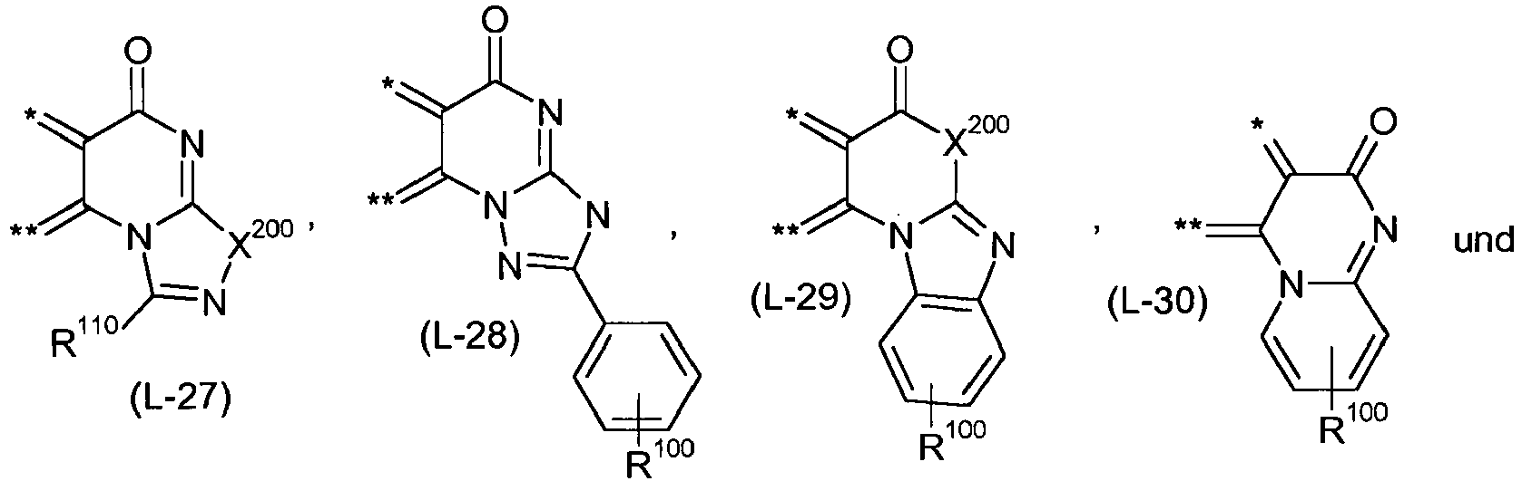

- R102
- Arylalkyl, Aryl oder Hetaryl,
- R112
- H, Alkyl, C1-C6-Alkylen-COO-Alkyl, C1-C6-Alkylen-O-CO-Alkyl, C1-C6- Alkylen-O-CO-O-Alkyl, Cylcloalkyl, Arylalkyl, Aryl, OR110 oder SR110,
- R113
- H, Alkyl, C1-C6-Alkylen-COO-Alkyl, C1-C6-Alkylen-O-CO-Alkyl, C1-C6- Alkylen-O-CO-O-Alkyl, Cylcloalkyl, Arylalkyl, Aryl, Hetaryl, NH-Aryl, N(Aryl)2, NHCO-R101 oder N(CO-R101)2,
- R114
- H, Alkyl oder teil- oder perfluoriertes Alkyl, C1-C6-Alkylen-COO-Alkyl, C1-C6-Alkylen-O-CO-Alkyl oder C1-C6- Alkylen-O-CO-O-Alkyl,
- R115
- H, Alkyl, teil- oder perfluoriertes Alkyl, C1-C6-Alkylen-COO-Alkyl, C1-C6-Alkylen-O-CO-Alkyl, C1-C6- Alkylen-O-CO-O-Alkyl, Cylcloalkyl, Arylalkyl, Aryl, NHCO-R101 oder N(CO-R101)2,
- R116
- H, Alkyl, C1-C6-Alkylen-COO-Alkyl, C1-C6-Alkylen-O-CO-Alkyl, C1-C6- Alkylen-O-CO-O-Alkyl, Cylcloalkyl, Arylalkyl, Aryl, CO2R110 oder CN
- R117
- H, Alkyl, C1-C6-Alkylen-COO-Alkyl, C1-C6-Alkylen-O-CO-Alkyl, C1-C6- Alkylen-O-CO-O-Alkyl, Cylcloalkyl, Arylalkyl, Aryl, OR110, SR110 Halogen oder Hetaryl,
- R212
- H, CN, CONR110 oder COR101,
- X202
- zweimal H, O oder S,
- Weitere bevorzugt zu verwendenden Mischungen, auch unter Berücksichtigung der zuvor beschriebenen Bevorzugungen, zeichnen sich dadurch aus, dass es sich bei Komponente K2 um ein oder mehrere Verbindungen ausgewählt aus der Gruppe
- a) Fullerene und Fullerenderivate,
- b) polycyclische aromatische Kohlenwasserstoffe und deren Derivate, insbesondere Naphthalin und dessen Derivate, Rylene, insbesondere Perylen, Terrylen und Quaterrylen, und deren Derivate, Azene, insbesondere Anthrazen, Tetrazen, in besondere Rubren, Pentazen und deren Derivate, Pyren und dessen Derivate, Coronen und Hexabenzocoronen und deren Derivate,
- c) Chinone, Chinondimethane und Chinondiimine und deren Derivate,
- d) Phthalocyanine und Subphthalocyanine und deren Derivate,
- e) Porphyrine, Tetraazaporphyrine und Tetrabenzoporphyrine und deren Derivate,
- f) Thiophene, oligo-Thiophene, kondensierte/anellierte Thiophene, wie Thienothiophen und Bithienothiophen, und deren Derivate,
- g) Thiadiazole und deren Derivate,
- h) Carbazole und Triarylamine und deren Derivate,
- i) Indanthrone, Violanthrone und Flavanthone und deren Derivate,
- j) Fulvalene, Tetrathiafulvalene und Tetraselenafulvalene und deren Derivate und
- k) Diketopyrrolopyrrole und deren Derivate
- Insbesondere finden erfindungsgemäße Verwendung, auch unter Berücksichtigung der zuvor beschriebenen Bevorzugungen, Mischungen, welche sich dadurch auszeichnen, dass es sich bei Komponente K2 um ein oder mehrere Fullerene und/oder Fulleren-Derivate handelt.
- Als leicht zugängliche Fulleren-Derivate kommen insbesondere Verbindungen der allgemeinen Formel k2

worin bedeuten - Q
- C1-C10-Alkylen,
- R'
- Aryl oder Arylalkyl
und - R"
- Alkyl.
- Zur Definition von Aryl, Arylalkyl und Alkyl wird auf das bereits zuvor Gesagte verwiesen.
Unter C1-C10-Alkylen ist insbesondere eine lineare Kette -(CH2)m-, mit m gleich 1, 2, 3, 4, 5, 6, 7, 8, 9 oder 10, zu verstehen. - Insbesondere finden erfindungsgemäß solche Fulleren-Derivate Verwendung, in welchen R' einen C1-C4-Alkyl-, insbesondere einen Methylrest, bezeichnet, Q für eine Propylen-Kette -(CH2)3- und R" für ein gegebenenfalls substituiertes Phenyl oder 2-Thienyl steht. Vorzugsweise handelt es sich bei dem Fulleren-Derivat um [6,6]-Phenyl-C61-butylsäuremethylester ("PCBM").
- Besonders bevorzugt kommen zur Verwendung, auch unter Berücksichtigung der zuvor genannten Bevorzugungen, Mischungen, in welchen es sich bei Komponente K2 um ein oder mehrere Fullerene handelt.
- Als mögliche Fullerene sind zu nennen C60, C70, C76, C80, C82, C84, C86, C90 und C94, insbesondere das C60 und C70. Einen Überblick über Fullerene, welche erfindungsgemäß verwendet werden können, liefert beispielsweise die Monografie von A. Hirsch, M. Brettreich, "Fullerenes: Chemistry and Reactions", Wiley-VCH, Weinheim 2005.
- Insbesondere handelt es sich bei Komponente K2 um ein C60-Fulleren der Formel k2

- Die erfindungsgemäß zu verwendenden Mischungen zeichnen sich dadurch aus, dass die Komponente K1 in einem Anteil von 10 bis 90 Massen-%, insbesondere 20 bis 80 Massen-%, und die Komponente K2 in einem Anteil von 90 bis 10 Massen-%, insbesondere 80 bis 20 Massen-%, vorliegt, wobei sich die Anteile der Komponenten K1 und K2, jeweils bezogen auf die Gesamtmasse der Komponenten K1 und K2, zu 100 Massen-% ergänzen.
- Herstellungsbedingt ist es im Einzelfall möglich, dass nicht eine explizit gezeigte Verbindung der Formel Ia, sondern eine dazu isomere Verbindung erhalten wird oder dass auch Mischungen von Isomeren erhalten werden. Erfindungsgemäß sollen dementsprechend auch die isomeren Verbindungen der Formel la und die Isomeren der entsprechenden bevorzugten Verbindungen sowie Mischungen von Isomeren umfasst sein.
- Die Synthese der Verbindungen der allgemeinen Formel la sind dem Fachmann bekannt oder lassen sich in Anlehnung an bekannte Syntheseverfahren herstellen. Beispielsweise sind hinsichtlich entsprechender Synthesen die nachfolgenden Publikationen zu nennen:
-
DE 195 02 702 A1 ,EP 416 434 A2 EP 509 302 A1 EP 291 853 A2 US 5,147,845 ,US 5,703,238 ; - "ATOP Dyes. Optimization of a Multifunctional Merocyanine Chromophore for High Refractive Index Modulation in Photorefractive Materials", F. Würthner, S. Yao, J. Schilling, R. Wortmann, M. Redi- Abshiro, E. Mecher, F. Gallego-Gomez, K. Meerholz, J. Am. Chem. Soc. 2001, 123, 2810 - 2814;
- "Merocyaninfarbstoffe im Cyaninlimit: eine neue Chromophorklasse für photorefraktive Materialien; Merocyanine Dyes in the Cyanine Limit: A New Class of Chromophores for Photorefractive Materials", F. Würthner, R. Wortmann, R. Matschiner, K. Lukaszuk, K. Meerholz, Y. De Nardin, R. Bittner, C. Bräuchle, R. Sens , Angew. Chem. 1997, 109, 2933 - 2936; Angew. Chem. Int. Ed. Engl. 1997, 36, 2765 - 2768;
- "Electrooptical Chromophores for Nonlinear Optical and Photorefractive Applications", S. Beckmann, K.-H. Etzbach, P. Krämer, K. Lukaszuk, R. Matschiner, A. J. Schmidt, P. Schuhmacher, R. Sens, G. Seybold, R. Wortmann, F. Würthner, Adv. Mater. 1999, 11, 536 - 541;
- "DMF in Acetic Anhydride: A Useful Reagent for Multiple- Component Syntheses of Merocyanine Dyes", F. Würthner, Synthesis 1999, 2103 - 2113;
- Ullmanns' Encyclopedia of industrial Chemistry, Vol. 16, 5th Edition (Ed. B. Elvers, S. Hawkins, G. Schulz), VCH 1990 im Kapitel "Methine Dyes and Pigments", S. 487 - 535 von R. Raue (Bayer AG).
- Insbesondere sind die Publikationen zu nennen:
- T. Zimmermann, J. Heterocycl. Chem., 2000, 37,1571; (Verbindungen la)
- T. Zimmermann and O. Brede, J. Heterocycl. Chem., 2004, 41, 103; (Verbindungen la)
- Nachfolgend seien exemplarisch erfindungsgemäß verwendbare Verbindungen der allgemeinen Formel la gezeigt:


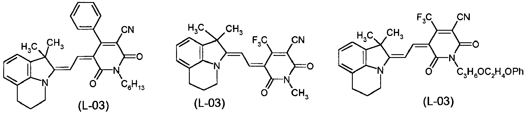
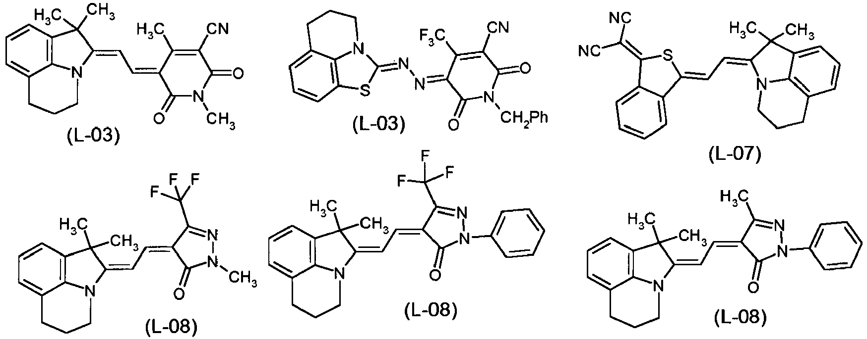


- Verbindungen der Formel la, in welchen die Einheit L fehlt (n = 0), sind exemplarisch nachfolgend gezeigt:

- Weiter wird im Rahmen der vorliegenden Erfindung unter anderem ein Verfahren zur Herstellung von photoaktiven Schichten beansprucht, welches dadurch gekennzeichnet ist, dass ein oder mehrere der eingangs gezeigten Verbindungen der allgemeinen Formel la der Komponente K1, auch unter Berücksichtigung ihrer Bevorzugungen, und ein oder mehrere Verbindungen der Komponente K2, ebenfalls unter Berücksichtigung ihrer Bevorzugungen, gleichzeitig, nacheinander oder in alternierender Abfolge durch Vakuumsublimation auf einem Substrat abgeschieden werden.
- Insbesondere zeichnet das Verfahren aus, dass sich die Komponente K1 in einem Anteil von 10 bis 90 Massen-%, insbesondere 20 bis 80 Massen-%, und die Komponente K2 in einem Anteil von 90 bis 10 Massen-%, insbesondere 80 bis 20 Massen-%, auf dem Substrat abgeschieden befindet, wobei sich die Anteile der Komponenten K1 und K2, jeweils bezogen auf die Gesamtmasse der Komponenten K1 und K2, zu 100 Massen-% ergänzen.
- Weiter werden im Rahmen der vorliegenden Erfindung organische Solarzellen und organische Photodetektoren beansprucht, welche photoaktive Schichten enthalten, die unter Verwendung der zuvor beschriebenen, die Komponenten K1 und K2 enthaltenden Mischungen, oder unter Verwendung der ebenfalls zuvor beschriebenen bevorzugten Ausführungsformen der Mischungen hergestellt worden sind.
- Organische Solarzellen sind meist schichtförmig aufgebaut und umfassen in der Regel zumindest die folgenden Schichten: Elektrode, photoaktive Schicht und Gegenelektrode. Diese Schichten befinden sich in der Regel auf einem dafür üblichen Substrat. Geeignete Substrate sind z.B. oxidische Materialien, wie etwa Glas, Quarz, Keramik, SiO2, etc., Polymere, wie etwa Polyvinylchlorid, Polyolefine, z.B. Polyethylen und Polypropylen, Polyester, Fluorpolymere, Polyamide, Polyurethane, Polyalkyl(meth)-acrylate, Polystyrol und Mischungen und Komposite davon, und Kombinationen der zuvor aufgeführten Substrate.
- Als Materialien für die eine Elektrode eignen sich insbesondere Metalle, wie z.B. die Alkalimetalle Li, Na, K, Rb und Cs, die Erdalkalimetalle Mg, Ca und Ba, Pt, Au, Ag, Cu, Al, In, Metalllegierungen, z.B. auf Basis Pt, Au, Ag, Cu, etc. und spezielle Mg/Ag-Legierungen, des weiteren aber auch Alkalimetallfluoride, wie LiF, NaF, KF, RbF und CsF, und Mischungen aus Alkalimetallfluoriden und Alkalimetallen. Bevorzugt wird als Elektrode ein das einfallende Licht im Wesentlichen reflektierendes Material eingesetzt. Dazu zählen beispielsweise Metallfilme aus Al, Ag, Au, In, Mg, Mg/Al, Ca, etc.
- Die Gegenelektrode besteht aus einem, gegenüber einfallendem Licht im Wesentlichen transparenten Material, z. B. ITO, dotiertes ITO, ZnO, TiO2, Cu, Ag, Au und Pt, wobei die letztgenannten Metalle in entsprechend dünnen Schichten vorliegen.
- Als "transparent" soll hierbei eine Elektrode/Gegenelektrode angesehen werden, wenn mindestens 50 % der Strahlungsintensität in dem Wellenlängen-Bereich transmittiert wird, in welchem die photoaktive Schicht Strahlung absorbiert. Im Falle mehrerer photoaktiver Schichten soll eine Elektrode/Gegenelektrode als "transparent" angesehen werden, wenn mindestens 50 % der Strahlungsintensität in den WellenlängenBereichen transmittiert wird, in welchen die photoaktiven Schichten Strahlung absorbieren.
- Zusätzlich zur photoaktiven Schicht können eine oder mehrere weitere Schichten in den erfindungsgemäßen organischen Solarzellen und Photodetektoren vorhanden sein, z.B. Elektronen transportierende Schichten ("ETL", electron transporting layers) und/oder Löcher transportierende Schichten ("HTL", hole transporting layers) und/oder blockierende Schichten, z.B. Excitonen blockierende Schichten ("EBL", excition blocking layers), die üblicherweise das einfallende Licht nicht absorbieren, oder auch Schichten, welche als Ladungstransportschichten dienen und gleichzeitig die Kontaktierung zu einer oder beiden Elektroden der Solarzelle verbessern. Die ETL und HTL können auch dotiert sein, so dass sich Zellen vom p-i-n-Typ ergeben, wie sie beispielsweise in der Publikation von J. Drechsel et al., Thin Solid Films 451 - 452 (2004), 515 - 517, beschrieben sind.
- Übliche Aufbauten A), B) und C) von Solarzellen sind nachfolgend beschrieben:
- A) Zweischichtaufbau:
- Der Aufbau umfasst folgende Schichten:
- 16
- Metallelektrode (Kathode)
- (15
- optionale EBL und/oder ETL)
- 14
- Elektronenakzeptor-Schicht
- 13
- Elektronendonor-Schicht
- (12
- optionale HTL)
- 11
- Transparente Elektrode (Anode)
- Der Aufbau umfasst folgende Schichten:
- Bei Schicht 11 handelt es sich um eine transparente, leitfähige Schicht, beispielsweise ITO, FTO oder ZnO, welche gegebenenfalls z.B. mit Sauerstoffplasma, UV/Ozon-Spülung etc. vorbehandelt ist. Diese Schicht muss einerseits so dünn sein, dass nur geringe Lichtabsorption auftritt, jedoch andererseits dick genug, um einen zufriedenstellenden lateralen Ladungstransport innerhalb der Schicht zu gewährleisten. Üblicherweise beträgt die Dicke der Schicht 20 - 200 nm und sie wird auf einem Substrat wie Glas oder einem flexiblen Polymer (beispielsweise PET) aufgebracht.
- Schicht 12 besteht aus einer oder mehreren HTLs mit einem hohen lonisierungspotential (> 5,0 eV, vorzugsweise 5,5 eV). Diese Schicht kann entweder aus organischem Material bestehen, wie Poly(3,4-ethylendioxythiophen) mit Poly(styrolsulfonat)(PEDOT-PSS) dotiert, oder beispielsweise aus Ir-DPBIC (Tris-N,N'-Diphenylbenzimidazol-2-yliden-iridium(III)), N,N'-Diphenyl-N,N'-bis (3-methylphenyl)-1,1'-diphenyl-4, 4'-diamin (α-NPD) und/oder 2,2',7,7'-Tetrakis(N,N-di-p-methoxyphenylamin)-9,9'-spirobifluoren (spiro-MeOTAD), oder aus anorganischem Material, wie WO3, MoO3, usw. Üblicherweise beträgt die Schichtdicke 0 - 150 nm. Für den Fall, dass Schicht 12 aus organischem Material aufgebaut ist, kann sie mit einem p-Dotierstoff versetzt werden, dessen LUMO-Energie im gleichen oder niedrigeren Energiebereich liegt wie das HOMO der HTL. Solche Dotierstoffe sind beispielsweise 2,3,5,6-Tetrafluoro-7,7,8,8-tetracyano-quinodimethan (F4TCNQ), WO3, MoO3, oder die in der Schrift
WO 2007/071450 A1 beschriebenen Substanzen. - Schicht 13 besteht aus dem Elektronendonor. Üblicherweise sollte die Schicht so dick sein, dass sie möglichst viel Licht absorbiert, andererseits aber ausreichend dünn, um die gebildeten Ladungen effektiv abführen zu können. In der Regel beträgt die Dicke 5 - 200 nm.
- Schicht 14 besteht aus dem Elektronenakzeptor. Wie für Schicht 13 sollte auch hier die Dicke ausreichend sein, um so viel Licht wie möglich zu absorbieren, andererseits müssen jedoch die gebildeten Ladungen effektiv abgeleitet werden. Üblicherweise weist diese Schicht ebenfalls eine Dicke 5 - 200 nm auf.
- Schicht 15 ist eine EBL/ETL und sollte eine größere optische Bandlücke aufweisen als die Materialien der Schicht 14, um die Exitonen zu reflektieren, trotzdem jedoch noch über ausreichende Elektronentransporteigenschaften verfügen. Geeignete Verbindungen sind 2,9-Dimethyl-4,7-diphenyl-1,10-phenanthrolin (BCP), 4,7-Diphenyl-1,10-phenanthrolin (Bphen), 1,3-Bis[2-(2,2'-bipyridin-6-yl)1,3,4-oxadizo-5-yl]benzol (BPY-OXD), ZnO,TiO2 etc. Für den Fall einer organischen Schicht kann diese mit einem n-Dotierstoff versehen werden, dessen HOMO ähnliche oder geringere Energie besitzt, als das LUMO der Elektronen transportierenden Schicht. Geeignete Materialien sind Cs2CO3, Pyronin B (PyB), beschrieben beispielsweise in der Schrift
WO 2003/070822 A2 , Rodamine B, beschrieben beispielsweise in der SchriftWO 2005/036667 A1 , Cobaltocen und die in der SchriftWO 2007/071450 A1 erwähnten Verbindungen. Die Schichtdicke beträgt üblicherweise 0-150 nm. - Schicht 16 (Kathode) besteht aus einem Material mit geringer Austrittsarbeit. Beispielsweise handelt es sich hier um Metalle wie Ag, Al, Ca, Mg oder deren Mischungen. Die Schichtdicke beträgt üblicherweise 50-1000 nm und sollte so ausreichend gewählt werden, dass das meiste Licht im Wellenlängenbereich von 350 - 1200 nm reflektiert wird.
- Die üblichen Drücke während der Gasphasenabscheidung liegen zwischen 10-4 und 10-9 mbar. Die Abscheidungsrate variiert in der Regel zwischen 0,01 nm/Sekunde und 10 nm/Sekunde. Die Temperatur des Substrats während der Abscheidung kann man in einem Temperaturbereich zwischen -100 °C und 200 °C variieren, um die Morphologie der entsprechenden Schicht gezielt zu beeinflussen. Die Abscheidungsrate liegt üblicherweise zwischen 0,1 nm/Sekunde und 2,0 nm/Sekunde.
- Für die Abscheidung der Schichten kann ebenfalls das in
WO 1999/025894 A1 beschriebene Verfahren eingesetzt werden. - Nach dem Abscheiden der aktiven Schicht (Schicht 13 und 14) oder nach dem Fertigstellen der gesamten Zelle, d.h. nach dem Abscheiden von Schicht 16, kann sich eine Temperung bei 60 °C bis 100 °C für die Dauer von wenigen Minuten bis hin zu einigen Stunden anschließen, um einen innigeren Kontakt der Schichten zu erreichen. Ebenso kann zu diesem Zweck eine Behandlung mit Lösungsmitteldampf , beispielsweise von Toluol, Xylol, Chloroform, N-Methylpyrrolidon, Dimethylformamid, Ethylacetat, Chlorbenzol und Dichlormethan oder anderen Lösungsmitteln für die entsprechende Dauer vorgenommen werden.
- B) Bulk-Heterojunction-(BHJ)-Aufbau:
- Der Aufbau umfasst folgende Schichten:
- 26
- Metallelektrode (Kathode)
- (25
- optionale EBL und/oder ETL)
- 24
- ETL
- 23
- Elektronenakzeptor-Elektronendonor-Schicht
- (22
- optionale HTL)
- 21
- Transparente Elektrode (Anode)
- Der Aufbau umfasst folgende Schichten:
- Die Schichten 21 und 22 entsprechen den Schichten 11 und 12 aus Aufbau A).
- Die Schicht 23 kann durch gemeinsames Verdampfen oder durch Lösungsprozessierung mit üblichen Lösungsmitteln hergestellt werden - hierauf wird weiter unten eingegangen - hergestellt werden. Der Anteil des Elektronendonors beträgt in beiden Fällen vorzugsweise 10 bis 90 Massen-%, insbesondere 20 bis 80 Massen-%. Der Anteil an Elektronenakzeptor ergibt sich ergänzend zu 100 Massen-%. Auch hier muss die Schicht so dick sein, dass ausreichend Licht absorbiert wird, jedoch immer noch so dünn, dass die Ladungsträger effektiv abgeführt werden können. Üblicherweise ist die Schicht 5 - 500 nm dick.
- Die ETL-Schicht 24 kann aus ein oder mehreren Schichten von Materialien mit einer geringen LUMO-Energie (<3,5 eV) bestehen. Diese Schichten können entweder aus organischen Verbindungen, wie C60-Fulleren, BCP, Bphen oder BPY-OXD, oder aus anorganischen Verbindungen, wie ZnO, TiO2 etc. bestehen und sind in der Regel zwischen 0 nm - 150 nm dick. Im Falle von organischen Schichten können diese mit den bereits oben erwähnten Dotierstoffen versetzt sein.
- Die Schichten 25 und 26 entsprechen den Schichten 15 und 16 aus Aufbau A). Ebenso entsprechen die Abscheidungsraten und Nachbehandlungen denjenigen aus Aufbau A).
- Der Aufbau umfasst folgende Schichten:
- 36
- Metallelektrode (Kathode)
(zusätzliche Rekombinationsschichten und Subzellen) - 34
- 2. Subzelle
- 33
- Rekombinationsschicht
- 32
- 1. Subzelle
- 31
- Transparente Elektrode (Anode)
- Tandemzellen enthalten zwei oder mehrere Subzellen, die meist in Serie geschaltet sind, wobei zwischen den einzelnen Subzellen Rekombinationsschichten angeordnet sind.
- Schicht 31 entspricht vom Aufbau den zuvor genannten Schichten 11 und 21 aus Aufbau A) und B).
- Die Schichten 32 und 34 sind individuelle Subzellen und entsprechen in ihrer Funktion einzelnen Zellen wie unter Aufbau A) und B) mit dem Unterschied, dass sie keine Elektroden 11/16 bzw. 21/26 enthalten. Die Subzellen bestehen daher aus den Schichten 12 bis 15 des Aufbaus A) bzw. 22 bis 25 des Aufbaus B).
- Die Subzellen können als Komponente K1 bzw. K2 entweder alle Merocyanine enthalten oder eine Subzelle enthält ein oder mehrere Merocyanine und die übrigen Subzellen enthalten Kombinationen anderer Materialien, wie beispielsweise C60-Fulleren/Zn-Phthalocyanin, Oligothiophen (beispielsweise DCV5T)/C60-Fulleren (wie in
WO 2006/092134 A1 beschrieben), oder eine der Subzellen ist eine Farbstoffsensibilisierte Solarzelle (DSSC) oder eine Polymerzelle, wie beispielsweise in der Kombination P3HT/PCBM. Des Weiteren können sowohl Zellen vom Aufbau A) als auch vom Aufbau B) als Subzellen enthalten sein. In den genannten Fällen ist es am günstigsten, wenn die Kombination der Materialien/Subzellen so gewählt wird, dass die Lichtabsorptionen der Subzellen nicht zu stark überlappen, sondern in Summe das Spektrum des Sonnenlichts abdecken, was zu einer Erhöhung der Stromausbeute führt. Unter Berücksichtigung von optischen Interferenzen, welche in der Zelle stattfinden, ist es zudem sinnvoll, eine Subzelle mit Absorption im kürzeren Wällenlängenbereich näher an der Elektrode 36 zu plazieren, als eine Subzelle mit Absorption im längeren Wellenlängenbereich. - Durch die Rekombinationsschicht 33 wird die Rekombination entgegengesetzt geladenen Ladungsträger in benachbarten Subzellen bewirkt. Als wirksame Bestandteile in der Rekombinationsschicht können Metallcluster, beispielsweise aus Ag oder Au, wirken oder die Rekombinationsschicht besteht aus einer Kombination hochdotierter n- und p-leitenden Schichten (wie beispielsweise in
WO 2004/083958 A2 beschrieben). Im Fall der Verwendung von Metallclustern werden üblicherweise Schichtdicken von 0,5 - 20 nm, im Fall der kombinierten dotierten Schichten Dicken von 5 - 150 nm eingestellt. Weitere Subzellen können auf die Subzelle 34 aufgebracht werden, wobei dann ebenfalls weitere Rekombinationsschichten, wie Schicht 33, vorhanden sein müssen. - Das Material für die Elektrode 36 hängt von der Polarität der Subzellen ab. Bei normaler Polarität kommen die bereits erwähnten Metalle mit geringer Austrittsarbeit, wie beispielsweiese Ag, Al, Mg und Ca, in Betracht. Bei invertierter Polarität verwendet man üblicherweise Materialien mit hoher Austrittsarbeit, wie beispielsweise Au, Pt, PEDOT-PSS.
- Bei Tandemzellen, welche in Serie geschaltete Subzellen enthalten, addieren sich die Teilspannungen, der Gesamtstrom ist aber durch die Subzelle mit der geringsten Stromstärke/Stromdichte limitiert. Daher sollten die einzelnen Subzellen so optimiert werden, dass deren indiviuellen Stromstärken/Stromdichten ähnliche Werte aufweisen.
- Der Aufbau organischer Solarzellen ist des Weiteren z.B. in den Schriften
WO 2004/083958 A2 ,US 2005/0098726 A1 undUS 2005/0224905 A1 beschrieben, worauf hier in vollem Umfang Bezug genommen wird. - Photodetektoren besitzen im Wesentlichen einen zu organischen Solarzellen analogen Aufbau, sie werden jedoch mit geeigneter Vorspannung betrieben, welche bei Einwirkung von Strahlungsenergie einen entsprechenden Stromfluss als Messantwort generiert.
- Die Prozessierung der photoaktiven Schichten kann aus Lösung erfolgen. Hierbei können die Komponenten K1 und K2 bereits gemeinsam gelöst, aber auch separat als Lösung der Komponente K1 und Lösung der Komponente K2 vorliegen, wobei die Vermischung der entsprechenden Lösungen in letzterem Fall kurz vor der Aufbringung auf die darunterliegende Schicht erfolgt. Die Konzentrationen der Komponenten K1 und K2 belaufen sich in der Regel auf etwa einige g/l bis einige zehn g/l Lösungsmittel.
- Als Lösungsmittel eignen sich alle Flüssigkeiten, welche rückstandsfrei verdampfen und eine ausreichende Löslichkeit für die Komponenten K1 und K2 aufweisen. Hier kommen beispielsweise in Frage aromatische Verbindungen, wie etwa Benzol, Toluol, Xylol, Mesitylen, Chlorbenzol oder Dichlorbenzol, Trialkylamine, stickstoffhaltige Heterocyclen, N,N-disubstituierte aliphatische Carbonsäureamide, wie etwa Dimethylformamid, Diethylformamid, Dimethylacetamid oder Dimethylbutyramid, N-Alkyllactame, wie etwa N-Methylpyrrolidon, lineare und cyclische Ketone, wie etwa Methylethylketon, Cyclopentanon oder Cyclohexanon, cyclische Ether, wie etwa Tetrahydrofuran, oder Alkohole, wie etwa Methanol, Ethanol, Propanol, Isopropanol oder Butanol.
- Desweiteren können auch Mischungen der vorgenannten Lösungsmittel Verwendung finden.
- Geeignete Methoden zur Aufbringung der erfindungsgemäßen photoaktiven Schichten aus flüssiger Phase sind dem Fachmann bekannt. Vorteilhaft zeigt sich hier insbesondere die Prozessierung mittels Spin-Coating, da die Dicke der photoaktiven Schicht in einfacher Weise durch die Menge und/oder Konzentration der verwendeten Lösung sowie die Rotationsgeschwindigkeit und/oder Rotationsdauer gesteuert werden kann. Die Prozessierung der Lösung erfolgt in der Regel bei Raumtemperatur.
- Vorzugsweise werden die Komponenten K1 und K2 aber aus der Gasphase, insbesondere durch Vakuumsublimation, abgeschieden. Da die Verbindungen der Formel la in der Regel durch Sublimation gereinigt werden können, lassen sich daraus bereits Startparameter für die Gasphasenabscheidung ableiten. Üblicherweise werden für die Abscheidung Temperaturen zwischen 100 und 200 °C angewendet, sie können aber auch, je nach Stabilität der Verbindungen der Komponenten K1 und K2 auch bis in einen Bereich von 300 bis 400 °C erhöht werden.
- Im Rahmen der vorliegenden Erfindung werden auch Mischungen beansprucht, welche als Komponenten ein oder mehrere der eingangs gezeigten Verbindungen der allgemeinen Formel la der Komponente K1, auch unter Berücksichtigung der aufgeführten Bevorzugungen, und ein oder mehrere Verbindungen der Komponente K2, ebenfalls unter Berücksichtigung ihrer aufgeführten Bevorzugungen, enthalten.
- Insbesondere zeichnen sich die erfindungsgemäßen Mischungen dadurch aus, dass die Komponente K1 in einem Anteil von 10 bis 90 Massen-%, insbesondere 20 bis 80 Massen-%, und die Komponente K2 in einem Anteil von 90 bis 10 Massen-%, insbesondere 80 bis 20 Massen-%, vorliegt, wobei sich die Anteile der Komponenten K1 und K2, jeweils bezogen auf die Gesamtmasse der Komponenten K1 und K2, zu 100 Massen-% ergänzen.
- Nachfolgend wird die Erfindung anhand der nicht als Einschränkung des Erfindungsumfangs zu verstehenden Beispiele näher erläutert.
- Verbindungen la-1 bis la-4 entsprechend der allgemeinen Formel la:

- Allgemeines Syntheseschema:
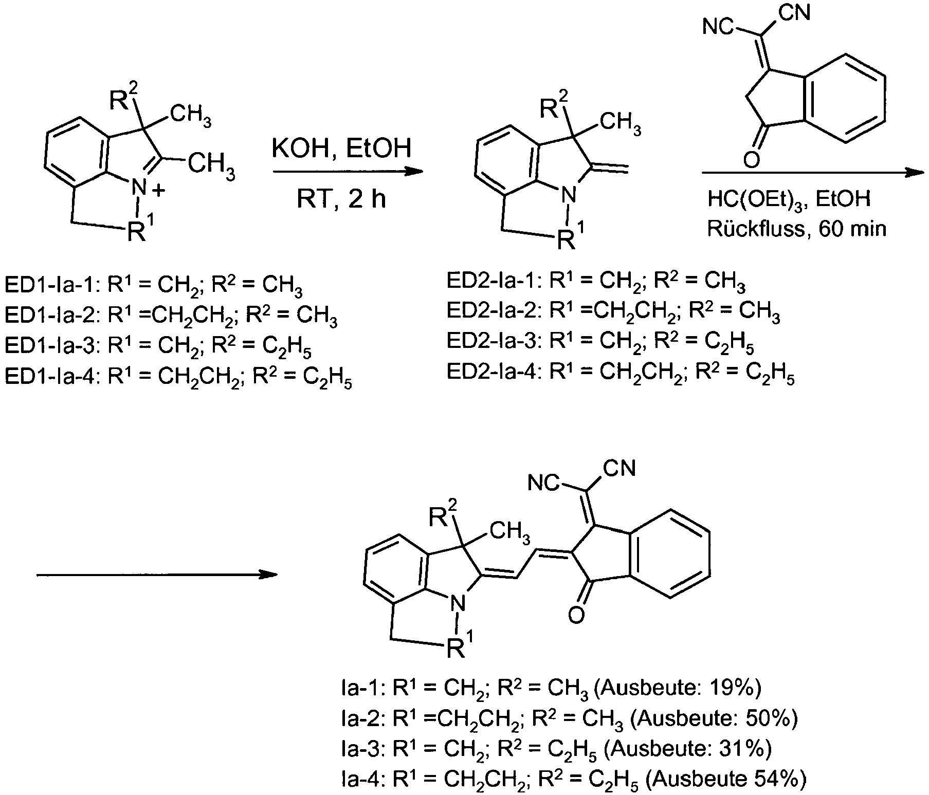
- Allgemeine Vorschrift zur Herstellung der Verbindungen ED2-Ia-1 bis ED2-Ia-4:
- 1 Equivalent des entsprechenden Salzes ED1-Ia-1 bis ED1-Ia-4 in 15-20 Equivalenten trockenem Ethanol (EtOH) wurde mit 1,1 Equivalenten KOH versetzt. Die Lösung wurde 3 h bei Raumtemperatur gerührt, bevor das Lösungsmittel unter Vakuum entfernt wurde. Nach Zugabe von Wasser wurde mit Diethylether ausgeschüttelt. Nach erneutem Entfernen des Lösungsmittels unter Vakuum wurde ein Öl erhalten, welches direkt weiter umgesetzt wurde.
- 1,1-Dimethyl-2-methylen-1,2,4,5-tetrahydro-pyrrolo[3,2,1-hi]-indol (ED2-Ia-1) Ausbeute: 520 mg, 77%. 1H NMR (CDCl3, 400 MHz): δ = 6,93 (m, 1H), 6,87 (m,1 H), 6,63 (m, 1 H), 3,95 (d, 2 J = 1,6 Hz, 1 H), 3,87 (d, 2 J = 1,6 Hz, 1 H), 3,65 (m, 2H), 3,41 (m, 2H), 1,42 (s, 6H). HRMS (ESI): ber. für C13H16N [M+H]+: 186,1277, gef.: 186,1277.
- 1,1-Dimethyl-2-methylen-1,2,4,5-tetrahydro-pyrrolo[3,2,1-hi]-quinolin (ED2-Ia-2) Ausbeute: 4,33 g, 42%. 1H NMR (CDCl3, 400 MHz): δ = 6,94 (m, 1H), 6,87 (m,1H), 6,67 (m, 1 H), 3,81 (d, 2 J = 1,6 Hz, 1 H), 3,79 (d, 2 J = 1,6 Hz, 1 H), 3,40 (t, 3 J = 5,8 Hz, 2H), 2,73 (m, 2H), 2,04 (m, 2H), 1,37 (s, 6H). HRMS (ESI): ber. für C14H18N [M+H]+: 200,1434, gef.: 200,1434.
- 1-Ethyl-1-methyl-2-methylen-1,2,4,5-tetrahydro-pyrrolo[3,2,1-hi]-indol (ED2-Ia-3) Ausbeute: 276 mg, 84%. 1H NMR (CDCl3, 400 MHz, TMS): δ = 6,91 (m, 1 H), 6,83 (m, 1 H), 6,62 (m, 1 H), 3,91 (d, 2 J = 0,7 Hz, 1 H), 3,88 (d, 2 J = 0,7 Hz, 1 H), 3,54 (m, 2H), 2,96 (t, J = 6,1 Hz, 2H), 1,78 (m, 2H), 1,36 (s, 3H), 0,76 (t, J = 7,3 Hz, 3H). HRMS (ESI): ber. für C14H18N [M+H]+: 200,1434, gef.: 200,1434.
- 1-Ethyl-1-methyl-2-methylen-1,2,4,5-tetrahydro-pyrrolo[3,2,1-hi]-quinolin (ED2-Ia-4) Ausbeute: 590 mg, 97%. 1H NMR (CDCl3, 400 MHz, TMS): δ = 6,87 (m, 1H), 6,81 (m, 1 H), 6,57 (m, 1 H), 3,83 (d, 2 J = 0,7 Hz, 1 H), 3,72 (d, 2 J = 0,7 Hz, 1 H), 3,32 (m, 2H), 2,65 (t, J = 6,1 Hz, 2H), 1,95 (m, 2H), 1,92 (m, 1 H), 1,57 (m, 1 H), 1,25 (s, 3H), 0,51 (t, J = 7,3 Hz, 3H). HRMS (ESI): ber. für C15H20N [M+H]+: 214,1590, gef.: 214,1590.
- Allgemeine Vorschrift zur Herstellung der Verbindungen la-1 bis la-4:
- 1 Equivalent ED2-Ia-1 bis ED2-Ia-4, 1 Equivalent 2-(3-Oxo-indan-1-yliden)-malononitril und 1,5 Equivalente Orthoameisensäuretriethylester in 1mL/ Equivalent Ethanol wurden 1 h unter Rückfluss erhitzt. Nach Entfernen des Lösungsmittels wurde das Produkt durch Säulenchromatographie (CH2Cl2) und Umfällen aus CH2Cl2/n-Hexan aufgereinigt.
- Ausbeute: 200 mg, 19%, brauner Feststoff. Smp 277°C. 1H NMR (CDCl3, 400 MHz): δ = 8,55 (d, 3 J = 14,0 Hz, 1 H), 8,34 (m, 1 H), 7,58-7,73 (m, 4H), 7,39 (m, 1 H), 7,31 (m, 1 H), 7,22 (t, 3 J = 7,3 Hz, 1 H), 4,64 (m, 2H), 3,77 (t, 3 J = 6,2 Hz, 2H), 1,65 (s, 6H). UV-vis (CH2Cl2): λmax (ε) = 486 (20300), 586 (51100 M-1 cm-1). HRMS (ESI): ber. für C26H20N3O [M+H]+: 390,1600, gef.: 390,1599.
- Ausbeute: 1,4 g, 50%, brauner Feststoff. Smp 291°C. 1H NMR (CDCl3, 400 MHz): δ = 9,00 (d, 3 J = 14,0 Hz, 1 H), 8,56 (m, 1 H), 7,92 (d, 3 J = 13,8 Hz, 1 H), 7,70 (m, 1 H), 7,58 (m, 2H), 7,15 (m, 3H), 4,05 (br, 2H), 2,90 (t, 3 J = 6,1 Hz, 2H), 2,25 (m, 2H), 1,79 (s, 6H). UV-vis (CH2Cl2): λmax(ε) = 482 (21700), 578 (60300 M-1 cm-1). HRMS (ESI): ber. für C27H21N3O [M]+: 403,1685, gef.: 403,1679.
- Ausbeute: 170 mg, 31%, brauner Feststoff. Smp 230 °C. 1H NMR (DMSO-d6, 400 MHz): δ 8,56 (d, 3 J = 14,1 Hz, 1 H), 8,34 (m, 1 H), 7,65 (m, 4H), 7,34 (m, 2H), 7,23 (m, 1 H), 4,67 (bs, 2H), 3,79 (m, 2H), 2,04 (m, 2H), 1,63 (s, 3H), 0,62 (t, 3 J = 7,4 Hz, 3H). UV-vis (CH2Cl2): λmax (ε) = 486 (17500), 588 (45000). HRMS (ESI): ber. für C27H21N3O [M]+: 403,1685, gef.: 403,1679.
- Ausbeute: 200 mg, 54%, dunkelroter Feststoff. Smp 255°C. 1H-NMR (CDCl3, 400 MHz): δ = 8,96 (d, 3 J = 13,9 Hz, 1 H), 8,54 (m, 1 H), 7,90 (d, 3 J = 13,9 Hz, 1 H), 7,70 (m, 1 H), 7,57 (m, 2H), 7,14 (m, 3H), 4,05 (bs, 2H), 2,90 (t, 3 J = 6,2 Hz, 2H), 2,40 (bs, 1 H), 2,22 (m, 3H), 1,78 (s, 3H), 0,53 (t, 3 J = 7,4 H, 3H). UV-vis (CH2Cl2): λmax(ε) = 481 (18900), 577 (50100 M-1 cm-1). HRMS (ESI): ber. für C28H23N3O [M]+: 417,1814, gef.: 417,1834.
- Verbindungen Ia-5 bis la-12 entsprechend der allgemeinen Formel Ia:


-


- Eine Lösung aus 1,5 mL Acetanhydrid (Ac2O), Verbindung ED2-Ia-5 (341 mg, 1,5 mmol) und Indandion 3 (219 mg, 1,5 mmol) wurde für 30 min auf 90°C erhitzt, bevor das Lösungsmittel unter Vakuum entfernt wurde. Nach der Säulenchromatographie (CH2Cl2) wurde der erhaltene Feststoff in CH2Cl2 gelöst und mit n-Hexan ausgefällt.
- Ausbeute: 440 mg (1,24 mmol, 83%), violetter Feststoff. Smp 245-248°C. 1H NMR (CDCl3, 400 MHz): δ 8,08 (d, 3 J = 14,2 Hz, 1 H), 7,77 (m, 2H), 7,60 (m, 2H), 7,37 (d, 3 J = 14,2 Hz, 1H), 7,15 (m, 1H), 7,06 (m, 2H), 3,93 (bm, 2H), 2,86 (t, 3 J = 6,1 Hz, 2H), 2,21 (m, 2H), 1,74 (s, 6H). UV/Vis (CH2Cl2): λmax(ε): 500 (111200 M-1 cm-1). HRMS (ESI): ber. für C24H21NO2 [M]+: 355,1572, gef.: 355,1567. Anal. ber. für C24H21NO2: C, 81,10; H, 5,96; N, 3,94. Gef.: C, 80,75; H, 5,96; N, 4,10.
- Eine Lösung aus 1,5 mL Ac2O, Verbindung ED2-Ia-5 (341 mg, 1,5 mmol) und dem Pyridonderivat (309 mg, 1,5 mmol) wurde für 30 min auf 90°C erhitzt, bevor das Lösungsmittel unter Vakuum entfernt wurde. Der Rückstand wurde in CH2Cl2 gelöst und mit n-Hexan ausgefällt, bevor eine Säulenchromatographie (CH2Cl2) durchgeführt wurde. Der erhaltene Feststoff wurde wieder in CH2Cl2 gelöst und mit n-Hexan ausgefällt. Ausbeute: 304 mg (0,73 mmol, 49%), roter Feststoff. Smp 247-249°C. 1H NMR (CDCl3, 400 MHz): δ 8,00 (d, 3 J = 14,0 Hz, 1 H), 7,87 (d, 3 J = 14,0 Hz, 1 H), 7,21 (m, 1 H), 7,16 (m, 2H), 4,03 (t, 3 J = 5,9 Hz, 2H), 3,99 (t, 3 J = 7,6 Hz, 2H), 2,90 (t, 3 J = 6,1 Hz, 2H), 2,51 (s, 3H), 2,23 (m, 2H), 1,72 (s, 6H), 1,63 (m, 2H), 1,39 (m, 2H), 0,94 (t, 3 J = 7,4 Hz, 3H). UV/Vis (CH2Cl2): λ max(ε): 529 (133500 M-1 cm-1). HRMS (ESI): ber. für C26H30N3O2 [M+H]+: 416,2333, gef.: 416,2335.
- Eine Lösung aus 7,0 mL EtOH, Verbindung ED2-Ia-7 (370 mg, 2,0 mmol), dem Indandionderivat (548 mg, 2,0 mmol) und Orthoameisensäuretriethylester (430 mg, 2,9 mmol) wurde 1 h unter Rückfluss erhitzt, bevor das Lösungsmittel unter Vakuum entfernt wurde. Nach der Säulenchromatographie (CH2Cl2) wurde der erhaltene Feststoff in CH2Cl2 gelöst und mit n-Hexan ausgefällt.
- Ausbeute: 97 mg (0,21 mmol, 10%), dunkelgrüner Feststoff. Smp 269-272°C. 1H NMR (CDCl3, 400 MHz): δ 8,43 (m, 1 H), 8,13 (bm, 1 H), 7,84 (m, 2H), 7,65 (m, 4H), 7,48 (m, 2H), 7,17 (m, 3H), 4,46 (t, 3 J = 6,9 Hz, 2H). 3,80 (t, 3 J = 6,9 Hz, 2H), 1,65 (s, 6H). UV/Vis (CH2Cl2): λmax (s): 669 (35400 M-1 cm-1). HRMS (ESI): ber. für C32H24NO3 [M+H]+: 470,1751, gef.: 470,1751.
- Eine Lösung aus 5,0 mL Ac2O, Verbindung ED2-Ia-7 (926 mg, 5 mmol), dem Pyridonderivat (1,03 g, 5 mmol) und Dimethylformamid (DMF; 550 mg, 7,5 mL) wurde 1 h auf 90°C erhitzt, bevor das Lösungsmittel unter Vakuum entfernt wurde. Der Rückstand wurde in CH2Cl2 gelöst und mit n-Hexan ausgefällt, bevor eine Säulenchromatographie (CH2Cl2: MeOH = 98 : 2) durchgeführt wurde. Der erhaltene Feststoff wurde wieder in CH2Cl2 gelöst und mit n-Hexan ausgefällt.
- Ausbeute: 666 mg (1,66 mmol, 33%), dunkelroter Feststoff. Smp 246-249°C. 1H NMR (DMSO-d6, 400 MHz): δ 7,78 (d, 3 J = 14,5 Hz, 1 H), 7,57 (d, 3 J = 14,5 Hz, 1 H), 7,39 (d, 3 J = 7,3 Hz, 1 H), 7,31 (d, 3 J = 6,9 Hz, 1 H), 7,21 (t, 3 J = 7,3 Hz, 1 H), 4,73 (m, 2H), 3,84 (t, 3 J = 7,4 Hz, 2H), 3,77 (t, 3 J = 6,8 Hz, 2H), 2,47 (s, 3H), 1,58 (s, 6H), 1,47 (m, 2H), 1,27 (m, 2H), 0,90 (t, 3 J = 7,4 Hz, 3H). UV/Vis (CH2Cl2): λ max(ε): 537 (117400 M-1 cm-1). HRMS (ESI): ber. für C25H28N3O2 [M+H]+: 402,2176, gef.: 402,2176. Anal. ber. für C25H27N3O2: C, 74,79; H, 6,78; N, 10,47. Gef.: C, 74,36; H, 6,73; N, 10,58.
- 1 Equivalent des Akzeptormoleküls und ein Equivalent des Donormoleküls ED2-Ia-5 in 1mL/Äquivalent Ac2O wurden 1 h auf 90°C erhitzt. Nachdem das Lösungsmittel entfernt worden war, wurde der ausgefallenen Feststoff mit n-Hexan und iso-Propanol gewaschen, wenn nötig mittels Säulenchromatographie aufgereinigt und das Produkt aus einem CH2Cl2/n-Hexan-Gemisch umgefällt.
- Ausbeute: 339 mg (0,70 mmol, 80%), brauner Feststoff. 1H NMR (CD2Cl2, 400 MHz): δ 8,51 (d, 3 J = 14,6 Hz, 1 H), 8,42 (m, 1 H), 7,85 (m, 3H), 7,67 (m, 2H), 7,59 (m, 2H), 7,43 (m, 2H), 7,22 (m, 1H), 7,17 (m, 1H), 4,12 (m, 2H), 2,91 (m, 2H), 2,26 (m, 2H), 1,70 (s, 6H). UV-vis (CH2Cl2): λ max(ε): 665 (46500 M-1 cm-1). HRMS (ESI): ber. für C33H26NO3 [M+H]+: 484,1907, gef. 484,1908.
- Ausbeute: 186 mg (0,50 mmol, 57%), roter Feststoff. 1H NMR (CD2Cl2, 400 MHz): δ 8,03 (m, 1 H), 7,91 (m, 1H), 7,23 (m, 1H), 7,16 (m, 2H), 4,03 (2H), 3,29 (s, 3H), 2,90 (m, 2H), 2,52 (s, 3H), 2,22 (m, 2H), 1,71 (s, 6H). UV-vis (CH2Cl2): λ max (ε): 529 (131600 M-1 cm-1). HRMS (ESI): ber. für C23H24N3O2 [M+H]+: 374,1863, gef. 374,1861.
- Laufmittel für die Säulenchromatographie: DCM mit 0,2% MeOH. Ausbeute: 235 mg (0,57 mmol, 64%), dunkelblauer Feststoff. 1H NMR (CD2Cl2, 400 MHz): δ 8,29 (d, 3J = 13,5 Hz, 1 H), 7,20 (m, 1H), 7,14 (m, 2H), 5,60 (d, 3J = 13,6 Hz, 1H), 3,90 (m, 2H), 2,88 (m, 2H), 2,22 (m, 2H), 1,68 (s, 6H), 1,54 (s, 9H). UV-vis (CH2Cl2): λ max(ε): 627 (146100 M-1 cm-1). HRMS (ESI): ber. für C25H26N4S [M]+: 414,1878, gef. 414,1873.
- Laufmittel für die Säulenchromatographie: DCM mit 0,3% MeOH.
- Ausbeute: 267 mg (0,61 mmol, 70%), grünblauer Feststoff. 1H NMR (CD2Cl2, 400 MHz): δ 7,99 (d, 3J = 13,7 Hz, 1 H), 7,73 (m, 2H), 7,59 (m, 3H), 7,17 (m, 3H), 5,83 (d, 3J = 13,1 Hz, 1H), 3,96 (m, 2H), 2,89 (m, 2H), 2,23 (m, 2H), 1,55 (s, 6H). UV-vis (CH2Cl2): λ max (e): 635 (123200 M-1 cm-1). HRMS (ESI): ber. für C27H22N4S [M]+: 434,1565, gef. 434,1559.
- Alle aufgeführten Solarzellen wurden gemäß den nachfolgenden Schritten hergestellt: Sublimation der Merocyanine:
- Die eingangs aufgeführten Materialien wurden durch Zonensublimation gereinigt, wobei der Druck während der gesamten Sublimation unter 1 x10⁻⁵ mbar gehalten wurde. Die Ausbeuten der Sublimationsreinigung für jedes Material sind in Tabelle 2 gelistet.
- Die Merocyanine (im Folgenden auch als Mcy bezeichnet) wurden entweder wie aus der Synthese erhalten oder in nachgereinigtem Zustand, wie zuvor beschrieben, verwendet.
- NPD:
- von der Fa. Alfa Aesar; einmal sublimiert
- C60:
- von der Fa. Alfa Aesar; sublimierte Reinheit (+99.92%); ohne weitere Reinigung verwendet
- Bphen:
- von der Fa. Alfa Aesar; ohne weitere Reinigung verwendet
- Das ITO wurde auf das Glassubstrat in einer Dicke von 140 nm aufgesputtert. Der spezifische Widerstand betrug 200 µΩcm und die mittlere Rauigkeit (RMS; roughness mean square) < 5 nm. Das Substrat wurde vor der Abscheidung der weiteren Schichten unter UV-Licht für 20 Minuten mit Ozon behandelt.
- Zellen vom Aufbau A) und B) wurden im Hochvakuum (Druck < 10-6 mbar) präpariert.
- Die Zelle vom Aufbau A) (ITO/Merocyanin/C60/Bphen/Ag) wurde durch zeitlich aufeinander folgende Abscheidung des Merocyanins und C60 auf das ITO-Substrat hergestellt. Die Abscheidungsrate betrug für beide Schichten 0,1 nm/Sekunde. Die Verdampfungstemperaturen der Merocyanine sind in Tabelle 1 gelistet. C60 wurde bei 400°C abgeschieden. Nachdem die Bphen-Schicht aufgebracht worden war, wurde abschließend eine 100 nm dicke Ag-Schicht als Topelektrode aufgedampft. Die Zelle hatte eine Fläche von 0,031 cm2.
- Für die Herstellung der Zellen vom Aufbau B) (ITO/(Merocyanin:C60 - gewichtsmäßig 1:1)/C60/Bphen/Ag) wurden das Merocyanin und das C60 gemeinsam verdampft und auf dem ITO mit derselben Abscheidungsrate von 0,1 nm/Sekunde aufgebracht, so dass in der gemischten aktiven Schicht ein Massenverhältnis von 1:1 vorlag. Die Bphen- und Ag-Schicht waren identisch zu den entsprechend Schichten des Aufbaus A).
- Die Daten einer Zelle mit BHJ-Schicht auf einer dotierten HTL (Schicht 22) sind in Tabelle 3 aufgeführt. NPD und F4-TCNQ wurden als HTL und Dotierstoff in einem Massen-Verhältnis von 20:1 aufgedampft. Die HTL-Schicht verbesserte die Spannung Voc bei Stromlosigkeit (oc: open circuit) und lieferte höhere Effizienzen.
- Verwendet wurde ein AM 1.5 Simulator der Fa. Solar Light Co. Inc. mit Xenonlampe (Modell 16S-150 V3). Der UV-Bereich unter 415 nm wurde ausgefiltert und die Strom-Spannungsmessungen wurden bei Umgebungsbedingungen durchgeführt. Die Intensität des Solarsimulators wurde mit einer monokristallinen FZ Solarzelle (Fraunhofer ISE) kalibriert und der Abweichungsfaktor zu nahezu 1,0 bestimmt.
-
Tabelle 1. Ergebnisse mit den eingangs gezeigten Merocyaninen im Aufbau A). Die Verdampfungstemperaturen Tv sind ebenfalls aufgeführt. Mcy (ID) Tv (°C) Mcy Dicke (nm) C60 Dicke (nm) Voc (mV) Jsc (mA/cm2) FF (%) Effizienz (%) 606 180 10 40 460 7,3 62 2,0 716 175 10 40 420 7,0 67 1,9 Tabelle 2. Ergebnisse mit den eingangs gezeigten Merocyaninen im Aufbau B). Die Verdampfungstemperaturen Tv sind ebenfalls aufgeführt. ID BHJ Dicke (nm) C60 Dicke (nm) Voc (mV) Jsc (mA/cm2) FF (%) Effizienz (%) 606 30 20 580 10,8 46 2,8 716 30 20 520 11,5 45 2,6
die übrigen Variablen die Bedeutung wie in Anspruch 1 besitzen, und die zuvor sowie in Anspruch 1 genannten Variablen, sofern sie mehr als einmal auftreten, gleich oder voneinander verschieden sein können.
Claims (12)
- Verwendung von Mischungen, enthaltend als KomponentenK1) eine oder mehrere Verbindungen der allgemeinen Formel
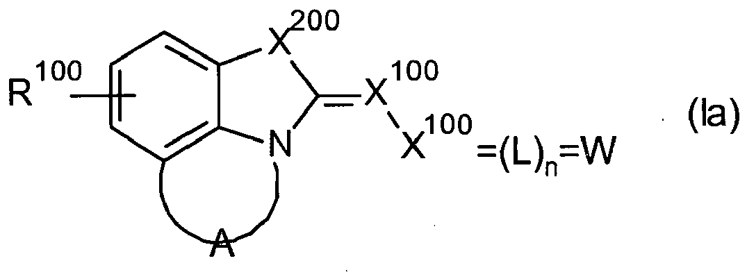 A eine Brücke bestehend aus zwei oder drei sp3-hybridisierten Kohlenstoffatomen, in welcher jedes Kohlenstoffatom zusätzlich noch mit je einem Substituenten R101 substituiert oder welche benzanelliert sein kann,W C(CN)2L ein zweiwertiger, gegebenenfalls ein- oder mehrfach anellierter Carbo- oder Heterocyclus,n 1,X100 CHX200 C(R111)2,R100 H, Alkyl, C1-C6-Alkylen-COO-Alkyl, C1-C6-Alkylen-O-CO-Alkyl, C1-C6- Alkylen-O-CO-O-Alkyl, Cylcloalkyl, Arylalkyl, Aryl, OR110, SR110, Hetaryl, Halogen, NO2 oder CN,R101 Alkyl, C1-C6-Alkylen-COO-Alkyl, C1-C6-Alkylen-O-CO-Alkyl, C1-C6- Alkylen-O-CO-O-Alkyl, Cylcloalkyl, Arylalkyl, Aryl oder Hetaryl,R110 H, Alkyl, C1-C6-Alkylen-COO-Alkyl, C1-C6-Alkylen-O-CO-Alkyl, C1-C6- Alkylen-O-CO-O-Alkyl, Cylcloalkyl, Arylalkyl oder Aryl,R111 H, Alkyl, C1-C6-Alkylen-COO-Alkyl, C1-C6-Alkylen-O-CO-Alkyl, C1-C6- Alkylen-O-CO-O-Alkyl, Cylcloalkyl, Arylalkyl, Aryl oder Hetaryl,wobei die Kohlenstoffketten der Alkyl- und Cylcloalkyl-Reste durch ein oder zwei nicht benachbarte Sauerstoffatome unterbrochen sein können, und die zuvor genannten Variablen, sofern sie mehr als einmal auftreten, gleich oder voneinander verschieden sein könnenund
K2) eine oder mehrere Verbindungen, welche gegenüber Komponente K1) entsprechend als Elektronenakzeptor bzw. Elektronendonor wirken,
zur Herstellung von photoaktiven Schichten für organische Solarzellen und organische Photodetektoren. - Verwendung nach Anspruch 1, dadurch gekennzeichnet, dass in der Formel la von Anspruch 1 L eine Gruppierung
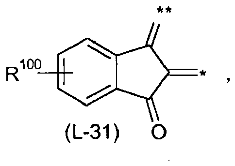
worin * und ** die Anbindung an die Einheit X100 bzw. W bezeichnet, die Kohlenstoffketten der Alkyl- und Cycloalkyl-Reste durch ein oder zwei nicht benachbarte Sauerstoffatome unterbrochen sein können, und
die übrigen Variablen die Bedeutung wie in Anspruch 1 besitzen, und die in Anspruch 1 genannten Variablen, sofern sie mehr als einmal auftreten, gleich oder voneinander verschieden sein können. - Verwendung nach Anspruch 1 oder 2, dadurch gekennzeichnet, dass es sich bei Komponente K2 um eine oder mehrere Verbindungen ausgewählt aus der Gruppea) Fullerene und Fullerenderivate,b) polycyclische aromatische Kohlenwasserstoffe und deren Derivate, insbesondere Naphthalin und dessen Derivate, Rylene, insbesondere Perylen, Terrylen und Quaterrylen, und deren Derivate, Azene, insbesondere Anthrazen, Tetrazen, insbesondere Rubren, Pentazen und deren Derivate, Pyren und dessen Derivate, Coronen und Hexabenzocoronen und deren Derivate,c) Chinone, Chinondimethane und Chinondiimine und deren Derivate,d) Phthalocyanine und Subphthalocyanine und deren Derivate,e) Porphyrine, Tetraazaporphyrine und Tetrabenzoporphyrine und deren Derivate,f) Thiophene, oligo-Thiophene, kondensierte/anellierte Thiophene, wie Thienothiophen und Bithienothiophen, und deren Derivate,g) Thiadiazole und deren Derivate,h) Carbazole und Triarylamine und deren Derivate,i) Indanthrone, Violanthrone und Flavanthone und deren Derivate,j) Fulvalene, Tetrathiafulvalene und Tetraselenafulvalene und deren Derivate undk) Diketopyrrolopyrrole und deren Derivate
handelt. - Verwendung nach Anspruch 1 oder 2, dadurch gekennzeichnet, dass es sich bei Komponente K2 um ein oder mehrere Fullerene und/oder Fulleren-Derivate handelt.
- Verwendung nach einem Anspruch 1 oder 2, dadurch gekennzeichnet, dass es sich bei Komponente K2 um ein oder mehrere Fullerene handelt.
- Verwendung nach Anspruch 1 oder 2, dadurch gekennzeichnet, dass es sich bei Komponente K2 um ein C60-Fulleren handelt.
- Verwendung nach einem oder mehreren der Ansprüche 1 bis 6, dadurch gekennzeichnet, dass die Komponente K1 in einem Anteil von 10 bis 90 Massen-%, insbesondere 20 bis 80 Massen-%, und die Komponente K2 in einem Anteil von 90 bis 10 Massen-%, insbesondere 80 bis 20 Massen-%, vorliegt, wobei sich die Anteile der Komponenten K1 und K2, jeweils bezogen auf die Gesamtmasse der Komponenten K1 und K2, zu 100 Massen-% ergänzen.
- Verfahren zur Herstellung von photoaktiven Schichten, dadurch gekennzeichnet, dass eine oder mehrere Verbindungen der allgemeinen Formel la der Komponente K1 gemäß Anspruch 1 oder 2 und eine oder mehrere Verbindungen der Komponente K2 gemäß Anspruch 3, 4, 5 oder 6 gleichzeitig, nacheinander oder in alternierender Abfolge durch Vakuumsublimation auf einem Substrat abgeschieden werden.
- Verfahren nach Anspruch 8, dadurch gekennzeichnet, dass die Komponenten K1 und K2 nach ihrer Abscheidung in einem Verhältnis gemäß Anspruch 7 auf dem Substrat vorliegen.
- Organische Solarzellen und organische Photodetektoren, enthaltend photoaktive Schichten, welche unter Verwendung von Mischungen gemäß einem oder mehreren der Ansprüche 1 bis 6 hergestellt worden sind oder welche gemäß einem Verfahren nach Anspruch 8 oder 9 erhältlich sind.
- Mischungen, enthaltend als Komponenten eine oder mehrere Verbindungen der allgemeinen Formel la der Komponente K1 gemäß Anspruch 1 oder 2 und ein oder mehrere Verbindungen der Komponente K2 gemäß Anspruch 3, 4, 5 oder 6.
- Mischungen nach Anspruch 11, dadurch gekennzeichnet, dass die Komponente K1 in einem Anteil von 10 bis 90 Massen-%, insbesondere 20 bis 80 Massen-%, und die Komponente K2 in einem Anteil von 90 bis 10 Massen-%, insbesondere 80 bis 20 Massen-%, vorliegt, wobei sich die Anteile der Komponenten K1 und K2, jeweils bezogen auf die Gesamtmasse der Komponenten K1 und K2, zu 100 Massen-% ergänzen.
Priority Applications (1)
| Application Number | Priority Date | Filing Date | Title |
|---|---|---|---|
| EP10768912.7A EP2489084B1 (de) | 2009-10-13 | 2010-10-11 | Mischungen zur herstellung von photoaktiven schichten für organische solarzellen und organische photodetektoren |
Applications Claiming Priority (3)
| Application Number | Priority Date | Filing Date | Title |
|---|---|---|---|
| EP09172939 | 2009-10-13 | ||
| PCT/EP2010/065152 WO2011045253A1 (de) | 2009-10-13 | 2010-10-11 | Mischungen zur herstellung von photoaktiven schichten für organische solarzellen und organische photodetektoren |
| EP10768912.7A EP2489084B1 (de) | 2009-10-13 | 2010-10-11 | Mischungen zur herstellung von photoaktiven schichten für organische solarzellen und organische photodetektoren |
Publications (2)
| Publication Number | Publication Date |
|---|---|
| EP2489084A1 EP2489084A1 (de) | 2012-08-22 |
| EP2489084B1 true EP2489084B1 (de) | 2015-12-23 |
Family
ID=43543747
Family Applications (1)
| Application Number | Title | Priority Date | Filing Date |
|---|---|---|---|
| EP10768912.7A Not-in-force EP2489084B1 (de) | 2009-10-13 | 2010-10-11 | Mischungen zur herstellung von photoaktiven schichten für organische solarzellen und organische photodetektoren |
Country Status (8)
| Country | Link |
|---|---|
| US (1) | US9368729B2 (de) |
| EP (1) | EP2489084B1 (de) |
| JP (1) | JP5714018B2 (de) |
| KR (1) | KR20120093921A (de) |
| CN (1) | CN102549792B (de) |
| AU (1) | AU2010305910B2 (de) |
| WO (1) | WO2011045253A1 (de) |
| ZA (1) | ZA201203354B (de) |
Families Citing this family (11)
| Publication number | Priority date | Publication date | Assignee | Title |
|---|---|---|---|---|
| US9087991B2 (en) | 2011-02-01 | 2015-07-21 | Basf Se | Photovoltaic element |
| KR20140052016A (ko) | 2011-08-12 | 2014-05-02 | 바스프 에스이 | 카르바졸로카르바졸-비스(디카르복스이미드) 및 반도체로서의 그의 용도 |
| US9508944B2 (en) | 2012-04-11 | 2016-11-29 | The Boeing Company | Composite organic-inorganic energy harvesting devices and methods |
| AU2013285053A1 (en) * | 2012-07-04 | 2015-01-15 | Basf Se | Organic dyes comprising hydrazone moiety and use in dye- sensitized solar cells thereof |
| EP2936584A2 (de) * | 2012-12-18 | 2015-10-28 | Merck Patent GmbH | Emitter mit kondensiertem ringsystem |
| CN103078059B (zh) * | 2013-01-29 | 2016-01-06 | 大连交通大学 | 一种用于探测光强度的多层膜及其制备方法 |
| ES2791753T3 (es) * | 2013-10-25 | 2020-11-05 | Stephen R Forrest | Dispositivos fotosensibles orgánicos con filtros portadores de carga de bloqueo de excitones |
| US9139908B2 (en) | 2013-12-12 | 2015-09-22 | The Boeing Company | Gradient thin films |
| CN109134494B (zh) * | 2018-08-31 | 2020-06-05 | 华南协同创新研究院 | 一类含极性取代基团蒽衍生物的电致发光材料及其制备方法与应用 |
| EP4053926A4 (de) * | 2019-10-31 | 2023-03-22 | Sony Group Corporation | Element zur fotoelektrischen umwandlung und bildgebungselement |
| CN113130766B (zh) * | 2021-04-13 | 2022-12-30 | 苏州大学 | 一种有机/聚合物太阳能电池及其活性层 |
Family Cites Families (23)
| Publication number | Priority date | Publication date | Assignee | Title |
|---|---|---|---|---|
| BE440738A (de) * | 1940-03-05 | |||
| US2398999A (en) * | 1942-09-01 | 1946-04-23 | Eastman Kodak Co | Polymethine dyes |
| FR1520818A (fr) | 1966-03-11 | 1968-04-12 | Eastman Kodak Co | Nouveaux colorants du type cyanine et leurs applications en photographie |
| US4743582A (en) * | 1986-10-06 | 1988-05-10 | Eastman Kodak Company | N-alkyl-or n-aryl-aminopyrazolone merocyanine dye-donor element used in thermal dye transfer |
| DE3716656A1 (de) | 1987-05-19 | 1988-12-01 | Basf Ag | Thienonverbindungen |
| DE3929698A1 (de) | 1989-09-07 | 1991-03-14 | Basf Ag | Triazolopyridinfarbstoffe sowie ein verfahren zum thermischen transfer von methinfarbstoffen |
| DE4112654A1 (de) | 1991-04-18 | 1992-10-22 | Basf Ag | Verfahren zur uebertragung von methinfarbstoffen |
| US5703238A (en) | 1994-02-02 | 1997-12-30 | Basf Aktiengesellschaft | Preparation of pyridine dyes |
| DE19502702A1 (de) | 1995-01-28 | 1996-08-01 | Basf Ag | Thiazolmethinfarbstoffe |
| US6086637A (en) * | 1996-11-23 | 2000-07-11 | Basf Aktiengesellschaft | Trifluormethylpyridone based indolenine methine dyes |
| US6337102B1 (en) | 1997-11-17 | 2002-01-08 | The Trustees Of Princeton University | Low pressure vapor phase deposition of organic thin films |
| JP2001523889A (ja) | 1997-11-17 | 2001-11-27 | シメトリックス・コーポレーション | 薄膜のミスト状付着を行うための方法及び装置 |
| DE60140752D1 (de) * | 2000-07-27 | 2010-01-21 | Nippon Kayaku Kk | Farbstoffsensibilisierter photoelektrischer wandler |
| DE10207859A1 (de) | 2002-02-20 | 2003-09-04 | Univ Dresden Tech | Dotiertes organisches Halbleitermaterial sowie Verfahren zu dessen Herstellung |
| AU2004221377B2 (en) | 2003-03-19 | 2009-07-16 | Heliatek Gmbh | Photoactive component comprising organic layers |
| JP4934770B2 (ja) * | 2003-04-15 | 2012-05-16 | 国立大学法人金沢大学 | 有機太陽電池 |
| DE10347856B8 (de) | 2003-10-10 | 2006-10-19 | Colorado State University Research Foundation, Fort Collins | Halbleiterdotierung |
| US7592539B2 (en) | 2003-11-07 | 2009-09-22 | The Trustees Of Princeton University | Solid state photosensitive devices which employ isolated photosynthetic complexes |
| US20050224905A1 (en) | 2004-04-13 | 2005-10-13 | Forrest Stephen R | High efficiency organic photovoltaic cells employing hybridized mixed-planar heterojunctions |
| DE102005010978A1 (de) | 2005-03-04 | 2006-09-07 | Technische Universität Dresden | Photoaktives Bauelement mit organischen Schichten |
| WO2007071450A1 (en) | 2005-12-23 | 2007-06-28 | Novaled Ag | Electronic device with a layer structure of organic layers |
| US20100140559A1 (en) | 2007-07-10 | 2010-06-10 | Basf Se | Mixtures for producing photoactive layers for organic solar cells and organic photodetectors |
| CN102203972A (zh) | 2008-10-31 | 2011-09-28 | 巴斯夫欧洲公司 | 用于制备有机太阳能电池和有机光电探测器用光活化层的部花青 |
-
2010
- 2010-10-11 CN CN201080046165.2A patent/CN102549792B/zh not_active Expired - Fee Related
- 2010-10-11 KR KR1020127011531A patent/KR20120093921A/ko not_active Withdrawn
- 2010-10-11 JP JP2012533591A patent/JP5714018B2/ja not_active Expired - Fee Related
- 2010-10-11 US US13/501,018 patent/US9368729B2/en not_active Expired - Fee Related
- 2010-10-11 AU AU2010305910A patent/AU2010305910B2/en not_active Ceased
- 2010-10-11 WO PCT/EP2010/065152 patent/WO2011045253A1/de not_active Ceased
- 2010-10-11 EP EP10768912.7A patent/EP2489084B1/de not_active Not-in-force
-
2012
- 2012-05-09 ZA ZA2012/03354A patent/ZA201203354B/en unknown
Also Published As
| Publication number | Publication date |
|---|---|
| US9368729B2 (en) | 2016-06-14 |
| CN102549792B (zh) | 2015-11-25 |
| US20120267579A1 (en) | 2012-10-25 |
| AU2010305910A8 (en) | 2012-07-19 |
| AU2010305910A1 (en) | 2012-04-12 |
| ZA201203354B (en) | 2013-07-31 |
| AU2010305910B2 (en) | 2015-03-12 |
| KR20120093921A (ko) | 2012-08-23 |
| JP2013507780A (ja) | 2013-03-04 |
| JP5714018B2 (ja) | 2015-05-07 |
| CN102549792A (zh) | 2012-07-04 |
| WO2011045253A1 (de) | 2011-04-21 |
| EP2489084A1 (de) | 2012-08-22 |
Similar Documents
| Publication | Publication Date | Title |
|---|---|---|
| EP2347460A1 (de) | Merocyanine zur herstellung von photoaktiven schichten für organische solarzellen und organische photodetektoren | |
| AU2010305910B2 (en) | Mixtures for producing photoactive layers for organic solar cells and organic photodetectors | |
| EP3050134B9 (de) | Photoaktives, organisches material für optoelektronische bauelemente | |
| EP2181172B1 (de) | Halogenhaltige perylentetracarbonsäurederivate und deren verwendung | |
| EP2168181B1 (de) | Mischungen zur herstellung von photoaktiven schichten für organische solarzellen und organische photodetektoren | |
| JP6542217B2 (ja) | ヘテロ接合型有機太陽電池用の新規吸収体 | |
| EP2433317B1 (de) | Halbleitendes bauelement | |
| EP2329539A1 (de) | Verwendung von dibenzotetraphenylperiflanthen in organischen solarzellen | |
| EP2976794B1 (de) | Photoaktives, organisches material für optoelektronische bauelemente | |
| EP3044818B1 (de) | Vorrichtung der organischen elektronik mit aktiver schicht | |
| EP4271677A1 (de) | Verbindung für ein optoelektronisches bauelement und optoelektronisches bauelement enthaltend die verbindung | |
| DE102009021882B4 (de) | Organisches halbleitendes Bauelement | |
| DE102022125417A1 (de) | Chemische Verbindung, optoelektronisches Bauelement mit mindestens einer solchen chemischen Verbindung, und Verwendung mindestens einer solchen chemischen Verbindung in einem optoelektronischen Bauelement | |
| DE102020135172A1 (de) | Verbindung und deren Verwendung in organischen elektronischen Bauelementen |
Legal Events
| Date | Code | Title | Description |
|---|---|---|---|
| PUAI | Public reference made under article 153(3) epc to a published international application that has entered the european phase |
Free format text: ORIGINAL CODE: 0009012 |
|
| 17P | Request for examination filed |
Effective date: 20120514 |
|
| AK | Designated contracting states |
Kind code of ref document: A1 Designated state(s): AL AT BE BG CH CY CZ DE DK EE ES FI FR GB GR HR HU IE IS IT LI LT LU LV MC MK MT NL NO PL PT RO RS SE SI SK SM TR |
|
| DAX | Request for extension of the european patent (deleted) | ||
| 17Q | First examination report despatched |
Effective date: 20140729 |
|
| GRAP | Despatch of communication of intention to grant a patent |
Free format text: ORIGINAL CODE: EPIDOSNIGR1 |
|
| INTG | Intention to grant announced |
Effective date: 20141212 |
|
| GRAP | Despatch of communication of intention to grant a patent |
Free format text: ORIGINAL CODE: EPIDOSNIGR1 |
|
| INTG | Intention to grant announced |
Effective date: 20150521 |
|
| GRAS | Grant fee paid |
Free format text: ORIGINAL CODE: EPIDOSNIGR3 |
|
| GRAA | (expected) grant |
Free format text: ORIGINAL CODE: 0009210 |
|
| AK | Designated contracting states |
Kind code of ref document: B1 Designated state(s): AL AT BE BG CH CY CZ DE DK EE ES FI FR GB GR HR HU IE IS IT LI LT LU LV MC MK MT NL NO PL PT RO RS SE SI SK SM TR |
|
| REG | Reference to a national code |
Ref country code: GB Ref legal event code: FG4D Free format text: NOT ENGLISH |
|
| REG | Reference to a national code |
Ref country code: CH Ref legal event code: EP |
|
| REG | Reference to a national code |
Ref country code: IE Ref legal event code: FG4D Free format text: LANGUAGE OF EP DOCUMENT: GERMAN |
|
| REG | Reference to a national code |
Ref country code: AT Ref legal event code: REF Ref document number: 766884 Country of ref document: AT Kind code of ref document: T Effective date: 20160115 |
|
| REG | Reference to a national code |
Ref country code: DE Ref legal event code: R096 Ref document number: 502010010833 Country of ref document: DE |
|
| REG | Reference to a national code |
Ref country code: LT Ref legal event code: MG4D |
|
| REG | Reference to a national code |
Ref country code: NL Ref legal event code: MP Effective date: 20151223 |
|
| PG25 | Lapsed in a contracting state [announced via postgrant information from national office to epo] |
Ref country code: HR Free format text: LAPSE BECAUSE OF FAILURE TO SUBMIT A TRANSLATION OF THE DESCRIPTION OR TO PAY THE FEE WITHIN THE PRESCRIBED TIME-LIMIT Effective date: 20151223 Ref country code: NO Free format text: LAPSE BECAUSE OF FAILURE TO SUBMIT A TRANSLATION OF THE DESCRIPTION OR TO PAY THE FEE WITHIN THE PRESCRIBED TIME-LIMIT Effective date: 20160323 Ref country code: LT Free format text: LAPSE BECAUSE OF FAILURE TO SUBMIT A TRANSLATION OF THE DESCRIPTION OR TO PAY THE FEE WITHIN THE PRESCRIBED TIME-LIMIT Effective date: 20151223 |
|
| PG25 | Lapsed in a contracting state [announced via postgrant information from national office to epo] |
Ref country code: SE Free format text: LAPSE BECAUSE OF FAILURE TO SUBMIT A TRANSLATION OF THE DESCRIPTION OR TO PAY THE FEE WITHIN THE PRESCRIBED TIME-LIMIT Effective date: 20151223 Ref country code: FI Free format text: LAPSE BECAUSE OF FAILURE TO SUBMIT A TRANSLATION OF THE DESCRIPTION OR TO PAY THE FEE WITHIN THE PRESCRIBED TIME-LIMIT Effective date: 20151223 Ref country code: GR Free format text: LAPSE BECAUSE OF FAILURE TO SUBMIT A TRANSLATION OF THE DESCRIPTION OR TO PAY THE FEE WITHIN THE PRESCRIBED TIME-LIMIT Effective date: 20160324 Ref country code: LV Free format text: LAPSE BECAUSE OF FAILURE TO SUBMIT A TRANSLATION OF THE DESCRIPTION OR TO PAY THE FEE WITHIN THE PRESCRIBED TIME-LIMIT Effective date: 20151223 Ref country code: NL Free format text: LAPSE BECAUSE OF FAILURE TO SUBMIT A TRANSLATION OF THE DESCRIPTION OR TO PAY THE FEE WITHIN THE PRESCRIBED TIME-LIMIT Effective date: 20151223 Ref country code: RS Free format text: LAPSE BECAUSE OF FAILURE TO SUBMIT A TRANSLATION OF THE DESCRIPTION OR TO PAY THE FEE WITHIN THE PRESCRIBED TIME-LIMIT Effective date: 20151223 |
|
| PG25 | Lapsed in a contracting state [announced via postgrant information from national office to epo] |
Ref country code: ES Free format text: LAPSE BECAUSE OF FAILURE TO SUBMIT A TRANSLATION OF THE DESCRIPTION OR TO PAY THE FEE WITHIN THE PRESCRIBED TIME-LIMIT Effective date: 20151223 Ref country code: CZ Free format text: LAPSE BECAUSE OF FAILURE TO SUBMIT A TRANSLATION OF THE DESCRIPTION OR TO PAY THE FEE WITHIN THE PRESCRIBED TIME-LIMIT Effective date: 20151223 |
|
| PG25 | Lapsed in a contracting state [announced via postgrant information from national office to epo] |
Ref country code: SM Free format text: LAPSE BECAUSE OF FAILURE TO SUBMIT A TRANSLATION OF THE DESCRIPTION OR TO PAY THE FEE WITHIN THE PRESCRIBED TIME-LIMIT Effective date: 20151223 Ref country code: PL Free format text: LAPSE BECAUSE OF FAILURE TO SUBMIT A TRANSLATION OF THE DESCRIPTION OR TO PAY THE FEE WITHIN THE PRESCRIBED TIME-LIMIT Effective date: 20151223 Ref country code: IS Free format text: LAPSE BECAUSE OF FAILURE TO SUBMIT A TRANSLATION OF THE DESCRIPTION OR TO PAY THE FEE WITHIN THE PRESCRIBED TIME-LIMIT Effective date: 20160423 Ref country code: SK Free format text: LAPSE BECAUSE OF FAILURE TO SUBMIT A TRANSLATION OF THE DESCRIPTION OR TO PAY THE FEE WITHIN THE PRESCRIBED TIME-LIMIT Effective date: 20151223 Ref country code: RO Free format text: LAPSE BECAUSE OF FAILURE TO SUBMIT A TRANSLATION OF THE DESCRIPTION OR TO PAY THE FEE WITHIN THE PRESCRIBED TIME-LIMIT Effective date: 20151223 Ref country code: PT Free format text: LAPSE BECAUSE OF FAILURE TO SUBMIT A TRANSLATION OF THE DESCRIPTION OR TO PAY THE FEE WITHIN THE PRESCRIBED TIME-LIMIT Effective date: 20160426 Ref country code: EE Free format text: LAPSE BECAUSE OF FAILURE TO SUBMIT A TRANSLATION OF THE DESCRIPTION OR TO PAY THE FEE WITHIN THE PRESCRIBED TIME-LIMIT Effective date: 20151223 |
|
| REG | Reference to a national code |
Ref country code: DE Ref legal event code: R097 Ref document number: 502010010833 Country of ref document: DE |
|
| PLBE | No opposition filed within time limit |
Free format text: ORIGINAL CODE: 0009261 |
|
| STAA | Information on the status of an ep patent application or granted ep patent |
Free format text: STATUS: NO OPPOSITION FILED WITHIN TIME LIMIT |
|
| PG25 | Lapsed in a contracting state [announced via postgrant information from national office to epo] |
Ref country code: DK Free format text: LAPSE BECAUSE OF FAILURE TO SUBMIT A TRANSLATION OF THE DESCRIPTION OR TO PAY THE FEE WITHIN THE PRESCRIBED TIME-LIMIT Effective date: 20151223 |
|
| 26N | No opposition filed |
Effective date: 20160926 |
|
| PG25 | Lapsed in a contracting state [announced via postgrant information from national office to epo] |
Ref country code: BE Free format text: LAPSE BECAUSE OF NON-PAYMENT OF DUE FEES Effective date: 20161031 Ref country code: SI Free format text: LAPSE BECAUSE OF FAILURE TO SUBMIT A TRANSLATION OF THE DESCRIPTION OR TO PAY THE FEE WITHIN THE PRESCRIBED TIME-LIMIT Effective date: 20151223 |
|
| REG | Reference to a national code |
Ref country code: DE Ref legal event code: R119 Ref document number: 502010010833 Country of ref document: DE |
|
| REG | Reference to a national code |
Ref country code: CH Ref legal event code: PL |
|
| GBPC | Gb: european patent ceased through non-payment of renewal fee |
Effective date: 20161011 |
|
| REG | Reference to a national code |
Ref country code: IE Ref legal event code: MM4A |
|
| REG | Reference to a national code |
Ref country code: FR Ref legal event code: ST Effective date: 20170630 |
|
| PG25 | Lapsed in a contracting state [announced via postgrant information from national office to epo] |
Ref country code: FR Free format text: LAPSE BECAUSE OF NON-PAYMENT OF DUE FEES Effective date: 20161102 Ref country code: DE Free format text: LAPSE BECAUSE OF NON-PAYMENT OF DUE FEES Effective date: 20170503 Ref country code: CH Free format text: LAPSE BECAUSE OF NON-PAYMENT OF DUE FEES Effective date: 20161031 Ref country code: GB Free format text: LAPSE BECAUSE OF NON-PAYMENT OF DUE FEES Effective date: 20161011 Ref country code: LI Free format text: LAPSE BECAUSE OF NON-PAYMENT OF DUE FEES Effective date: 20161031 |
|
| PG25 | Lapsed in a contracting state [announced via postgrant information from national office to epo] |
Ref country code: LU Free format text: LAPSE BECAUSE OF NON-PAYMENT OF DUE FEES Effective date: 20161011 |
|
| PG25 | Lapsed in a contracting state [announced via postgrant information from national office to epo] |
Ref country code: IT Free format text: LAPSE BECAUSE OF NON-PAYMENT OF DUE FEES Effective date: 20161011 |
|
| PG25 | Lapsed in a contracting state [announced via postgrant information from national office to epo] |
Ref country code: IE Free format text: LAPSE BECAUSE OF NON-PAYMENT OF DUE FEES Effective date: 20161011 |
|
| REG | Reference to a national code |
Ref country code: BE Ref legal event code: MM Effective date: 20161031 |
|
| REG | Reference to a national code |
Ref country code: AT Ref legal event code: MM01 Ref document number: 766884 Country of ref document: AT Kind code of ref document: T Effective date: 20161011 |
|
| PG25 | Lapsed in a contracting state [announced via postgrant information from national office to epo] |
Ref country code: AT Free format text: LAPSE BECAUSE OF NON-PAYMENT OF DUE FEES Effective date: 20161011 |
|
| PG25 | Lapsed in a contracting state [announced via postgrant information from national office to epo] |
Ref country code: HU Free format text: LAPSE BECAUSE OF FAILURE TO SUBMIT A TRANSLATION OF THE DESCRIPTION OR TO PAY THE FEE WITHIN THE PRESCRIBED TIME-LIMIT; INVALID AB INITIO Effective date: 20101011 Ref country code: CY Free format text: LAPSE BECAUSE OF FAILURE TO SUBMIT A TRANSLATION OF THE DESCRIPTION OR TO PAY THE FEE WITHIN THE PRESCRIBED TIME-LIMIT Effective date: 20151223 |
|
| PG25 | Lapsed in a contracting state [announced via postgrant information from national office to epo] |
Ref country code: MT Free format text: LAPSE BECAUSE OF FAILURE TO SUBMIT A TRANSLATION OF THE DESCRIPTION OR TO PAY THE FEE WITHIN THE PRESCRIBED TIME-LIMIT Effective date: 20151223 Ref country code: TR Free format text: LAPSE BECAUSE OF FAILURE TO SUBMIT A TRANSLATION OF THE DESCRIPTION OR TO PAY THE FEE WITHIN THE PRESCRIBED TIME-LIMIT Effective date: 20151223 Ref country code: MC Free format text: LAPSE BECAUSE OF FAILURE TO SUBMIT A TRANSLATION OF THE DESCRIPTION OR TO PAY THE FEE WITHIN THE PRESCRIBED TIME-LIMIT Effective date: 20151223 Ref country code: MK Free format text: LAPSE BECAUSE OF FAILURE TO SUBMIT A TRANSLATION OF THE DESCRIPTION OR TO PAY THE FEE WITHIN THE PRESCRIBED TIME-LIMIT Effective date: 20151223 |
|
| PG25 | Lapsed in a contracting state [announced via postgrant information from national office to epo] |
Ref country code: BG Free format text: LAPSE BECAUSE OF FAILURE TO SUBMIT A TRANSLATION OF THE DESCRIPTION OR TO PAY THE FEE WITHIN THE PRESCRIBED TIME-LIMIT Effective date: 20151223 |
|
| PG25 | Lapsed in a contracting state [announced via postgrant information from national office to epo] |
Ref country code: AL Free format text: LAPSE BECAUSE OF FAILURE TO SUBMIT A TRANSLATION OF THE DESCRIPTION OR TO PAY THE FEE WITHIN THE PRESCRIBED TIME-LIMIT Effective date: 20151223 |