EP2485668B1 - Entladedynamische intervertebrale vorrichtung - Google Patents
Entladedynamische intervertebrale vorrichtung Download PDFInfo
- Publication number
- EP2485668B1 EP2485668B1 EP10779060.2A EP10779060A EP2485668B1 EP 2485668 B1 EP2485668 B1 EP 2485668B1 EP 10779060 A EP10779060 A EP 10779060A EP 2485668 B1 EP2485668 B1 EP 2485668B1
- Authority
- EP
- European Patent Office
- Prior art keywords
- bars
- guideline
- guide
- closed position
- situated
- Prior art date
- Legal status (The legal status is an assumption and is not a legal conclusion. Google has not performed a legal analysis and makes no representation as to the accuracy of the status listed.)
- Not-in-force
Links
Images


Classifications
-
- A—HUMAN NECESSITIES
- A61—MEDICAL OR VETERINARY SCIENCE; HYGIENE
- A61B—DIAGNOSIS; SURGERY; IDENTIFICATION
- A61B17/00—Surgical instruments, devices or methods
- A61B17/56—Surgical instruments or methods for treatment of bones or joints; Devices specially adapted therefor
- A61B17/58—Surgical instruments or methods for treatment of bones or joints; Devices specially adapted therefor for osteosynthesis, e.g. bone plates, screws or setting implements
- A61B17/68—Internal fixation devices, including fasteners and spinal fixators, even if a part thereof projects from the skin
- A61B17/70—Spinal positioners or stabilisers, e.g. stabilisers comprising fluid filler in an implant
- A61B17/7062—Devices acting on, attached to, or simulating the effect of, vertebral processes, vertebral facets or ribs ; Tools for such devices
- A61B17/7065—Devices with changeable shape, e.g. collapsible or having retractable arms to aid implantation; Tools therefor
-
- A—HUMAN NECESSITIES
- A61—MEDICAL OR VETERINARY SCIENCE; HYGIENE
- A61B—DIAGNOSIS; SURGERY; IDENTIFICATION
- A61B17/00—Surgical instruments, devices or methods
- A61B17/56—Surgical instruments or methods for treatment of bones or joints; Devices specially adapted therefor
- A61B17/58—Surgical instruments or methods for treatment of bones or joints; Devices specially adapted therefor for osteosynthesis, e.g. bone plates, screws or setting implements
- A61B17/68—Internal fixation devices, including fasteners and spinal fixators, even if a part thereof projects from the skin
- A61B17/80—Cortical plates, i.e. bone plates; Instruments for holding or positioning cortical plates, or for compressing bones attached to cortical plates
-
- A—HUMAN NECESSITIES
- A61—MEDICAL OR VETERINARY SCIENCE; HYGIENE
- A61F—FILTERS IMPLANTABLE INTO BLOOD VESSELS; PROSTHESES; DEVICES PROVIDING PATENCY TO, OR PREVENTING COLLAPSING OF, TUBULAR STRUCTURES OF THE BODY, e.g. STENTS; ORTHOPAEDIC, NURSING OR CONTRACEPTIVE DEVICES; FOMENTATION; TREATMENT OR PROTECTION OF EYES OR EARS; BANDAGES, DRESSINGS OR ABSORBENT PADS; FIRST-AID KITS
- A61F2/00—Filters implantable into blood vessels; Prostheses, i.e. artificial substitutes or replacements for parts of the body; Appliances for connecting them with the body; Devices providing patency to, or preventing collapsing of, tubular structures of the body, e.g. stents
- A61F2/02—Prostheses implantable into the body
- A61F2/30—Joints
- A61F2/44—Joints for the spine, e.g. vertebrae, spinal discs
- A61F2/442—Intervertebral or spinal discs, e.g. resilient
- A61F2/4425—Intervertebral or spinal discs, e.g. resilient made of articulated components
-
- A—HUMAN NECESSITIES
- A61—MEDICAL OR VETERINARY SCIENCE; HYGIENE
- A61F—FILTERS IMPLANTABLE INTO BLOOD VESSELS; PROSTHESES; DEVICES PROVIDING PATENCY TO, OR PREVENTING COLLAPSING OF, TUBULAR STRUCTURES OF THE BODY, e.g. STENTS; ORTHOPAEDIC, NURSING OR CONTRACEPTIVE DEVICES; FOMENTATION; TREATMENT OR PROTECTION OF EYES OR EARS; BANDAGES, DRESSINGS OR ABSORBENT PADS; FIRST-AID KITS
- A61F2/00—Filters implantable into blood vessels; Prostheses, i.e. artificial substitutes or replacements for parts of the body; Appliances for connecting them with the body; Devices providing patency to, or preventing collapsing of, tubular structures of the body, e.g. stents
- A61F2/02—Prostheses implantable into the body
- A61F2/30—Joints
- A61F2/46—Special tools for implanting artificial joints
- A61F2/4603—Special tools for implanting artificial joints for insertion or extraction of endoprosthetic joints or of accessories thereof
- A61F2/4611—Special tools for implanting artificial joints for insertion or extraction of endoprosthetic joints or of accessories thereof of spinal prostheses
-
- A—HUMAN NECESSITIES
- A61—MEDICAL OR VETERINARY SCIENCE; HYGIENE
- A61F—FILTERS IMPLANTABLE INTO BLOOD VESSELS; PROSTHESES; DEVICES PROVIDING PATENCY TO, OR PREVENTING COLLAPSING OF, TUBULAR STRUCTURES OF THE BODY, e.g. STENTS; ORTHOPAEDIC, NURSING OR CONTRACEPTIVE DEVICES; FOMENTATION; TREATMENT OR PROTECTION OF EYES OR EARS; BANDAGES, DRESSINGS OR ABSORBENT PADS; FIRST-AID KITS
- A61F2/00—Filters implantable into blood vessels; Prostheses, i.e. artificial substitutes or replacements for parts of the body; Appliances for connecting them with the body; Devices providing patency to, or preventing collapsing of, tubular structures of the body, e.g. stents
- A61F2/02—Prostheses implantable into the body
- A61F2/30—Joints
- A61F2002/30001—Additional features of subject-matter classified in A61F2/28, A61F2/30 and subgroups thereof
- A61F2002/30316—The prosthesis having different structural features at different locations within the same prosthesis; Connections between prosthetic parts; Special structural features of bone or joint prostheses not otherwise provided for
- A61F2002/30329—Connections or couplings between prosthetic parts, e.g. between modular parts; Connecting elements
- A61F2002/30331—Connections or couplings between prosthetic parts, e.g. between modular parts; Connecting elements made by longitudinally pushing a protrusion into a complementarily-shaped recess, e.g. held by friction fit
- A61F2002/30362—Connections or couplings between prosthetic parts, e.g. between modular parts; Connecting elements made by longitudinally pushing a protrusion into a complementarily-shaped recess, e.g. held by friction fit with possibility of relative movement between the protrusion and the recess
- A61F2002/30364—Rotation about the common longitudinal axis
- A61F2002/30367—Rotation about the common longitudinal axis with additional means for preventing said rotation
Definitions
- the scope of the invention is an unloading-dynamic intervertebral device, used in spinal surgery.
- the device is used for an even, steady and adjustable decompression of the intervertebral interspinous space and for maintaining the distance between at least two vertebrae, and also for the treatment of pathologic lateral deformations of the spine by supporting the device on bony elements of the posterior spinal column, especially on spinous processes and neural arches.
- Stabilizers used for interspinous spinal stabilization using a surgical posterior approach are usually known in the form of one or several cooperating carrying elements situated in the interspinous space, ended with profiled sockets for spinous processes. Such stabilizers situated in the axis of the spine serve mainly for one-level stabilization of the adjoining vertebrae.
- Solutions are also known in the form of lamellar or rod bearing elements with an adjustable length, installed in the interspinous space and comprising hook elements resting against on spinous processes.
- Such stabilizers can be used for supporting the spine on one and several levels.
- US 2008/0208344 A1 and US 2009/0149886 A1 each describe an intervertebral implant device with an implant body.
- the implant body comprises a first portion and a second portion that is adjustably interconnected with the first portion.
- the first portion comprises a pin located in an opening of the second portion.
- the first portion comprises an arm with a locking projecting cooperating with a lock recess in the second portion.
- US 2007/0100340A1 describes an intervertebral device which comprises two spacers. A slot and a screw cooperate to allow a sliding movement between the two spacers and, as a consequence, a variation in axial length of the implant in response to the movements of a patient.
- US 2007/0270827 A1 describes an adjustable interspinous process brace which includes a superior component with a superior spinous process bracket and an inferior component with an inferior spinous process bracket.
- the inferior component can be movably engaged with the superior component from a retracted position to an extended position such that a distance between the superior spinous process bracket and the inferior spinous process bracket can be increased.
- An interspinous implant situated non-axially in relation to the spine is known from the patent application WO2007/127550 , comprising superior and inferior bearing elements cooperating in a sliding way along the axis corresponding to the axis of the spine. Lateral separated bearing elements are ended with brackets for fastening onto superior and inferior spinal interspinous processes, respectively. In a folded position, the device is of the height allowing its installation between spinal processes and the interspinous space is increased by distraction of both elements:
- An axial interspinous implant in the form of a frame embracing exteriorly vertebral processes is disclosed in the patent application WO 2007/127694 .
- the frame is in the form of a ring or its parts provided with holes situated on both sides of the axis, through which elastic bands are drawn out.
- the bands constitute bearing elements pulling off superior and inferior processes respectively to the superior and inferior part of the frame.
- the place of connection of the implant with the bone can be secured by sharp projections constituting an integral part of internal surfaces of the frame.
- an interspinous implant which contains a bearing supporting part with profiled sockets located axially between adjoining spinous processes and two hook elements connected by an elastic band which passes through the support.
- the hooks fasten the processes from the superior side preventing excessive flexion of the spinal motion segment.
- the patent application WO 01/91658 discloses a device and the method of its application for distraction of adjacent spinous processes. The device has got a bracket with a guide fastened by a connector to a laterally separated rod element ended with hooks, which embrace spinous processes. The construction of the device allows rotational movement between the bracket and the hook.
- a multi-segment stabilizer for controlling the intervertebral space is known from the patent application US 4611582 .
- the body comprises a longitudinal, laterally separated bearing body and two laminar clamps.
- the clamps are in the form of two alternating hooks, both of them are adapted for a rigid, bilateral embrace of a part of one vertebra.
- the body is dual, it consists of movable cooperating parts connected with each other by threaded elements fastening and adjusting body's length.
- the patent application US 5439463 refers to a spinal device which consists of two clamp elements ended with hook parts: a fixed one with a rod setting the distance, and an adjustable one.
- the surface of the rod and the corresponding surface of the adjustable clamp cooperate in a sliding way through toothed surfaces and their cooperation is secured by a distance fastening element provided with a clamping ring and threaded screw.
- a device for implantation and distraction of spinal spinous processes is known from the patent application WO 2008/085445 . It consists of a longitudinal body and two sliding elements. Each of them is composed of the main part cooperating with the body and hook arms for support on the bone. In an embodiment of the device, the arms are provided with a rough surface increasing friction in the area of contact of the implant and a spinous process.
- the unloading-dynamic intervertebral device is free of the above drawbacks. It consists of two bars cooperating with each other, where each of them is ended from one side with a shaped bearing for bony elements of the spine. According to the invention, one of the bars is provided with a guideline, whereas the other with a guide. Moreover, the first bar is provided with at least one tang, situated in the corresponding shaped gap of the other bar, assuring rotatable and rotatable-sliding cooperation of the bars crossing in the open position of the device. The device is equipped with a mechanism blocking rotational movement of the bars in the closed position.
- the guideline is provided with at least one tang situated in the guide's gap or at least one shaped gap made in the guideline cooperates with the ends of the tang fixed in the guide.
- the tang connected with the guide is situated in the guideline.
- a notch located in the end of the guide and a projection made in the guideline which cooperates with the guide constitute the mechanism blocking rotational movement of the bars and their mutual location in the closed position of the device.
- the mechanism blocking rotational movement of the bars in the closed position of the device is formed by a projection made in the end of the guide cooperating with the notch made in the guideline.
- the guide or the guideline are provided with at least one shaped gap ended with a socket. The tang constituting an element of the mechanism blocking rotational movement of the bars in the closed position of the device is situated in the socket.
- shaped gaps in the guideline or the guide of the device are through. It is also preferable to connect the shaped gap with the input canal, thus enabling introduction of the tang.
- the mechanism blocking rotational movement of the bars in the closed position of the device preferably comprises a plate situated in the shaped gaps of the two-arm guideline.
- a pin setting the mutual position of the guide and the guideline constitute the mechanism blocking movement of the bars in the closed position.
- At least one shaped bearing constitutes a separate element moveably connected to the corresponding bar.
- At least one bearing is provided with at least one incision , thus imparting resilience to the construction.
- the device is provided with a scale showing the value of distraction, which will be obtained in the closed position of the device.
- the bars of the device are provided with at least one means for guiding the band.
- the unloading-dynamic intervertebral device according to the invention is used to support dysfunctions of any spinal segment, including also deformities.
- the device can be used at one or many levels with unilateral or bilateral support on spinous processes and/or simultaneously on bony elements adjoining the spinous processes, such as neural arches.
- the device according to the invention offers the possibility of steady and even intervertebral distraction already during the process of installation between bony elements, which is not possible in other solutions, it decreases the risk of an incorrect selection of implant's dimensions, excludes the use of additional surgical instruments, such as distracters, and decreases the load on tissues included in stabilization. Owing to mutual mobility of interconnected arms, possibilities of their angular alignment and thanks to an adjustable point of rotation, the device assures an adjustable range of distraction with the use of only one device, without the necessity of having the full dimensional series.
- Application of multilevel stabilization allows distribution of loads on a greater surface and a longer spinal segment, and it also improves spinal biomechanics.
- Stabilization of many spinal levels affects unloading dysfunctional vertebrae, which can be additionally supported by employing other ways of stabilization.
- the device and the method of its implantation are characterized by small invasiveness, unilateral surgical approach, which allows for retainment of the supraspinous ligament, which is of importance in stabilizing the posterior spinal column. In some cases, justified by the clinical condition, the device can also be used bilaterally. Implantation of the device is easy and quick, thus affecting the duration of surgery and can be realized in variants, depending on restrictions of the operating field following from the level and anatomy of the osteoarticular system being stabilized.
- the plane of closing the device by rotational and rotational-sliding movement can be approximate to the sagittal plane of the spine or can be inclined to it at an angle of 90°, which gives an operating surgeon greater possibilities of installation.
- the construction and dimensions of the device offer possibilities of treating patients from various age groups.
- fig. 1 illustrates one embodiment of the device depicting elements of the blocking mechanism
- fig. 2 shows in the section a fragment of the movable connection of the bars
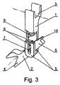
- fig. 3 illustrates one embodiment of the device in axonometric projection in an open position with perpendicular orientation of bearings and a part section depicting the blocking mechanism
- fig. 4 illustrates in axonometric projection one embodiment of the device with the one-arm guideline, blocking mechanism in the form of a pin and clamping band
- fig. 5 presents in axonometric projection an embodiment of the device equipped with a scale and incisions in the bearing.
- the unloading-dynamic intervertebral device is composed of two movable cooperating bars 1,2, whose implantation in the area of spinal dysfunction consists in passing from the open position to closed position making use of the simultaneous displacement of bony elements during distraction.
- Each bar 1, 2 is ended from one side with a shaped bearing 3, 4 for vertebral bony elements, such as: the spinous process or the neural arch.
- one of the bars - bar 1 is ended with a two-arm guideline 5, whereas the other bar - bar 2 with a guide 6.
- Sliding-rotational and rotational cooperation of bars 1, 2 crossing in an open position is realized by: tangs 7 situated on internal surfaces of guideline 5 and blind shaped gaps 8 in guide 6, as shown in fig. 2 .
- a blocking mechanism In a closed position of the device, the reverse movement of bars 1, 2 is blocked by a blocking mechanism.
- This mechanism consists of notch 9 situated on the end of guide 6 and projection 10 made in the guideline 3 cooperating with it.
- notch 9 is made in guideline 3
- projection 10 constitutes a constructional fragment of the end of guide 6.
- Sliding-rotational and rotational cooperation of bars 1, 2 which cross with each other in the open position is realized by the ends of tang 7 fastened in guide 6 which cooperate with two through shaped gaps 8 made in the guideline 5.
- variously oriented bearings 3, 4 allow the device to rest at the same time on the spinous process of one vertebra and the neural arch of the other vertebra.
- Elements of the connection may constitute a three-dimensional joint or a flat one, as shown in fig. 4 .
- a threaded pin 14 passing through the one-arm guideline 5 and guide 6 constitutes the blocking mechanism.
- the device is provided with means 15 which guides band 16, which secures the device, thanks to its fixation to bony elements, against shifting in the patient's body.
- the bearing 4 is provided with two incisions 17 increasing its resilience and giving the device dynamic features.
- the device is equipped with scale 18 of angular arrangement of bars 1, 2 in an open position, which provides information about the range of distraction in the closed position of the device.
- a threaded pin 14 passing through the one-arm guideline 5 and guide 6 constitutes the blocking mechanism.
- the device is provided with means 15 which guides band 16, which secures the device, thanks to its fixation to bony elements, against shifting in the patient's body.
- the bearing 4 is provided with two incisions 17 increasing its resilience and giving the device dynamic features.
- the device is equipped with scale 18 of angular arrangement of bars 1, 2 in an open position, which provides information about the range of distraction in the closed position of the device.
Landscapes
- Health & Medical Sciences (AREA)
- Orthopedic Medicine & Surgery (AREA)
- Neurology (AREA)
- Life Sciences & Earth Sciences (AREA)
- Engineering & Computer Science (AREA)
- Biomedical Technology (AREA)
- Surgery (AREA)
- General Health & Medical Sciences (AREA)
- Veterinary Medicine (AREA)
- Heart & Thoracic Surgery (AREA)
- Public Health (AREA)
- Animal Behavior & Ethology (AREA)
- Molecular Biology (AREA)
- Medical Informatics (AREA)
- Nuclear Medicine, Radiotherapy & Molecular Imaging (AREA)
- Transplantation (AREA)
- Cardiology (AREA)
- Oral & Maxillofacial Surgery (AREA)
- Vascular Medicine (AREA)
- Physical Education & Sports Medicine (AREA)
- Prostheses (AREA)
- Surgical Instruments (AREA)
Claims (14)
- Eine entlastende dynamische intervertebrale Vorrichtung, bestehend aus zwei Riegeln (1, 2), die miteinander kooperieren, wobei- jeder der Riegel (1, 2) auf einer Seite in einer geformten Auflage (3, 4) für knöcherne Elemente der Wirbelsäule endet,- einer der Riegel (1, 2) mit einer Führung (5) und der andere mit einem Führungsteil (6) bereitgestellt wird,- einer der Riegel (1, 2) mit einer Formöffnung(8) versehen ist,- der andere Riegel (1, 2) mit mindestens einem Zapfen (7) bereitgestellt wird, der sich in der entsprechenden Formöffnung (8) des anderen Riegels (2, 1) befindet und eine Rotationsbewegung der Riegel (1, 2) um den Zapfen (7) sicherstellt, wobei sich die Riegel in einer offenen Position der Vorrichtung überkreuzen, unddadurch gekennzeichnet, dass
die Vorrichtung mit einem Mechanismus versehen ist, der die Rotationsbewegung der Riegel (1, 2) in der geschlossenen Position blockiert,
die Formöffnung eine längliche Öffnung (8) darstellt, die ein rotierend-gleitendes Zusammenwirken der Riegel (1, 2) sicherstellt, und ein Einstellen des Rotationspunktes erlaubt. - Vorrichtung nach Anspruch 1, dadurch gekennzeichnet, dass mindestens eine Formöffnung (8) in dem Führungsteil (6) ausgebildet ist, wobei die Führung (5) mit mindestens einem Zapfen (7) versehen ist, der sich in einer Öffnung (8) des Führungsteils (6) befindet.
- Vorrichtung nach Anspruch 1, dadurch gekennzeichnet, dass mindestens eine Formöffnung (8) in der Führung (5) ausgebildet ist, und die Enden des Zapfens (7), der in dem Führungsteil (6) befestigt ist, mit der Öffnung zusammenwirken.
- Vorrichtung nach Anspruch 1, dadurch gekennzeichnet, dass der Mechanismus, der die Rotationsbewegung der Riegel (1, 2) in der geschlossenen Position blockiert, von einer Einbuchtung (9), die am Ende des Führungsteils (6) liegt, und einem mit dieser zusammenwirkenden Vorsprung (10), der in der Führung (5) ausgebildet ist, gebildet wird.
- Vorrichtung nach Anspruch 1, dadurch gekennzeichnet, dass der Mechanismus, der die Rotationsbewegung der Riegel (1, 2) in der geschlossenen Position der Vorrichtung blockiert, einen Vorsprung (10) umfasst, der am Ende des Führungsteils (6) liegt und mit der Einbuchtung (9), die in der Führung (5) ausgebildet ist, zusammenwirkt.
- Vorrichtung nach Anspruch 2 oder 3, dadurch gekennzeichnet, dass die Formöffnung (8) mit mindestens einem Sockel (11) versehen ist, der Elemente des Mechanismus bildet, der die Rotationsbewegung der Riegel (1, 2) in der geschlossenen Position der Vorrichtung blockiert; wobei sich der Zapfen (7) in einem Sockel (11) befindet.
- Vorrichtung nach Anspruch 1, dadurch gekennzeichnet, dass die Formöffnung (8) durchgehend ist.
- Vorrichtung nach Anspruch 1, dadurch gekennzeichnet, dass die Formöffnung (8) mit dem Eingangskanal (12) zum Einführen des Zapfens (7) verbunden ist.
- Vorrichtung nach Anspruch 4, dadurch gekennzeichnet, dass der Mechanismus, der die Rotationsbewegung der Riegel (1, 2) in der geschlossenen Position der Vorrichtung blockiert, aus einer Platte (13) besteht, die in den Formöffnungen (8) der zweiarmigen Führung (5) liegt.
- Vorrichtung nach Anspruch 1, dadurch gekennzeichnet, dass der Mechanismus, der die Bewegung der Riegel (1, 2) in der geschlossenen Position der Vorrichtung blockiert, von einem Stift (14) gebildet ist.
- Vorrichtung nach Anspruch 1, dadurch gekennzeichnet, dass mindestens eine geformte Auflage (3, 4) ein separates Element bildet, das beweglich mit dem entsprechenden Riegel (1, 2) verbunden ist.
- Vorrichtung nach Anspruch 1, dadurch gekennzeichnet, dass mindestens eine Auflage (3, 4) mit mindestens einem Einschnitt (17) versehen ist.
- Vorrichtung nach Anspruch 1, dadurch gekennzeichnet, dass sie mit einer Skala (18) versehen ist, die den Bereich der Distraktion anzeigt, der in der geschlossenen Position der Vorrichtung erreicht werden wird.
- Vorrichtung nach Anspruch 1, dadurch gekennzeichnet, dass die Riegel (1, 2) mit mindestens einem Hilfsmittel (15) versehen sind, welches das Band (16) führt.
Applications Claiming Priority (2)
| Application Number | Priority Date | Filing Date | Title |
|---|---|---|---|
| PL389241A PL217862B1 (pl) | 2009-10-09 | 2009-10-09 | Odciążeniowo-dynamiczny przyrząd międzykręgowy |
| PCT/PL2010/000101 WO2011043681A1 (en) | 2009-10-09 | 2010-10-06 | Unloading-dynamic intervertebral device |
Publications (2)
| Publication Number | Publication Date |
|---|---|
| EP2485668A1 EP2485668A1 (de) | 2012-08-15 |
| EP2485668B1 true EP2485668B1 (de) | 2016-03-09 |
Family
ID=43413929
Family Applications (1)
| Application Number | Title | Priority Date | Filing Date |
|---|---|---|---|
| EP10779060.2A Not-in-force EP2485668B1 (de) | 2009-10-09 | 2010-10-06 | Entladedynamische intervertebrale vorrichtung |
Country Status (13)
| Country | Link |
|---|---|
| US (1) | US9017383B2 (de) |
| EP (1) | EP2485668B1 (de) |
| KR (1) | KR101701171B1 (de) |
| CN (1) | CN102573680B (de) |
| AU (1) | AU2010304038B2 (de) |
| BR (1) | BR112012008248A2 (de) |
| CA (1) | CA2775752C (de) |
| IL (1) | IL218863A (de) |
| IN (1) | IN2012DN02231A (de) |
| MX (1) | MX2012004187A (de) |
| PL (1) | PL217862B1 (de) |
| RU (1) | RU2561572C2 (de) |
| WO (1) | WO2011043681A1 (de) |
Families Citing this family (6)
| Publication number | Priority date | Publication date | Assignee | Title |
|---|---|---|---|---|
| ES2968634T3 (es) * | 2007-02-06 | 2024-05-13 | Pioneer Surgical Tech Inc | Dispositivos de implante intervertebral |
| US10448977B1 (en) * | 2012-03-31 | 2019-10-22 | Ali H. MESIWALA | Interspinous device and related methods |
| US9668773B2 (en) * | 2013-03-14 | 2017-06-06 | Globus Medical, Inc. | Spinal implant for use in thoracic insufficiency syndrome |
| US20160022324A1 (en) * | 2013-11-13 | 2016-01-28 | Ant Technology | Interspinous fusion implant |
| US11627997B1 (en) * | 2020-10-01 | 2023-04-18 | Jason Zook | Lumbar spinous process static and dynamic stabilization device |
| TWI784572B (zh) * | 2021-06-16 | 2022-11-21 | 兆峰生技股份有限公司 | 脊突間撐開支撐裝置及方法 |
Family Cites Families (30)
| Publication number | Priority date | Publication date | Assignee | Title |
|---|---|---|---|---|
| US4611582A (en) * | 1983-12-27 | 1986-09-16 | Wisconsin Alumni Research Foundation | Vertebral clamp |
| US5092889A (en) * | 1989-04-14 | 1992-03-03 | Campbell Robert M Jr | Expandable vertical prosthetic rib |
| US5439463A (en) | 1993-11-12 | 1995-08-08 | Lin; Chih-I | Spinal clamping device |
| US5885284A (en) * | 1996-07-11 | 1999-03-23 | Third Millennium Engineering, L.L.C. | Hinged variable length cross-link device |
| US7201751B2 (en) | 1997-01-02 | 2007-04-10 | St. Francis Medical Technologies, Inc. | Supplemental spine fixation device |
| US6264658B1 (en) * | 1998-07-06 | 2001-07-24 | Solco Surgical Instruments Co., Ltd. | Spine fixing apparatus |
| RU2207061C1 (ru) * | 2001-11-01 | 2003-06-27 | Московский областной научно-исследовательский клинический институт | Способ устранения деформации грудной клетки при сколиозе позвоночника |
| CN1750799A (zh) * | 2003-02-14 | 2006-03-22 | 齐默尔脊骨公司 | 可扩张的椎间植入支架 |
| FR2870106B1 (fr) * | 2004-05-11 | 2007-07-27 | Spine Next Sa | Implant intervertebral |
| US8034079B2 (en) | 2005-04-12 | 2011-10-11 | Warsaw Orthopedic, Inc. | Implants and methods for posterior dynamic stabilization of a spinal motion segment |
| US7883532B2 (en) * | 2005-04-25 | 2011-02-08 | Spineco, Inc. | Vertebral pars interarticularis clamp a new spine fixation device, instrumentation, and methodology |
| US7837688B2 (en) * | 2005-06-13 | 2010-11-23 | Globus Medical | Spinous process spacer |
| US8357181B2 (en) * | 2005-10-27 | 2013-01-22 | Warsaw Orthopedic, Inc. | Intervertebral prosthetic device for spinal stabilization and method of implanting same |
| EP1825825B1 (de) * | 2006-02-23 | 2011-02-02 | Eden Spine Europe SA | Verbindungselement für Knochenteile |
| TW200738209A (en) * | 2006-04-07 | 2007-10-16 | Chung-Chun Yeh | Apparatus for holding open the vertebral spinous process |
| US8105357B2 (en) | 2006-04-28 | 2012-01-31 | Warsaw Orthopedic, Inc. | Interspinous process brace |
| US20070270824A1 (en) * | 2006-04-28 | 2007-11-22 | Warsaw Orthopedic, Inc. | Interspinous process brace |
| US8048118B2 (en) * | 2006-04-28 | 2011-11-01 | Warsaw Orthopedic, Inc. | Adjustable interspinous process brace |
| US8187307B2 (en) | 2006-10-19 | 2012-05-29 | Simpirica Spine, Inc. | Structures and methods for constraining spinal processes with single connector |
| WO2008085445A2 (en) | 2007-01-05 | 2008-07-17 | Collabcom5, Llc | Interspinous implant, tools and methods of implanting |
| US8034081B2 (en) * | 2007-02-06 | 2011-10-11 | CollabComl, LLC | Interspinous dynamic stabilization implant and method of implanting |
| ES2968634T3 (es) * | 2007-02-06 | 2024-05-13 | Pioneer Surgical Tech Inc | Dispositivos de implante intervertebral |
| US9173686B2 (en) * | 2007-05-09 | 2015-11-03 | Ebi, Llc | Interspinous implant |
| BRPI0816771A2 (pt) | 2007-09-14 | 2015-03-24 | Synthes Gmbh | Espaçador interespinhal |
| DE102007052799A1 (de) * | 2007-11-02 | 2009-05-07 | Taurus Gmbh & Co.Kg. | Implantat |
| US8480680B2 (en) | 2007-12-07 | 2013-07-09 | Adam Lewis | Spinal decompression system and method |
| US8080037B2 (en) | 2008-01-04 | 2011-12-20 | Life Spine, Inc. | Spinal cross-connector with spinal extensor muscle curvature |
| US8202299B2 (en) | 2008-03-19 | 2012-06-19 | Collabcom II, LLC | Interspinous implant, tools and methods of implanting |
| US8313512B2 (en) | 2008-03-26 | 2012-11-20 | Depuy Spine, Inc. | S-shaped interspinous process spacer having tight access offset hooks |
| US20090326589A1 (en) * | 2008-06-26 | 2009-12-31 | Lemoine Jeremy J | Hinged plate for dynamic stabilization |
-
2009
- 2009-10-09 PL PL389241A patent/PL217862B1/pl unknown
-
2010
- 2010-10-06 CA CA2775752A patent/CA2775752C/en not_active Expired - Fee Related
- 2010-10-06 EP EP10779060.2A patent/EP2485668B1/de not_active Not-in-force
- 2010-10-06 RU RU2012110892/14A patent/RU2561572C2/ru not_active IP Right Cessation
- 2010-10-06 KR KR1020127006799A patent/KR101701171B1/ko not_active Expired - Fee Related
- 2010-10-06 AU AU2010304038A patent/AU2010304038B2/en not_active Ceased
- 2010-10-06 MX MX2012004187A patent/MX2012004187A/es active IP Right Grant
- 2010-10-06 CN CN201080044893.XA patent/CN102573680B/zh not_active Expired - Fee Related
- 2010-10-06 BR BR112012008248A patent/BR112012008248A2/pt not_active IP Right Cessation
- 2010-10-06 WO PCT/PL2010/000101 patent/WO2011043681A1/en not_active Ceased
- 2010-10-06 IN IN2231DEN2012 patent/IN2012DN02231A/en unknown
- 2010-10-08 US US12/900,787 patent/US9017383B2/en not_active Expired - Fee Related
-
2012
- 2012-03-27 IL IL218863A patent/IL218863A/en not_active IP Right Cessation
Also Published As
| Publication number | Publication date |
|---|---|
| KR20120093841A (ko) | 2012-08-23 |
| CA2775752A1 (en) | 2011-04-14 |
| CN102573680A (zh) | 2012-07-11 |
| PL217862B1 (pl) | 2014-08-29 |
| WO2011043681A1 (en) | 2011-04-14 |
| KR101701171B1 (ko) | 2017-02-01 |
| BR112012008248A2 (pt) | 2019-09-24 |
| MX2012004187A (es) | 2012-05-08 |
| RU2012110892A (ru) | 2013-11-20 |
| IN2012DN02231A (de) | 2015-08-21 |
| AU2010304038B2 (en) | 2015-07-02 |
| AU2010304038A1 (en) | 2012-04-05 |
| PL389241A1 (pl) | 2011-04-11 |
| IL218863A0 (en) | 2012-06-28 |
| EP2485668A1 (de) | 2012-08-15 |
| IL218863A (en) | 2016-04-21 |
| RU2561572C2 (ru) | 2015-08-27 |
| CA2775752C (en) | 2014-04-22 |
| US20110087286A1 (en) | 2011-04-14 |
| US9017383B2 (en) | 2015-04-28 |
| CN102573680B (zh) | 2015-04-08 |
Similar Documents
| Publication | Publication Date | Title |
|---|---|---|
| US9603638B2 (en) | Spinal stabilization system | |
| EP2091448B1 (de) | Wirbelsäulenimplantatsystem | |
| EP1804732B1 (de) | Processus interspinosus-implantat mit einem bindemittel | |
| EP1940305B1 (de) | Zwischenfortsatz-implantat als abstandshalter | |
| US8012209B2 (en) | Interspinous process implant including a binder, binder aligner and method of implantation | |
| US7909853B2 (en) | Interspinous process implant including a binder and method of implantation | |
| US8043337B2 (en) | Implant system and method to treat degenerative disorders of the spine | |
| US20090125067A1 (en) | In-line occipital plate and method of use | |
| US20060036258A1 (en) | Sizing distractor and method for implanting an interspinous implant between adjacent spinous processes | |
| CA2775752C (en) | Unloading-dynamic intervertebral device | |
| PL215752B1 (pl) | Urzadzenie do chirurgicznego przemieszczania kregów | |
| US20080249570A1 (en) | Adjustable multi-axial spinal coupling assemblies | |
| US20180303518A1 (en) | Disc and motion preserving implant system | |
| US10905470B2 (en) | Spinal alignment and securement |
Legal Events
| Date | Code | Title | Description |
|---|---|---|---|
| PUAI | Public reference made under article 153(3) epc to a published international application that has entered the european phase |
Free format text: ORIGINAL CODE: 0009012 |
|
| 17P | Request for examination filed |
Effective date: 20120329 |
|
| AK | Designated contracting states |
Kind code of ref document: A1 Designated state(s): AL AT BE BG CH CY CZ DE DK EE ES FI FR GB GR HR HU IE IS IT LI LT LU LV MC MK MT NL NO PL PT RO RS SE SI SK SM TR |
|
| DAX | Request for extension of the european patent (deleted) | ||
| 17Q | First examination report despatched |
Effective date: 20130621 |
|
| GRAP | Despatch of communication of intention to grant a patent |
Free format text: ORIGINAL CODE: EPIDOSNIGR1 |
|
| INTG | Intention to grant announced |
Effective date: 20150907 |
|
| GRAS | Grant fee paid |
Free format text: ORIGINAL CODE: EPIDOSNIGR3 |
|
| GRAA | (expected) grant |
Free format text: ORIGINAL CODE: 0009210 |
|
| AK | Designated contracting states |
Kind code of ref document: B1 Designated state(s): AL AT BE BG CH CY CZ DE DK EE ES FI FR GB GR HR HU IE IS IT LI LT LU LV MC MK MT NL NO PL PT RO RS SE SI SK SM TR |
|
| REG | Reference to a national code |
Ref country code: GB Ref legal event code: FG4D |
|
| REG | Reference to a national code |
Ref country code: AT Ref legal event code: REF Ref document number: 778894 Country of ref document: AT Kind code of ref document: T Effective date: 20160315 Ref country code: CH Ref legal event code: EP |
|
| REG | Reference to a national code |
Ref country code: IE Ref legal event code: FG4D |
|
| REG | Reference to a national code |
Ref country code: DE Ref legal event code: R096 Ref document number: 602010031080 Country of ref document: DE |
|
| REG | Reference to a national code |
Ref country code: LT Ref legal event code: MG4D |
|
| REG | Reference to a national code |
Ref country code: NL Ref legal event code: MP Effective date: 20160309 |
|
| PG25 | Lapsed in a contracting state [announced via postgrant information from national office to epo] |
Ref country code: FI Free format text: LAPSE BECAUSE OF FAILURE TO SUBMIT A TRANSLATION OF THE DESCRIPTION OR TO PAY THE FEE WITHIN THE PRESCRIBED TIME-LIMIT Effective date: 20160309 Ref country code: HR Free format text: LAPSE BECAUSE OF FAILURE TO SUBMIT A TRANSLATION OF THE DESCRIPTION OR TO PAY THE FEE WITHIN THE PRESCRIBED TIME-LIMIT Effective date: 20160309 Ref country code: GR Free format text: LAPSE BECAUSE OF FAILURE TO SUBMIT A TRANSLATION OF THE DESCRIPTION OR TO PAY THE FEE WITHIN THE PRESCRIBED TIME-LIMIT Effective date: 20160610 Ref country code: ES Free format text: LAPSE BECAUSE OF FAILURE TO SUBMIT A TRANSLATION OF THE DESCRIPTION OR TO PAY THE FEE WITHIN THE PRESCRIBED TIME-LIMIT Effective date: 20160309 Ref country code: NO Free format text: LAPSE BECAUSE OF FAILURE TO SUBMIT A TRANSLATION OF THE DESCRIPTION OR TO PAY THE FEE WITHIN THE PRESCRIBED TIME-LIMIT Effective date: 20160609 |
|
| REG | Reference to a national code |
Ref country code: CH Ref legal event code: NV Representative=s name: SCHNEIDER FELDMANN AG PATENT- UND MARKENANWAEL, CH |
|
| REG | Reference to a national code |
Ref country code: AT Ref legal event code: MK05 Ref document number: 778894 Country of ref document: AT Kind code of ref document: T Effective date: 20160309 |
|
| PG25 | Lapsed in a contracting state [announced via postgrant information from national office to epo] |
Ref country code: LV Free format text: LAPSE BECAUSE OF FAILURE TO SUBMIT A TRANSLATION OF THE DESCRIPTION OR TO PAY THE FEE WITHIN THE PRESCRIBED TIME-LIMIT Effective date: 20160309 Ref country code: LT Free format text: LAPSE BECAUSE OF FAILURE TO SUBMIT A TRANSLATION OF THE DESCRIPTION OR TO PAY THE FEE WITHIN THE PRESCRIBED TIME-LIMIT Effective date: 20160309 Ref country code: RS Free format text: LAPSE BECAUSE OF FAILURE TO SUBMIT A TRANSLATION OF THE DESCRIPTION OR TO PAY THE FEE WITHIN THE PRESCRIBED TIME-LIMIT Effective date: 20160309 Ref country code: PL Free format text: LAPSE BECAUSE OF FAILURE TO SUBMIT A TRANSLATION OF THE DESCRIPTION OR TO PAY THE FEE WITHIN THE PRESCRIBED TIME-LIMIT Effective date: 20160309 Ref country code: SE Free format text: LAPSE BECAUSE OF FAILURE TO SUBMIT A TRANSLATION OF THE DESCRIPTION OR TO PAY THE FEE WITHIN THE PRESCRIBED TIME-LIMIT Effective date: 20160309 Ref country code: NL Free format text: LAPSE BECAUSE OF FAILURE TO SUBMIT A TRANSLATION OF THE DESCRIPTION OR TO PAY THE FEE WITHIN THE PRESCRIBED TIME-LIMIT Effective date: 20160309 |
|
| REG | Reference to a national code |
Ref country code: FR Ref legal event code: PLFP Year of fee payment: 7 |
|
| PG25 | Lapsed in a contracting state [announced via postgrant information from national office to epo] |
Ref country code: EE Free format text: LAPSE BECAUSE OF FAILURE TO SUBMIT A TRANSLATION OF THE DESCRIPTION OR TO PAY THE FEE WITHIN THE PRESCRIBED TIME-LIMIT Effective date: 20160309 Ref country code: IS Free format text: LAPSE BECAUSE OF FAILURE TO SUBMIT A TRANSLATION OF THE DESCRIPTION OR TO PAY THE FEE WITHIN THE PRESCRIBED TIME-LIMIT Effective date: 20160709 |
|
| PG25 | Lapsed in a contracting state [announced via postgrant information from national office to epo] |
Ref country code: AT Free format text: LAPSE BECAUSE OF FAILURE TO SUBMIT A TRANSLATION OF THE DESCRIPTION OR TO PAY THE FEE WITHIN THE PRESCRIBED TIME-LIMIT Effective date: 20160309 Ref country code: RO Free format text: LAPSE BECAUSE OF FAILURE TO SUBMIT A TRANSLATION OF THE DESCRIPTION OR TO PAY THE FEE WITHIN THE PRESCRIBED TIME-LIMIT Effective date: 20160309 Ref country code: PT Free format text: LAPSE BECAUSE OF FAILURE TO SUBMIT A TRANSLATION OF THE DESCRIPTION OR TO PAY THE FEE WITHIN THE PRESCRIBED TIME-LIMIT Effective date: 20160711 Ref country code: CZ Free format text: LAPSE BECAUSE OF FAILURE TO SUBMIT A TRANSLATION OF THE DESCRIPTION OR TO PAY THE FEE WITHIN THE PRESCRIBED TIME-LIMIT Effective date: 20160309 Ref country code: SK Free format text: LAPSE BECAUSE OF FAILURE TO SUBMIT A TRANSLATION OF THE DESCRIPTION OR TO PAY THE FEE WITHIN THE PRESCRIBED TIME-LIMIT Effective date: 20160309 Ref country code: SM Free format text: LAPSE BECAUSE OF FAILURE TO SUBMIT A TRANSLATION OF THE DESCRIPTION OR TO PAY THE FEE WITHIN THE PRESCRIBED TIME-LIMIT Effective date: 20160309 |
|
| REG | Reference to a national code |
Ref country code: DE Ref legal event code: R097 Ref document number: 602010031080 Country of ref document: DE |
|
| PG25 | Lapsed in a contracting state [announced via postgrant information from national office to epo] |
Ref country code: IT Free format text: LAPSE BECAUSE OF FAILURE TO SUBMIT A TRANSLATION OF THE DESCRIPTION OR TO PAY THE FEE WITHIN THE PRESCRIBED TIME-LIMIT Effective date: 20160309 Ref country code: BE Free format text: LAPSE BECAUSE OF FAILURE TO SUBMIT A TRANSLATION OF THE DESCRIPTION OR TO PAY THE FEE WITHIN THE PRESCRIBED TIME-LIMIT Effective date: 20160309 |
|
| PLBE | No opposition filed within time limit |
Free format text: ORIGINAL CODE: 0009261 |
|
| STAA | Information on the status of an ep patent application or granted ep patent |
Free format text: STATUS: NO OPPOSITION FILED WITHIN TIME LIMIT |
|
| PG25 | Lapsed in a contracting state [announced via postgrant information from national office to epo] |
Ref country code: DK Free format text: LAPSE BECAUSE OF FAILURE TO SUBMIT A TRANSLATION OF THE DESCRIPTION OR TO PAY THE FEE WITHIN THE PRESCRIBED TIME-LIMIT Effective date: 20160309 |
|
| 26N | No opposition filed |
Effective date: 20161212 |
|
| PG25 | Lapsed in a contracting state [announced via postgrant information from national office to epo] |
Ref country code: BG Free format text: LAPSE BECAUSE OF FAILURE TO SUBMIT A TRANSLATION OF THE DESCRIPTION OR TO PAY THE FEE WITHIN THE PRESCRIBED TIME-LIMIT Effective date: 20160609 |
|
| PG25 | Lapsed in a contracting state [announced via postgrant information from national office to epo] |
Ref country code: SI Free format text: LAPSE BECAUSE OF FAILURE TO SUBMIT A TRANSLATION OF THE DESCRIPTION OR TO PAY THE FEE WITHIN THE PRESCRIBED TIME-LIMIT Effective date: 20160309 |
|
| REG | Reference to a national code |
Ref country code: IE Ref legal event code: MM4A |
|
| PG25 | Lapsed in a contracting state [announced via postgrant information from national office to epo] |
Ref country code: LU Free format text: LAPSE BECAUSE OF NON-PAYMENT OF DUE FEES Effective date: 20161006 |
|
| REG | Reference to a national code |
Ref country code: FR Ref legal event code: PLFP Year of fee payment: 8 |
|
| PG25 | Lapsed in a contracting state [announced via postgrant information from national office to epo] |
Ref country code: IE Free format text: LAPSE BECAUSE OF NON-PAYMENT OF DUE FEES Effective date: 20161006 |
|
| PG25 | Lapsed in a contracting state [announced via postgrant information from national office to epo] |
Ref country code: CY Free format text: LAPSE BECAUSE OF FAILURE TO SUBMIT A TRANSLATION OF THE DESCRIPTION OR TO PAY THE FEE WITHIN THE PRESCRIBED TIME-LIMIT Effective date: 20160309 Ref country code: HU Free format text: LAPSE BECAUSE OF FAILURE TO SUBMIT A TRANSLATION OF THE DESCRIPTION OR TO PAY THE FEE WITHIN THE PRESCRIBED TIME-LIMIT; INVALID AB INITIO Effective date: 20101006 |
|
| PG25 | Lapsed in a contracting state [announced via postgrant information from national office to epo] |
Ref country code: MT Free format text: LAPSE BECAUSE OF NON-PAYMENT OF DUE FEES Effective date: 20161031 Ref country code: MK Free format text: LAPSE BECAUSE OF FAILURE TO SUBMIT A TRANSLATION OF THE DESCRIPTION OR TO PAY THE FEE WITHIN THE PRESCRIBED TIME-LIMIT Effective date: 20160309 Ref country code: TR Free format text: LAPSE BECAUSE OF FAILURE TO SUBMIT A TRANSLATION OF THE DESCRIPTION OR TO PAY THE FEE WITHIN THE PRESCRIBED TIME-LIMIT Effective date: 20160309 Ref country code: MC Free format text: LAPSE BECAUSE OF FAILURE TO SUBMIT A TRANSLATION OF THE DESCRIPTION OR TO PAY THE FEE WITHIN THE PRESCRIBED TIME-LIMIT Effective date: 20160309 |
|
| REG | Reference to a national code |
Ref country code: FR Ref legal event code: PLFP Year of fee payment: 9 |
|
| PG25 | Lapsed in a contracting state [announced via postgrant information from national office to epo] |
Ref country code: AL Free format text: LAPSE BECAUSE OF FAILURE TO SUBMIT A TRANSLATION OF THE DESCRIPTION OR TO PAY THE FEE WITHIN THE PRESCRIBED TIME-LIMIT Effective date: 20160309 |
|
| PGFP | Annual fee paid to national office [announced via postgrant information from national office to epo] |
Ref country code: GB Payment date: 20180924 Year of fee payment: 9 |
|
| PGFP | Annual fee paid to national office [announced via postgrant information from national office to epo] |
Ref country code: DE Payment date: 20181015 Year of fee payment: 9 |
|
| PGFP | Annual fee paid to national office [announced via postgrant information from national office to epo] |
Ref country code: FR Payment date: 20181016 Year of fee payment: 9 |
|
| PGFP | Annual fee paid to national office [announced via postgrant information from national office to epo] |
Ref country code: CH Payment date: 20190130 Year of fee payment: 9 |
|
| REG | Reference to a national code |
Ref country code: DE Ref legal event code: R119 Ref document number: 602010031080 Country of ref document: DE |
|
| REG | Reference to a national code |
Ref country code: CH Ref legal event code: PL |
|
| PG25 | Lapsed in a contracting state [announced via postgrant information from national office to epo] |
Ref country code: LI Free format text: LAPSE BECAUSE OF NON-PAYMENT OF DUE FEES Effective date: 20191031 Ref country code: CH Free format text: LAPSE BECAUSE OF NON-PAYMENT OF DUE FEES Effective date: 20191031 Ref country code: DE Free format text: LAPSE BECAUSE OF NON-PAYMENT OF DUE FEES Effective date: 20200501 |
|
| GBPC | Gb: european patent ceased through non-payment of renewal fee |
Effective date: 20191006 |
|
| PG25 | Lapsed in a contracting state [announced via postgrant information from national office to epo] |
Ref country code: FR Free format text: LAPSE BECAUSE OF NON-PAYMENT OF DUE FEES Effective date: 20191031 Ref country code: GB Free format text: LAPSE BECAUSE OF NON-PAYMENT OF DUE FEES Effective date: 20191006 |