EP2483477B2 - Device for bridging an expansion joint - Google Patents
Device for bridging an expansion joint Download PDFInfo
- Publication number
- EP2483477B2 EP2483477B2 EP10776260.1A EP10776260A EP2483477B2 EP 2483477 B2 EP2483477 B2 EP 2483477B2 EP 10776260 A EP10776260 A EP 10776260A EP 2483477 B2 EP2483477 B2 EP 2483477B2
- Authority
- EP
- European Patent Office
- Prior art keywords
- substructure
- superstructure
- polyurea
- stabilizing
- elastic element
- Prior art date
- Legal status (The legal status is an assumption and is not a legal conclusion. Google has not performed a legal analysis and makes no representation as to the accuracy of the status listed.)
- Active
Links
- 229920002396 Polyurea Polymers 0.000 claims description 42
- 230000000087 stabilizing effect Effects 0.000 claims description 34
- 229920003023 plastic Polymers 0.000 claims description 12
- 239000004033 plastic Substances 0.000 claims description 12
- 229920003002 synthetic resin Polymers 0.000 claims description 12
- 239000000057 synthetic resin Substances 0.000 claims description 12
- 239000004567 concrete Substances 0.000 claims description 6
- 239000000463 material Substances 0.000 claims description 6
- 229910000831 Steel Inorganic materials 0.000 claims description 5
- 230000006835 compression Effects 0.000 claims description 5
- 238000007906 compression Methods 0.000 claims description 5
- 239000010959 steel Substances 0.000 claims description 5
- 239000003822 epoxy resin Substances 0.000 claims description 3
- 229920000647 polyepoxide Polymers 0.000 claims description 3
- 239000002986 polymer concrete Substances 0.000 claims description 3
- LNEPOXFFQSENCJ-UHFFFAOYSA-N haloperidol Chemical compound C1CC(O)(C=2C=CC(Cl)=CC=2)CCN1CCCC(=O)C1=CC=C(F)C=C1 LNEPOXFFQSENCJ-UHFFFAOYSA-N 0.000 claims description 2
- 238000011065 in-situ storage Methods 0.000 claims 1
- 238000005266 casting Methods 0.000 description 9
- 238000010276 construction Methods 0.000 description 8
- 239000010426 asphalt Substances 0.000 description 6
- 239000002184 metal Substances 0.000 description 6
- 229910052751 metal Inorganic materials 0.000 description 6
- 238000007789 sealing Methods 0.000 description 6
- 239000000126 substance Substances 0.000 description 6
- 238000004519 manufacturing process Methods 0.000 description 5
- 230000002787 reinforcement Effects 0.000 description 5
- 238000004873 anchoring Methods 0.000 description 4
- 230000000694 effects Effects 0.000 description 4
- 229920002635 polyurethane Polymers 0.000 description 4
- 239000004814 polyurethane Substances 0.000 description 4
- 230000006641 stabilisation Effects 0.000 description 4
- 238000011105 stabilization Methods 0.000 description 4
- 230000008602 contraction Effects 0.000 description 3
- 229920001971 elastomer Polymers 0.000 description 3
- 210000001331 nose Anatomy 0.000 description 3
- 241001669679 Eleotris Species 0.000 description 2
- 239000000853 adhesive Substances 0.000 description 2
- 230000001070 adhesive effect Effects 0.000 description 2
- 230000008859 change Effects 0.000 description 2
- 239000000806 elastomer Substances 0.000 description 2
- 229910052500 inorganic mineral Inorganic materials 0.000 description 2
- 239000011707 mineral Substances 0.000 description 2
- 230000009467 reduction Effects 0.000 description 2
- 230000009471 action Effects 0.000 description 1
- 239000002318 adhesion promoter Substances 0.000 description 1
- 230000008901 benefit Effects 0.000 description 1
- 239000011230 binding agent Substances 0.000 description 1
- 230000015572 biosynthetic process Effects 0.000 description 1
- 239000004566 building material Substances 0.000 description 1
- 239000002131 composite material Substances 0.000 description 1
- 238000006073 displacement reaction Methods 0.000 description 1
- 239000013536 elastomeric material Substances 0.000 description 1
- 238000005265 energy consumption Methods 0.000 description 1
- 239000011888 foil Substances 0.000 description 1
- 239000011440 grout Substances 0.000 description 1
- 230000006872 improvement Effects 0.000 description 1
- 238000009434 installation Methods 0.000 description 1
- 230000003993 interaction Effects 0.000 description 1
- 238000012423 maintenance Methods 0.000 description 1
- 150000002739 metals Chemical class 0.000 description 1
- 238000000034 method Methods 0.000 description 1
- 239000000203 mixture Substances 0.000 description 1
- 239000004570 mortar (masonry) Substances 0.000 description 1
- 229920005989 resin Polymers 0.000 description 1
- 239000011347 resin Substances 0.000 description 1
- 239000011435 rock Substances 0.000 description 1
- 239000004576 sand Substances 0.000 description 1
- 230000009974 thixotropic effect Effects 0.000 description 1
- 230000007704 transition Effects 0.000 description 1
Images
Classifications
-
- E—FIXED CONSTRUCTIONS
- E01—CONSTRUCTION OF ROADS, RAILWAYS, OR BRIDGES
- E01C—CONSTRUCTION OF, OR SURFACES FOR, ROADS, SPORTS GROUNDS, OR THE LIKE; MACHINES OR AUXILIARY TOOLS FOR CONSTRUCTION OR REPAIR
- E01C11/00—Details of pavings
- E01C11/02—Arrangement or construction of joints; Methods of making joints; Packing for joints
- E01C11/04—Arrangement or construction of joints; Methods of making joints; Packing for joints for cement concrete paving
- E01C11/10—Packing of plastic or elastic materials, e.g. wood, resin
-
- E—FIXED CONSTRUCTIONS
- E01—CONSTRUCTION OF ROADS, RAILWAYS, OR BRIDGES
- E01D—CONSTRUCTION OF BRIDGES, ELEVATED ROADWAYS OR VIADUCTS; ASSEMBLY OF BRIDGES
- E01D19/00—Structural or constructional details of bridges
- E01D19/06—Arrangement, construction or bridging of expansion joints
- E01D19/067—Flat continuous joints cast in situ
-
- E—FIXED CONSTRUCTIONS
- E01—CONSTRUCTION OF ROADS, RAILWAYS, OR BRIDGES
- E01C—CONSTRUCTION OF, OR SURFACES FOR, ROADS, SPORTS GROUNDS, OR THE LIKE; MACHINES OR AUXILIARY TOOLS FOR CONSTRUCTION OR REPAIR
- E01C11/00—Details of pavings
- E01C11/02—Arrangement or construction of joints; Methods of making joints; Packing for joints
- E01C11/04—Arrangement or construction of joints; Methods of making joints; Packing for joints for cement concrete paving
- E01C11/10—Packing of plastic or elastic materials, e.g. wood, resin
- E01C11/103—Joints with packings prepared only in situ; Materials therefor
-
- E—FIXED CONSTRUCTIONS
- E01—CONSTRUCTION OF ROADS, RAILWAYS, OR BRIDGES
- E01D—CONSTRUCTION OF BRIDGES, ELEVATED ROADWAYS OR VIADUCTS; ASSEMBLY OF BRIDGES
- E01D19/00—Structural or constructional details of bridges
- E01D19/06—Arrangement, construction or bridging of expansion joints
Definitions
- the invention relates to a device for bridging an expansion joint in the area of a roadway, comprising a superstructure and a substructure, the superstructure having at least one elastic element and the substructure forming a support for the superstructure.
- connection construction for components undergoing expansion and/or contraction, comprising an elastic connection layer, which is provided with flexible reinforcement means attached to the components.
- the flexible reinforcement means can be formed by at least one spring cast into the connecting layer, the ends of which are mounted on the respective components.
- the spring is in particular a prestressed tension spring.
- a wire mat can be cast into the elastic connecting layer as a flexible reinforcement.
- the elastic connecting layer is formed by an expandable and shrinkable polymerized bitumen.
- the DE 32 25 304 C2 describes an expansion joint cover in roadways with an elastomeric expansion element, which is held watertight in recesses of the joint on both sides delimiting edge bodies made of elastomeric concrete, which are produced at the construction site by casting corresponding recesses in the roadway so that they are flush with the roadway.
- the stretching element consists of an elastomer which corresponds to the elastomeric component of the edge body. This expansion element, produced by casting between the edge bodies, closes the joint between the edge bodies and adheres firmly to them.
- the elastomeric concrete of the edge bodies has mineral grains as an aggregate.
- the elastomer of the expansion element or the elastomeric component of the edge body can be formed by a cold-curing polyurethane.
- the US6561728B1 discloses an expansion joint bridging device having a resilient member cast-in-place from a mixture of polyurethane and bitumen.
- the element can be coated with sand or a blunting material.
- CH 691 496 A5 describes a device for bridging an expansion joint in the area of a roadway, in which a connecting layer bridging the expansion joint is used, which is made of a polymerized bitumen.
- GB 2293396A discloses a roadway transition in which a polyurea-containing resin mortar is used as a grout for anchoring reinforcement structures to the respective substructure.
- AU2002 10047A4 discloses a method for sealing a joint construction in which a joint filling and the adjacent components are sprayed with a sealing layer of polyurea.
- the object of the present invention is to specify an improved device for bridging an expansion joint in the area of a roadway.
- This object is achieved by the device specified in claim 1.
- the expansion joint bridging device according to the invention is characterized—among other features—in particular in that at least one holding element is arranged in the superstructure structure, which is at least partially embedded in the elastic element.
- the connection between the superstructure and the substructure is reinforced in the vertical area of the contact surface between the elastic element of the superstructure and the adjacent road surface, so that this contact surface is relieved and peeling as a result of compressive or tensile stresses is reduced.
- the at least one holding element improves the adhesion of the elastic element to the substructure. Improved mechanical resilience of the device is thus achieved, so that it has a longer service life and maintenance work and the costs associated therewith can be reduced.
- the holding element(s) are formed by an angle profile or angle profiles, legs are present on this holding element or these holding elements, which reach into the elastic element and thus the attachment of the holding element or the holding elements to the elastic Element can be improved, which in turn higher forces can be transmitted.
- the retaining element extends at least approximately over the entire length of the superstructure.
- the holding element extends at least approximately over the entire length of the expansion joint. It won't only the structure of the device itself is simplified - the elastic element is produced on site by casting, as will be explained in more detail below - but a further improvement in the forces that can be absorbed by the expansion joint can be achieved by these forces distributed over a larger area within the elastic element and thus local differences in the load on the holding element or the device do not have an effect or have a reduced effect. Provision can preferably be made for the holding element(s) to have at least one recess into which the elastic element projects. Better embedding of the holding element or the holding elements in the elastic element is thus achieved, which in turn can improve the mechanical stability of the device, in particular against peeling off.
- the elastic element of the superstructure is formed from a castable synthetic resin or plastic, in that it consists at least partially of a polyurea or polyurea system.
- the polyurea or polyurea system has a Shore A hardness of 55 to 85, the tensile strength of the polyurea or polyurea system according to DIN 53504 is between 10 and 30 N/mm2. Furthermore, the polyurea or polyurea system has an elongation according to DIN 53504 between 400 and 1200%.
- the viscosity of the polyurea or polyurea system at 23 °C is between 4000 and 6000 mPas.
- this improves the simple manufacture of the device on the construction site, and on the other hand, unlike with bituminous systems, trafficability is maintained even at high climatic temperatures, for example in direct sunlight, at which bituminous systems already soften.
- a polyurea or polyurea system is more wear-resistant than the bitumen-based systems known in the prior art.
- the use of a polyurea or a polyurea system also better prevents the formation of ruts, crushing and surface leakage.
- the polyurea or polyurea system can be installed cold over a wide temperature range. Conventional bituminous systems have to be installed hot, which involves considerable energy consumption and high noise emissions. Furthermore, larger expansion distances than before can also be mastered, i.e. bridged.
- the layer thickness of the elastic element By using a polyurea or a polyurea system to produce the elastic element, it is possible for the layer thickness of the elastic element to be a maximum of 60 mm. This elastic element is therefore rather thin in contrast to the asphalt expansion joints on the market. This reduction in layer thickness has the advantage that the deformation forces are lower. The deformation forces that occur when the length of the supporting structure changes (tension/compression) cause a load on the adjacent components such as abutments, supporting structures, bridge bearings on the one hand, and internal stresses in the material of the elastic element on the other. The reduced layer thickness of the elastic element therefore allows the adjacent and subsequent components of the structure to be made smaller and more economically.
- the substructure can at least partially consist of a material from the group comprising epoxy resins, polymer concrete, concrete, metals such as steel.
- a substructure structure that can be produced at low cost is thus made available, which provides the necessary rigid properties for supporting the superstructure structure, that is to say in particular the elastic element.
- the holding element(s) is/are connected to the substructure with at least one chemical anchor.
- This embodiment variant of the invention further increases the load-bearing capacity of the device in that peeling off in the area of the elastic element can be better prevented by fastening the holding element or the holding elements to the substructure, ie the supporting structure. Furthermore, after the holding element or the holding elements protrude with their upper side into the elastic element and thus also the shear connector or anchors protrude or protrude with one end into the elastic element, a better composite effect is achieved, which leads to removal the compressive and tensile stresses occurring on the adhesive surface between the superstructure and the substructure.
- At least one sliding lug is formed on the elastic element on an underside pointing in the direction of the substructure, preferably extending continuously over at least approximately the entire length of the superstructure.
- At least one stabilizing element can be arranged in the elastic element. This means that the elastic element can absorb expansion or displacement paths that are significantly larger than those of simple, elastic covering expansion joints made of bituminous materials.
- the stabilizing element or elements can have a sleeve-shaped element or elements, in which the stabilizing element or in which the stabilizing elements are arranged.
- the sleeve-shaped element or elements act as thrust sleeves in which the stabilizing element or elements are guided and in which they can move, thereby improving the effect of the stabilizing elements as reinforcement for the elastic element of the superstructure can be.
- the stabilizing element(s) is/are preferably supported on the holding element or on the holding elements, as a result of which the stabilization of the expansion joint can be improved via these stabilizing elements and the holding elements.
- the stabilizing element(s) extends between the upwardly protruding legs of the angle profiles, i.e. the legs of the angle profiles projecting into the elastic element, and in particular rests against these legs in order to further improve the stabilization function to achieve the interaction of the stabilizing elements with the holding element or the holding elements.
- the stabilizing element(s) or the sleeve-shaped element(s) are at least partially surrounded by a spiral hose. This is cast in particular in the elastic element and causes expansions to be evenly transmitted to the stabilization element or elements. In addition, this reduces or avoids friction with the elastic element, for example the polyurethane casting.
- FIG. 1 shows a device 1 for bridging an expansion joint 2 between a carriageway 3 and an adjoining carriageway 4 of a bridge, in particular a road bridge.
- the device 1 has a superstructure 5 and a substructure 6 .
- the substructure 6 comprises two spaced-apart floor elements 7 , 8 which extend into the area of the expansion joint 2 .
- a substructure sleeper 9, 10 is arranged on each of these floor elements 7, 8, in particular connected to the floor elements 7 and 8, respectively.
- the floor elements 7, 8 can consist, for example, of a concrete such as is used in road construction.
- the two underbody sleepers 9, 10 are arranged between the roadways 3, 4 in the expansion joint 2 and can be made in particular of an epoxy resin or a polymer concrete or another suitable, rigid building material. In particular, it is also possible to produce these two substructure sleepers 9, 10 on site, provided that prefabricated elements are not used for this purpose.
- the substructure 6 is rigid in relation to the superstructure 5 .
- the term “rigid” in the context of the invention means that this substructure 6 or its components, with the exception of thermal expansion or contraction, do not experience any further dimensional changes during operation of the device 1.
- the two underbody sleepers 9, 10 preferably have a width 11, 12 that is dimensioned such that a gap formed by the spaced arrangement of the two floor elements 7, 8 relative to one another is not narrowed, i.e. preferably the end faces of the underbody sleepers 9, 10 that face one another are each arranged flush with the respective end faces of the two floor elements 7, 8 facing one another, as is shown in 1 is shown.
- the superstructure 5 comprises an elastic element 15 which extends between the two roadways 3, 4 and the expansion joint 2 in a bridging manner.
- this elastic element is flush with the surfaces of the roadways 3, 4 on the upper side, so that there is no or no significant elevation or depression in the area of the expansion joint 2 on the roadway side that affects driving comfort.
- the elastic element 15 is supported on the substructure sleepers 9, 10. After the elastic member 15 is cast from a synthetic resin or Plastic is produced directly on the construction site, there is the possibility that the material of the elastic element 15 connects at least in those areas in which this elastic element 15 rests directly on the substructure sleepers 9, 10, forming a contact surface 16.
- a cold-curing, castable synthetic resin or a cold-curing, castable plastic is used for the elastic element 15, namely a polyurea or a polyurea system, in order to be able to produce the elastic element 15 directly on the construction site by casting.
- a polyurea or polyurea system with a hardness adapted to the application is used as the polyurea or polyurea system, so that on the one hand deformation is possible with the lowest possible resistance and on the other hand the loads from traffic result in the lowest possible deformations.
- a 2K polyurea system can be used.
- the polyurea or polyurea system has a Shore A hardness of 55 to 85.
- the tensile strength of the polyurea or polyurea system according to DIN 53504 is between 10 and 30 N/mm2. Furthermore, the polyurea or polyurea system has an elongation according to DIN 53504 between 400 and 1200%. In particular, it is advantageous if a polyurea or a polyurea system with thixotropic properties is used.
- the viscosity of the polyurea or polyurea system is between 4000 and 6000 mPas at 23 °C.
- an adhesion promoter a so-called primer, can also be applied beforehand.
- a cover element 17 is arranged on the substructure sleepers 9, 10, which covers this gap in particular in a moisture-tight manner.
- This cover element 17 can consist of a metal or plastic strip, for example.
- the cover element 17 preferably has a centering element 18 for more precise installation of this cover element 17 or to increase the operational reliability of the device 1, with the centering element 18 protruding into the gap between the two floor elements 7, 8 or the substructure sleepers 9, 10.
- Two holding elements 19, 20 are arranged in the area of the contact surface 16.
- the two holding elements 19, 20 are thus embedded in the elastic element 15, at least on the surface which protrudes in the direction of the latter.
- the holding elements 19, 20 are as angle elements with a base 21, 22 and from the base 21, 22 at least approximately at right angles upwards in the elastic element 15 and embedded in it, protruding legs 23, 24.
- the two legs 23, 24 here, as shown, preferably facing the lanes 3, 4 in each case.
- the holding elements 19, 20 are preferably made of a metal, for example steel.
- the latter can have at least one recess; these are preferably designed as perforated sheet metal or perforated sheet metal, so that during the production of the elastic element 15 from the castable, hardenable synthetic resin or to allow the plastic to enter these recesses.
- the two holding elements 19, 20 extend over the entire length of the expansion joint 2, which extends in the direction of the viewing direction of the embodiment variant 1 extends.
- several individual holding elements 19, 20 are arranged next to one another in the direction of the length.
- only a single holding element 19, which rests on both substructure sleepers 9, 10 and is arranged to bridge the gap is used.
- this single holding element 19 has at least one elastic area, for example in the area of the gap, between the substructure sleepers 9, 10 or the floor elements 7, 8, in order to compensate for the expansion or shrinkage of the device 1 to allow due to the temperature change caused by dimensional changes in the lanes 3, 4 and the road and the bridge.
- this holding element 19 can be designed in several parts with an elastic intermediate piece or there is also the possibility of enabling this expansion or contraction by geometric design of the holding element 19 .
- this holding element 19 can be embodied in a zigzag shape or in the shape of an accordion, etc., in particular in the region of the gap.
- the holding elements 19, 20 can each be provided with at least one shear connector 25, 26, with these shear connectors 25, 26 being made of the elastic element 15 at least in the area of the substructure sleepers 9 or 10, preferably up to the area of the floor elements 7 or 8, as in 1 shown, protrude.
- this shear connector 25, 26 can be held in the substructure sleeper 9, 10 and/or the floor element 7, 8 with a corresponding dowel.
- these chemical anchors 25, 26 are already concreted in with the floor element 7, 8 or cast into the substructure sleepers 9, 10. The embedding of the upper ends of the chemical anchors that protrude into the elastic element 15 takes place in the elastic element 15 during the production of the elastic element 15 from the synthetic resin or the plastic by casting the expansion joint 2.
- shear connector 25, 26 is arranged on each side of the expansion joint 2 is preferably provided within the scope of the invention that in the longitudinal direction of the expansion joint 2 several such shear connectors 25, 26 are arranged side by side and preferably at regular intervals from one another.
- each of these holding elements 19, 20 preferably has its own shear connector 25, 26.
- the chemical anchors 25, 26 are preferably made of a metal, in particular steel.
- the elastic element 15 has at least one sliding lug 27 on both sides of the expansion joint 2, i.e. on each side in the area next to the gap formed between the substructure sleepers 9, 10 or floor elements 7, 8.
- These two thrust lugs 27, 28 are produced during the production of the elastic element 15 by pouring the expansion joint 2 with the synthetic resin or the plastic, for which purpose corresponding groove-like grooves are provided in the substructure sleepers 9, 10 to prevent the synthetic resin from escaping or entering or to allow the plastic in these grooves. It is thus made possible for these thrust lugs 27 , 28 to be produced in one piece with the elastic element 15 .
- the entry of the synthetic resin or plastic into the grooves of the underbody sleepers 9, 10 is made possible by the recesses in the holding elements 19, 20.
- these push lugs 27, 28 in turn extend continuously over the entire length of the expansion joint 2 or the elastic element 15, but there is also the possibility of arranging several such push lugs 27, 28 side by side in the direction of the length of the expansion joint 2.
- the thrust lugs 27, 28 can have a rectangular cross section, viewed in the direction of the length of the expansion joint 2, and the cross sections of the groove-like grooves can also have at least one undercut, whereby a better bond is achieved by the synthetic resin or the plastic fills undercuts.
- the thrust lugs 27, 28 can also have square, polygonal, etc. cross sections.
- an embodiment variant of the device 1 according to the invention is shown.
- This embodiment variant is essentially the same as the device 1 2 that after 1 with the exception that in each case one floor element 7, 8 is formed in one piece with one of the base sleepers 9, 10 in each case.
- these elements of the substructure 6 can be made of structural concrete or the like by casting.
- the elastic element 15 has a layer density 29 ( 1 ) which is a maximum of 60 mm, in particular a maximum of 50 mm.
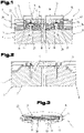
- FIG. 3 shows a detail of an embodiment variant of the device 1. It is possible within the scope of the invention for at least one stabilizing element 30 to be arranged in the elastic element 15.
- this stabilizing element 30, preferably several such stabilizing elements 30 distributed over the length of the expansion joint 2, can be formed from round steel. Other geometric, rod-shaped shapes are also possible.
- These stabilizing elements 30 reinforce the elastic element 15 and thus improve its mechanical properties.
- the stabilizing element 30 or the stabilizing elements 30 are supported on the holding element or elements 19 , 20 . In particular, the support takes place on the two legs 23, 24 of the holding elements 19, 20, as is shown in 3 is shown.
- Nuts and washers can be arranged on the ends facing the two legs 23, 24 of the holding elements 19, 20 in order to achieve a prestressing of the stabilizing elements 30 between the two legs 23, 24. It is also possible for a compression spring 31, for example a spiral spring, to be fitted over at least some of the stabilizing elements 30 in order to prevent the stabilizing elements from being untied from the casting of the elastic element 15.
- the stabilizing elements 30 are not embedded directly in the elastic element 15, but these stabilizing elements 30 are guided in a sleeve-shaped element 32, which in each case surrounds a stabilizing element 30 in the radial direction.
- stabilizing elements 30 it is possible for several stabilizing elements 30 to be arranged in a sleeve-shaped element 32, but this is not the preferred embodiment variant, since this means that volume for forming the elastic element 15 is lost.
- a spiral hose 33 for example made of plastic, can be provided instead of the sleeve-shaped elements 32 or additionally and surrounding them, which is cast in the elastic element 15 during its manufacture. This also makes it possible to transmit the expansions uniformly to the stabilizing elements 30 .
Description
Die Erfindung betrifft eine Vorrichtung zur Überbrückung einer Dehnfuge im Bereich einer Fahrbahn, umfassend eine Oberbaukonstruktion und eine Unterbaukonstruktion, wobei die Oberbaukonstruktion zumindest ein elastisches Element aufweist und die Unterbaukonstruktion eine Auflage für die Oberbaukonstruktion bildet.The invention relates to a device for bridging an expansion joint in the area of a roadway, comprising a superstructure and a substructure, the superstructure having at least one elastic element and the substructure forming a support for the superstructure.
Derartige Vorrichtungen zur Überbrückung von Dehnfugen zwischen Straßen und Brückenkonstruktionen sind aus dem Stand der Technik bereits bekannt.Such devices for bridging expansion joints between roads and bridge structures are already known from the prior art.
So beschreibt zum Beispiel die
Die
Aus der
Die
Eine weitere Dehnfugen-Überbrückungsvorrichtung mit vor Ort gegossenen elastischen Element und eingebettetem Halteprofil beschreibt die
Von der Firma COLAS GmbH, A-8101 Gratkorn, ist unter der Bezeichnung "Thorma® Joint" eine elastische Belagsdehnfuge bekannt, welche in Mattenbauweise aus polymervergütetem Bitumen und einem mineralischen Stützkörper aus Hartgestein gebildet ist.From the company COLAS GmbH, A-8101 Gratkorn, an elastic covering expansion joint is known under the name "Thorma ® Joint", which is formed in mat construction from polymer-improved bitumen and a mineral support body from hard rock.
Aufgabe vorliegender Erfindung ist es, eine verbesserte Vorrichtung zur Überbrückung einer Dehnfuge im Bereich einer Fahrbahn anzugeben. Diese Aufgabe wird durch die in Anspruch 1 angegebene Vorrichtung gelöst. Die erfindungsgemäße Dehnfugen-Überbrückungsvorrichtung zeichnet sich - neben anderen Merkmalen - somit insbesondere dadurch aus, dass in der Oberbaukonstruktion zumindest ein Halteelement angeordnet ist, das zumindest teilweise in dem elastischen Element eingebettet ist. Es wird damit eine Verstärkung des Verbundes zwischen der Oberbaukonstruktion und der Unterbaukonstruktion im vertikalen Bereich der Kontaktfläche zwischen dem elastischen Element der Oberbaukonstruktion und dem angrenzenden Straßenbelag erreicht, sodass diese Kontaktfläche entlastet wird und somit Abschälungen als Folge von Druck- oder Zugspannungen vermindert werden. Im horizontalen Bereich verbessert das zumindest eine Halteelement die Haftung des elastischen Elementes an der Unterbaukonstruktion. Es wird damit also eine verbesserte, mechanische Belastbarkeit der Vorrichtung erreicht, sodass diese eine längere Standzeit aufweist und damit Wartungsarbeiten und die damit verbundenen Kosten reduziert werden können.The object of the present invention is to specify an improved device for bridging an expansion joint in the area of a roadway. This object is achieved by the device specified in
Indem erfindungsgemäß das bzw. die Halteelement(e) durch ein Winkelprofil bzw. durch Winkelprofile gebildet sind, sind an diesem Halteelement bzw. diesen Haltelementen Schenkel vorhanden, die in das elastische Element reichen und damit die Anhaftung des Halteelementes bzw. der Halteelemente an dem elastischen Element verbessert werden kann, wodurch wiederum höhere Kräfte übertragbar sind.According to the invention, the holding element(s) are formed by an angle profile or angle profiles, legs are present on this holding element or these holding elements, which reach into the elastic element and thus the attachment of the holding element or the holding elements to the elastic Element can be improved, which in turn higher forces can be transmitted.
Dabei ist erfindungsgemäß vorgesehen, dass sich das Halteelement zumindest annähernd über die gesamte Länge der Oberbaukonstruktion durchgehend erstreckt. Mit anderen Worten ausgedrückt, erstreckt sich also das Halteelement zumindest annähernd über die gesamte Länge der Dehnfuge. Es wird damit nicht nur der Aufbau der Vorrichtung an sich vereinfacht - es erfolgt die Herstellung des elastischen Elementes vor Ort durch Gießen, wie dies nachstehend noch näher ausgeführt wird - sondern kann damit eine weitere Verbesserung der von der Dehnfuge aufnehmbaren, anliegenden Kräfte erreicht werden, indem sich diese Kräfte über eine größere Fläche innerhalb des elastischen Elementes verteilen und somit lokale Unterschiede in der Belastung des Halteelementes bzw. der Vorrichtung nicht bzw. vermindert zum Tragen kommen. Bevorzugt kann vorgesehen sein, dass das oder die Halteelement(e) zumindest eine Ausnehmung aufweisen, in die das elastische Element ragt. Es wird damit eine bessere Einbettung des Haltelementes oder der Halteelemente in dem elastischen Element erreicht, wodurch wiederum die mechanische Stabilität der Vorrichtung, insbesondere gegen Abschälungen, verbessert werden kann.It is provided according to the invention that the retaining element extends at least approximately over the entire length of the superstructure. In other words, the holding element extends at least approximately over the entire length of the expansion joint. It won't only the structure of the device itself is simplified - the elastic element is produced on site by casting, as will be explained in more detail below - but a further improvement in the forces that can be absorbed by the expansion joint can be achieved by these forces distributed over a larger area within the elastic element and thus local differences in the load on the holding element or the device do not have an effect or have a reduced effect. Provision can preferably be made for the holding element(s) to have at least one recess into which the elastic element projects. Better embedding of the holding element or the holding elements in the elastic element is thus achieved, which in turn can improve the mechanical stability of the device, in particular against peeling off.
In der erfindungsgemäßen Ausführung der Vorrichtung ist das elastische Element der Oberbaukonstruktion aus einem gießfähigen Kunstharz bzw. Kunststoff gebildet, indem es zumindest teilweise aus einem Polyharnstoff- bzw. einem Polyureasystem besteht. Das Polyharnstoff- bzw. das Polyureasystem weist dabei eine Härte nach Shore A von 55 bis 85 auf, die Zugfestigkeit des Polyharnstoff- bzw. des Polyureasystems nach DIN 53504 beträgt zwischen 10 und 30 N/mm2. Weiterhin weist das Polyharnstoff- bzw. das Polyureasystem eine Dehnung nach DIN 53504 zwischen 400 und 1200 % auf. Die Viskosität des Polyharnstoff- bzw. des Polyureasystems bei 23 °C beträgt zwischen 4000 und 6000 mPas. Es wird damit einerseits die einfache Herstellung der Vorrichtung auf der Baustelle verbessert, andererseits bleibt die Befahrbarkeit, anders als bei bituminösen Systemen, auch bei hohen klimatischen Temperaturen, zum Beispiel bei direkter Sonneneinstrahlung, bei denen bituminöse Systeme bereits erweichen, erhalten. Zudem ist ein Polyharnstoff- bzw. ein Polyureasystem verschleißfester als die im Stand der Technik bekannten Systeme auf Basis von Bitumen. Insbesondere durch die Verwendung eines Polyharnstoff- bzw. eines Polyureasystems werden auch die Spurrillenbildung, Verdrückungen und das Auslaufen der Oberfläche besser verhindert. Das Polyharnstoff- bzw. das Polyureasystem kann in einem weiten Temperaturbereich kalt eingebaut werden. Herkömmliche bituminöse Systeme müssen heiß eingebaut werden, was mit erheblichen Energieaufwand und hoher Lärmemission verbunden ist. Weiters können auch größere Dehnwege als bisher bewältigt, das heißt überbrückt werden.In the embodiment of the device according to the invention, the elastic element of the superstructure is formed from a castable synthetic resin or plastic, in that it consists at least partially of a polyurea or polyurea system. The polyurea or polyurea system has a Shore A hardness of 55 to 85, the tensile strength of the polyurea or polyurea system according to DIN 53504 is between 10 and 30 N/mm2. Furthermore, the polyurea or polyurea system has an elongation according to DIN 53504 between 400 and 1200%. The viscosity of the polyurea or polyurea system at 23 °C is between 4000 and 6000 mPas. On the one hand, this improves the simple manufacture of the device on the construction site, and on the other hand, unlike with bituminous systems, trafficability is maintained even at high climatic temperatures, for example in direct sunlight, at which bituminous systems already soften. In addition, a polyurea or polyurea system is more wear-resistant than the bitumen-based systems known in the prior art. In particular, the use of a polyurea or a polyurea system also better prevents the formation of ruts, crushing and surface leakage. The polyurea or polyurea system can be installed cold over a wide temperature range. Conventional bituminous systems have to be installed hot, which involves considerable energy consumption and high noise emissions. Furthermore, larger expansion distances than before can also be mastered, i.e. bridged.
Durch die Verwendung von einem Polyharnstoff- bzw. einem Polyureasystem zur Herstellung des elastischen Elementes ist es möglich, dass die Schichtdicke des elastischen Elementes maximal 60 mm beträgt. Damit ist dieses elastische Element im Gegensatz zu den am Markt befindlichen Asphaltdehnfugen eher dünn. Diese Verringerung der Schichtdicke hat den Vorteil, dass die Verformungskräfte geringer sind. Die Verformungskräfte, die bei Längenänderungen der Tragwerke auftreten (Zug/Druck), bewirken einerseits eine Belastung der angrenzenden Bauteile, wie Widerlager, Tragwerke, Brückenlager, andererseits innere Spannungen im Werkstoff des elastischen Elementes. Die verminderte Schichtdicke des elastischen Elementes erlaubt es daher, die angrenzenden und nachfolgenden Bauteile des Bauwerks kleiner und wirtschaftlicher herzustellen.By using a polyurea or a polyurea system to produce the elastic element, it is possible for the layer thickness of the elastic element to be a maximum of 60 mm. This elastic element is therefore rather thin in contrast to the asphalt expansion joints on the market. This reduction in layer thickness has the advantage that the deformation forces are lower. The deformation forces that occur when the length of the supporting structure changes (tension/compression) cause a load on the adjacent components such as abutments, supporting structures, bridge bearings on the one hand, and internal stresses in the material of the elastic element on the other. The reduced layer thickness of the elastic element therefore allows the adjacent and subsequent components of the structure to be made smaller and more economically.
Die Unterbaukonstruktion kann zumindest teilweise aus einem Werkstoff aus der Gruppe, umfassend Epoxydharze, Polymerbeton, Beton, Metalle, wie zum Beispiel Stahl, bestehen. Es wird damit eine kostengünstig herstellbare Unterbaukonstruktion zur Verfügung gestellt, die die erforderlichen starren Eigenschaften zur Unterstützung der Oberbaukonstruktion, das heißt insbesondere des elastischen Elementes, zur Verfügung stellt.The substructure can at least partially consist of a material from the group comprising epoxy resins, polymer concrete, concrete, metals such as steel. A substructure structure that can be produced at low cost is thus made available, which provides the necessary rigid properties for supporting the superstructure structure, that is to say in particular the elastic element.
Es ist bevorzugt, wenn das oder die Halteelement(e) mit zumindest einem Verbundanker mit der Unterbaukonstruktion verbunden ist bzw. sind. Durch diese Ausführungsvariante der Erfindung wird die Belastbarkeit der Vorrichtung weiter erhöht, indem über die Befestigung des Halteelementes bzw. der Halteelemente an der Unterbaukonstruktion, also dem Tragwerk, Abschälungen im Bereich des elastischen Elementes besser verhindert werden können. Weiters wird damit, nachdem das Halteelement bzw. die Halteelemente mit ihrer Oberseite in das elastische Element hineinragen und somit auch der oder die Verbundanker mit seinem bzw. ihrem einen Ende in das elastische Element hineinragt bzw. hineinragen, eine bessere Verbundwirkung erreicht, die zur Abtragung der an der Haftfläche zwischen der Oberbaukonstruktion und der Unterbaukonstruktion auftretenden Druck- bzw. Zugspannungen beiträgt.It is preferred if the holding element(s) is/are connected to the substructure with at least one chemical anchor. This embodiment variant of the invention further increases the load-bearing capacity of the device in that peeling off in the area of the elastic element can be better prevented by fastening the holding element or the holding elements to the substructure, ie the supporting structure. Furthermore, after the holding element or the holding elements protrude with their upper side into the elastic element and thus also the shear connector or anchors protrude or protrude with one end into the elastic element, a better composite effect is achieved, which leads to removal the compressive and tensile stresses occurring on the adhesive surface between the superstructure and the substructure.
Gemäß einer weiteren Ausführungsvariante ist vorgesehen, dass an dem elastischen Element an einer in Richtung auf die Unterbaukonstruktion weisenden Unterseite zumindest eine, sich bevorzugt über zumindest annährend die gesamte Länge der Oberbaukonstruktion durchgehend erstreckende, Schubnase ausgebildet ist. Es wird damit einerseits eine mechanische Verbindung zwischen dem elastischen Element und der Unterbaukonstruktion geschaffen, wodurch die Kontaktfläche zwischen der Oberbaukonstruktion, das heißt dem elastischen Element, und der Unterbaukonstruktion von Schubspannungen entlastet wird. Andererseits wird damit diese Kontaktfläche vergrößert, womit eine Reduktion der Haftspannungen erreicht werden kann.According to a further embodiment variant it is provided that at least one sliding lug is formed on the elastic element on an underside pointing in the direction of the substructure, preferably extending continuously over at least approximately the entire length of the superstructure. On the one hand, a mechanical connection is thus created between the elastic element and the substructure, as a result of which the contact surface between the superstructure, ie the elastic element, and the substructure is relieved of shear stresses. On the other hand, this enlarges the contact area, which means that a reduction in the adhesive stresses can be achieved.
In dem elastischen Element kann zumindest ein Stabilisierungselement angeordnet sein. Es wird damit erreicht, dass das elastische Element Dehn- bzw. Verschiebewege aufnehmen kann, die wesentlich größer sind als die einfacher, elastischer Belagsdehnfugen aus bituminösen Werkstoffen.At least one stabilizing element can be arranged in the elastic element. This means that the elastic element can absorb expansion or displacement paths that are significantly larger than those of simple, elastic covering expansion joints made of bituminous materials.
Zusätzlich kann das Stabilisierungselement bzw. können die Stabilisierungselemente gemäß einer weiteren Ausführungsvariante der Vorrichtung ein hülsenförmiges Element bzw. hül-senförmige Elemente aufweisen, in dem das Stabilisierungselement oder in denen die Stabilisierungselemente angeordnet sind. Das hülsenförmige Element bzw. die hülsenförmigen Elemente wirken als Schubhülsen, in denen das Stabilisierungselement bzw. die Stabilisierungselemente geführt sind und in denen sich diese bewegen können, wodurch die Wirkung der Stabilisierungselemente als Bewehrung für das elastische Element der Oberbaukonstruktion verbessert werden kann.In addition, according to a further embodiment of the device, the stabilizing element or elements can have a sleeve-shaped element or elements, in which the stabilizing element or in which the stabilizing elements are arranged. The sleeve-shaped element or elements act as thrust sleeves in which the stabilizing element or elements are guided and in which they can move, thereby improving the effect of the stabilizing elements as reinforcement for the elastic element of the superstructure can be.
Bevorzugt stützt sich das oder stützen sich die Stabilisierungselement(e) an dem Haltelement oder an den Halteelementen ab, wodurch die Stabilisierung der Dehnfuge über diese Stabilisierungselemente und die Halteelemente verbessert werden kann.The stabilizing element(s) is/are preferably supported on the holding element or on the holding elements, as a result of which the stabilization of the expansion joint can be improved via these stabilizing elements and the holding elements.
Dabei ist es von Vorteil, wenn sich das oder die Stabilisierungselement(e) zwischen den nach oben abstehenden Schenkeln der Winkelprofile, das heißt in das elastische Element hineinragenden Schenkel der Winkelprofile, erstreckt, insbesondere an diesen Schenkeln anliegt, um eine weitere Verbesserung der Stabilisierungsfunktion durch das Zusammenwirken der Stabilisierungselemente mit dem Halteelement bzw. den Halteelementen zu erreichen.It is advantageous if the stabilizing element(s) extends between the upwardly protruding legs of the angle profiles, i.e. the legs of the angle profiles projecting into the elastic element, and in particular rests against these legs in order to further improve the stabilization function to achieve the interaction of the stabilizing elements with the holding element or the holding elements.
Es kann weiters vorgesehen sein, dass das oder die Stabilisierungselement(e) eine Druckfeder aufweist oder aufweisen, um ein Ausknüpfen der Stabilisierungselemente aus dem elastischen Element zu verhindern.Provision can furthermore be made for the stabilizing element(s) to have or have a compression spring in order to prevent the stabilizing elements from being untied from the elastic element.
Gemäß einer weiteren Ausführungsvariante ist vorgesehen, dass das oder die Stabilisierungselement(e) oder das oder die hülsenförmigen Element(e) zumindest teilweise von einem Spiralschlauch umgeben sind. Dieser ist insbesondere in dem elastischen Element eingegossen und bewirkt, dass Dehnungen gleichmäßig auf das Stabilisierungselement bzw. die Stabilisierungselemente übertragen werden. Zudem wird damit die Reibung zum elastischen Element, also beispielsweise dem Polyurethanverguss, verringert bzw. vermieden.According to a further embodiment, it is provided that the stabilizing element(s) or the sleeve-shaped element(s) are at least partially surrounded by a spiral hose. This is cast in particular in the elastic element and causes expansions to be evenly transmitted to the stabilization element or elements. In addition, this reduces or avoids friction with the elastic element, for example the polyurethane casting.
Zum besseren Verständnis der Erfindung wird diese anhand der nachfolgenden Figuren näher erläutert.For a better understanding of the invention, it is explained in more detail with reference to the following figures.
Es zeigen jeweils in schematisch vereinfachter Darstellung:
- Fig. 1
- eine erste Ausführungsvariante einer erfindungsgemäßen Vorrichtung in Seitenansicht geschnitten;
- Fig. 2
- eine andere Ausführungsvariante der Vorrichtung in Seitenansicht geschnitten;
- Fig. 3
- ein Detail aus einer erfindungsgemäßen Vorrichtung im Bereich eines Stabilisierungselementes.
- 1
- a first embodiment of a device according to the invention in side view;
- 2
- another embodiment variant of the device in side view;
- 3
- a detail of a device according to the invention in the area of a stabilizing element.
Einführend sei festgehalten, dass in den unterschiedlich beschriebenen Ausführungsformen gleiche Teile mit gleichen Bezugszeichen bzw. gleichen Bauteilbezeichnungen versehen werden, wobei die in der gesamten Beschreibung enthaltenen Offenbarungen sinngemäß auf gleiche Teile mit gleichen Bezugszeichen bzw. gleichen Bauteilbezeichnungen übertragen werden können. Auch sind die in der Beschreibung gewählten Lageangaben, wie z.B. oben, unten, seitlich usw. auf die unmittelbar beschriebene sowie dargestellte Figur bezogen und sind bei einer Lageänderung sinngemäß auf die neue Lage zu übertragen.As an introduction, it should be noted that in the differently described embodiments, the same parts are provided with the same reference numbers or the same component designations, it being possible for the disclosures contained throughout the description to be applied to the same parts with the same reference numbers or the same component designations. The position information selected in the description, such as top, bottom, side, etc., refers to the figure directly described and shown and must be transferred to the new position in the event of a change of position.
Die Vorrichtung 1 weist eine Oberbaukonstruktion 5 und eine Unterbaukonstruktion 6 auf.The
Die Unterbaukonstruktion 6 umfasst bei dieser Ausführungsvariante zwei voneinander beabstandete Bodenelemente 7, 8 die bis in den Bereich der Dehnfuge 2 reichen. Auf diesen Bodenelementen 7, 8 ist jeweils eine Unterbausschwelle 9, 10 angeordnet, insbesondere mit den Bodenelementen 7 bzw. 8 verbunden.In this variant, the
Die Bodenelemente 7, 8 können beispielsweise aus einem Beton, wie er im Straßenbau verwendet wird, bestehen.The
Die beiden Unterbauschwellen 9, 10 sind zwischen den Fahrbahnen 3, 4 in der Dehnfuge 2 angeordnet und können insbesondere aus einem Epoxydharz oder einem Polymerbeton oder einem anderen, geeigneten, starren Baustoff hergestellt sein. Insbesondere ist es auch möglich, diese beiden Unterbauschwellen 9, 10 vor Ort auf der Baustelle herzustellen, sofern nicht bereits vorgefertigte Elemente hierfür eingesetzt werden.The two
Die Unterbaukonstruktion 6 ist bezogen auf die Oberbaukonstruktion 5 starr ausgeführt. Mit dem Begriff "starr" im Sinne der Erfindung ist gemeint, dass diese Unterbaukonstruktion 6 bzw. deren Bestandteile mit Ausnahme von Wärmedehnungen bzw. Schrumpfungen keine weiteren Dimensionsänderungen während des Betriebes der Vorrichtung 1 erfahren.The
Die beiden Unterbauschwellen 9, 10 weisen bevorzugt eine Breite 11, 12 auf, die so bemessen ist, dass ein durch die beabstandete Anordnung der beiden Bodenelemente 7, 8 zueinander gebildeter Spalt nicht eingeschnürt wird, also bevorzugt die aufeinander zuweisenden Stirnflächen der Unterbauschwellen 9, 10 jeweils fluchtend mit den jeweiligen Stirnflächen der beiden aufeinander zuweisenden Bodenelemente 7, 8 angeordnet sind, wie dies in
Im Anschlussbereich an die Dehnfuge 2 und teilweise in die Dehnfuge 2 reichend, ist zwischen den Fahrbahnen 3, 4 und den Bodenelementen 7, 8 jeweils ein Dichtelement 13, 14, beispielsweise eine Dichtfolie, wie diese aus dem Stand der Technik bekannt ist, angeordnet.In the connection area to the
Die Oberbaukonstruktion 5 umfasst ein elastisches Element 15, welches sich zwischen den beiden Fahrbahnen 3, 4 und die Dehnfuge 2 überbrückend erstreckt. Insbesondere ist dieses elastische Element an der Oberseite fluchtend mit den Oberflächen der Fahrbahnen 3, 4 ausgebildet, sodass also im Bereich der Dehnfuge 2 fahrbahnseitig keine bzw. keine wesentliche, den Fahrkomfort beeinflussende Erhöhung oder Vertiefung vorhanden ist.The superstructure 5 comprises an
Das elastische Element 15 stützt sich auf den Unterbauschwellen 9, 10 ab. Nachdem das elastische Element 15 in Gussbauweise aus einem Kunstharz bzw. Kunststoff direkt auf der Baustelle, hergestellt wird, besteht die Möglichkeit, dass sich das Material des elastischen Elementes 15 zumindest in jenen Bereichen, in denen dieses elastische Element 15 direkt an den Unterbauschwellen 9, 10 unter Ausbildung einer Kontaktfläche 16 anliegt, verbindet.The
Für das elastische Element 15 wird ein kalthärtendes, giessbares Kunstharz bzw. ein kalthärtender, giessbarer Kunststoff verwendet, nämlich ein Polyharnstoff- bzw. ein Polyureasystem, um das elastische Element 15 direkt auf der Baustelle durch Gießen herstellen zu können. Als Polyharnstoff- bzw. Polyureasystem wird ein Polyharnstoff- bzw. ein Polyureasystem mit einer der Verwendung angepassten Härte verwendet, so dass einerseits die Verformung mit möglichst geringem Widerstand ermöglicht wird und andererseits die Belastungen aus dem Verkehr möglichst geringe Verformungen zur Folge haben. Beispielsweise kann ein 2K-Polyureasystem verwendet werden. Das Polyharnstoff- bzw. das Polyureasystem weist eine Härte nach Shore A von 55 bis 85 auf. Die Zugfestigkeit des Polyharnstoff- bzw. des Polyureasystems nach DIN 53504 beträgt zwischen 10 und 30 N/mm2. Des Weiteren weist das Polyharnstoff- bzw. das Polyureasystem eine Dehnung nach DIN 53504 zwischen 400 und 1200 % auf. Insbesondere ist es von Vorteil, wenn ein Polyharnstoff - bzw. ein Polyureasystem mit thixotropen Eigenschaften verwendet wird. Die Viskosität des Polyharnstoff - bzw. des Polyureasystems beträgt bei 23 °C zwischen 4000 und 6000 mPas.A cold-curing, castable synthetic resin or a cold-curing, castable plastic is used for the
Zur Verbesserung der Haftfähigkeit kann vorab auch ein Haftvermittler, ein so genannter Primer, aufgetragen werden.To improve adhesion, an adhesion promoter, a so-called primer, can also be applied beforehand.
Im Bereich des Spaltes der in horizontaler Richtung zwischen den Unterbauschwellen 9, 10 bzw. Bodenelementen 7, 8 ausgebildet wird, ist auf den Unterbauschwellen 9, 10 ein Abdeckelement 17 angeordnet, welches diesen Spalt insbesondere feuchtigkeitsdicht abdeckt. Dieses Abdeckelement 17 kann beispielsweise aus einem Metall oder Kunststoffstreifen bestehen. Bevorzugt weist das Abdeckelement 17 ein Zentrierelement 18 für den genaueren Einbau dieses Abdeckelementes 17 bzw. zur Erhöhung der Betriebssicherheit der Vorrichtung 1 auf, wobei das Zentrierelement 18 in den Spalt zwischen den beiden Bodenelementen 7, 8 bzw. den Unterbauschwellen 9, 10 ragt.In the area of the gap formed in the horizontal direction between the
Zur Verbesserung des Verbundes zwischen dem elastischen Element 15 und den Unterbauschwellen 9, 10 bei der Ausführungsvariante nach
Die Halteelemente 19, 20 sind als Winkelelemente mit einer Basis 21, 22 sowie von der Basis 21, 22 zumindest annähernd rechtwinkelig nach oben in das elastische Element 15 und in diesem eingebettet, abstehenden Schenkeln 23, 24. Die beiden Schenkeln 23, 24 dabei, wie dargestellt, bevorzugt jeweils den Fahrbahnen 3, 4 zugewandt.The holding
Vorzugsweise bestehen die Halteelemente 19, 20 aus einem Metall, beispielsweise Stahl.The holding
Zur Verbesserung des Verbundes zwischen dem elastischen Element 15 und den Haltelementen 19, 20 können letztere zumindest eine Ausnehmung aufweisen, bevorzugt sind diese als Lochblech bzw. gelochtes Blech ausgeführt, um damit während der Herstellung des elastischen Elementes 15 aus dem gießfähigen, härtbaren Kunstharz bzw. dem Kunststoff dieses bzw. diesen in diese Ausnehmungen eintreten zu lassen.To improve the connection between the
Die beiden Halteelemente 19, 20 erstrecken sich über die gesamte Länge der Dehnfuge 2, welche sich in Richtung der Blickrichtung auf die Ausführungsvariante nach
Um den Verbund zwischen den Halteelementen 19, 20 und der Unterbaukonstruktion 6 zu verbessern, können die Halteelemente 19, 20 mit jeweils zumindest einem Verbundanker 25, 26 versehen sein, wobei sich diese Verbundanker 25, 26 aus dem elastischen Element 15 bis zumindest in den Bereich der Unterbauschwellen 9 bzw. 10, bevorzugt bis in den Bereich der Bodenelemente 7 bzw. 8, wie in
Obwohl es möglich ist, dass nur jeweils ein Verbundanker 25, 26 pro Seite der Dehnfuge 2 angeordnet ist, ist vorzugsweise im Rahmen der Erfindung vorgesehen, dass in Längsrichtung der Dehnfuge 2 mehrere derartige Verbundanker 25, 26 nebeneinander und bevorzugt in regelmäßigen Abständen zueinander angeordnet werden.Although it is possible that only one
In der Ausführungsvariante, bei der mehrere Halteelemente 19, 20 in Richtung der Längserstreckung der Dehnfuge 2 nebeneinander angeordnet sind, weist bevorzugt jedes dieser Halteelemente 19, 20 einen eigenen Verbundanker 25, 26 auf.In the embodiment variant in which several holding
Die Verbundanker 25, 26 bestehen vorzugsweise aus einem Metall, insbesondere aus Stahl.The chemical anchors 25, 26 are preferably made of a metal, in particular steel.
Gemäß einer weiteren Ausführungsvariante der Erfindung ist vorgesehen, dass das elastische Element 15 jeweils beidseits der Dehnfuge 2, also auf jeder Seite im Bereich neben dem ausgebildeten Spaltes zwischen den Unterbauschwellen 9, 10 bzw. Bodenelementen 7, 8, zumindest eine Schubnase 27 auf. Diese beiden Schubnasen 27, 28 werden während der Herstellung des elastischen Elementes 15 durch das Ausgießen der Dehnfuge 2 mit dem Kunstharz bzw. dem Kunststoff hergestellt, wozu in den Unterbauschwellen 9, 10 entsprechende nutartige Rillen vorgesehen sind, um das Austreten bzw. Eintreten des Kunstharzes bzw. des Kunststoffes in diese Nuten zu ermöglichen. Es wird damit ermöglicht, dass diese Schubnasen 27, 28 einstückig mit dem elastischen Element 15 hergestellt werden. Das Eintreten des Kunstharzes bzw. des Kunststoffes in die Nuten der Unterbauschwellen 9, 10 wird durch die Ausnehmungen in den Haltelementen 19, 20 ermöglich.According to a further embodiment variant of the invention, it is provided that the
Es besteht im Rahmen der Erfindung aber selbstverständlich auch die Möglichkeit, dass in Fahrtrichtung mehrere derartige Schubnasen 27, 28 hintereinander innerhalb einer der Unterbauschwellen 9, 10 angeordnet sind.Within the scope of the invention, however, there is of course also the possibility that several
Bevorzugt erstrecken sich diese Schubnasen 27, 28 wiederum durchgehend über die gesamt Länge der Dehnfuge 2 bzw. des elastischen Elementes 15, es besteht jedoch auch die Möglichkeit, mehrere derartige Schubnasen 27, 28 nebeneinander in Richtung der Länge der Dehnfuge 2 anzuordnen.Preferably, these push lugs 27, 28 in turn extend continuously over the entire length of the
Des Weiteren können die Schubnasen 27, 28 einen rechteckigen Querschnitt, in Richtung der Länge der Dehnfuge 2 betrachtet, aufweisen, ebenso können die Querschnitte der nutartigen Rillen zumindest eine Hinterschneidung aufweisen, wodurch ein besserer Verbund erreicht wird, indem das Kunstharz bzw. der Kunststoff diese Hinterschneidungen ausfüllt. Die Schubnasen 27, 28 können aber auch quadratische, polygonale, etc. Querschnitte aufweisen.Furthermore, the thrust lugs 27, 28 can have a rectangular cross section, viewed in the direction of the length of the
In
Bezüglich der weiteren Details dieser Ausführungsvariante der Erfindung sei auf die Ausführungen zu
Vorzugsweise weist das elastische Element 15 eine Schichtdichte 29 (
In der bevorzugten Ausführungsvariante sind die Stabilisierungselemente 30 nicht direkt im elastischen Element 15 eingebettet, sondern sind diese Stabilisierungselemente 30 in einem hülsenförmigen Element 32, welches jeweils ein Stabilisierungselement 30 in radialer Richtung umgibt, geführt.In the preferred embodiment variant, the stabilizing
Es besteht die Möglichkeit, dass in einem hülsenförmigen Element 32 mehrere Stabilisierungselemente 30 angeordnet werden, jedoch ist dies nicht die bevorzugte Ausführungsvariante, da damit Volumen zur Ausbildung des elastischen Elementes 15 verloren geht.It is possible for several stabilizing
Um Reibungen zwischen dem elastischen Element 15 zu verhindern, kann vorgesehen werden, dass anstelle der hülsenförmigen Elemente 32 oder zusätzlich und diese umgebend ein Spiralschlauch 33, beispielsweise aus Kunststoff vorgesehen wird, welcher in dem elastischen Element 15, während dessen Herstellung, eingegossen wird. Es wird damit auch ermöglicht, die Dehnungen gleichmäßig auf die Stabilisierungselemente 30 zu übertragen.In order to prevent friction between the
Die Ausführungsbeispiele zeigen mögliche Ausführungsvarianten der Vorrichtung 1, wobei an dieser Stelle bemerkt sei, dass die Erfindung nicht auf die speziell dargestellten Ausführungsvarianten derselben eingeschränkt ist, sondern gemäß dem Schutzumfang, definiert durch die beiliegenden Patentansprüche. Auch diverse Kombinationen der einzelnen Ausführungsvarianten untereinander sind möglich und diese Variationsmöglichkeit aufgrund der Lehre zum technischen Handeln durch gegenständliche Erfindung im Können des auf diesem technischen Gebiet tätigen Fachmannes liegt.The embodiments show possible variants of the
Der Ordnung halber sei abschließend darauf hingewiesen, dass zum besseren Verständnis des Aufbaus der Vorrichtung 1 diese bzw. deren Bestandteile teilweise unmaßstäblich und/oder vergrößert und/oder verkleinert dargestellt wurden.Finally, for the sake of order, it should be pointed out that, for a better understanding of the structure of the
- 11
- Vorrichtungcontraption
- 22
- Dehnfugeexpansion joint
- 33
- Fahrbahnroadway
- 44
- Fahrbahnroadway
- 55
- Oberbaukonstruktionsuperstructure
- 66
- Unterbaukonstruktionsubstructure
- 77
- Bodenelementfloor element
- 88th
- Bodenelementfloor element
- 99
- Unterbauschwellesubstructure threshold
- 1010
- Unterbauschwellesubstructure threshold
- 1111
- BreiteBroad
- 1212
- BreiteBroad
- 1313
- Dichtelementsealing element
- 1414
- Dichtelementsealing element
- 1515
- Elementelement
- 1616
- Kontaktflächecontact surface
- 1717
- Abdeckelementcover element
- 1818
- Zentrierelementcentering element
- 1919
- Halteelementholding element
- 2020
- Halteelementholding element
- 2121
- BasisBase
- 2222
- BasisBase
- 2323
- Schenkelleg
- 2424
- Schenkelleg
- 2525
- Verbundankerchemical anchor
- 2626
- Verbundankerchemical anchor
- 2727
- Schubnasethrust nose
- 2828
- Schubnasethrust nose
- 2929
- Schichtdickelayer thickness
- 3030
- Stabilisierungselementstabilization element
- 3131
- Druckfedercompression spring
- 3232
- Elementelement
- 3333
- Spiralschlauchspiral hose
Claims (12)
- A device (1) for bridging an expansion joint (2) in the region of a carriageway, comprising a superstructure (5) and a substructure (6), having the following features:the substructure (6) forms a support for the superstructure (5);the superstructure (5) has at least one resilient element (15);at least one holding element (19, 20) which is at least partially embedded in the resilient element (15) is arranged in the superstructure (5);the at least one holding element (19, 20) is formed by an angle profile or by angle profiles and is arranged so as to extend continuously over at least approximately the entire length of the superstructure (5) ;the resilient element (15) of the superstructure (5) is cast in situ;characterized in thatthe resilient element (15) consists of a cold-setting castable synthetic resin or a cold-setting castable plastics in the form of a polycarbamide system or polyurea system,wherein- the polycarbamide system or the polyurea system has a Shore A hardness of 55 to 85,- the tensile strength of the polycarbamide system or the polyurea system according to DIN 53504 is between 10 and 30 N/mm2,- the polycarbamide system or the polyurea system has an expansion according to DIN 53504 of between 400 and 1200%, and- the viscosity of the polycarbamide system or the polyurea system at 23 °C is between 4000 and 6000 mPas.
- The device (1) according to Claim 1, characterized in that the holding element (s) (19, 20) has or have at least one recess into which the resilient element (15) protrudes.
- The device (1) according to one of Claims 1 or 2, characterized in that the resilient element (15) has a layer thickness (29) of a maximum of 60 mm.
- The device (1) according to one of Claims 1 to 3, characterized in that the substructure (6) at least partially consists of at least one material from the group comprising epoxy resins, polymer concrete, concrete, steel.
- The device (1) according to one of Claims 1 to 4, characterized in that the holding element(s) (19, 20) is or are connected by at least one shear connector (25, 26) to the substructure (6).
- The device (1) according to one of Claims 1 to 5, characterized in that at least one shear key (27, 28) is configured on the resilient element (15) on a lower face which faces in the direction of the substructure (6), preferably so as to extend continuously over at least approximately the entire length of the superstructure (5).
- The device (1) according to one of Claims 1 to 6, characterized in that at least one stabilizing element (30) is arranged in the resilient element (15).
- The device (1) according to Claim 7, characterized in that the stabilizing element(s) (30) is or are arranged in one or more sleeve-shaped element(s) (32).
- The device (1) according to Claim 7 or 8, characterized in that the stabilizing element(s) (30) is or are supported on the holding element (s) (19, 20) .
- The device (1) according to one of Claims 7 to 9, characterized in that the stabilizing element(s) (30) extends or extend between upwardly protruding arms (23, 24) of the angle profiles.
- The device (1) according to one of Claims 7 to 10, characterized in that the stabilizing element(s) (30) has or have in each case a compression spring (31).
- The device (1) according to one of Claims 7 to 11, characterized in that the stabilizing element(s) (30) or the sleeve-shaped element (s) (32) is or are at least partially surrounded by a spiral tube (33).
Applications Claiming Priority (2)
| Application Number | Priority Date | Filing Date | Title |
|---|---|---|---|
| ATA1541/2009A AT508847B1 (en) | 2009-09-30 | 2009-09-30 | DEVICE FOR BRIDGING AN EXTENSION |
| PCT/AT2010/000359 WO2011038434A2 (en) | 2009-09-30 | 2010-09-30 | Device for bridging an expansion joint |
Publications (3)
| Publication Number | Publication Date |
|---|---|
| EP2483477A2 EP2483477A2 (en) | 2012-08-08 |
| EP2483477B1 EP2483477B1 (en) | 2020-02-19 |
| EP2483477B2 true EP2483477B2 (en) | 2023-01-18 |
Family
ID=43608358
Family Applications (1)
| Application Number | Title | Priority Date | Filing Date |
|---|---|---|---|
| EP10776260.1A Active EP2483477B2 (en) | 2009-09-30 | 2010-09-30 | Device for bridging an expansion joint |
Country Status (8)
| Country | Link |
|---|---|
| US (1) | US8671489B2 (en) |
| EP (1) | EP2483477B2 (en) |
| JP (1) | JP6077304B2 (en) |
| KR (1) | KR20120135399A (en) |
| AT (1) | AT508847B1 (en) |
| DK (1) | DK2483477T4 (en) |
| RU (1) | RU2558557C2 (en) |
| WO (1) | WO2011038434A2 (en) |
Families Citing this family (17)
| Publication number | Priority date | Publication date | Assignee | Title |
|---|---|---|---|---|
| CN102561146A (en) * | 2012-02-10 | 2012-07-11 | 成都市新筑路桥机械股份有限公司 | Seamless elastomer telescoping device |
| CN103205922A (en) * | 2013-05-06 | 2013-07-17 | 成都市新筑路桥机械股份有限公司 | Stable element for seamless elastomer extension device |
| ES2534230B1 (en) * | 2013-10-18 | 2015-11-11 | Ingeturarte Sl | Transition slab between the stirrup and the bridge board with long-life expansion and contraction joints, and absorption methods of the expansion and contraction movements of the bridge board |
| EP2865822B1 (en) * | 2013-10-24 | 2017-03-22 | GCP Applied Technologies Inc. | Anti-snaking swellable water-stops |
| CN104034611B (en) * | 2014-04-18 | 2016-05-11 | 武汉理工大学 | Bridge is seamless expanded joint material fatigue cracking analog detection method and testing equipment thereof |
| CN104018425B (en) * | 2014-06-24 | 2016-10-26 | 宁波路宝科技实业集团有限公司 | A kind of quick-replaceable bridge expansion joint installation and installation method thereof |
| JP6396770B2 (en) * | 2014-11-19 | 2018-09-26 | 中日本ハイウェイ・メンテナンス中央株式会社 | Road floor slab joint structure and construction method |
| ITUB20152883A1 (en) * | 2015-08-05 | 2017-02-05 | Edil Noli Srl | MODULAR PREFABRICATED JOINT, PARTICULARLY FOR INDUSTRIAL FLOORS AND METHOD FOR ITS PRODUCTION |
| RU2596847C1 (en) * | 2015-09-29 | 2016-09-10 | Федеральное государственное бюджетное образовательное учреждение высшего профессионального образования "Томский государственный архитектурно-строительный университет" (ТГАСУ) | Expansion joint |
| CN105735121B (en) * | 2016-04-15 | 2018-02-06 | 山东省建设建工(集团)有限责任公司 | A kind of covering mechanism for bridge expanssion joint |
| US9850626B2 (en) | 2016-05-16 | 2017-12-26 | LTBB Marketing, LLC | Expansion joint seals and methods for manufacturing the same |
| ES2877370T3 (en) * | 2019-01-14 | 2021-11-16 | Migua Fugensysteme Gmbh | Junction bridge device |
| JP7103647B2 (en) * | 2019-02-15 | 2022-07-20 | ライノジャパン株式会社 | Road repair structure equipped with telescopic device and repair method |
| CN110792035B (en) * | 2019-11-13 | 2021-05-25 | 成都市新筑路桥机械股份有限公司 | Reinforced seamless elastomer expansion device and construction method thereof |
| RU196838U1 (en) * | 2020-01-10 | 2020-03-17 | Общество с ограниченной ответственностью "ЭластоБетон" | DEFORMATION SEAM OF BRIDGE STRUCTURES |
| CN112721001B (en) * | 2021-03-31 | 2021-06-25 | 中国铁道科学研究院集团有限公司铁道建筑研究所 | Complete equipment and system for production and detection of polyurethane track bed blocks and use method |
| DE102021006143A1 (en) | 2021-12-13 | 2023-06-15 | Mageba Services & Technology Ag | Driveable structure |
Citations (9)
| Publication number | Priority date | Publication date | Assignee | Title |
|---|---|---|---|---|
| FR1380667A (en) † | 1963-10-21 | 1964-12-04 | Teroson Et Prot Chimiqque | Elastic expansion joint, cast, for engineering structures |
| US3520236A (en) † | 1967-03-03 | 1970-07-14 | Etienne Sequaris | Means for covering and rendering waterproof expansion joints for road bridges and other civil engineering constructions |
| US3822428A (en) † | 1972-07-19 | 1974-07-09 | Stog Kg Ind & Rohrleitung | Joint inserts for bridging expansion joints |
| DE2520791B1 (en) † | 1975-05-09 | 1976-03-18 | Wsw Stahl & Wasserbau Gmbh | Adhesive bonded expansion joint for roads - has adhesive bonded seat for cover plate of high wear resistance |
| US4319855A (en) † | 1978-09-28 | 1982-03-16 | Kober Ag | Highway expansion joint |
| JPS59134205A (en) † | 1983-01-20 | 1984-08-01 | 清水 惣一郎 | Structure expansion joint having float preventing apparatus |
| GB2293396A (en) † | 1994-09-26 | 1996-03-27 | Btps Services Sa | Joint for joining two elements of a road |
| US5649784A (en) † | 1995-06-16 | 1997-07-22 | Pavetech International, Inc. | Expansion joint system and method of making |
| JP2002348810A (en) † | 2001-05-23 | 2002-12-04 | Sanyo Kagaku Corp | Embedded joint |
Family Cites Families (33)
| Publication number | Priority date | Publication date | Assignee | Title |
|---|---|---|---|---|
| US1977496A (en) * | 1931-09-28 | 1934-10-16 | Nat Wood Products Co | Floor expansion joint |
| DE1184368B (en) * | 1958-10-30 | 1964-12-31 | Rheinstahl Union Brueckenbau | Process for pre-tensioning and installing a joint insert for expansion joints in streets or sidewalks as well as joint insert for performing the process |
| US3880540A (en) * | 1971-03-08 | 1975-04-29 | Brown Co D S | Modular expansion joint |
| GB1318805A (en) * | 1971-10-08 | 1973-05-31 | Invernizzi L | Expansion joints in pre-stressed reinforced concrete bridges |
| US3778954A (en) * | 1972-09-07 | 1973-12-18 | Johns Manville | Method of replacing a damaged bulkhead panel |
| FR2442299A1 (en) * | 1978-11-27 | 1980-06-20 | Freyssinet Int Stup | Expansion joint for road slab supports - has tensioned metal leaf fixing adjacent supports and bolted between slabs |
| ATE13205T1 (en) * | 1982-02-12 | 1985-05-15 | Kober Ag | JOINT COVERING. |
| DE3225304A1 (en) | 1982-07-07 | 1984-02-02 | Kober AG, 8750 Glarus | WATERPROOF EXPANSION COVER IN ROADWAYS |
| JPS5952002A (en) * | 1982-09-17 | 1984-03-26 | 日本奥アンツ−カ株式会社 | Paving method |
| JPS6136402A (en) * | 1984-07-30 | 1986-02-21 | ジャパンコンステック株式会社 | Continuous pavement of bridge surface |
| DE3739717C1 (en) | 1987-11-24 | 1989-03-16 | Kober Ag | Device for bridging expansion joints |
| FR2661235B1 (en) * | 1990-04-23 | 1992-07-31 | Traitement Indl Residus Urbains | BEAM FORMING EXPANSION JOINT BETWEEN TWO CLIMBING FIREPLACES ATTACHED, WITH ALTERNATIVELY FIXED AND MOBILE BARS. |
| DE4114507C2 (en) * | 1991-05-03 | 1997-09-11 | Chemwell Chemie Gmbh | Sound-insulating bridging of expansion joints |
| JPH0567605U (en) * | 1992-02-19 | 1993-09-07 | コニシ株式会社 | Expansion joint for road |
| US5297372A (en) * | 1992-06-09 | 1994-03-29 | Pawling Corporation | Elastomeric sealing system for architectural joints |
| FR2717512B1 (en) | 1994-03-21 | 1996-05-31 | Philippe Chapuis | Leaf pavement joint. |
| JP2564104B2 (en) * | 1994-10-21 | 1996-12-18 | 日本伸縮装置工業株式会社 | Road bridge fittings |
| RU2085648C1 (en) * | 1995-01-06 | 1997-07-27 | Мелик-Багдасаров Михаил Саркисович | Permanent way |
| CH691496A5 (en) * | 1996-01-24 | 2001-07-31 | Rsag Reparatur Und Sanierungst | Connection construction for expanding or contracting components of road or bridge; has elastic connection layer, which has integrated flexible movement spiral spring fixed to components |
| DE19602982C1 (en) * | 1996-01-27 | 1997-01-09 | Migua Fugensysteme Gmbh | Sealing device for an expansion joint |
| US6668412B1 (en) * | 1997-05-29 | 2003-12-30 | Board Of Regents Of University Of Nebraska | Continuous prestressed concrete bridge deck subpanel system |
| JP4272293B2 (en) * | 1998-03-18 | 2009-06-03 | 北川辺町 | Normal temperature mixture for elastic pavement and elastic pavement using the same |
| CN1258330A (en) | 1998-03-18 | 2000-06-28 | 日沥株式会社 | Mixture of flexible pavement usable at ordinary temp. |
| RU2122063C1 (en) * | 1998-03-24 | 1998-11-20 | Открытое акционерное общество "Мостотрест" | Functional joint |
| FR2777921B1 (en) * | 1998-04-09 | 2000-09-01 | Rca Corp | EXPANSION JOINTS FOR PAVEMENTS INCORPORATING FIBROUS MATERIALS |
| FR2792012B1 (en) * | 1999-04-09 | 2002-06-07 | Freyssinet Int Stup | METHOD FOR PRODUCING A FLEXIBLE ROAD JOINT, AND JOINT OBTAINED BY SUCH A METHOD |
| JP2002054149A (en) | 2000-08-09 | 2002-02-20 | Mitsui Kinzoku Toryo Kagaku Kk | Gap coating structure of concrete surface |
| RU2186900C2 (en) * | 2000-11-14 | 2002-08-10 | Общество с ограниченной ответственностью "Мост-инж-сервис" | Functional joint of reinforced concrete framework of bridge and process of its installation |
| AU2002100047A4 (en) | 2002-01-18 | 2002-02-28 | Martin James Dillon | Spray-on joint seal protection |
| JP2004027630A (en) * | 2002-06-25 | 2004-01-29 | Nippon Steel Composite Co Ltd | Resin for bridge connection part covering material, and resin set material |
| JP4082386B2 (en) * | 2004-05-27 | 2008-04-30 | アオイテクノサービス株式会社 | Joint structure for concrete plate |
| US7334963B2 (en) * | 2005-03-08 | 2008-02-26 | Surface Dynamics, Inc. | Concrete slab joint stabilizing system and apparatus |
| US8317444B1 (en) * | 2009-03-24 | 2012-11-27 | Emseal Joint Systems LTD | Movement-compensating plate anchor |
-
2009
- 2009-09-30 AT ATA1541/2009A patent/AT508847B1/en not_active IP Right Cessation
-
2010
- 2010-09-30 WO PCT/AT2010/000359 patent/WO2011038434A2/en active Application Filing
- 2010-09-30 EP EP10776260.1A patent/EP2483477B2/en active Active
- 2010-09-30 KR KR1020127011295A patent/KR20120135399A/en not_active Application Discontinuation
- 2010-09-30 RU RU2012117168/03A patent/RU2558557C2/en active IP Right Revival
- 2010-09-30 DK DK10776260.1T patent/DK2483477T4/en active
- 2010-09-30 JP JP2012531181A patent/JP6077304B2/en active Active
- 2010-09-30 US US13/498,932 patent/US8671489B2/en active Active
Patent Citations (9)
| Publication number | Priority date | Publication date | Assignee | Title |
|---|---|---|---|---|
| FR1380667A (en) † | 1963-10-21 | 1964-12-04 | Teroson Et Prot Chimiqque | Elastic expansion joint, cast, for engineering structures |
| US3520236A (en) † | 1967-03-03 | 1970-07-14 | Etienne Sequaris | Means for covering and rendering waterproof expansion joints for road bridges and other civil engineering constructions |
| US3822428A (en) † | 1972-07-19 | 1974-07-09 | Stog Kg Ind & Rohrleitung | Joint inserts for bridging expansion joints |
| DE2520791B1 (en) † | 1975-05-09 | 1976-03-18 | Wsw Stahl & Wasserbau Gmbh | Adhesive bonded expansion joint for roads - has adhesive bonded seat for cover plate of high wear resistance |
| US4319855A (en) † | 1978-09-28 | 1982-03-16 | Kober Ag | Highway expansion joint |
| JPS59134205A (en) † | 1983-01-20 | 1984-08-01 | 清水 惣一郎 | Structure expansion joint having float preventing apparatus |
| GB2293396A (en) † | 1994-09-26 | 1996-03-27 | Btps Services Sa | Joint for joining two elements of a road |
| US5649784A (en) † | 1995-06-16 | 1997-07-22 | Pavetech International, Inc. | Expansion joint system and method of making |
| JP2002348810A (en) † | 2001-05-23 | 2002-12-04 | Sanyo Kagaku Corp | Embedded joint |
Also Published As
| Publication number | Publication date |
|---|---|
| KR20120135399A (en) | 2012-12-13 |
| WO2011038434A3 (en) | 2012-06-14 |
| JP6077304B2 (en) | 2017-02-08 |
| AT508847A1 (en) | 2011-04-15 |
| US20120308303A1 (en) | 2012-12-06 |
| DK2483477T3 (en) | 2020-04-20 |
| RU2558557C2 (en) | 2015-08-10 |
| DK2483477T4 (en) | 2023-03-27 |
| RU2012117168A (en) | 2013-11-10 |
| EP2483477B1 (en) | 2020-02-19 |
| AT508847B1 (en) | 2012-07-15 |
| WO2011038434A2 (en) | 2011-04-07 |
| EP2483477A2 (en) | 2012-08-08 |
| US8671489B2 (en) | 2014-03-18 |
| JP2013506070A (en) | 2013-02-21 |
Similar Documents
| Publication | Publication Date | Title |
|---|---|---|
| EP2483477B2 (en) | Device for bridging an expansion joint | |
| EP2877636B1 (en) | Rail attachment system for junction areas | |
| EP1904682B1 (en) | Fixed running track on a bridge structure | |
| DE2617341A1 (en) | JOINT SEAL FOR STREET COVERS | |
| DE3736943C1 (en) | Railway superstructure, especially for very high speeds | |
| EP2286033B1 (en) | Vehicle restraint system | |
| EP2959060B1 (en) | Road expansion joint | |
| DE2121981A1 (en) | Reinforced elastomeric joint sealant for bridges and other structures | |
| EP1914347A1 (en) | level crossing device | |
| DE102004061165A1 (en) | Concrete carriageway for rail vehicles | |
| EP2392732B1 (en) | Roadway joint system | |
| DE2951272A1 (en) | Polygonal hollow steel railway sleeper - has pref. bitumen asphalt filling and steel end sealing plates | |
| EP2088240B1 (en) | System and method for filling a fugue between a rail and a neighbouring surface | |
| EP2940214B1 (en) | Precast segmental bridge, and segment | |
| DE2222429A1 (en) | Street joint sealing and end dam arrangement | |
| EP1331310A2 (en) | Elastical support system for a grooved rail | |
| EP2447421B1 (en) | Joining of a frame to a surface | |
| DE102010037873A1 (en) | Method for producing a supporting element for installation in concrete or asphalt pavements of roadway or bridge crossings and thus equipped roadway or bridge crossing | |
| EP2800833B1 (en) | Slab track | |
| EP1830002B1 (en) | Track structure adapted for tramways | |
| DE20319740U1 (en) | Joint between two pavement sections, in particular, at road bridges comprises support strips consisting of an asphalt carrier structure whose voids are filled with a pressure resistant compound | |
| AT514682A1 (en) | Railway sleeper and arrangement in the superstructure of a track | |
| DE102008036532A1 (en) | Method for producing a roadway for a bridge construction | |
| DE10213100A1 (en) | Circular water filtration basin has wall cap plates mounted on flexible plastic strips embedded in concrete finish | |
| DE1658446A1 (en) | Expansion joint training for a traffic route, especially for an elevated road |
Legal Events
| Date | Code | Title | Description |
|---|---|---|---|
| PUAI | Public reference made under article 153(3) epc to a published international application that has entered the european phase |
Free format text: ORIGINAL CODE: 0009012 |
|
| 17P | Request for examination filed |
Effective date: 20120427 |
|
| AK | Designated contracting states |
Kind code of ref document: A2 Designated state(s): AL AT BE BG CH CY CZ DE DK EE ES FI FR GB GR HR HU IE IS IT LI LT LU LV MC MK MT NL NO PL PT RO SE SI SK SM TR |
|
| RIN1 | Information on inventor provided before grant (corrected) |
Inventor name: GALLAI, GUSTAV Inventor name: DETTER, ERWIN Inventor name: WOLFF, GEORG MICHAEL |
|
| DAX | Request for extension of the european patent (deleted) | ||
| 19U | Interruption of proceedings before grant |
Effective date: 20131025 |
|
| 19W | Proceedings resumed before grant after interruption of proceedings |
Effective date: 20141001 |
|
| RAP1 | Party data changed (applicant data changed or rights of an application transferred) |
Owner name: MAGEBA-SH AG |
|
| STAA | Information on the status of an ep patent application or granted ep patent |
Free format text: STATUS: EXAMINATION IS IN PROGRESS |
|
| 17Q | First examination report despatched |
Effective date: 20170412 |
|
| GRAP | Despatch of communication of intention to grant a patent |
Free format text: ORIGINAL CODE: EPIDOSNIGR1 |
|
| STAA | Information on the status of an ep patent application or granted ep patent |
Free format text: STATUS: GRANT OF PATENT IS INTENDED |
|
| INTG | Intention to grant announced |
Effective date: 20190918 |
|
| GRAS | Grant fee paid |
Free format text: ORIGINAL CODE: EPIDOSNIGR3 |
|
| GRAA | (expected) grant |
Free format text: ORIGINAL CODE: 0009210 |
|
| STAA | Information on the status of an ep patent application or granted ep patent |
Free format text: STATUS: THE PATENT HAS BEEN GRANTED |
|
| AK | Designated contracting states |
Kind code of ref document: B1 Designated state(s): AL AT BE BG CH CY CZ DE DK EE ES FI FR GB GR HR HU IE IS IT LI LT LU LV MC MK MT NL NO PL PT RO SE SI SK SM TR |
|
| REG | Reference to a national code |
Ref country code: GB Ref legal event code: FG4D Free format text: NOT ENGLISH |
|
| REG | Reference to a national code |
Ref country code: CH Ref legal event code: EP |
|
| REG | Reference to a national code |
Ref country code: DE Ref legal event code: R096 Ref document number: 502010016498 Country of ref document: DE |
|
| REG | Reference to a national code |
Ref country code: CH Ref legal event code: NV Representative=s name: GRAETTINGER MOEHRING VON POSCHINGER PATENTANWA, CH |
|
| REG | Reference to a national code |
Ref country code: AT Ref legal event code: REF Ref document number: 1235094 Country of ref document: AT Kind code of ref document: T Effective date: 20200315 |
|
| REG | Reference to a national code |
Ref country code: IE Ref legal event code: FG4D Free format text: LANGUAGE OF EP DOCUMENT: GERMAN |
|
| REG | Reference to a national code |
Ref country code: DK Ref legal event code: T3 Effective date: 20200417 |
|
| REG | Reference to a national code |
Ref country code: NL Ref legal event code: FP |
|
| REG | Reference to a national code |
Ref country code: SE Ref legal event code: TRGR |
|
| PG25 | Lapsed in a contracting state [announced via postgrant information from national office to epo] |
Ref country code: NO Free format text: LAPSE BECAUSE OF FAILURE TO SUBMIT A TRANSLATION OF THE DESCRIPTION OR TO PAY THE FEE WITHIN THE PRESCRIBED TIME-LIMIT Effective date: 20200519 Ref country code: FI Free format text: LAPSE BECAUSE OF FAILURE TO SUBMIT A TRANSLATION OF THE DESCRIPTION OR TO PAY THE FEE WITHIN THE PRESCRIBED TIME-LIMIT Effective date: 20200219 |
|
| REG | Reference to a national code |
Ref country code: LT Ref legal event code: MG4D |
|
| PG25 | Lapsed in a contracting state [announced via postgrant information from national office to epo] |
Ref country code: BG Free format text: LAPSE BECAUSE OF FAILURE TO SUBMIT A TRANSLATION OF THE DESCRIPTION OR TO PAY THE FEE WITHIN THE PRESCRIBED TIME-LIMIT Effective date: 20200519 Ref country code: IS Free format text: LAPSE BECAUSE OF FAILURE TO SUBMIT A TRANSLATION OF THE DESCRIPTION OR TO PAY THE FEE WITHIN THE PRESCRIBED TIME-LIMIT Effective date: 20200619 Ref country code: LV Free format text: LAPSE BECAUSE OF FAILURE TO SUBMIT A TRANSLATION OF THE DESCRIPTION OR TO PAY THE FEE WITHIN THE PRESCRIBED TIME-LIMIT Effective date: 20200219 Ref country code: HR Free format text: LAPSE BECAUSE OF FAILURE TO SUBMIT A TRANSLATION OF THE DESCRIPTION OR TO PAY THE FEE WITHIN THE PRESCRIBED TIME-LIMIT Effective date: 20200219 Ref country code: GR Free format text: LAPSE BECAUSE OF FAILURE TO SUBMIT A TRANSLATION OF THE DESCRIPTION OR TO PAY THE FEE WITHIN THE PRESCRIBED TIME-LIMIT Effective date: 20200520 |
|
| PG25 | Lapsed in a contracting state [announced via postgrant information from national office to epo] |
Ref country code: ES Free format text: LAPSE BECAUSE OF FAILURE TO SUBMIT A TRANSLATION OF THE DESCRIPTION OR TO PAY THE FEE WITHIN THE PRESCRIBED TIME-LIMIT Effective date: 20200219 Ref country code: LT Free format text: LAPSE BECAUSE OF FAILURE TO SUBMIT A TRANSLATION OF THE DESCRIPTION OR TO PAY THE FEE WITHIN THE PRESCRIBED TIME-LIMIT Effective date: 20200219 Ref country code: PT Free format text: LAPSE BECAUSE OF FAILURE TO SUBMIT A TRANSLATION OF THE DESCRIPTION OR TO PAY THE FEE WITHIN THE PRESCRIBED TIME-LIMIT Effective date: 20200712 Ref country code: SK Free format text: LAPSE BECAUSE OF FAILURE TO SUBMIT A TRANSLATION OF THE DESCRIPTION OR TO PAY THE FEE WITHIN THE PRESCRIBED TIME-LIMIT Effective date: 20200219 Ref country code: RO Free format text: LAPSE BECAUSE OF FAILURE TO SUBMIT A TRANSLATION OF THE DESCRIPTION OR TO PAY THE FEE WITHIN THE PRESCRIBED TIME-LIMIT Effective date: 20200219 Ref country code: CZ Free format text: LAPSE BECAUSE OF FAILURE TO SUBMIT A TRANSLATION OF THE DESCRIPTION OR TO PAY THE FEE WITHIN THE PRESCRIBED TIME-LIMIT Effective date: 20200219 Ref country code: SM Free format text: LAPSE BECAUSE OF FAILURE TO SUBMIT A TRANSLATION OF THE DESCRIPTION OR TO PAY THE FEE WITHIN THE PRESCRIBED TIME-LIMIT Effective date: 20200219 Ref country code: EE Free format text: LAPSE BECAUSE OF FAILURE TO SUBMIT A TRANSLATION OF THE DESCRIPTION OR TO PAY THE FEE WITHIN THE PRESCRIBED TIME-LIMIT Effective date: 20200219 |
|
| REG | Reference to a national code |
Ref country code: DE Ref legal event code: R026 Ref document number: 502010016498 Country of ref document: DE |
|
| PLBI | Opposition filed |
Free format text: ORIGINAL CODE: 0009260 |
|
| PLAX | Notice of opposition and request to file observation + time limit sent |
Free format text: ORIGINAL CODE: EPIDOSNOBS2 |
|
| 26 | Opposition filed |
Opponent name: HEBAG AG, UNTERNEHMEN FUER HEBE- UND VERSCHIEBETECHNIK / WALO BERTSCHINGER AG Effective date: 20201112 |
|
| PG25 | Lapsed in a contracting state [announced via postgrant information from national office to epo] |
Ref country code: IT Free format text: LAPSE BECAUSE OF FAILURE TO SUBMIT A TRANSLATION OF THE DESCRIPTION OR TO PAY THE FEE WITHIN THE PRESCRIBED TIME-LIMIT Effective date: 20200219 |
|
| PG25 | Lapsed in a contracting state [announced via postgrant information from national office to epo] |
Ref country code: PL Free format text: LAPSE BECAUSE OF FAILURE TO SUBMIT A TRANSLATION OF THE DESCRIPTION OR TO PAY THE FEE WITHIN THE PRESCRIBED TIME-LIMIT Effective date: 20200219 Ref country code: SI Free format text: LAPSE BECAUSE OF FAILURE TO SUBMIT A TRANSLATION OF THE DESCRIPTION OR TO PAY THE FEE WITHIN THE PRESCRIBED TIME-LIMIT Effective date: 20200219 |
|
| PLBB | Reply of patent proprietor to notice(s) of opposition received |
Free format text: ORIGINAL CODE: EPIDOSNOBS3 |
|
| PG25 | Lapsed in a contracting state [announced via postgrant information from national office to epo] |
Ref country code: MC Free format text: LAPSE BECAUSE OF FAILURE TO SUBMIT A TRANSLATION OF THE DESCRIPTION OR TO PAY THE FEE WITHIN THE PRESCRIBED TIME-LIMIT Effective date: 20200219 |
|
| GBPC | Gb: european patent ceased through non-payment of renewal fee |
Effective date: 20200930 |
|
| PG25 | Lapsed in a contracting state [announced via postgrant information from national office to epo] |
Ref country code: LU Free format text: LAPSE BECAUSE OF NON-PAYMENT OF DUE FEES Effective date: 20200930 |
|
| PG25 | Lapsed in a contracting state [announced via postgrant information from national office to epo] |
Ref country code: FR Free format text: LAPSE BECAUSE OF NON-PAYMENT OF DUE FEES Effective date: 20200930 |
|
| REG | Reference to a national code |
Ref country code: DE Ref legal event code: R081 Ref document number: 502010016498 Country of ref document: DE Owner name: MAGEBA SERVICES & TECHNOLOGY AG, CH Free format text: FORMER OWNER: MAGEBA-SH AG, BUELACH, CH |
|
| PG25 | Lapsed in a contracting state [announced via postgrant information from national office to epo] |
Ref country code: GB Free format text: LAPSE BECAUSE OF NON-PAYMENT OF DUE FEES Effective date: 20200930 Ref country code: IE Free format text: LAPSE BECAUSE OF NON-PAYMENT OF DUE FEES Effective date: 20200930 |
|
| REG | Reference to a national code |
Ref country code: BE Ref legal event code: PD Owner name: MAGEBA SERVICES & TECHNOLOGY AG; CH Free format text: DETAILS ASSIGNMENT: CHANGE OF OWNER(S), ASSIGNMENT; FORMER OWNER NAME: MAGEBA-SH AG Effective date: 20211115 |
|
| PLBP | Opposition withdrawn |
Free format text: ORIGINAL CODE: 0009264 |
|
| PGFP | Annual fee paid to national office [announced via postgrant information from national office to epo] |
Ref country code: DK Payment date: 20220322 Year of fee payment: 12 |
|
| PG25 | Lapsed in a contracting state [announced via postgrant information from national office to epo] |
Ref country code: TR Free format text: LAPSE BECAUSE OF FAILURE TO SUBMIT A TRANSLATION OF THE DESCRIPTION OR TO PAY THE FEE WITHIN THE PRESCRIBED TIME-LIMIT Effective date: 20200219 Ref country code: MT Free format text: LAPSE BECAUSE OF FAILURE TO SUBMIT A TRANSLATION OF THE DESCRIPTION OR TO PAY THE FEE WITHIN THE PRESCRIBED TIME-LIMIT Effective date: 20200219 Ref country code: CY Free format text: LAPSE BECAUSE OF FAILURE TO SUBMIT A TRANSLATION OF THE DESCRIPTION OR TO PAY THE FEE WITHIN THE PRESCRIBED TIME-LIMIT Effective date: 20200219 |
|
| PGFP | Annual fee paid to national office [announced via postgrant information from national office to epo] |
Ref country code: SE Payment date: 20220324 Year of fee payment: 12 |
|
| PG25 | Lapsed in a contracting state [announced via postgrant information from national office to epo] |
Ref country code: MK Free format text: LAPSE BECAUSE OF FAILURE TO SUBMIT A TRANSLATION OF THE DESCRIPTION OR TO PAY THE FEE WITHIN THE PRESCRIBED TIME-LIMIT Effective date: 20200219 Ref country code: AL Free format text: LAPSE BECAUSE OF FAILURE TO SUBMIT A TRANSLATION OF THE DESCRIPTION OR TO PAY THE FEE WITHIN THE PRESCRIBED TIME-LIMIT Effective date: 20200219 |
|
| REG | Reference to a national code |
Ref country code: AT Ref legal event code: PC Ref document number: 1235094 Country of ref document: AT Kind code of ref document: T Owner name: MAGEBA SERVICES & TECHNOLOGY AG, CH Effective date: 20220516 |
|
| REG | Reference to a national code |
Ref country code: NL Ref legal event code: PD Owner name: MAGEBA SERVICES & TECHNOLOGY AG; CH Free format text: DETAILS ASSIGNMENT: CHANGE OF OWNER(S), ASSIGNMENT; FORMER OWNER NAME: MAGEBA-SH AG Effective date: 20220830 |
|
| PUAH | Patent maintained in amended form |
Free format text: ORIGINAL CODE: 0009272 |
|
| STAA | Information on the status of an ep patent application or granted ep patent |
Free format text: STATUS: PATENT MAINTAINED AS AMENDED |
|
| 27A | Patent maintained in amended form |
Effective date: 20230118 |
|
| AK | Designated contracting states |
Kind code of ref document: B2 Designated state(s): AL AT BE BG CH CY CZ DE DK EE ES FI FR GB GR HR HU IE IS IT LI LT LU LV MC MK MT NL NO PL PT RO SE SI SK SM TR |
|
| REG | Reference to a national code |
Ref country code: DE Ref legal event code: R102 Ref document number: 502010016498 Country of ref document: DE |
|
| PGFP | Annual fee paid to national office [announced via postgrant information from national office to epo] |
Ref country code: DE Payment date: 20221130 Year of fee payment: 13 |
|
| REG | Reference to a national code |
Ref country code: NL Ref legal event code: FP |
|
| REG | Reference to a national code |
Ref country code: DK Ref legal event code: T4 Effective date: 20230323 |
|
| PGFP | Annual fee paid to national office [announced via postgrant information from national office to epo] |
Ref country code: NL Payment date: 20230221 Year of fee payment: 13 |
|
| REG | Reference to a national code |
Ref country code: SE Ref legal event code: RPEO |
|
| PGFP | Annual fee paid to national office [announced via postgrant information from national office to epo] |
Ref country code: CH Payment date: 20230330 Year of fee payment: 13 Ref country code: AT Payment date: 20230331 Year of fee payment: 13 |
|
| REG | Reference to a national code |
Ref country code: DK Ref legal event code: EBP Effective date: 20220930 |
|
| REG | Reference to a national code |
Ref country code: SE Ref legal event code: EUG |
|
| PGFP | Annual fee paid to national office [announced via postgrant information from national office to epo] |
Ref country code: BE Payment date: 20230328 Year of fee payment: 13 |
|
| PG25 | Lapsed in a contracting state [announced via postgrant information from national office to epo] |
Ref country code: SE Free format text: LAPSE BECAUSE OF NON-PAYMENT OF DUE FEES Effective date: 20221001 |
|
| PG25 | Lapsed in a contracting state [announced via postgrant information from national office to epo] |
Ref country code: DK Free format text: LAPSE BECAUSE OF NON-PAYMENT OF DUE FEES Effective date: 20220930 |
|
| PGFP | Annual fee paid to national office [announced via postgrant information from national office to epo] |
Ref country code: NL Payment date: 20240328 Year of fee payment: 14 |