EP2483181B1 - Transfer apparatus for transferring an item. - Google Patents
Transfer apparatus for transferring an item. Download PDFInfo
- Publication number
- EP2483181B1 EP2483181B1 EP10763062.6A EP10763062A EP2483181B1 EP 2483181 B1 EP2483181 B1 EP 2483181B1 EP 10763062 A EP10763062 A EP 10763062A EP 2483181 B1 EP2483181 B1 EP 2483181B1
- Authority
- EP
- European Patent Office
- Prior art keywords
- transfer apparatus
- rail
- item
- gripper
- carrier
- Prior art date
- Legal status (The legal status is an assumption and is not a legal conclusion. Google has not performed a legal analysis and makes no representation as to the accuracy of the status listed.)
- Active
Links
Images






Classifications
-
- B—PERFORMING OPERATIONS; TRANSPORTING
- B65—CONVEYING; PACKING; STORING; HANDLING THIN OR FILAMENTARY MATERIAL
- B65G—TRANSPORT OR STORAGE DEVICES, e.g. CONVEYORS FOR LOADING OR TIPPING, SHOP CONVEYOR SYSTEMS OR PNEUMATIC TUBE CONVEYORS
- B65G23/00—Driving gear for endless conveyors; Belt- or chain-tensioning arrangements
- B65G23/02—Belt- or chain-engaging elements
- B65G23/20—Screws
-
- B—PERFORMING OPERATIONS; TRANSPORTING
- B65—CONVEYING; PACKING; STORING; HANDLING THIN OR FILAMENTARY MATERIAL
- B65G—TRANSPORT OR STORAGE DEVICES, e.g. CONVEYORS FOR LOADING OR TIPPING, SHOP CONVEYOR SYSTEMS OR PNEUMATIC TUBE CONVEYORS
- B65G47/00—Article or material-handling devices associated with conveyors; Methods employing such devices
- B65G47/02—Devices for feeding articles or materials to conveyors
- B65G47/04—Devices for feeding articles or materials to conveyors for feeding articles
- B65G47/06—Devices for feeding articles or materials to conveyors for feeding articles from a single group of articles arranged in orderly pattern, e.g. workpieces in magazines
- B65G47/08—Devices for feeding articles or materials to conveyors for feeding articles from a single group of articles arranged in orderly pattern, e.g. workpieces in magazines spacing or grouping the articles during feeding
-
- B—PERFORMING OPERATIONS; TRANSPORTING
- B65—CONVEYING; PACKING; STORING; HANDLING THIN OR FILAMENTARY MATERIAL
- B65G—TRANSPORT OR STORAGE DEVICES, e.g. CONVEYORS FOR LOADING OR TIPPING, SHOP CONVEYOR SYSTEMS OR PNEUMATIC TUBE CONVEYORS
- B65G47/00—Article or material-handling devices associated with conveyors; Methods employing such devices
- B65G47/02—Devices for feeding articles or materials to conveyors
- B65G47/04—Devices for feeding articles or materials to conveyors for feeding articles
- B65G47/06—Devices for feeding articles or materials to conveyors for feeding articles from a single group of articles arranged in orderly pattern, e.g. workpieces in magazines
- B65G47/08—Devices for feeding articles or materials to conveyors for feeding articles from a single group of articles arranged in orderly pattern, e.g. workpieces in magazines spacing or grouping the articles during feeding
- B65G47/082—Devices for feeding articles or materials to conveyors for feeding articles from a single group of articles arranged in orderly pattern, e.g. workpieces in magazines spacing or grouping the articles during feeding grouping articles in rows
-
- B—PERFORMING OPERATIONS; TRANSPORTING
- B65—CONVEYING; PACKING; STORING; HANDLING THIN OR FILAMENTARY MATERIAL
- B65G—TRANSPORT OR STORAGE DEVICES, e.g. CONVEYORS FOR LOADING OR TIPPING, SHOP CONVEYOR SYSTEMS OR PNEUMATIC TUBE CONVEYORS
- B65G47/00—Article or material-handling devices associated with conveyors; Methods employing such devices
- B65G47/74—Feeding, transfer, or discharging devices of particular kinds or types
- B65G47/84—Star-shaped wheels or devices having endless travelling belts or chains, the wheels or devices being equipped with article-engaging elements
-
- B—PERFORMING OPERATIONS; TRANSPORTING
- B65—CONVEYING; PACKING; STORING; HANDLING THIN OR FILAMENTARY MATERIAL
- B65G—TRANSPORT OR STORAGE DEVICES, e.g. CONVEYORS FOR LOADING OR TIPPING, SHOP CONVEYOR SYSTEMS OR PNEUMATIC TUBE CONVEYORS
- B65G47/00—Article or material-handling devices associated with conveyors; Methods employing such devices
- B65G47/74—Feeding, transfer, or discharging devices of particular kinds or types
- B65G47/84—Star-shaped wheels or devices having endless travelling belts or chains, the wheels or devices being equipped with article-engaging elements
- B65G47/841—Devices having endless travelling belts or chains equipped with article-engaging elements
- B65G47/842—Devices having endless travelling belts or chains equipped with article-engaging elements the article-engaging elements being grippers
Definitions
- the invention relates to a transfer apparatus for transferring an item, specifically a small item like a tablet, pouch, package or the like, and more specifically a single item.
- the transfer apparatus comprises a rail forming an endless track along which the item is transferred, a transporter which is movable along the rail and comprises at least one gripper for gripping the item, and a driver for moving the transporter along the rail.
- US3985223 discloses a transfer apparatus according to the preamble of claim 1.
- the rail forms an endless track
- the rail comprises curved sections.
- a problem of the known transfer apparatus is that that the transporters have difficulties in travelling through the curved sections.
- the transfer apparatus is used for grabbing the item of a first surface a releasing the item on a second surface.
- the first and second surface may be moving.
- the know transfer apparatus has difficulties in synchronizing the movement of the grippers and the first and/or second surface.
- An object of the invention is to provide an improved transfer apparatus. This object is achieved by a transfer apparatus according to claim 1.
- the specific configuration of the transporters allows them to travel more smoothly through the curved sections. Furthermore, it allows an improved synchronization between the grippers and the first and/or second surface.
- the rail may comprise at least one inwards curved section which in use is to be positioned adjacent to a rotary table and the rail may be constructed and arranged so that the gripper follows the rotary table.
- the gripper may be configured for gripping the item located outside an area enclosed by the track.
- the engage members may form an isosceles triangle.
- the base of the triangle may extend between the first and second engage members.
- the first and second face may be positioned at opposite sides of the rail.
- the first and second engage members may be located outside an area enclosed by the endless track and the third engage member may located inside said area.
- the rail may comprise a rail longitudinal axis and the engage members of the carrier may be configured to engage the rail such that rotation of the carrier around the rail longitudinal axis is prevented.
- Each carrier may comprise a carrier body which is connected to the first, second and third engage member and has a triangle-like form.
- the form of the triangle-like carrier body may correspond to the triangle formed by the engage members.
- Each connection of the coupler to neighbouring carriers may comprise a coupler axis about which the coupler is pivotable relative to the carrier comprising said connection.
- the gripper may be located in the middle between the two coupler axes of neighbouring carriers.
- the carrier may be configured to rotate about a carrier axis when being moved along curved sections of the rail.
- the carrier axis may substantially coincide with the coupler axis.
- Two neighbouring couplers may be connected to the same carrier and share the same coupler axis.
- the transporter may be formed by an endless chain of coupled carriers.
- the transporter may extend along the entire rail.
- the transporter may comprises at least one drive protrusion
- the driver may comprise a screw-like surface winded around a screw axis and configured to move the transporter along the rail by engaging and pushing the drive protrusion when the screw-like surface is rotated around the screw axis.
- the driver may comprise a cylindrical body comprising a cylinder housing and being rotatable around the cylinder longitudinal axis thereof, and the screw-like surface may be formed by a groove provided in the cylinder housing, said groove having a screw-like form winded around said cylinder longitudinal axis.
- the cylinder longitudinal axis of the cylindrical body and the screw axis may coincide.
- the rail may comprise a rail longitudinal axis and screw axis of the screw-like surface extends substantially parallel to said rail longitudinal axis.
- At least one drive protrusions may be connected to the carriers.
- Each carrier may comprise at least one drive protrusion.
- the screw-like surface may simultaneously engage multiple, preferably three, drive protrusions.
- the driver may comprise several screw-like surfaces positioned along the track and at a distance from each other.
- the pitch of the screw-like surface may be constant.
- the driver may be configured to rotate the screw-like surface in opposite directions around the screw axis.
- a gripper steering may be provided with a first profile for cooperating with a first steering member provided to the gripper for opening and closing the gripper so as to grab or release the item.
- the gripper steering may be provided with a second profile for cooperating with a second steering member provided to the gripper for moving an item held by the gripper with respect to the transporter.
- the gripper may be movable up and down by the second profile cooperating with the second steering member of the gripper so as to move an item held by the gripper up after grabbing the item and moving the item held by the gripper down before releasing it.
- the gripper may comprise an extendable arm which is extendable by the second profile cooperating with the second steering member of the gripper so as to extend the arm and move an item held by the gripper.
- the gripper may comprise a pivoting axis so as to pivot the gripper around the pivoting axis by the second profile cooperating with a second steering member of the gripper.
- the item held by the gripper may moveable by the gripper in a direction perpendicular to a rail longitudinal axis of the rail.
- the gripper may comprise first and second gripper parts for grabbing an item in between the first and second gripper parts.
- the first and second gripper parts may be tiltable with respect to each other by the first steering member.
- One of the first and second gripper parts may be moveable with respect to another of the first and second gripper part.
- the invention further relates to a method of transferring an item, wherein the item is transferred with a transfer apparatus according to the invention.
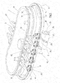
- the figure 1 and 2 shows a perspective view and of an embodiment of a transfer apparatus according the invention.
- the transfer apparatus 1 is configured to transfer single items 100.
- the items 100 are positioned on a first surface 101 formed by a rotary table 104.
- the rotary table 104 rotates around a table axis 107 as indicated by arrow 105.
- the transfer apparatus 1 is configured to transfer the items 100 to a second surface 102 located at a distance from the first surface 101.
- the second surface 102 is formed by an endless belt 103 transporting the received items 100 in the direction indicated by arrow 106.
- the transfer apparatus 1 comprises a rail 3 forming an endless track 4 along which the item 100 is transferred.
- the endless track 4 encloses an area 11.
- the endless track 4 comprises an inwards curved section 5 positioned adjacent to the rotary table 104.
- the rail 3 is constructed and arranged so the grippers 10 follow the rotary table 104.
- the part of the endless track 4 extending along the endless belt 103 follows a straight line.
- the second surface 102 also may be formed by a second rotary table is stead of the endless belt 103.
- the transfer apparatus 1 would require a second inwards curved section, as shown in fig. 3 .
- the shape of an inwards curved section 5 of the transfer apparatus 1 corresponds to the circular dimensions of the rotary table 104 used.
- the transfer apparatus 1 further comprises a first transporter 41 and a second transporter 42 which are movable along the rail 3 and a driver 7 (see fig. 5 ) for driving the transporters 41, 42 along the rail 3.
- the transporters 41, 42 are interconnected such that both transporters 41, 42 can be driven by one driver 7. For providing a clear view on the construction of the transfer apparatus 1, said interconnection is left out.
- the interconnection may by formed by additional carriers 8 coupled to each other and to the transporters 41, 42 by additional couplers 9.
- first and second transporter 41, 42 are integrated and form an endless chain of coupled carriers 8.
- Said endless transporter 41, 42 extends along the entire rail 3. All or part of the couplers 9 may be provided with a gripper 10.
- the first transporter 41 comprises four carriers 8 engaging the rail 3 and located at a distance from each other.
- the second transporter 42 comprises five of such carriers 8.
- neighbouring carriers 8 are coupled to each other by a coupler 9 carrying a gripper 10 for gripping one of the items 100.
- each gripper 10 comprises a gripper arm 18 which directs to the centre point 47 when passing the inwards curved section 5. Said centre point 47 coincides with the table axis 107.
- the rotary table 104 comprises first item regions 108 positioned along the circumference of the rotary table 104. Each item 100 located on the first surface 101 is positioned in a different first item region 108. When passing the first surface 101, the speed of the grippers 10 equals that of the first surface 101 and the gripper arms 18 are located above the first item regions 108. Each gripper arms 18 picks up an item 100 when passing the first surface 101.
- the transfer apparatus 1 is configured such that each gripper 10 picks up an item 100 when passing the same location 48 along the track 4. This means that there is only one grabbing location 48 along the track 4 where the grippers 10 pick up an item 100 of the first surface 101.
- the transfer apparatus 1 may also be provided with further grabbing locations 48 along the same or further surfaces.
- the grippers 10 holding the items 100 are moved along the track 4 towards the second surface 102.
- the second surface 102 is provided with second item regions 109.
- the speed of the grippers 10 equals that of the second surface 102.
- the grippers 10 place the item 100 in a corresponding second item region 109.
- the transfer apparatus 1 is configured such that each gripper 10 places down a held item 100 when passing the same location 49 along the track 4. This means that there is only one releasing location 49 along the track 4 where the grippers 10 place down an item 100.
- the transfer apparatus 1 may also be provided with further releasing locations 49 along the same or further surfaces.
- the transfer apparatus 1 comprises a tracking and tracing system of the individual items 100.
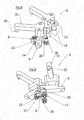
- FIG. 3 and 4 show a perspective view and top view of a second embodiment of a transfer apparatus according the invention, respectively.
- the endless track 4 comprises two inwards curved sections 5.
- the transfer apparatus 1 comprises an endless transporter 41.
- the part of the endless transporter 41 shown comprises ten carriers 8. Neighbouring carriers 8 are connected by a coupler 9.
- the couplers 9 are configured to carry a gripper 10. Only one gripper 10 is shown, but it will be clear the transporter 41 may be carrying additional grippers 10.
- the rail 3 comprises a first face 12 and a second face 13.
- Each carrier 8 comprises a first engage member 14 and a second engage member 15 engaging the first face 12 and a third engage member 16 engaging the second face 13.
- the engage members 14, 15, 16 of each carrier 8 are positioned relative to each other such that said engage members 14, 15, 16 form a triangle 35, more specifically an isosceles triangle.
- the base 38 of the triangle 35 extends between the first and second engage members 14 and 15.
- Each engage member 14, 15, 16 is formed by a roller 36 rotatable about a roller axis 36. As indicated in fig. 4 , each of the three roller axes 36 is positioned at a different vertex of the triangle 35.
- Each carrier 8 comprises a carrier body 20 which is connected to the three engage members 14, 15, 16 and has a triangle-like form.
- the first and second engage members 14, 15 are located outside the area 11 enclosed by the endless track 4 and the third engage member 16 is located inside said area 11.
- the form of the triangle-like carrier body 20 corresponds to the triangle 35 formed by the three engage members 14, 15, 16 and both triangles are oriented the same way.
- connection 39 of the coupler 9 to neighbouring carriers 8 comprises a coupler axis 21 about which the coupler 9 is pivotable relative to the carrier 8 comprising said connection 39.
- the carriers 8 are configured to rotate about a carrier axis 22 when being moved along curved sections 5 of the rail 3.
- the carrier axis 22 coincides with the coupler axis 21.
- Neighbouring couplers 9 are connected to the same carrier 8 and share the same coupler axis 21. As shown in fig. 4 , the gripper 10 is located in the middle between the two coupler axes 21 of neighbouring carriers 8.
- the gripper 10 comprises a gripping member 55 for grabbing the item.
- the gripping member 55 comprises two gripping parts for grabbing the item between said gripping parts.
- the gripper 10 comprises a pivot axis 56 about which the gripper 10 is pivotable for grabbing and releasing the item 100.
- FIG. 5 shows a perspective view of the driver of the transfer apparatus of fig. 1 .
- Each of the transporters 41, 42 comprise several drive protrusions 23.
- the drive protrusions 23 are connected to the carriers 8. More specifically, each carrier 8 comprises a drive protrusion 23. It is also possible that only a part of the carriers 8 are provided with a drive protrusion 23.
- the driver 7 comprises a screw-like surface 24 winded around a screw axis 25 and configured to move the transporters 41, 42 along the rail by engaging and pushing the drive protrusions 23 when the screw-like surface 24 is rotated around the screw axis 25. Said rotation of the screw-like surface 24 is indicated by arrow 45. The movement of the second transporter 42 is indicated by arrow 46.
- the driver 7 comprises a cylindrical body 26 comprising a cylinder housing 27 and being rotatable around the longitudinal axis 28 thereof.
- the screw-like surface 24 is formed by a groove 29 provided in the cylinder housing 27. Said groove 29 has a screw-like form winded around said longitudinal axis 28.
- the rail 3 comprises a rail longitudinal axis and the screw axis 25 of the screw-like surface 24 extends substantially parallel to said rail longitudinal axis.
- the longitudinal axis 28 of the cylindrical body 26 extends substantially parallel to said rail longitudinal axis.
- the driver 7 may comprise several screw-like surfaces 24 positioned along the track 4 and at a distance from each other. This ensures that the transporters 41, 42 are subjected to lower stress and strain.
- the pitch of the screw-like surface 24 is constant.
- the driver 7 is configured to rotate the screw-like surface 24 in opposite directions around the screw axis 25. As a result of this, the driver 7 is able to move the transporters 41, 42 in opposite directions.
- the drive protrusions 23 of the transporters 41, 42 are directed downwards. As a result of this, the screw-like surface 24 is located under the transporters 41, 42.
- a gripper steering 50 is provided to steer the grippers 10.
- the gripper steering 50 comprises a first profile 51 and a second profile 52 extending along the rail 3.
- the profiles may be provided in a plastic material or a metal material.
- the profiles 51, 52 may follow the shape of the rail 3.
- the grippers 10 are configured to be in contact and to follow the profiles 51, 52.
- the grippers 10 comprise first and second steering members 53, 54 which are in contact and follow the profiles 51, 52.
- the shape of the profiles 51, 52 move the steering members 51, 52 for steering the grippers 10. This way, the controller profiles 51, 52 ensure that the grippers 10 grab an item 100 at the grabbing location 48 and release the item 10 at the releasing location 49.
- the behaviour of the grippers 10 is adjustable by adjusting the shape of the profiles 51, 52.
- the profiles 51, 52 are located in the area 11 enclosed by the endless track 4.
- the transfer apparatus may be divided in two parts.
- the first part being the part comprising the profiles and the second part the rail and carriers.
- the transfer apparatus may be provided with an actuator to move the first part as a whole up with respect to the second part. All grippers may than release there items. The latter can be advantageously in case of emergency.
- Figure 6 shows a further perspective view of the transfer apparatus of fig. 5 .
- the first transporter 41 is located in the inwards curved section 5.
- the transporters 41, 42 are configured such that the grippers 10 are directed towards a centre point 47 when positioned in said inwards curved section 5. As shown in fig. 1 , in use said centre point 47 coincides with the table axis 107 of the rotary table 104.
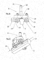
- Figure 7 shows a perspective view of the driver of the transfer apparatus of fig. 3 , wherein only part of the endless transporter 41 is shown.
- the drive protrusions 23 are directed outwards.
- the screw-like surface 24 is located at the side of the rail 3.
- the rail 3 comprises a rail longitudinal axis and the screw axis 25 of the screw-like surface 24 extends substantially parallel to said rail longitudinal axis.
- the longitudinal axis 28 of the cylindrical body 26 extends substantially parallel to said rail longitudinal axis.
- Each gripper 10 comprises a first protrusion 53 and a second protrusion 54.
- the protrusions may cooperate to open the gripper or to change the position of the gripper 10.
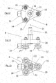
- Figure 10 shows a perspective view of the carrier of the transfer apparatus of fig. 3 .
- the figures 11-13 show a side view, a top view and a bottom view of the carrier of fig. 10 , respectively.
- the triangle base 38 of the isosceles triangle 35 is formed by the first and second engage members 14, 15.
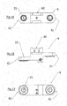
- Figure 14 shows a perspective view of the coupler of the transfer apparatus of fig. 3 .
- the coupler 9 comprises a first coupling end 61 and a second coupling end 62, each to be coupled to a different one of two neighbouring carriers 8 such that the coupler 9 is pivotable relative to said carrier and about coupler axis 21.
- a gripper receiver 60 is provided for receiving a gripper 10.
- the figure 15-17 shows a side view, top view and bottom view of the coupler of fig. 14 , respectively.
- Figure 18 and 19 show a side view and a perspective view of the carrier of fig. 10 engaging the rail, respectively.
- the rail 3 comprises a rail longitudinal axis 30 and the three engage members 14, 15, 16 engage the rail 3 such that rotation of the carrier 8 around the rail longitudinal axis 30 is prevented. This provides stability which is specifically useful when a gripper 10 grabs or releases an item 100.
- the invention further relates to a transfer apparatus, and method as defined in any of the following clauses.
Landscapes
- Engineering & Computer Science (AREA)
- Mechanical Engineering (AREA)
- Specific Conveyance Elements (AREA)
- Platform Screen Doors And Railroad Systems (AREA)
- Transmission Devices (AREA)
- Machines For Laying And Maintaining Railways (AREA)
- Supplying Of Containers To The Packaging Station (AREA)
- Auxiliary Devices For And Details Of Packaging Control (AREA)
- Control And Other Processes For Unpacking Of Materials (AREA)
Priority Applications (3)
| Application Number | Priority Date | Filing Date | Title |
|---|---|---|---|
| PL10763062T PL2483181T3 (pl) | 2009-09-29 | 2010-09-29 | Urządzenie przenośnikowe do przenoszenia przedmiotu |
| EP14168453.0A EP2784008B1 (en) | 2009-09-29 | 2010-09-29 | Transfer apparatus for transferring an item |
| PL14168453T PL2784008T3 (pl) | 2009-09-29 | 2010-09-29 | Urządzenie przenośnikowe do przenoszenia przedmiotu |
Applications Claiming Priority (3)
| Application Number | Priority Date | Filing Date | Title |
|---|---|---|---|
| NL2003570A NL2003570C2 (en) | 2009-09-29 | 2009-09-29 | Transfer apparatus for transferring an item. |
| NL2004278A NL2004278C2 (en) | 2010-02-22 | 2010-02-22 | Transfer apparatus for transferring an item. |
| PCT/NL2010/050637 WO2011040810A1 (en) | 2009-09-29 | 2010-09-29 | Transfer apparatus for transferring an item. |
Related Child Applications (1)
| Application Number | Title | Priority Date | Filing Date |
|---|---|---|---|
| EP14168453.0A Division EP2784008B1 (en) | 2009-09-29 | 2010-09-29 | Transfer apparatus for transferring an item |
Publications (2)
| Publication Number | Publication Date |
|---|---|
| EP2483181A1 EP2483181A1 (en) | 2012-08-08 |
| EP2483181B1 true EP2483181B1 (en) | 2014-05-28 |
Family
ID=42989273
Family Applications (2)
| Application Number | Title | Priority Date | Filing Date |
|---|---|---|---|
| EP10763062.6A Active EP2483181B1 (en) | 2009-09-29 | 2010-09-29 | Transfer apparatus for transferring an item. |
| EP14168453.0A Active EP2784008B1 (en) | 2009-09-29 | 2010-09-29 | Transfer apparatus for transferring an item |
Family Applications After (1)
| Application Number | Title | Priority Date | Filing Date |
|---|---|---|---|
| EP14168453.0A Active EP2784008B1 (en) | 2009-09-29 | 2010-09-29 | Transfer apparatus for transferring an item |
Country Status (11)
| Country | Link |
|---|---|
| US (1) | US8776988B2 (da) |
| EP (2) | EP2483181B1 (da) |
| KR (1) | KR101570423B1 (da) |
| CN (1) | CN102574642B (da) |
| CA (1) | CA2775396C (da) |
| DK (1) | DK2483181T3 (da) |
| ES (2) | ES2496185T3 (da) |
| HR (1) | HRP20140689T1 (da) |
| PL (2) | PL2483181T3 (da) |
| PT (1) | PT2483181E (da) |
| WO (1) | WO2011040810A1 (da) |
Families Citing this family (9)
| Publication number | Priority date | Publication date | Assignee | Title |
|---|---|---|---|---|
| ITMI20111762A1 (it) * | 2011-09-30 | 2013-03-31 | Smi Spa | Forno per preforme applicabile a macchine soffiatrici o stirosoffiatrici |
| FR2981920B1 (fr) | 2011-10-26 | 2015-08-07 | Serac Group | Dispositif de transfert d'articles entre des machines a deplacement intermittent et a deplacement continu des articles et installation de conditionnement correspondante |
| CN104176441A (zh) * | 2013-05-28 | 2014-12-03 | 北京中电科电子装备有限公司 | 具有缺陷检测功能的工件传输装置 |
| CN104176431A (zh) * | 2013-05-28 | 2014-12-03 | 北京中电科电子装备有限公司 | 具有静电消除功能的工件传输装置 |
| CN103419963B (zh) * | 2013-08-29 | 2015-10-28 | 昆山倚天自动化有限公司 | 多物料供应及自动封边装置 |
| NL2012832B1 (en) * | 2014-05-16 | 2016-03-02 | Sluis Cigar Machinery Bv | Adjusting spaces between electronic cigarette tubes. |
| NL2012834B1 (en) * | 2014-05-16 | 2016-03-02 | Sluis Cigar Machinery Bv | System for performing a processing step on cigarette parts of an electronic cigarette. |
| EP2987764B1 (de) * | 2014-08-20 | 2018-09-19 | Krones AG | Überschwappvermeidung bei Formfüllmaschinen |
| IT202100009941A1 (it) * | 2021-04-20 | 2022-10-20 | Pe Labellers Spa | Macchina a giostra per il trattamento di contenitori. |
Family Cites Families (21)
| Publication number | Priority date | Publication date | Assignee | Title |
|---|---|---|---|---|
| US3330400A (en) | 1966-03-08 | 1967-07-11 | Miehle Goss Dexter Inc | Mechanism for transferring cylindrical articles |
| US3567043A (en) * | 1968-08-05 | 1971-03-02 | Sun Chemical Corp | Transfer assembly for use with container printing machines |
| DE6801212U (de) * | 1968-10-08 | 1969-06-26 | Brueckner Maschb Gernot Brueck | Spannkluppenkette |
| GB1263669A (en) * | 1970-04-10 | 1972-02-16 | Gough & Co Ltd | Improvements in guided chain type conveyors |
| DE2109709A1 (de) | 1971-03-02 | 1972-09-14 | Haensel Otto Gmbh | Verfahren und Vorrichtung zum Übergeben von Werk stucken von einem Forderer an einen folgenden, insbeson dere von Packmaterialzuschmtten bei Packmaschinen |
| US3944058A (en) * | 1973-04-19 | 1976-03-16 | Indian Head Inc. | Bottle conveyor system including adjustable height continuous belt conveyor and positive lock spray shielded rotatable bottle carrier |
| US3985223A (en) * | 1975-09-22 | 1976-10-12 | Fmc Corporation | Universal gripper assembly for frozen confections |
| US4283973A (en) * | 1979-11-15 | 1981-08-18 | Paper Converting Machine Company | Method and apparatus for handling articles |
| US4638906A (en) | 1985-11-19 | 1987-01-27 | Harris Graphics Corporation | Conveyor assembly |
| NL9001682A (nl) | 1990-07-24 | 1992-02-17 | Staalkat Bv | Drager voor voorwerpen zoals eieren en transportinrichting voorzien van een dergelijke drager. |
| EP0633212B1 (de) * | 1993-07-07 | 1997-03-26 | Ferag AG | Endlos umlaufende Stückgut-Transportvorrichtung mit individuellen Transportorganen |
| ITBO20030352A1 (it) | 2003-06-10 | 2003-09-08 | Cosmopack Srl | Sistema per traslare et orientare orizzontalmente degli oggetti, in particolare contenitori, con moto continuo |
| US7055676B2 (en) * | 2003-11-13 | 2006-06-06 | Hartness International, Inc. | Conveyor with movable gripper and related conveyor link |
| US7264113B2 (en) | 2003-11-13 | 2007-09-04 | Hartness International, Inc. | Pivotable conveyor and link |
| US7207434B2 (en) | 2003-11-13 | 2007-04-24 | Hartness International, Inc. | Conveyor with center-actuatable gripper, and related conveyor link |
| DE502004004281D1 (de) * | 2004-01-21 | 2007-08-23 | Mueller Martini Holding Ag | Transportorgan mit einer Gliederkette und Klammern |
| EP1711420B1 (de) * | 2004-02-02 | 2016-04-06 | Krones AG | Vorrichtung zum dynamischen speichern von gegenständen |
| ITTO20050832A1 (it) * | 2005-11-24 | 2007-05-25 | Opm S P A | Convogliatore ad anello per il trasferimento di prodotti, in particolare prodotti alimentari |
| JP5282239B2 (ja) * | 2007-09-20 | 2013-09-04 | 東洋製罐株式会社 | 円筒体搬送用グリッパ装置 |
| DE102007048861A1 (de) | 2007-10-11 | 2009-04-16 | Robert Bosch Gmbh | Reinigungseinrichtung mit verbessertem Transportsystem |
| AU2010241266B2 (en) * | 2009-11-18 | 2015-03-12 | Muller Martini Holding Ag | Transport device for conveying printed products |
-
2010
- 2010-09-29 WO PCT/NL2010/050637 patent/WO2011040810A1/en not_active Ceased
- 2010-09-29 ES ES10763062.6T patent/ES2496185T3/es active Active
- 2010-09-29 EP EP10763062.6A patent/EP2483181B1/en active Active
- 2010-09-29 PL PL10763062T patent/PL2483181T3/pl unknown
- 2010-09-29 US US13/498,420 patent/US8776988B2/en active Active
- 2010-09-29 HR HRP20140689AT patent/HRP20140689T1/hr unknown
- 2010-09-29 EP EP14168453.0A patent/EP2784008B1/en active Active
- 2010-09-29 PT PT107630626T patent/PT2483181E/pt unknown
- 2010-09-29 PL PL14168453T patent/PL2784008T3/pl unknown
- 2010-09-29 KR KR1020127010939A patent/KR101570423B1/ko not_active Expired - Fee Related
- 2010-09-29 CN CN201080043360.XA patent/CN102574642B/zh not_active Expired - Fee Related
- 2010-09-29 ES ES14168453.0T patent/ES2562930T3/es active Active
- 2010-09-29 CA CA2775396A patent/CA2775396C/en active Active
- 2010-09-29 DK DK10763062.6T patent/DK2483181T3/da active
Also Published As
| Publication number | Publication date |
|---|---|
| EP2483181A1 (en) | 2012-08-08 |
| CN102574642B (zh) | 2014-08-27 |
| EP2784008A1 (en) | 2014-10-01 |
| PL2784008T3 (pl) | 2016-05-31 |
| PL2483181T3 (pl) | 2014-11-28 |
| HRP20140689T1 (hr) | 2014-09-26 |
| CA2775396C (en) | 2016-02-02 |
| CA2775396A1 (en) | 2011-04-07 |
| ES2562930T3 (es) | 2016-03-09 |
| EP2784008B1 (en) | 2015-11-18 |
| CN102574642A (zh) | 2012-07-11 |
| KR101570423B1 (ko) | 2015-11-19 |
| WO2011040810A1 (en) | 2011-04-07 |
| DK2483181T3 (da) | 2014-08-25 |
| KR20120097494A (ko) | 2012-09-04 |
| PT2483181E (pt) | 2014-07-29 |
| US8776988B2 (en) | 2014-07-15 |
| ES2496185T3 (es) | 2014-09-18 |
| US20120228087A1 (en) | 2012-09-13 |
Similar Documents
| Publication | Publication Date | Title |
|---|---|---|
| EP2483181B1 (en) | Transfer apparatus for transferring an item. | |
| ES2901162T3 (es) | Procedimiento y dispositivo para la manipulación de mercancías en piezas trasladadas una detrás de otra en al menos una fila | |
| EP1246767B1 (en) | Apparatus for repositioning products while maintaining forward conveying speed | |
| US8342508B2 (en) | System for transferring objects | |
| WO2012088437A2 (en) | Adjustable conveyor extensions | |
| ITRM20090121A1 (it) | Testa di presa in particolare per impianto di confezionamento e relativo impianto di confezionamento | |
| EP2542490B1 (en) | Carton stacking apparatus and methods | |
| AU2002339289B2 (en) | Installation for assembling tube components | |
| CN1847094A (zh) | 拾取和打开适用于包装产品的箱子的装置 | |
| ES2863323T3 (es) | Procedimiento y dispositivo para el manejo de mercancías por piezas movidas sucesivamente al menos en una serie | |
| NL2003570C2 (en) | Transfer apparatus for transferring an item. | |
| WO2014006707A1 (ja) | 搬送コンベヤ及び搬送設備(transport conveyer and transport facility) | |
| EP2668124B1 (en) | Annular conveyor | |
| CN211569360U (zh) | 一种轮毂中转输送系统 | |
| NL2004278C2 (en) | Transfer apparatus for transferring an item. | |
| EP1048594B1 (en) | Conveyor device provided with a turning station | |
| ES2879449T3 (es) | Aparato para transportar un carrito | |
| JPS6233167B2 (da) | ||
| EP4291364B1 (en) | A movement system of a pick and place robot | |
| JP2005119720A (ja) | キャップ巻締装置 | |
| CN112758568A (zh) | 一种新型机场应急助航灯光车用自动化布设与撤收分系统 | |
| CN117446399A (zh) | 一种货物堆垛平移转运装置 | |
| JP2000318710A (ja) | ケーキの整列装置 | |
| RU97102137A (ru) | Устройство для разделения и для передачи штучного груза, в частности почтового груза | |
| ITUD950075A1 (it) | Gruppo impaccatore amagnetico per materiali laminati e/o profilati in genere |
Legal Events
| Date | Code | Title | Description |
|---|---|---|---|
| PUAI | Public reference made under article 153(3) epc to a published international application that has entered the european phase |
Free format text: ORIGINAL CODE: 0009012 |
|
| 17P | Request for examination filed |
Effective date: 20120418 |
|
| AK | Designated contracting states |
Kind code of ref document: A1 Designated state(s): AL AT BE BG CH CY CZ DE DK EE ES FI FR GB GR HR HU IE IS IT LI LT LU LV MC MK MT NL NO PL PT RO SE SI SK SM TR |
|
| RAP1 | Party data changed (applicant data changed or rights of an application transferred) |
Owner name: SLUIS CIGAR MACHINERY B.V. |
|
| DAX | Request for extension of the european patent (deleted) | ||
| 17Q | First examination report despatched |
Effective date: 20130208 |
|
| GRAP | Despatch of communication of intention to grant a patent |
Free format text: ORIGINAL CODE: EPIDOSNIGR1 |
|
| INTG | Intention to grant announced |
Effective date: 20131206 |
|
| GRAS | Grant fee paid |
Free format text: ORIGINAL CODE: EPIDOSNIGR3 |
|
| GRAA | (expected) grant |
Free format text: ORIGINAL CODE: 0009210 |
|
| AK | Designated contracting states |
Kind code of ref document: B1 Designated state(s): AL AT BE BG CH CY CZ DE DK EE ES FI FR GB GR HR HU IE IS IT LI LT LU LV MC MK MT NL NO PL PT RO SE SI SK SM TR |
|
| REG | Reference to a national code |
Ref country code: GB Ref legal event code: FG4D |
|
| REG | Reference to a national code |
Ref country code: CH Ref legal event code: EP |
|
| REG | Reference to a national code |
Ref country code: AT Ref legal event code: REF Ref document number: 670278 Country of ref document: AT Kind code of ref document: T Effective date: 20140615 |
|
| REG | Reference to a national code |
Ref country code: IE Ref legal event code: FG4D |
|
| REG | Reference to a national code |
Ref country code: DE Ref legal event code: R096 Ref document number: 602010016364 Country of ref document: DE Effective date: 20140710 |
|
| REG | Reference to a national code |
Ref country code: HR Ref legal event code: TUEP Ref document number: P20140689 Country of ref document: HR |
|
| REG | Reference to a national code |
Ref country code: PT Ref legal event code: SC4A Free format text: AVAILABILITY OF NATIONAL TRANSLATION Effective date: 20140722 |
|
| REG | Reference to a national code |
Ref country code: CH Ref legal event code: NV Representative=s name: FIAMMENGHI-FIAMMENGHI, CH |
|
| REG | Reference to a national code |
Ref country code: DK Ref legal event code: T3 Effective date: 20140822 |
|
| REG | Reference to a national code |
Ref country code: SE Ref legal event code: TRGR |
|
| REG | Reference to a national code |
Ref country code: ES Ref legal event code: FG2A Ref document number: 2496185 Country of ref document: ES Kind code of ref document: T3 Effective date: 20140918 |
|
| REG | Reference to a national code |
Ref country code: HR Ref legal event code: T1PR Ref document number: P20140689 Country of ref document: HR |
|
| REG | Reference to a national code |
Ref country code: NL Ref legal event code: T3 |
|
| REG | Reference to a national code |
Ref country code: GR Ref legal event code: EP Ref document number: 20140401539 Country of ref document: GR Effective date: 20140930 |
|
| REG | Reference to a national code |
Ref country code: LT Ref legal event code: MG4D |
|
| PG25 | Lapsed in a contracting state [announced via postgrant information from national office to epo] |
Ref country code: LT Free format text: LAPSE BECAUSE OF FAILURE TO SUBMIT A TRANSLATION OF THE DESCRIPTION OR TO PAY THE FEE WITHIN THE PRESCRIBED TIME-LIMIT Effective date: 20140528 Ref country code: NO Free format text: LAPSE BECAUSE OF FAILURE TO SUBMIT A TRANSLATION OF THE DESCRIPTION OR TO PAY THE FEE WITHIN THE PRESCRIBED TIME-LIMIT Effective date: 20140828 Ref country code: FI Free format text: LAPSE BECAUSE OF FAILURE TO SUBMIT A TRANSLATION OF THE DESCRIPTION OR TO PAY THE FEE WITHIN THE PRESCRIBED TIME-LIMIT Effective date: 20140528 Ref country code: IS Free format text: LAPSE BECAUSE OF FAILURE TO SUBMIT A TRANSLATION OF THE DESCRIPTION OR TO PAY THE FEE WITHIN THE PRESCRIBED TIME-LIMIT Effective date: 20140928 Ref country code: CY Free format text: LAPSE BECAUSE OF FAILURE TO SUBMIT A TRANSLATION OF THE DESCRIPTION OR TO PAY THE FEE WITHIN THE PRESCRIBED TIME-LIMIT Effective date: 20140528 |
|
| PG25 | Lapsed in a contracting state [announced via postgrant information from national office to epo] |
Ref country code: LV Free format text: LAPSE BECAUSE OF FAILURE TO SUBMIT A TRANSLATION OF THE DESCRIPTION OR TO PAY THE FEE WITHIN THE PRESCRIBED TIME-LIMIT Effective date: 20140528 |
|
| REG | Reference to a national code |
Ref country code: PL Ref legal event code: T3 Ref country code: HU Ref legal event code: AG4A Ref document number: E020909 Country of ref document: HU |
|
| PG25 | Lapsed in a contracting state [announced via postgrant information from national office to epo] |
Ref country code: RO Free format text: LAPSE BECAUSE OF FAILURE TO SUBMIT A TRANSLATION OF THE DESCRIPTION OR TO PAY THE FEE WITHIN THE PRESCRIBED TIME-LIMIT Effective date: 20140528 Ref country code: BE Free format text: LAPSE BECAUSE OF FAILURE TO SUBMIT A TRANSLATION OF THE DESCRIPTION OR TO PAY THE FEE WITHIN THE PRESCRIBED TIME-LIMIT Effective date: 20140528 Ref country code: SK Free format text: LAPSE BECAUSE OF FAILURE TO SUBMIT A TRANSLATION OF THE DESCRIPTION OR TO PAY THE FEE WITHIN THE PRESCRIBED TIME-LIMIT Effective date: 20140528 Ref country code: EE Free format text: LAPSE BECAUSE OF FAILURE TO SUBMIT A TRANSLATION OF THE DESCRIPTION OR TO PAY THE FEE WITHIN THE PRESCRIBED TIME-LIMIT Effective date: 20140528 |
|
| REG | Reference to a national code |
Ref country code: DE Ref legal event code: R097 Ref document number: 602010016364 Country of ref document: DE |
|
| PLBE | No opposition filed within time limit |
Free format text: ORIGINAL CODE: 0009261 |
|
| STAA | Information on the status of an ep patent application or granted ep patent |
Free format text: STATUS: NO OPPOSITION FILED WITHIN TIME LIMIT |
|
| PG25 | Lapsed in a contracting state [announced via postgrant information from national office to epo] |
Ref country code: MC Free format text: LAPSE BECAUSE OF FAILURE TO SUBMIT A TRANSLATION OF THE DESCRIPTION OR TO PAY THE FEE WITHIN THE PRESCRIBED TIME-LIMIT Effective date: 20140528 |
|
| 26N | No opposition filed |
Effective date: 20150303 |
|
| REG | Reference to a national code |
Ref country code: DE Ref legal event code: R097 Ref document number: 602010016364 Country of ref document: DE Effective date: 20150303 |
|
| PG25 | Lapsed in a contracting state [announced via postgrant information from national office to epo] |
Ref country code: SI Free format text: LAPSE BECAUSE OF FAILURE TO SUBMIT A TRANSLATION OF THE DESCRIPTION OR TO PAY THE FEE WITHIN THE PRESCRIBED TIME-LIMIT Effective date: 20140528 |
|
| PG25 | Lapsed in a contracting state [announced via postgrant information from national office to epo] |
Ref country code: SM Free format text: LAPSE BECAUSE OF FAILURE TO SUBMIT A TRANSLATION OF THE DESCRIPTION OR TO PAY THE FEE WITHIN THE PRESCRIBED TIME-LIMIT Effective date: 20140528 |
|
| PG25 | Lapsed in a contracting state [announced via postgrant information from national office to epo] |
Ref country code: MT Free format text: LAPSE BECAUSE OF FAILURE TO SUBMIT A TRANSLATION OF THE DESCRIPTION OR TO PAY THE FEE WITHIN THE PRESCRIBED TIME-LIMIT Effective date: 20140528 Ref country code: BG Free format text: LAPSE BECAUSE OF FAILURE TO SUBMIT A TRANSLATION OF THE DESCRIPTION OR TO PAY THE FEE WITHIN THE PRESCRIBED TIME-LIMIT Effective date: 20140528 |
|
| PG25 | Lapsed in a contracting state [announced via postgrant information from national office to epo] |
Ref country code: TR Free format text: LAPSE BECAUSE OF FAILURE TO SUBMIT A TRANSLATION OF THE DESCRIPTION OR TO PAY THE FEE WITHIN THE PRESCRIBED TIME-LIMIT Effective date: 20140528 |
|
| REG | Reference to a national code |
Ref country code: FR Ref legal event code: PLFP Year of fee payment: 7 |
|
| REG | Reference to a national code |
Ref country code: FR Ref legal event code: PLFP Year of fee payment: 8 |
|
| PG25 | Lapsed in a contracting state [announced via postgrant information from national office to epo] |
Ref country code: MK Free format text: LAPSE BECAUSE OF FAILURE TO SUBMIT A TRANSLATION OF THE DESCRIPTION OR TO PAY THE FEE WITHIN THE PRESCRIBED TIME-LIMIT Effective date: 20140528 |
|
| REG | Reference to a national code |
Ref country code: FR Ref legal event code: PLFP Year of fee payment: 9 |
|
| PG25 | Lapsed in a contracting state [announced via postgrant information from national office to epo] |
Ref country code: AL Free format text: LAPSE BECAUSE OF FAILURE TO SUBMIT A TRANSLATION OF THE DESCRIPTION OR TO PAY THE FEE WITHIN THE PRESCRIBED TIME-LIMIT Effective date: 20140528 |
|
| REG | Reference to a national code |
Ref country code: HR Ref legal event code: ODRP Ref document number: P20140689 Country of ref document: HR Payment date: 20190904 Year of fee payment: 10 |
|
| REG | Reference to a national code |
Ref country code: HR Ref legal event code: ODRP Ref document number: P20140689 Country of ref document: HR Payment date: 20200923 Year of fee payment: 11 |
|
| REG | Reference to a national code |
Ref country code: HR Ref legal event code: ODRP Ref document number: P20140689 Country of ref document: HR Payment date: 20210924 Year of fee payment: 12 |
|
| REG | Reference to a national code |
Ref country code: HR Ref legal event code: ODRP Ref document number: P20140689 Country of ref document: HR Payment date: 20220921 Year of fee payment: 13 |
|
| PGFP | Annual fee paid to national office [announced via postgrant information from national office to epo] |
Ref country code: SE Payment date: 20220923 Year of fee payment: 13 Ref country code: PT Payment date: 20220926 Year of fee payment: 13 Ref country code: NL Payment date: 20220926 Year of fee payment: 13 Ref country code: LU Payment date: 20220923 Year of fee payment: 13 Ref country code: IE Payment date: 20220919 Year of fee payment: 13 Ref country code: HR Payment date: 20220921 Year of fee payment: 13 Ref country code: GB Payment date: 20220923 Year of fee payment: 13 Ref country code: DK Payment date: 20220922 Year of fee payment: 13 Ref country code: DE Payment date: 20220922 Year of fee payment: 13 Ref country code: CZ Payment date: 20220919 Year of fee payment: 13 Ref country code: AT Payment date: 20220922 Year of fee payment: 13 |
|
| PGFP | Annual fee paid to national office [announced via postgrant information from national office to epo] |
Ref country code: PL Payment date: 20220920 Year of fee payment: 13 Ref country code: HU Payment date: 20220919 Year of fee payment: 13 Ref country code: GR Payment date: 20220920 Year of fee payment: 13 Ref country code: FR Payment date: 20220923 Year of fee payment: 13 Ref country code: BE Payment date: 20220923 Year of fee payment: 13 |
|
| PGFP | Annual fee paid to national office [announced via postgrant information from national office to epo] |
Ref country code: IT Payment date: 20220926 Year of fee payment: 13 Ref country code: ES Payment date: 20221221 Year of fee payment: 13 |
|
| PGFP | Annual fee paid to national office [announced via postgrant information from national office to epo] |
Ref country code: CH Payment date: 20220927 Year of fee payment: 13 |
|
| P01 | Opt-out of the competence of the unified patent court (upc) registered |
Effective date: 20230522 |
|
| REG | Reference to a national code |
Ref country code: DE Ref legal event code: R119 Ref document number: 602010016364 Country of ref document: DE |
|
| REG | Reference to a national code |
Ref country code: HR Ref legal event code: PBON Ref document number: P20140689 Country of ref document: HR Effective date: 20230929 |
|
| REG | Reference to a national code |
Ref country code: DK Ref legal event code: EBP Effective date: 20230930 |
|
| PG25 | Lapsed in a contracting state [announced via postgrant information from national office to epo] |
Ref country code: CZ Free format text: LAPSE BECAUSE OF NON-PAYMENT OF DUE FEES Effective date: 20230929 |
|
| REG | Reference to a national code |
Ref country code: CH Ref legal event code: PL Ref country code: SE Ref legal event code: EUG |
|
| REG | Reference to a national code |
Ref country code: NL Ref legal event code: MM Effective date: 20231001 |
|
| REG | Reference to a national code |
Ref country code: AT Ref legal event code: MM01 Ref document number: 670278 Country of ref document: AT Kind code of ref document: T Effective date: 20230929 |
|
| PG25 | Lapsed in a contracting state [announced via postgrant information from national office to epo] |
Ref country code: LU Free format text: LAPSE BECAUSE OF NON-PAYMENT OF DUE FEES Effective date: 20230929 |
|
| REG | Reference to a national code |
Ref country code: BE Ref legal event code: MM Effective date: 20230930 |
|
| GBPC | Gb: european patent ceased through non-payment of renewal fee |
Effective date: 20230929 |
|
| PG25 | Lapsed in a contracting state [announced via postgrant information from national office to epo] |
Ref country code: LU Free format text: LAPSE BECAUSE OF NON-PAYMENT OF DUE FEES Effective date: 20230929 |
|
| PG25 | Lapsed in a contracting state [announced via postgrant information from national office to epo] |
Ref country code: NL Free format text: LAPSE BECAUSE OF NON-PAYMENT OF DUE FEES Effective date: 20231001 |
|
| PG25 | Lapsed in a contracting state [announced via postgrant information from national office to epo] |
Ref country code: NL Free format text: LAPSE BECAUSE OF NON-PAYMENT OF DUE FEES Effective date: 20231001 |
|
| REG | Reference to a national code |
Ref country code: IE Ref legal event code: MM4A |
|
| PG25 | Lapsed in a contracting state [announced via postgrant information from national office to epo] |
Ref country code: IE Free format text: LAPSE BECAUSE OF NON-PAYMENT OF DUE FEES Effective date: 20230929 |
|
| PG25 | Lapsed in a contracting state [announced via postgrant information from national office to epo] |
Ref country code: GB Free format text: LAPSE BECAUSE OF NON-PAYMENT OF DUE FEES Effective date: 20230929 |
|
| PG25 | Lapsed in a contracting state [announced via postgrant information from national office to epo] |
Ref country code: GR Free format text: LAPSE BECAUSE OF NON-PAYMENT OF DUE FEES Effective date: 20240408 |
|
| PG25 | Lapsed in a contracting state [announced via postgrant information from national office to epo] |
Ref country code: CH Free format text: LAPSE BECAUSE OF NON-PAYMENT OF DUE FEES Effective date: 20230930 Ref country code: HR Free format text: LAPSE BECAUSE OF NON-PAYMENT OF DUE FEES Effective date: 20230929 |
|
| PG25 | Lapsed in a contracting state [announced via postgrant information from national office to epo] |
Ref country code: AT Free format text: LAPSE BECAUSE OF NON-PAYMENT OF DUE FEES Effective date: 20230929 |
|
| PG25 | Lapsed in a contracting state [announced via postgrant information from national office to epo] |
Ref country code: IE Free format text: LAPSE BECAUSE OF NON-PAYMENT OF DUE FEES Effective date: 20230929 Ref country code: HR Free format text: LAPSE BECAUSE OF NON-PAYMENT OF DUE FEES Effective date: 20230929 Ref country code: GR Free format text: LAPSE BECAUSE OF NON-PAYMENT OF DUE FEES Effective date: 20240408 Ref country code: GB Free format text: LAPSE BECAUSE OF NON-PAYMENT OF DUE FEES Effective date: 20230929 Ref country code: FR Free format text: LAPSE BECAUSE OF NON-PAYMENT OF DUE FEES Effective date: 20230930 Ref country code: DE Free format text: LAPSE BECAUSE OF NON-PAYMENT OF DUE FEES Effective date: 20240403 Ref country code: CH Free format text: LAPSE BECAUSE OF NON-PAYMENT OF DUE FEES Effective date: 20230930 Ref country code: AT Free format text: LAPSE BECAUSE OF NON-PAYMENT OF DUE FEES Effective date: 20230929 |
|
| PG25 | Lapsed in a contracting state [announced via postgrant information from national office to epo] |
Ref country code: PT Free format text: LAPSE BECAUSE OF NON-PAYMENT OF DUE FEES Effective date: 20240401 |
|
| PG25 | Lapsed in a contracting state [announced via postgrant information from national office to epo] |
Ref country code: SE Free format text: LAPSE BECAUSE OF NON-PAYMENT OF DUE FEES Effective date: 20230930 Ref country code: PT Free format text: LAPSE BECAUSE OF NON-PAYMENT OF DUE FEES Effective date: 20240401 Ref country code: HU Free format text: LAPSE BECAUSE OF NON-PAYMENT OF DUE FEES Effective date: 20230930 Ref country code: BE Free format text: LAPSE BECAUSE OF NON-PAYMENT OF DUE FEES Effective date: 20230930 |
|
| PG25 | Lapsed in a contracting state [announced via postgrant information from national office to epo] |
Ref country code: DK Free format text: LAPSE BECAUSE OF NON-PAYMENT OF DUE FEES Effective date: 20230930 |
|
| PG25 | Lapsed in a contracting state [announced via postgrant information from national office to epo] |
Ref country code: PL Free format text: LAPSE BECAUSE OF NON-PAYMENT OF DUE FEES Effective date: 20230929 |
|
| PG25 | Lapsed in a contracting state [announced via postgrant information from national office to epo] |
Ref country code: PL Free format text: LAPSE BECAUSE OF NON-PAYMENT OF DUE FEES Effective date: 20230929 Ref country code: DK Free format text: LAPSE BECAUSE OF NON-PAYMENT OF DUE FEES Effective date: 20230930 |
|
| REG | Reference to a national code |
Ref country code: ES Ref legal event code: FD2A Effective date: 20241104 |
|
| PG25 | Lapsed in a contracting state [announced via postgrant information from national office to epo] |
Ref country code: IT Free format text: LAPSE BECAUSE OF NON-PAYMENT OF DUE FEES Effective date: 20230929 |
|
| PG25 | Lapsed in a contracting state [announced via postgrant information from national office to epo] |
Ref country code: IT Free format text: LAPSE BECAUSE OF NON-PAYMENT OF DUE FEES Effective date: 20230929 |
|
| PG25 | Lapsed in a contracting state [announced via postgrant information from national office to epo] |
Ref country code: ES Free format text: LAPSE BECAUSE OF NON-PAYMENT OF DUE FEES Effective date: 20230930 |
|
| PG25 | Lapsed in a contracting state [announced via postgrant information from national office to epo] |
Ref country code: ES Free format text: LAPSE BECAUSE OF NON-PAYMENT OF DUE FEES Effective date: 20230930 |