EP2482113B1 - Microscope d'opération doté d'un système OCT - Google Patents
Microscope d'opération doté d'un système OCT Download PDFInfo
- Publication number
- EP2482113B1 EP2482113B1 EP12165225.9A EP12165225A EP2482113B1 EP 2482113 B1 EP2482113 B1 EP 2482113B1 EP 12165225 A EP12165225 A EP 12165225A EP 2482113 B1 EP2482113 B1 EP 2482113B1
- Authority
- EP
- European Patent Office
- Prior art keywords
- oct
- scanning
- beam path
- surgical microscope
- ophthalmic surgical
- Prior art date
- Legal status (The legal status is an assumption and is not a legal conclusion. Google has not performed a legal analysis and makes no representation as to the accuracy of the status listed.)
- Active
Links
- 230000003287 optical effect Effects 0.000 claims description 31
- 238000002577 ophthalmoscopy Methods 0.000 claims description 13
- 230000008878 coupling Effects 0.000 claims description 2
- 238000010168 coupling process Methods 0.000 claims description 2
- 238000005859 coupling reaction Methods 0.000 claims description 2
- 230000001131 transforming effect Effects 0.000 claims 1
- 238000012014 optical coherence tomography Methods 0.000 description 190
- 230000005855 radiation Effects 0.000 description 23
- 239000000835 fiber Substances 0.000 description 8
- 238000011161 development Methods 0.000 description 7
- 239000013307 optical fiber Substances 0.000 description 6
- 230000000875 corresponding effect Effects 0.000 description 5
- 238000005286 illumination Methods 0.000 description 5
- 238000004458 analytical method Methods 0.000 description 4
- 230000000712 assembly Effects 0.000 description 2
- 238000000429 assembly Methods 0.000 description 2
- 238000005259 measurement Methods 0.000 description 2
- 230000003595 spectral effect Effects 0.000 description 2
- 208000003174 Brain Neoplasms Diseases 0.000 description 1
- 210000002159 anterior chamber Anatomy 0.000 description 1
- 210000005013 brain tissue Anatomy 0.000 description 1
- 230000001427 coherent effect Effects 0.000 description 1
- 238000002591 computed tomography Methods 0.000 description 1
- 238000010276 construction Methods 0.000 description 1
- 210000004087 cornea Anatomy 0.000 description 1
- 230000002596 correlated effect Effects 0.000 description 1
- 230000007423 decrease Effects 0.000 description 1
- 238000013461 design Methods 0.000 description 1
- 238000011156 evaluation Methods 0.000 description 1
- 238000003384 imaging method Methods 0.000 description 1
- 238000000034 method Methods 0.000 description 1
- 230000000926 neurological effect Effects 0.000 description 1
- 238000012634 optical imaging Methods 0.000 description 1
- 230000000007 visual effect Effects 0.000 description 1
Images


Classifications
-
- A—HUMAN NECESSITIES
- A61—MEDICAL OR VETERINARY SCIENCE; HYGIENE
- A61B—DIAGNOSIS; SURGERY; IDENTIFICATION
- A61B3/00—Apparatus for testing the eyes; Instruments for examining the eyes
- A61B3/10—Objective types, i.e. instruments for examining the eyes independent of the patients' perceptions or reactions
- A61B3/13—Ophthalmic microscopes
-
- A—HUMAN NECESSITIES
- A61—MEDICAL OR VETERINARY SCIENCE; HYGIENE
- A61B—DIAGNOSIS; SURGERY; IDENTIFICATION
- A61B3/00—Apparatus for testing the eyes; Instruments for examining the eyes
- A61B3/10—Objective types, i.e. instruments for examining the eyes independent of the patients' perceptions or reactions
- A61B3/102—Objective types, i.e. instruments for examining the eyes independent of the patients' perceptions or reactions for optical coherence tomography [OCT]
-
- G—PHYSICS
- G01—MEASURING; TESTING
- G01B—MEASURING LENGTH, THICKNESS OR SIMILAR LINEAR DIMENSIONS; MEASURING ANGLES; MEASURING AREAS; MEASURING IRREGULARITIES OF SURFACES OR CONTOURS
- G01B9/00—Measuring instruments characterised by the use of optical techniques
- G01B9/02—Interferometers
- G01B9/02001—Interferometers characterised by controlling or generating intrinsic radiation properties
- G01B9/02007—Two or more frequencies or sources used for interferometric measurement
-
- G—PHYSICS
- G01—MEASURING; TESTING
- G01B—MEASURING LENGTH, THICKNESS OR SIMILAR LINEAR DIMENSIONS; MEASURING ANGLES; MEASURING AREAS; MEASURING IRREGULARITIES OF SURFACES OR CONTOURS
- G01B9/00—Measuring instruments characterised by the use of optical techniques
- G01B9/02—Interferometers
- G01B9/02015—Interferometers characterised by the beam path configuration
- G01B9/02027—Two or more interferometric channels or interferometers
-
- G—PHYSICS
- G01—MEASURING; TESTING
- G01B—MEASURING LENGTH, THICKNESS OR SIMILAR LINEAR DIMENSIONS; MEASURING ANGLES; MEASURING AREAS; MEASURING IRREGULARITIES OF SURFACES OR CONTOURS
- G01B9/00—Measuring instruments characterised by the use of optical techniques
- G01B9/02—Interferometers
- G01B9/02034—Interferometers characterised by particularly shaped beams or wavefronts
- G01B9/02035—Shaping the focal point, e.g. elongated focus
-
- G—PHYSICS
- G01—MEASURING; TESTING
- G01B—MEASURING LENGTH, THICKNESS OR SIMILAR LINEAR DIMENSIONS; MEASURING ANGLES; MEASURING AREAS; MEASURING IRREGULARITIES OF SURFACES OR CONTOURS
- G01B9/00—Measuring instruments characterised by the use of optical techniques
- G01B9/02—Interferometers
- G01B9/0209—Low-coherence interferometers
- G01B9/02091—Tomographic interferometers, e.g. based on optical coherence
-
- A—HUMAN NECESSITIES
- A61—MEDICAL OR VETERINARY SCIENCE; HYGIENE
- A61B—DIAGNOSIS; SURGERY; IDENTIFICATION
- A61B90/00—Instruments, implements or accessories specially adapted for surgery or diagnosis and not covered by any of the groups A61B1/00 - A61B50/00, e.g. for luxation treatment or for protecting wound edges
- A61B90/20—Surgical microscopes characterised by non-optical aspects
-
- G—PHYSICS
- G02—OPTICS
- G02B—OPTICAL ELEMENTS, SYSTEMS OR APPARATUS
- G02B21/00—Microscopes
- G02B21/0004—Microscopes specially adapted for specific applications
- G02B21/002—Scanning microscopes
- G02B21/0024—Confocal scanning microscopes (CSOMs) or confocal "macroscopes"; Accessories which are not restricted to use with CSOMs, e.g. sample holders
- G02B21/0028—Confocal scanning microscopes (CSOMs) or confocal "macroscopes"; Accessories which are not restricted to use with CSOMs, e.g. sample holders specially adapted for specific applications, e.g. for endoscopes, ophthalmoscopes, attachments to conventional microscopes
-
- G—PHYSICS
- G02—OPTICS
- G02B—OPTICAL ELEMENTS, SYSTEMS OR APPARATUS
- G02B21/00—Microscopes
- G02B21/0004—Microscopes specially adapted for specific applications
- G02B21/002—Scanning microscopes
- G02B21/0024—Confocal scanning microscopes (CSOMs) or confocal "macroscopes"; Accessories which are not restricted to use with CSOMs, e.g. sample holders
- G02B21/0032—Optical details of illumination, e.g. light-sources, pinholes, beam splitters, slits, fibers
-
- G—PHYSICS
- G02—OPTICS
- G02B—OPTICAL ELEMENTS, SYSTEMS OR APPARATUS
- G02B21/00—Microscopes
- G02B21/0004—Microscopes specially adapted for specific applications
- G02B21/002—Scanning microscopes
- G02B21/0024—Confocal scanning microscopes (CSOMs) or confocal "macroscopes"; Accessories which are not restricted to use with CSOMs, e.g. sample holders
- G02B21/0036—Scanning details, e.g. scanning stages
-
- G—PHYSICS
- G02—OPTICS
- G02B—OPTICAL ELEMENTS, SYSTEMS OR APPARATUS
- G02B21/00—Microscopes
- G02B21/0004—Microscopes specially adapted for specific applications
- G02B21/002—Scanning microscopes
- G02B21/0024—Confocal scanning microscopes (CSOMs) or confocal "macroscopes"; Accessories which are not restricted to use with CSOMs, e.g. sample holders
- G02B21/008—Details of detection or image processing, including general computer control
Definitions
- the invention relates to an ophthalmic surgical microscope with a microscope main objective, with an observation beam passing through the microscope main objective, and with an OCT system for capturing images of an object region, the OCT system comprising an OCT scanning beam path passing over a scanning mirror arrangement is guided to the object area.
- a surgical microscope of the type mentioned is from the EP 0 697 611 A2 known.
- This surgical microscope contains an OCT system which generates a scanning beam path of short-coherent laser radiation.
- the OCT system contains an analysis unit for the evaluation of interference signals. It comprises a device for scanning the OCT scanning beam path with two scanning mirrors, which can be adjusted by two axes of movement.
- the OCT scanning beam path in the surgical microscope is coupled via a splitter mirror into the illumination beam path of the surgical microscope. He is guided with this through the microscope main objective to the object area.
- An OCT system uses optical coherence tomography to enable the noninvasive imaging and measurement of structures within a tissue.
- optical coherence tomography allows to produce slice or volume images of micrometer-resolution biological tissue.
- a corresponding OCT system comprises a source of temporally incoherent and spatially coherent light having a coherence length l c , which is supplied to a sample beam path and a reference beam path.
- the sample beam path is directed to the tissue to be examined.
- Laser radiation which is reflected back into the sample beam path due to scattering centers in the tissue, overlaps the OCT system with laser radiation from the reference beam path.
- the overlay creates an interference signal. From this interference signal, the position of scattering centers for the laser radiation in the examined tissue can be determined.
- the structure of a "time-domain OCT” is for example in the US 5,321,501 based on Fig. 1a on Sp. 5, Z. 40 - Sp. 11, Z. 10.
- the optical path length of the reference beam path is continuously varied via a fast-moving reference mirror.
- the light from the sample and reference beam path is superimposed on a photodetector.
- an interference signal is produced on the photodetector.
- a "Fourier-Domain OCT” is for example in the WO 2006/10544 A1 explained.
- the optical path length of a sample beam path In order to measure the optical path length of a sample beam path, in turn light from the sample beam path light is superimposed from a reference beam path.
- a time-domain OCT for a measurement of the optical path length of the sample beam path, the light from sample and reference beam path is not fed directly to a detector, but first spectrally dissected by means of a spectrometer. The thus generated spectral intensity of the superimposed signal from the sample and reference beam path is then detected by a detector. By evaluating the detector signal, in turn, the optical path length of the sample beam path can be determined.
- a surgical microscope with an OCT system and an autofocus system is disclosed.
- the position of transparent structures in the anterior chamber region of an eye (for example capsular bag) in the axial direction is determined.
- a control signal is passed to the autofocus system, so that the surgical microscope is focused on the determined position of the transparent structure.
- a surgical microscope with an ophthalmoscope attachment module is known, which comprises an ophthalmoscopy magnifier of an eye and a focus optics for focusing the observation beam paths of the surgical microscope in an intermediate image plane, in which the ophthalmoscopy magnifier is a side-inverted image of the fund.
- the surgical microscope thus provides a surgeon with a visual image of the fundus of a patient's eye.
- An OCT system is not disclosed in this publication.
- From the German Utility Model G 94 15 219 is another surgical microscope with ophthalmoscope magnifier for viewing a fundus, but without OCT system known.
- the EP 0 815 801 A2 is a surgical microscope for neurological applications with an OCT system and a multi-coordinate manipulator (MCM ") disclosed.
- the data obtained with the OCT system can be displayed on a monitor or correlated with pre-stored diagnostic image data, such as a CT scan, or used to distinguish between a brain tumor and normal brain tissue.
- Ophthalmic applications are in the EP 0 815 801 A not revealed.
- the object of the invention is to provide a compact ophthalmic surgical microscope, which allows the recording of OCT sectional images of the human eye in both the front portion of the eye and in the fundus, wherein the OCT scanning beam path without intensity losses led to an OCT scanning plane can be.
- the object is achieved by an ophthalmic surgical microscope according to claim 1.
- the ophthalmoscope magnifier makes it possible to focus the OCT scanning beam path on the background of a patient's eye, in order to scan the fundus and at the same time make it visible in the eyepiece view through the optical observation beam paths of the surgical microscope.
- Ophthalmoscope magnifier and reducing lens are arranged in an ophthalmoscopy attachment module, which can be pivoted in and out of the OCT scanning beam and in the observation beam path. In this way, both the anterior portion of a patient's eye and its ocular fundus can be examined with OCT radiation using the ophthalmic surgical microscope.
- an optical element is present between the scanning mirror arrangement and the microscope main objective, which focuses the OCT scanning beam path emerging from the scanning mirror arrangement and transfers it into a beam path which passes through the microscope main objective.
- the optical element between the scanning mirror arrangement and the microscope main objective is designed as a movable lens unit. In this way, different cutting planes of a human eye can be scanned with OCT radiation.
- this optical element is accommodated in a lens changing device. In this way, a fast switching back and forth between different scanning levels for OCT radiation in an object area is possible.
- the optical element is designed as a zoom system with variable focal length. In this way, a continuous variation of sectional planes examined in a patient's eye with OCT radiation is made possible.
- the scanning mirror arrangement for scanning the OCT scanning beam path comprises a first scanning mirror.
- a second scanning mirror is additionally present, wherein the first scanning mirror can be moved about a first axis of rotation and the second scanning mirror can be moved about a second axis of rotation, and wherein the first axis of rotation and the second axis of rotation laterally offset at a right angle to each other.
- an object area can be scanned with a mutually perpendicular grid pattern.
- the OCT system comprises a light guide, which has a light exit section for the OCT scanning beam path, are associated with the means for moving.
- the OCT system can be adapted for the use of OCT radiation of different wavelengths.
- the surgical microscope 100 in FIG Fig. 1 has a microscope main objective 101 with an optical axis 102 and a focal plane 103.
- the microscope main objective 101 is penetrated by stereoscopic observation beam paths 105 of a binocular tube 106.
- the surgical microscope 100 has a lighting module 120 as lighting device.
- This lighting module 120 comprises a first optical waveguide 121, the illumination light 122 provides from a light source, not shown. With the emerging from the light guide 121 illumination light 122, an adjustable field diaphragm 124 is illuminated. With a deflection mirror 123, which is arranged on the side of the microscope main objective 101 facing away from the object, the illumination light emerging from the light guide 121 is directed through the microscope main objective 101 into the object area 108.
- an ophthalmoscopy attachment module 130 having a reducing lens 131 and an ophthalmoscopic magnifier 132, which can be swiveled into and out of the stereoscopic observation beam path 105 of the surgical microscope 100 in accordance with the double arrows 133, 134.
- a first OCT system 140 is provided in the ophthalmic surgical microscope 100.
- the ophthalmic surgical microscope further contains a second OCT system, which in Fig. 2 is shown.
- These OCT systems enable the acquisition of OCT images.
- the OCT system 140 off Fig. 1 comprises a unit 141 for the generation and analysis of an OCT scanning beam path 142.
- the unit 141 is integrated into the surgical microscope 100. However, it can also be arranged outside the surgical microscope 100 in a corresponding tripod console.
- the unit 141 is connected to a light guide 143, which provides the OCT scanning beam 142.
- the OCT scanning beam 142 emerging from the light guide 143 is guided with a divergent beam path onto a first scanning mirror 144 and a second scanning mirror 145 of an OCT scanning unit 146. From there it passes to an optical element in the form of a converging lens 147 in order to pass through it the microscope main objective 101.
- the OCT scanning beam 142 is collimated in an OCT scanning plane 160 in the front portion of the patient's eye 108.
- the OCT light backscattered into the OCT scanning beam path from the object area in the form of a patient's eye 108 passes back into the unit 141 via the microscope main objective 101, the converging lens 147 and the OCT scanning unit 146 OCT scanning light backscattered from the object area interferes with OCT radiation from a reference beam path.
- the interference signal is detected by means of a detector and evaluated by a computer unit which determines from this signal an optical path length difference between scattering centers for OCT light in the object area and the path length of light in the reference branch.
- the converging lens 147 is assigned an adjusting mechanism 148, by means of which it can be moved in accordance with the double arrow 149.
- the OCT -Systems can also be designed for other working wavelengths. Operating wavelengths can be realized in particular in the range 600 nm ⁇ ⁇ 1500 nm and are advantageous depending on the application.
- the Fig. 2 shows the ophthalmic surgical microscope 100 Fig. 1 with the second OCT system 150 constructed and arranged in correspondence with the first OCT system 140 therein.
- the OCT system 150 has a unit 151 for generating and analyzing an OCT scanning beam 152 of the OCT system 150. It generates 153 OCT scanning radiation 152 at the exit end of a light guide 153.
- This OCT scanning radiation 152 is like the OCT scanning radiation 142 of the OCT -Systems 190 off Fig. 1 is guided through the microscope main objective 101 by an OCT scanning unit 156 having a first scanning mirror 154 and a second scanning mirror 155 via an optical element designed as a converging lens 157.
- Fig. 2 1 shows the ophthalmic surgical microscope 100 in an operating mode in which the reducing lens 131 and the ophthalmoscopic magnifier 132 of the ophthalmoscopy attachment module 130 are pivoted into the viewing beam path 205 of the surgical microscope 100. This allows examination of the background 190 of the patient's eye 108 by light which passes from the ocular fundus 190 back into the observation beam paths of the surgical microscope and with OCT scanning light.
- the condenser lens 157 focuses the OCT scanning beam and directs it to the microscope main objective 101.
- the reduction lens 131 and the ophthalmoscope magnifier 132 the OCT scanning radiation enters the patient's eye 108 and becomes in the OCT scanning plane 170 on the fundus 190 of the patient's eye 108 bundled.
- the OCT light backscattered in the OCT scanning beam path from the object area in the form of a patient's eye 108 is guided back into the unit 151 for generating and analyzing an OCT scanning beam path via the microscope main objective 101, the converging lens 157 and the OCT scanning unit 156.
- the backscattered from the object area OCT scanning light is in turn interfered with OCT radiation from a reference beam path.
- the interference signal is also detected in the OCT system 150 by means of a detector and evaluated by a computer unit which determines from this signal an optical path length difference between scattering centers for OCT light in the object area and the path length of light in the reference branch.
- the converging lens 157 is associated with an adjusting mechanism 157, by means of which it can be moved in accordance with the double arrow 159. In this way, a focal plane can also be set for the OCT scanning radiation from the OCT system 150.
- the optical path length of the OCT scanning beam path in the in Fig. 2 shown operating mode of the ophthalmic surgical microscope 100 is longer than in the operating mode after Fig. 1 , This requires an adjustment of the optical path length in the reference beam path of the OCT system 150.
- This is a coupling 180 of Ophthalmoscopy magnifier 132 and OCT system 150 is provided, which causes, when pivoting the ophthalmoscope magnifier 132 in the observation and OCT beam path, the optical path length of the reference beam path in the OCT system is increased according to a certain value.
- This value is preferably kept adjustable.
- a set value is favorably based on the average length of a patient's eye.
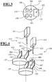
- Fig. 3 is a section taken along the line III-III Fig. 1 , This figure explains the course of the stereoscopic viewing beam paths 105, 205 of the surgical microscope 100 Fig. 1 ,
- the microscope main objective 101 is penetrated by two stereoscopic substraction gears 105, 205.
- the optical axis 102 of the microscope main objective lies in its center 310.
- the OCT scanning beam path 142 of the OCT system 140 is made out Fig. 1 passes through the microscope main objective 101 in the region 301. In the region 302, it becomes out of the OCT scanning beam path 152 of the OCT system 150 Fig. 2 and penetrated in the area 303 of the illumination light 122.
- Fig. 4 1 shows the first OCT system 140 and the second OCT system 150 in the surgical microscope 100 Fig. 1 respectively.
- Fig. 2 the wavelength range of the OCT scanning beam paths of the two OCT systems 140, 150 is different:
- To designate the assemblies of OCT systems 140 and 150 in FIG Fig. 4 are the same reference numerals as in Fig. 1 respectively. Fig. 2 used.
- the first scanning mirror 144, 154 and the second scanning mirror 145, 155 of the OCT systems 140, 150 are rotatably arranged about two mutually perpendicular axes 405, 406, 407 and 408 by means of actuators 401, 402, 403, 404. This makes it possible to scan the OCT scanning beam paths 142, 152 independently of one another via a plane.
- the OCT scanning beam 142 of the first OCT system 140 is guided to the microscope main lens 101 via the converging lens 147.
- the OCT scanning beam 152 of the second OCT system 150 passes through the main objective lens 101 via the converging lens 157.
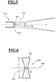
- Fig. 5 shows the front portion 502 of the light guide 143 Fig. 1 ,
- the diameter d 1 of the fiber core of the optical fiber 143 satisfies the relationship d 1 2 ⁇ 2.4 ⁇ 1 2 ⁇ N A 1 .
- NA 1 is the numerical aperture of the front face of the lightguide.
- the diameter d of the fiber core of the optical waveguide 122 is preferably in the range 5 ⁇ m ⁇ d ⁇ 10 ⁇ m.
- the front surface 502 of the light guide 143 is exposed via the scanning mirrors 144 and 145 in the surgical microscope 100 Fig. 1 , the condenser lens 147 imaged by the microscope main objective into an OCT scanning plane.
- the Fig. 6 shows the course of the intensity distribution of the OCT scanning light beam 501 perpendicular to the OCT scanning plane 601.
- the OCT scanning plane 601 has the Intensity distribution of the OCT scanning radiation a smallest constriction. Outside the OCT scanning plane, the diameter of the OCT scanning beam path increases. Since the OCT scanning light beam 501 is out of the light guide 143 Fig. 5 emerges with an approximately gaussian radiation profile, cause the converging lens 147 and the microscope main lens 101 of the surgical microscope 100 from Fig. 1 for the OCT scanning light beam in the area of the OCT scanning plane 160, a so-called Gaussbündel 600 of the OCT scanning light beam 501.
- ⁇ 1 is the enlargement or reduction parameter of the above-mentioned geometric image of the exit end of optical fiber 143 Fig. 1 is in the OCT scanning plane.
- the size of structures which can be resolved with the OCT scanning light beam 501 is determined by its diameter in the OCT scanning plane 601, ie by the waist parameter W 1 determined. If, for example, an application requires a lateral resolution of the OCT system in the surgical microscope of approximately 40 ⁇ m, the cross section of the OCT scanning light beam 501 in the OCT scanning plane must be approximately 20 ⁇ m, according to the Nyquist theorem. At a given wavelength ⁇ 1, for the OCT scanning light beam 143 Fig. 1 Therefore, for a desired resolution of the OCT system 140, the magnification of the optical image in the OCT beam path and the diameter of the fiber core in the light guide 143 must be suitably selected.
- the confocal parameter z 1 as a measure of the longitudinal extent of the waist of the Gauss beam determines the axial depth range from that in the OCT scanning beam 143 Fig. 1 backscattered light can be detected: the smaller the confocal parameter z 1 , the greater the loss of the OCT system at lateral resolution on removal of an object scanned in the OCT scanning radiation from the OCT scanning plane 601, since the location of scattering centers is only within of the "funnel" defined by the waist parameter W 1 and the confocal parameter z 1 .
- the axial resolution of an OCT system is limited by the coherence length l c of the light of the light source used in the OCT system, and on the other hand, the lateral resolution of the OCT system decreases when its depth stroke exceeds the confocal parameter, setting the confocal parameter z 1 on the coherence length l c of the light source used in the OCT system low.
- the possible lateral resolution of the OCT system then results Fig. 1 since the wavelength ⁇ 1 and the Rayleigh parameter z 1 define the waist parameter W 1, A.
- the optical units in the OCT scanning beam 143 from Fig. 1 and the dimensioning of the fiber core of light guide 143 are then to be chosen such that the respective waist parameter is realized.
- the converging lens 147 in the surgical microscope 100 is preferably adjusted so that the focal plane 170 of the microscope main objective 101 for the visible spectral range and the OCT scan plane 160 of the OCT system 140 coincide. Then lies the in Fig. 5 shown waist 502 of the OCT scanning beam in the focal plane of the surgical microscope.
- the diameter d 2 of the fiber core of the optical fiber 153 therefore satisfies the relationship: d 2 2 ⁇ 2.4 ⁇ 2 2 ⁇ N A 2 .
- NA 2 is the numerical aperture of the front surface of the light guide 153.
- W 2, A ⁇ 2 W 2 .
- ⁇ 2 is the enlargement or reduction parameter of the geometric image of the exit end of optical fiber 153 Fig. 2 in the OCT scanning plane 170.
- ⁇ 2 is characterized by the focal length of the converging lens 157 Fig. 2 , the focal length of the main microscope body 101 and the reduction lens 131, the ophthalmoscope magnifier 132, and the cornea and lens of the patient's eye 108.
- the converging lens 157 is preferably adjusted so that when the optical observation beam path through the microscope main objective 101 images the ocular fundus 190 of the patient's eye 108, the OCT scanning plane 170 for the OCT system 150 in the surgical microscope 100 coincides with the ocular fundus 190.
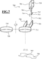
- FIG. 7 A modified embodiment for an OCT system shown in the ophthalmic surgical microscope 100 of FIG Fig. 1 and Fig. 2 can be used.
- the OCT system 700 includes according to the OCT system 140 Fig. 1 a unit 701 for the generation and analysis of an OCT scanning beam path 702.
- the unit 701 is designed so that OCT scanning beam paths with different wavelengths can be generated and evaluated.
- a controller 703 is provided for adjusting the wavelength of the OCT system 700.
- the OCT scanning beam 702 exits from a light guide 704 connected to the unit 701.
- a magnification changer 709 is provided as the lens changing device, which contains converging lenses of different refractive power 710, 711. These converging lenses 710, 711 can be pivoted into and out of the OCT scanning beam path 702.
- optical fiber 704 associated with a drive unit 712, which makes it possible to move the light-emitting exit end 713 corresponding to the double arrows 714, in order to be able to vary the position of the OCT scanning plane 707 in the object area.
- the OCT scanning beam 707 passes through the converging lens 709, which bundles the scanning beam and forwards to the microscope main objective of the corresponding operating microscope.
- Fig. 8 shows a further embodiment of an OCT system for an ophthalmic surgical microscope.
- the OCT system like the OCT system 700, has a unit 801 for the generation and analysis of an OCT scanning beam path 802 exiting the one light guide 803.
- the OCT scanning beam 802 exiting the optical fiber exit end 804 is guided via a corresponding scanning mirror system 805 through an adjustable power lens unit 806 which acts as a zoom system.
- an adjustable power lens unit 806 acts as a zoom system.
- Surgical microscope 100 includes a focusable microscope main objective with adjustable focal length. This measure also makes it possible to shift an OCT scanning plane and to change the geometric image of the light guide exit end into the OCT scanning plane.
Landscapes
- Health & Medical Sciences (AREA)
- Life Sciences & Earth Sciences (AREA)
- Physics & Mathematics (AREA)
- General Physics & Mathematics (AREA)
- General Health & Medical Sciences (AREA)
- Biomedical Technology (AREA)
- Medical Informatics (AREA)
- Biophysics (AREA)
- Ophthalmology & Optometry (AREA)
- Engineering & Computer Science (AREA)
- Nuclear Medicine, Radiotherapy & Molecular Imaging (AREA)
- Heart & Thoracic Surgery (AREA)
- Radiology & Medical Imaging (AREA)
- Molecular Biology (AREA)
- Surgery (AREA)
- Animal Behavior & Ethology (AREA)
- Public Health (AREA)
- Veterinary Medicine (AREA)
- Eye Examination Apparatus (AREA)
- Investigating Or Analysing Materials By Optical Means (AREA)
- Microscoopes, Condenser (AREA)
Claims (9)
- Microscope d'opération ophtalmologique, comportant- un objectif principal de microscope (101) ;- un chemin de faisceau d'observation (105, 205) qui traverse l'objectif principal de microscope (101) pour visualiser une zone objet (108) ; et- un système OCT (140, 150, 700, 800) destiné à acquérir des images de la zone objet (108), dans lequel le système OCT (140, 150, 700, 800) comprend un chemin de faisceau d'échantillonnage OCT (142, 152, 702, 802) qui est guidé par l'intermédiaire d'un dispositif à miroirs de balayage (146, 156, 705, 706, 805) vers la zone objet (108) ;caractérisé en ce qu'il est prévu- un module adaptateur ophtalmoscopique (130), comportant une loupe ophtalmoscopique (132) et une lentille réductrice (131), qui peut être introduit dans le faisceau d'observation (105, 205) et le chemin de faisceau d'échantillonnage OCT (142, 152) et en être sorti, et en ce qu'il est prévu- un couplage entre le système OCT (140) et la loupe ophtalmoscopique (132) de manière à ce que, lorsque la loupe ophtalmoscopique (132) est introduite dans le faisceau, la longueur de trajet optique sur le chemin du faisceau de référence du système OCT est augmentée d'une valeur déterminée qui est maintenue réglable.
- Microscope d'opération ophtalmologique selon la revendication 1, caractérisé en ce qu'il est prévu :- entre le dispositif à miroirs de balayage (146, 156, 705, 706, 805) et l'objectif principal de microscope (101) un élément optique (147, 157, 711, 806) qui focalise le chemin de faisceau d'échantillonnage OCT (142, 152, 702, 802) sortant du dispositif à miroirs de balayage (146, 156, 705, 706, 805) et le transfère sur un chemin de faisceau passant à travers l'objectif principal de microscope (101).
- Microscope d'opération ophtalmologique selon la revendication 2, caractérisé en ce que l'élément optique est réalisé sous la forme d'une unité à lentille mobile (147, 157).
- Microscope d'opération ophtalmologique selon la revendication 2 ou 3, caractérisé en ce que l'élément optique (711) est logé dans un moyen d'échange de lentilles (709).
- Microscope d'opération ophtalmologique selon la revendication, caractérisé en ce que l'élément optique est réalisé sous la forme d'un système de zoom (806) à focale variable.
- Microscope d'opération ophtalmologique selon l'une quelconque des revendications 2 à 5, caractérisé en ce qu'il est prévu des moyens destinés à régler la longueur focale de l'objectif principal de microscope.
- Microscope d'opération ophtalmologique selon l'une quelconque des revendications 2 à 6, caractérisé en ce que le dispositif à miroirs de balayage (146, 156) comprend, pour animer d'un mouvement de balayage le chemin de faisceau d'échantillonnage OCT, un premier miroir de balayage (144, 154) qui peut être déplacé autour d'un premier axe de rotation (301, 303).
- Microscope d'opération ophtalmologique selon la revendication 7, caractérisé en ce qu'il est prévu un deuxième miroir de balayage (145, 155) qui peut être déplacé autour d'un deuxième axe de rotation (302, 304), dans lequel le premier axe de rotation (301, 303) et le deuxième axe de rotation (302, 304) sont décalés latéralement l'un par rapport à l'autre en formant un angle droit.
- Microscope d'opération ophtalmologique selon l'une quelconque des revendications 2 à 8, caractérisé en ce que le système OCT comprend un guide optique (704) qui présente une section de sortie de lumière (713) destinée au chemin de faisceau d'échantillonnage OCT, dans lequel il est prévu des moyens (712) destinés à déplacer la section de sortie de lumière (713) du guide optique (704).
Applications Claiming Priority (3)
| Application Number | Priority Date | Filing Date | Title |
|---|---|---|---|
| DE102006052513 | 2006-11-06 | ||
| DE102007019680A DE102007019680A1 (de) | 2006-11-06 | 2007-04-24 | Ophthalmo-Operationsmikroskop mit OCT-System |
| EP07019795A EP1918755B1 (fr) | 2006-11-06 | 2007-10-10 | Microscope d'opération ophtalmique doté d'un système OCT |
Related Parent Applications (2)
| Application Number | Title | Priority Date | Filing Date |
|---|---|---|---|
| EP07019795A Division EP1918755B1 (fr) | 2006-11-06 | 2007-10-10 | Microscope d'opération ophtalmique doté d'un système OCT |
| EP07019795.9 Division | 2007-10-10 |
Publications (2)
| Publication Number | Publication Date |
|---|---|
| EP2482113A1 EP2482113A1 (fr) | 2012-08-01 |
| EP2482113B1 true EP2482113B1 (fr) | 2017-12-27 |
Family
ID=38926425
Family Applications (2)
| Application Number | Title | Priority Date | Filing Date |
|---|---|---|---|
| EP07019795A Revoked EP1918755B1 (fr) | 2006-11-06 | 2007-10-10 | Microscope d'opération ophtalmique doté d'un système OCT |
| EP12165225.9A Active EP2482113B1 (fr) | 2006-11-06 | 2007-10-10 | Microscope d'opération doté d'un système OCT |
Family Applications Before (1)
| Application Number | Title | Priority Date | Filing Date |
|---|---|---|---|
| EP07019795A Revoked EP1918755B1 (fr) | 2006-11-06 | 2007-10-10 | Microscope d'opération ophtalmique doté d'un système OCT |
Country Status (5)
| Country | Link |
|---|---|
| US (2) | US7839494B2 (fr) |
| EP (2) | EP1918755B1 (fr) |
| JP (1) | JP5243774B2 (fr) |
| DE (1) | DE102007019680A1 (fr) |
| ES (2) | ES2662717T3 (fr) |
Families Citing this family (44)
| Publication number | Priority date | Publication date | Assignee | Title |
|---|---|---|---|---|
| US7952722B2 (en) * | 2007-12-12 | 2011-05-31 | Kabushiki Kaisha Topcon | Optical image measurement device |
| US8049873B2 (en) | 2008-03-19 | 2011-11-01 | Carl Zeiss Meditec Ag | Surgical microscopy system having an optical coherence tomography facility |
| DE102008041284B4 (de) * | 2008-05-07 | 2010-05-27 | Carl Zeiss Surgical Gmbh | Ophthalmo-Operationsmikroskopsystem mit OCT-Messeinrichtung |
| US8459795B2 (en) | 2008-09-16 | 2013-06-11 | Carl Zeiss Meditec Ag | Measuring system for ophthalmic surgery |
| JP4732548B2 (ja) | 2008-10-17 | 2011-07-27 | オリンパスメディカルシステムズ株式会社 | 内視鏡システムおよび内視鏡画像処理装置 |
| JP5632386B2 (ja) | 2008-11-26 | 2014-11-26 | カール ツアイス メディテック アクチエンゲゼルシャフト | 画像化システム |
| DE102008059876B4 (de) * | 2008-12-01 | 2010-08-05 | Carl Zeiss Surgical Gmbh | Ophthalmoskopie-System und Ophthalmoskopie-Verfahren |
| DE102009037708B4 (de) | 2009-08-17 | 2019-02-21 | Carl Zeiss Meditec Ag | Erzeugnis zur Verwendung in einem OCT-Verfahren und Intraokularlinse |
| US8287126B2 (en) | 2010-01-15 | 2012-10-16 | Carl Zeiss Meditec Ag | System and method for visualizing objects |
| US8366271B2 (en) | 2010-01-20 | 2013-02-05 | Duke University | Systems and methods for surgical microscope and optical coherence tomography (OCT) imaging |
| JP2011212432A (ja) * | 2010-03-15 | 2011-10-27 | Nidek Co Ltd | 眼科撮影装置 |
| DE102011114523A1 (de) * | 2011-09-29 | 2013-04-04 | Carl Zeiss Meditec Ag | Modul zur Weiterleitung eines Lichtstrahls |
| WO2013081252A1 (fr) * | 2011-12-01 | 2013-06-06 | 경북대학교 산학협력단 | Microscope pour surveiller une tomographie par cohérence optique |
| EP2790570B1 (fr) | 2011-12-05 | 2019-09-04 | Bioptigen, Inc. | Systèmes d'imagerie optique comprenant une régulation de forme de faisceau entrant et une régulation de longueur de trajet |
| US8777412B2 (en) | 2012-04-05 | 2014-07-15 | Bioptigen, Inc. | Surgical microscopes using optical coherence tomography and related methods |
| JP6373366B2 (ja) | 2013-06-04 | 2018-08-15 | バイオプティジェン, インコーポレイテッドBioptigen, Inc. | 走査ビーム型システムの作動方法および光走査ビーム型システム |
| WO2015017375A2 (fr) | 2013-07-29 | 2015-02-05 | Bioptigen, Inc. | Tomographie par cohérence optique (oct) procédurale pour la chirurgie et systèmes et procédés associés |
| CN105612453B (zh) | 2013-08-28 | 2018-03-27 | 拜尔普泰戈恩公司 | 用于光学相干断层成像集成外科显微镜的抬头显示器 |
| DE102013219383B3 (de) | 2013-09-26 | 2015-03-12 | Carl Zeiss Meditec Ag | Optisches Abbildungssystem |
| DE102013219379B3 (de) | 2013-09-26 | 2015-03-12 | Carl Zeiss Meditec Ag | Optisches Abbildungssystem |
| EP2921099A1 (fr) * | 2014-03-18 | 2015-09-23 | Dieter Mann GmbH | Adaptateur d'ophtalmoscopie pour microscope opératoire |
| CH711778B1 (de) | 2014-09-19 | 2019-06-14 | Zeiss Carl Meditec Ag | System zur optischen Kohärenztomographie, umfassend ein zoombares Kepler-System. |
| US10835119B2 (en) | 2015-02-05 | 2020-11-17 | Duke University | Compact telescope configurations for light scanning systems and methods of using the same |
| US10238279B2 (en) | 2015-02-06 | 2019-03-26 | Duke University | Stereoscopic display systems and methods for displaying surgical data and information in a surgical microscope |
| JP6456711B2 (ja) * | 2015-02-16 | 2019-01-23 | 株式会社トプコン | 眼科手術用顕微鏡および眼科手術用アタッチメント |
| JP2016202453A (ja) * | 2015-04-20 | 2016-12-08 | 株式会社トプコン | 眼科手術用顕微鏡 |
| US9693686B2 (en) * | 2015-04-30 | 2017-07-04 | Novartis Ag | Ophthalmic visualization devices, systems, and methods |
| US10694939B2 (en) | 2016-04-29 | 2020-06-30 | Duke University | Whole eye optical coherence tomography(OCT) imaging systems and related methods |
| DE102017105580A1 (de) * | 2016-11-04 | 2018-05-09 | Carl Zeiss Meditec Ag | Operationsmikroskop |
| JP7042663B2 (ja) * | 2017-03-30 | 2022-03-28 | 株式会社トプコン | 眼科用顕微鏡 |
| WO2018203174A1 (fr) | 2017-05-02 | 2018-11-08 | Novartis Ag | Système de tomographie par cohérence optique (oct) reconfigurable |
| WO2018203577A1 (fr) | 2017-05-02 | 2018-11-08 | 株式会社トプコン | Microscope ophtalmique et unité d'amélioration de fonctionnalité |
| WO2018216788A1 (fr) | 2017-05-25 | 2018-11-29 | 株式会社トプコン | Microscope ophtalmique et unité d'extension de fonction |
| EP3636137B1 (fr) | 2017-05-25 | 2024-04-17 | Topcon Corporation | Microscope ophtalmique et unité d'extension de fonction |
| JP7329308B2 (ja) * | 2017-07-05 | 2023-08-18 | 株式会社ニデック | Oct装置および光学アタッチメント |
| KR101931540B1 (ko) * | 2017-07-31 | 2018-12-24 | 주식회사 고영테크놀러지 | 스테레오 현미경, 광학 장치 및 이를 이용한 광경로 형성 방법 |
| JP7213378B2 (ja) * | 2017-08-31 | 2023-01-26 | 株式会社トプコン | Oct機能拡張ユニット |
| CN108852617B (zh) * | 2018-05-18 | 2021-06-25 | 深圳市斯尔顿科技有限公司 | 一种眼科手术显微镜系统 |
| CN108577802B (zh) * | 2018-05-18 | 2021-02-26 | 深圳市斯尔顿科技有限公司 | 结合oct成像的眼科手术显微镜系统 |
| JP6638050B2 (ja) * | 2018-10-23 | 2020-01-29 | 株式会社トプコン | 眼科手術用顕微鏡および眼科手術用アタッチメント |
| CN110231623A (zh) * | 2019-04-22 | 2019-09-13 | 电子科技大学 | 一种探测等离子体性质的准光光路装置 |
| CN110793465B (zh) * | 2019-11-07 | 2021-07-20 | 中国计量大学 | 一种微透射元件多面形大动态范围同步测量方法 |
| CN115634098B (zh) * | 2022-10-25 | 2023-08-01 | 重庆贝奥新视野医疗设备有限公司 | 一种高速眼科手术导航oct系统及实现方法 |
| CN116548911B (zh) * | 2023-05-19 | 2023-12-08 | 北京至真互联网技术有限公司 | 一种基于oct技术的眼部血管成像方法及系统 |
Family Cites Families (23)
| Publication number | Priority date | Publication date | Assignee | Title |
|---|---|---|---|---|
| US5321501A (en) | 1991-04-29 | 1994-06-14 | Massachusetts Institute Of Technology | Method and apparatus for optical imaging with means for controlling the longitudinal range of the sample |
| US5535052A (en) * | 1992-07-24 | 1996-07-09 | Carl-Zeiss-Stiftung | Laser microscope |
| ES2233727T3 (es) | 1994-08-18 | 2005-06-16 | Carl Zeiss Meditec Ag | Aparato quirurgico asistido por tomografia de coherencia optica. |
| US5493109A (en) | 1994-08-18 | 1996-02-20 | Carl Zeiss, Inc. | Optical coherence tomography assisted ophthalmologic surgical microscope |
| DE9415219U1 (de) * | 1994-09-22 | 1994-11-24 | Oculus Optikgeräte GmbH, 35582 Wetzlar | Vorsatzeinrichtung für ein Mikroskop |
| CH693804A5 (de) * | 1994-10-13 | 2004-02-13 | Zeiss Carl Fa | Beleuchtungseinrichtung für ein Stereomikroskop. |
| US5795295A (en) * | 1996-06-25 | 1998-08-18 | Carl Zeiss, Inc. | OCT-assisted surgical microscope with multi-coordinate manipulator |
| ES2183447T3 (es) * | 1998-03-09 | 2003-03-16 | Medizinisches Laserzentrum Lub | Procedimiento y dispositivo destinados a examinar un segmento ocular. |
| JP2001108906A (ja) * | 1999-10-01 | 2001-04-20 | Topcon Corp | 手術用顕微鏡 |
| DE10140402B4 (de) * | 2000-09-26 | 2012-08-30 | Carl Zeiss Meditec Ag | Bildumkehrsystem, Ophthalmoskopie-Vorsatzmodul und Operationsmikroskop |
| DE10064909A1 (de) * | 2000-12-23 | 2002-07-04 | Leica Microsystems | Einrichtung zur Helligkeitssteuerung von überlagerten Zusatzinformationen in einer optischen Betrachtungseinrichtung |
| DE10110389A1 (de) * | 2001-03-03 | 2002-09-12 | Zeiss Carl | Verfahren zur Justierung einer Lampe relativ zu einem Beleuchtungsstrahlengang eines Mikroskopes und zur Ausführung des Verfahrens geeignetes Mikroskop |
| US6726325B2 (en) * | 2002-02-26 | 2004-04-27 | Carl Zeiss Meditec, Inc. | Tracking assisted optical coherence tomography |
| US6741359B2 (en) * | 2002-05-22 | 2004-05-25 | Carl Zeiss Meditec, Inc. | Optical coherence tomography optical scanner |
| DE10302401A1 (de) * | 2003-01-21 | 2004-07-29 | Leica Microsystems (Schweiz) Ag | Operationsmikroskop |
| EP1498762A1 (fr) * | 2003-07-17 | 2005-01-19 | Leica Microsystems (Schweiz) AG | Microscope |
| WO2006010379A1 (fr) | 2004-07-29 | 2006-02-02 | Actelion Pharmaceuticals Ltd. | Nouveaux derives du thiophene utilises comme agents immunosupresseurs |
| DE102004049368A1 (de) | 2004-10-09 | 2006-04-13 | Carl Zeiss Ag | Operationsmikroskop mit Binokulartubus für Mitbeobachtung |
| US20060176550A1 (en) * | 2005-02-07 | 2006-08-10 | Christian Luecke | Tube for a viewing device as well as a viewing device |
| US20090015842A1 (en) | 2005-03-21 | 2009-01-15 | Rainer Leitgeb | Phase Sensitive Fourier Domain Optical Coherence Tomography |
| ATE486520T1 (de) * | 2005-09-29 | 2010-11-15 | Bioptigen Inc | Tragbare optische kohärenz-tomographie- vorrichtungen und verwandte systeme |
| JP2007230834A (ja) * | 2006-03-02 | 2007-09-13 | Konica Minolta Opto Inc | 光学ガラス素子の成形方法 |
| US8042944B2 (en) * | 2007-03-20 | 2011-10-25 | Topcon Europe Medical B.V. | Apparatus and method for observing an eye, as well as OCT-module |
-
2007
- 2007-04-24 DE DE102007019680A patent/DE102007019680A1/de active Pending
- 2007-10-10 ES ES12165225.9T patent/ES2662717T3/es active Active
- 2007-10-10 EP EP07019795A patent/EP1918755B1/fr not_active Revoked
- 2007-10-10 ES ES07019795T patent/ES2399353T3/es active Active
- 2007-10-10 EP EP12165225.9A patent/EP2482113B1/fr active Active
- 2007-11-08 JP JP2007290532A patent/JP5243774B2/ja active Active
- 2007-11-21 US US11/984,819 patent/US7839494B2/en active Active
-
2010
- 2010-08-04 US US12/805,518 patent/US8023120B2/en active Active
Non-Patent Citations (1)
| Title |
|---|
| None * |
Also Published As
| Publication number | Publication date |
|---|---|
| US7839494B2 (en) | 2010-11-23 |
| EP2482113A1 (fr) | 2012-08-01 |
| US8023120B2 (en) | 2011-09-20 |
| EP1918755B1 (fr) | 2012-12-05 |
| JP2008268852A (ja) | 2008-11-06 |
| ES2662717T3 (es) | 2018-04-09 |
| US20080117432A1 (en) | 2008-05-22 |
| JP5243774B2 (ja) | 2013-07-24 |
| ES2399353T3 (es) | 2013-03-27 |
| DE102007019680A1 (de) | 2008-05-08 |
| US20100309478A1 (en) | 2010-12-09 |
| EP1918755A1 (fr) | 2008-05-07 |
Similar Documents
| Publication | Publication Date | Title |
|---|---|---|
| EP2482113B1 (fr) | Microscope d'opération doté d'un système OCT | |
| EP1918756B1 (fr) | Microscope d'opération doté d'un système OCT et module d'éclairage de microscope d'opération doté d'un système OCT | |
| EP1918754B1 (fr) | Microscope d'opération doté d'un système OCT | |
| EP1918753B1 (fr) | Microscope d'opération doté d'un système OCT | |
| DE102008041284B4 (de) | Ophthalmo-Operationsmikroskopsystem mit OCT-Messeinrichtung | |
| DE102016001659B4 (de) | Augenoperationsmikroskop und Augenoperationszusatzgerät | |
| DE69533903T2 (de) | Mit optischer Kohärenz-Tomographie gesteuerter chirurgischer Apparat | |
| EP0941692B1 (fr) | Méthode et dispositif d'examen de l'oeil | |
| DE102016203487B4 (de) | Augenmikroskopsystem | |
| WO2016041640A1 (fr) | Système de tomographie par cohérence optique comprenant un système kepler zoomable | |
| WO2010031540A2 (fr) | Système de mesure utilisé en chirurgie ophtalmologique | |
| DE102005046690A1 (de) | Vorrichtung zur auf spektraler interferenz basierender optischer Kohärenztomographie und ophthalmologische Vorrichtung | |
| DE10351319A1 (de) | Interferometer zur optischen Kohärenztomographie | |
| DE102016203473A1 (de) | Augenmikroskop | |
| EP2301425A1 (fr) | Ophtalmoscope pour l'observation d'un oeil | |
| WO2013189591A1 (fr) | Microscope pour chirurgie oculaire, présentant un dispositif de mesure de l'amétropie | |
| WO2012084170A9 (fr) | Dispositif de mesure par interférométrie de la longueur de l'œil et de la partie antérieure de l'œil | |
| EP1889567A2 (fr) | Module d'ophtalmoscopie pour un microscope d'opération | |
| DE60204178T2 (de) | Aberrationsfreie Abbildung des Augenhintergrundes | |
| DE102018118352A1 (de) | Ophthalmologisches Operationsmikroskop | |
| JP2013137541A (ja) | Octシステムを備える眼科手術用顕微鏡 | |
| DE102011114523A1 (de) | Modul zur Weiterleitung eines Lichtstrahls | |
| WO2013079214A1 (fr) | Système de microscopie pour les examens oculaires et système oct | |
| DE102023109837A1 (de) | Beleuchtungsvorrichtung, Faserendoskop und Verfahren zum Ermitteln einer Übertragungseigenschaft einer Beleuchtungsfaser | |
| DE102008059876B4 (de) | Ophthalmoskopie-System und Ophthalmoskopie-Verfahren |
Legal Events
| Date | Code | Title | Description |
|---|---|---|---|
| PUAI | Public reference made under article 153(3) epc to a published international application that has entered the european phase |
Free format text: ORIGINAL CODE: 0009012 |
|
| 17P | Request for examination filed |
Effective date: 20120423 |
|
| AC | Divisional application: reference to earlier application |
Ref document number: 1918755 Country of ref document: EP Kind code of ref document: P |
|
| AK | Designated contracting states |
Kind code of ref document: A1 Designated state(s): DE ES FR GB IT |
|
| 17Q | First examination report despatched |
Effective date: 20131017 |
|
| GRAP | Despatch of communication of intention to grant a patent |
Free format text: ORIGINAL CODE: EPIDOSNIGR1 |
|
| STAA | Information on the status of an ep patent application or granted ep patent |
Free format text: STATUS: GRANT OF PATENT IS INTENDED |
|
| RIC1 | Information provided on ipc code assigned before grant |
Ipc: A61B 3/12 20060101ALI20170720BHEP Ipc: G01B 9/02 20060101ALI20170720BHEP Ipc: A61B 5/00 20060101ALI20170720BHEP Ipc: G02B 21/00 20060101AFI20170720BHEP Ipc: A61B 3/13 20060101ALI20170720BHEP |
|
| INTG | Intention to grant announced |
Effective date: 20170814 |
|
| GRAS | Grant fee paid |
Free format text: ORIGINAL CODE: EPIDOSNIGR3 |
|
| GRAA | (expected) grant |
Free format text: ORIGINAL CODE: 0009210 |
|
| STAA | Information on the status of an ep patent application or granted ep patent |
Free format text: STATUS: THE PATENT HAS BEEN GRANTED |
|
| AC | Divisional application: reference to earlier application |
Ref document number: 1918755 Country of ref document: EP Kind code of ref document: P |
|
| AK | Designated contracting states |
Kind code of ref document: B1 Designated state(s): DE ES FR GB IT |
|
| REG | Reference to a national code |
Ref country code: GB Ref legal event code: FG4D Free format text: NOT ENGLISH |
|
| REG | Reference to a national code |
Ref country code: DE Ref legal event code: R096 Ref document number: 502007015999 Country of ref document: DE |
|
| REG | Reference to a national code |
Ref country code: ES Ref legal event code: FG2A Ref document number: 2662717 Country of ref document: ES Kind code of ref document: T3 Effective date: 20180409 |
|
| REG | Reference to a national code |
Ref country code: DE Ref legal event code: R097 Ref document number: 502007015999 Country of ref document: DE |
|
| REG | Reference to a national code |
Ref country code: FR Ref legal event code: PLFP Year of fee payment: 12 |
|
| PLBE | No opposition filed within time limit |
Free format text: ORIGINAL CODE: 0009261 |
|
| STAA | Information on the status of an ep patent application or granted ep patent |
Free format text: STATUS: NO OPPOSITION FILED WITHIN TIME LIMIT |
|
| 26N | No opposition filed |
Effective date: 20180928 |
|
| P01 | Opt-out of the competence of the unified patent court (upc) registered |
Effective date: 20230530 |
|
| PGFP | Annual fee paid to national office [announced via postgrant information from national office to epo] |
Ref country code: GB Payment date: 20231020 Year of fee payment: 17 |
|
| PGFP | Annual fee paid to national office [announced via postgrant information from national office to epo] |
Ref country code: ES Payment date: 20231222 Year of fee payment: 17 |
|
| PGFP | Annual fee paid to national office [announced via postgrant information from national office to epo] |
Ref country code: IT Payment date: 20231026 Year of fee payment: 17 Ref country code: FR Payment date: 20231024 Year of fee payment: 17 |
|
| PGFP | Annual fee paid to national office [announced via postgrant information from national office to epo] |
Ref country code: DE Payment date: 20241021 Year of fee payment: 18 |