EP2481939B1 - Spannschelle - Google Patents
Spannschelle Download PDFInfo
- Publication number
- EP2481939B1 EP2481939B1 EP11008901.8A EP11008901A EP2481939B1 EP 2481939 B1 EP2481939 B1 EP 2481939B1 EP 11008901 A EP11008901 A EP 11008901A EP 2481939 B1 EP2481939 B1 EP 2481939B1
- Authority
- EP
- European Patent Office
- Prior art keywords
- legs
- spring clip
- threaded nut
- clamping collar
- clamping
- Prior art date
- Legal status (The legal status is an assumption and is not a legal conclusion. Google has not performed a legal analysis and makes no representation as to the accuracy of the status listed.)
- Active
Links
- 239000000463 material Substances 0.000 description 6
- 238000004519 manufacturing process Methods 0.000 description 5
- 238000003780 insertion Methods 0.000 description 3
- 230000037431 insertion Effects 0.000 description 3
- 238000003860 storage Methods 0.000 description 3
- 238000005452 bending Methods 0.000 description 2
- 239000002184 metal Substances 0.000 description 2
- 238000000034 method Methods 0.000 description 2
- 230000007423 decrease Effects 0.000 description 1
- 238000009434 installation Methods 0.000 description 1
- 238000004080 punching Methods 0.000 description 1
- 210000002105 tongue Anatomy 0.000 description 1
Images

Classifications
-
- F—MECHANICAL ENGINEERING; LIGHTING; HEATING; WEAPONS; BLASTING
- F16—ENGINEERING ELEMENTS AND UNITS; GENERAL MEASURES FOR PRODUCING AND MAINTAINING EFFECTIVE FUNCTIONING OF MACHINES OR INSTALLATIONS; THERMAL INSULATION IN GENERAL
- F16B—DEVICES FOR FASTENING OR SECURING CONSTRUCTIONAL ELEMENTS OR MACHINE PARTS TOGETHER, e.g. NAILS, BOLTS, CIRCLIPS, CLAMPS, CLIPS OR WEDGES; JOINTS OR JOINTING
- F16B37/00—Nuts or like thread-engaging members
- F16B37/04—Devices for fastening nuts to surfaces, e.g. sheets, plates
- F16B37/044—Nut cages
-
- F—MECHANICAL ENGINEERING; LIGHTING; HEATING; WEAPONS; BLASTING
- F16—ENGINEERING ELEMENTS AND UNITS; GENERAL MEASURES FOR PRODUCING AND MAINTAINING EFFECTIVE FUNCTIONING OF MACHINES OR INSTALLATIONS; THERMAL INSULATION IN GENERAL
- F16B—DEVICES FOR FASTENING OR SECURING CONSTRUCTIONAL ELEMENTS OR MACHINE PARTS TOGETHER, e.g. NAILS, BOLTS, CIRCLIPS, CLAMPS, CLIPS OR WEDGES; JOINTS OR JOINTING
- F16B2/00—Friction-grip releasable fastenings
- F16B2/02—Clamps, i.e. with gripping action effected by positive means other than the inherent resistance to deformation of the material of the fastening
-
- F—MECHANICAL ENGINEERING; LIGHTING; HEATING; WEAPONS; BLASTING
- F16—ENGINEERING ELEMENTS AND UNITS; GENERAL MEASURES FOR PRODUCING AND MAINTAINING EFFECTIVE FUNCTIONING OF MACHINES OR INSTALLATIONS; THERMAL INSULATION IN GENERAL
- F16B—DEVICES FOR FASTENING OR SECURING CONSTRUCTIONAL ELEMENTS OR MACHINE PARTS TOGETHER, e.g. NAILS, BOLTS, CIRCLIPS, CLAMPS, CLIPS OR WEDGES; JOINTS OR JOINTING
- F16B37/00—Nuts or like thread-engaging members
- F16B37/04—Devices for fastening nuts to surfaces, e.g. sheets, plates
- F16B37/041—Releasable devices
- F16B37/043—Releasable devices with snap action
-
- F—MECHANICAL ENGINEERING; LIGHTING; HEATING; WEAPONS; BLASTING
- F16—ENGINEERING ELEMENTS AND UNITS; GENERAL MEASURES FOR PRODUCING AND MAINTAINING EFFECTIVE FUNCTIONING OF MACHINES OR INSTALLATIONS; THERMAL INSULATION IN GENERAL
- F16B—DEVICES FOR FASTENING OR SECURING CONSTRUCTIONAL ELEMENTS OR MACHINE PARTS TOGETHER, e.g. NAILS, BOLTS, CIRCLIPS, CLAMPS, CLIPS OR WEDGES; JOINTS OR JOINTING
- F16B7/00—Connections of rods or tubes, e.g. of non-circular section, mutually, including resilient connections
- F16B7/04—Clamping or clipping connections
-
- F—MECHANICAL ENGINEERING; LIGHTING; HEATING; WEAPONS; BLASTING
- F16—ENGINEERING ELEMENTS AND UNITS; GENERAL MEASURES FOR PRODUCING AND MAINTAINING EFFECTIVE FUNCTIONING OF MACHINES OR INSTALLATIONS; THERMAL INSULATION IN GENERAL
- F16L—PIPES; JOINTS OR FITTINGS FOR PIPES; SUPPORTS FOR PIPES, CABLES OR PROTECTIVE TUBING; MEANS FOR THERMAL INSULATION IN GENERAL
- F16L33/00—Arrangements for connecting hoses to rigid members; Rigid hose connectors, i.e. single members engaging both hoses
- F16L33/02—Hose-clips
- F16L33/04—Hose-clips tightened by tangentially-arranged threaded pin and nut
-
- Y—GENERAL TAGGING OF NEW TECHNOLOGICAL DEVELOPMENTS; GENERAL TAGGING OF CROSS-SECTIONAL TECHNOLOGIES SPANNING OVER SEVERAL SECTIONS OF THE IPC; TECHNICAL SUBJECTS COVERED BY FORMER USPC CROSS-REFERENCE ART COLLECTIONS [XRACs] AND DIGESTS
- Y10—TECHNICAL SUBJECTS COVERED BY FORMER USPC
- Y10T—TECHNICAL SUBJECTS COVERED BY FORMER US CLASSIFICATION
- Y10T24/00—Buckles, buttons, clasps, etc.
- Y10T24/14—Bale and package ties, hose clamps
- Y10T24/1412—Bale and package ties, hose clamps with tighteners
- Y10T24/1441—Tangential screw
- Y10T24/1443—Adjustable girth
-
- Y—GENERAL TAGGING OF NEW TECHNOLOGICAL DEVELOPMENTS; GENERAL TAGGING OF CROSS-SECTIONAL TECHNOLOGIES SPANNING OVER SEVERAL SECTIONS OF THE IPC; TECHNICAL SUBJECTS COVERED BY FORMER USPC CROSS-REFERENCE ART COLLECTIONS [XRACs] AND DIGESTS
- Y10—TECHNICAL SUBJECTS COVERED BY FORMER USPC
- Y10T—TECHNICAL SUBJECTS COVERED BY FORMER US CLASSIFICATION
- Y10T24/00—Buckles, buttons, clasps, etc.
- Y10T24/14—Bale and package ties, hose clamps
- Y10T24/1412—Bale and package ties, hose clamps with tighteners
- Y10T24/1441—Tangential screw
- Y10T24/1451—Plural separable parts
-
- Y—GENERAL TAGGING OF NEW TECHNOLOGICAL DEVELOPMENTS; GENERAL TAGGING OF CROSS-SECTIONAL TECHNOLOGIES SPANNING OVER SEVERAL SECTIONS OF THE IPC; TECHNICAL SUBJECTS COVERED BY FORMER USPC CROSS-REFERENCE ART COLLECTIONS [XRACs] AND DIGESTS
- Y10—TECHNICAL SUBJECTS COVERED BY FORMER USPC
- Y10T—TECHNICAL SUBJECTS COVERED BY FORMER US CLASSIFICATION
- Y10T24/00—Buckles, buttons, clasps, etc.
- Y10T24/44—Clasp, clip, support-clamp, or required component thereof
- Y10T24/44291—Clasp, clip, support-clamp, or required component thereof including pivoted gripping member
- Y10T24/44376—Spring or resiliently biased about pivot
- Y10T24/44385—Distinct spring
- Y10T24/44402—Distinct spring with operator for moving pivoted member
-
- Y—GENERAL TAGGING OF NEW TECHNOLOGICAL DEVELOPMENTS; GENERAL TAGGING OF CROSS-SECTIONAL TECHNOLOGIES SPANNING OVER SEVERAL SECTIONS OF THE IPC; TECHNICAL SUBJECTS COVERED BY FORMER USPC CROSS-REFERENCE ART COLLECTIONS [XRACs] AND DIGESTS
- Y10—TECHNICAL SUBJECTS COVERED BY FORMER USPC
- Y10T—TECHNICAL SUBJECTS COVERED BY FORMER US CLASSIFICATION
- Y10T24/00—Buckles, buttons, clasps, etc.
- Y10T24/44—Clasp, clip, support-clamp, or required component thereof
- Y10T24/44641—Clasp, clip, support-clamp, or required component thereof having gripping member formed from, biased by, or mounted on resilient member
- Y10T24/44684—Clasp, clip, support-clamp, or required component thereof having gripping member formed from, biased by, or mounted on resilient member with operator for moving biased engaging face
-
- Y—GENERAL TAGGING OF NEW TECHNOLOGICAL DEVELOPMENTS; GENERAL TAGGING OF CROSS-SECTIONAL TECHNOLOGIES SPANNING OVER SEVERAL SECTIONS OF THE IPC; TECHNICAL SUBJECTS COVERED BY FORMER USPC CROSS-REFERENCE ART COLLECTIONS [XRACs] AND DIGESTS
- Y10—TECHNICAL SUBJECTS COVERED BY FORMER USPC
- Y10T—TECHNICAL SUBJECTS COVERED BY FORMER US CLASSIFICATION
- Y10T29/00—Metal working
- Y10T29/49—Method of mechanical manufacture
- Y10T29/49826—Assembling or joining
Definitions
- the invention relates to a clamp, with a clamping screw which cooperates with a polygonal nut.
- Such clamping elements serve, for example, to keep pipes or pipes on connecting pieces by the introduction of radial clamping forces.
- the clamping elements are tightened by tightening the clamping screw, wherein the clamping screw is screwed into the threaded nut.
- the nut and the clamping screw are each mounted on a clamping head of the clamp. Since when tightening the clamping screw the radius of the clamp decreases, the angular position between the nut and clamping screw changes. This increases the required actuating forces.
- DE 19 01 917 U relates to a clamp for hoses and pipes and discloses the preamble of claim 1.
- the clamp has here clamping body in box shape. Through openings in the clamping bodies while a clamping screw is guided, which engages in a threaded nut.
- EP 2 177 775 A1 discloses a system for assembling two parts.
- the system includes a clamping screw and a threaded nut.
- the threaded nut is held against rotation between two legs of a spring clip.
- US 2 695 046 A discloses a threaded nut and a clamping screw.
- the threaded nut is held against rotation in a spring clip.
- the spring clip comprises two legs.
- BE 499 584 A discloses a threaded nut held in a spring clip.
- the threaded nut can be brought into engagement with a clamping screw.
- the spring clip includes legs.
- DE 101 22 647 C1 discloses a pipe clamp comprising a clamp band and two jaws.
- the jaws can be moved towards each other with a clamping screw and a threaded nut to clamp the pipe clamp.
- the threaded nut is held against rotation by radially protruding tabs.
- US 2 571 747 A shows a fastening member for receiving and fixing a bolt.
- the fastening component is first inserted into an opening of a carrier until projections rest against an end face of the carrier. At the same time latch tongues on the front side opposite the projections of the carrier.
- the cage nut comprises a holder with which a nut can be pre-attached to an opening of a carrier.
- the holder for this purpose comprises U-shaped bent projections which engage around the carrier in a form-fitting manner in the region of the opening of both end faces.
- the invention is based on the object to make the storage of the threaded nut on the clamping element easy.
- a spring clip can be done relatively easily by forming a corresponding strip of material, for example metal or the like. It can be obtained by the use of the spring clip a relatively backlash-free storage, which is at the same time somewhat yielding to the action of external forces, so that can be done without problems, an angular compensation between the nut and clamping screw.
- the spring clip may be made of a different material than the clamping element and the threaded nut. The locking connection between spring clip and clamping element allows almost any combination of materials.
- the spring clip is substantially U-shaped and has a bottom and two legs.
- Such a design of the spring clip is relatively easy to produce. Through the two legs takes place an anti-rotation of the threaded nut, which can rest with one end face on the ground. At the same time the spring clip is held over the legs on the clamping element.
- the legs can for example produce a resilient holding force.
- the legs each have an inwardly directed first stage, wherein the threaded nut is held between the bottom and the first stage.
- the threaded nut is thus held positively in the spring clip.
- the forces occurring when screwing the screw into the threaded nut are absorbed by the spring clip.
- a slight pivoting between the spring clip and the clamping element according to the invention may be possible. This is to facilitate the threading of the threaded screw during assembly.
- retaining tabs Preferably go from the bottom of at least two retaining tabs on each side, which hold the nut laterally.
- the nut can then also in a direction which is transverse to the screwing, not be separated from the pen. Rather, the threaded nut is formed so to speak in the spring clip or chambered and held captive.
- the retaining tabs can accommodate a possibly occurring torque in addition to the legs. So they also serve as anti-rotation of the nut. As a result, higher torques can be absorbed.
- the legs each have an outwardly directed second stage, wherein between the first stage and the second stage on an outer side of the legs a locking groove is formed.
- This locking groove cooperates with a correspondingly shaped edge of an opening of the clamping element, so that the spring clip and thus the threaded nut is held captive on the clamping element.
- the latching groove may have such an extent that a pivoting behavior of the spring clip is permitted with the threaded nut. The spring clip is then pivotally locked to the clamping element.
- At least one thread is formed on an inner side of the legs in the region of the locking groove.
- This thread can be relatively easily formed, for example as a formed sheet metal.
- Such a thread is used for pre-assembly of the clamping screw. This simplifies the insertion of the clamping screw into the threaded nut. Even before assembly of the clamping element, the clamping screw can then be inserted into the thread in the region of the locking groove and is thus held captive.
- free ends of the legs are bent towards each other, optionally the ends can be brought into engagement with a thread of the clamping screw.
- the free ends can be designed accordingly, so for example be flattened and / or be provided with a rounding.
- a guide of the clamping screw can be made so that it can be easily inserted into the threaded nut. If now the ends can be brought into engagement with a thread of the clamping screw, a captive pre-positioning of the clamping screw can take place. There are no additional components required. Rather, the pre-positioning is done with very simple, already existing funds.
- securing tabs are provided on the legs, which are in particular formed integrally with the legs.
- the locking tabs are used for locking the spring clip with the clamping element and thus prevent accidental falling out of the spring clip.
- the locking tabs can be created by simply punching and bending. The manufacturing cost remains low. It can be ensured by choosing a corresponding wall thickness of the spring clip sufficient elasticity of the securing tabs, so that a trouble-free installation is guaranteed.
- open edges are formed between retaining tabs and legs.
- Such open edges facilitate on the one hand the forming process for the production of the spring clip, on the other hand they allow the production with relatively large tolerances, since edges of the threaded nut are easily positioned in the area of the open edges of the spring clip, whereby unnecessary coercion is avoided.
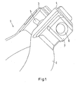
- a clamping element 1 which is designed as a profile clamp, that is generally as a clamp is.
- the clamping element 1 has a clamp band 2, which is provided at its ends with clamping heads 3, 4.
- a clamping screw 5 is provided, which cooperates with a threaded nut 6.
- the threaded nut 6 is held against rotation in a spring clip 7 which is latched to the clamping head 4 with the clamping element 1.
- the threaded nut 6 is formed as a square nut. But it is also conceivable to use, for example, a hex nut.
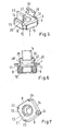
- the embodiment of the spring clip 7 according to a first embodiment is in Fig. 2 shown.
- the spring clip 7 is formed substantially U-shaped with two legs 8, 9 and a bottom 10.
- On an inner side of the bottom 10 is the threaded nut 6, which is again designed as a square nut.
- the legs 8, 9 have an inwardly directed first stage 11, 12, wherein the threaded nut 6 is held between the respective first stage 11, 12 and the bottom 10.
- the legs 8, 9 are at the same time on the side of the threaded nut 6, so that already thereby takes place against rotation.
- retaining tabs 13, 14 are provided, which extend from the bottom 10 and are bent upwards vertically, so that thereby takes place a further rotation of the threaded nut 6.
- the threaded nut is thus form-fitting in a plane perpendicular to a screwing-in direction of the clamping screw 5 held.
- the threaded nut 6 is thus held captive in the spring clip 7.
- the legs 8, 9 each have a second step 16, 17, which is directed outwards.
- a locking groove 18, 19 is formed.
- the spring clip 7 is inserted into a corresponding opening 20 in the clamping head 4 and locked there in such a way that edges of the opening 20 in the region of the locking grooves 18, 19 are positioned.
- a distance between the first stage 11, 12 and the second stage 16, 17 is greater than a material thickness of the clamping head 4, so that a pivoting of the spring clip 7 in a desired range is possible. This makes it possible to align the threaded nut 6 with respect to the clamping screw 5 angularly.
- the bottom 10 of the spring clip 7 is provided with a central opening 21 through which the clamping screw 5 can be passed.
- the adjustment of the clamping screw is thus not limited by the spring clip 7.
- the legs 8, 9 each have at least one thread on its inner side, which cooperates with the clamping screw 5.
- a pre-assembly of the clamping screw 5 is possible.
- the inner side of the legs 8, 9 smoothly form, in which case through the inside a sliding guide of the clamping screw 5 can be made so that an insertion of the clamping screw 5 in the threaded nut 6 is relatively easy.
- Fig. 4 is the spring clip 7 with the threaded nut 6 shown again in a spatial representation, but from a different perspective than in Fig. 2 , It can be seen that edges 22, 23, 24, 25 of the spring clip 7 are formed as open edges, protrude through the corners or edges of the threaded nut 6. Thereby, the spring clip 7 can be manufactured with relatively high tolerances, which allows a simple production by means of bending process.
- the legs 8, 9 and the retaining tabs 13, 14 are formed integrally with the bottom 10.
- Fig. 5 shows a spring clip 7 of a second embodiment, wherein like parts are provided with corresponding reference numerals.
- the spring clip 7 according to the embodiment of Fig. 2 to 4 has the spring clip 7 in Fig. 5 two legs 8, 9, which emanate from a bottom 10, so that the spring clip 7 is formed substantially U-shaped.
- retaining tabs 13, 14 are provided.
- the legs 8, 9 have an inwardly directed first stage 11, 12, wherein the threaded nut 6 between the first stage 11, 12 and the bottom 10 and between the legs 8, 9 and the retaining tabs 13, 14 is held positively and captive ,
- the legs 8, 9 are provided with inwardly directed securing tabs 26, 27, 28, 28 ', which serve for locking the spring clip 7 in the clamping element 1 or in a clamping head 4. Free ends 29, 30 of the legs 8, 9 are bent towards each other and designed such that they can be brought into engagement with a thread of the clamping screw. This allows a relatively simple pre-positioning of the clamping screw done.
- Fig. 7 now shows the spring clip 7 according to the FIGS. 6 and 5 again in a spatial representation, but from a different perspective. Also, the spring clip 7 of this embodiment has open edges 22, 23, 24, 25.
- securing tabs can also in the embodiment according to the Fig. 2 to 4 be used.
- threaded nut 6 for example, as a hex nut according to further retaining tabs may be provided, wherein edges between the retaining tabs may be formed correspondingly open.
- the inventive design of the clamping element with the spring clip 7 commercially available threaded nuts, such as square or hex nuts can be used. These threaded nuts are encased in the spring clip against rotation, so positive and captive held. Due to the design of the spring clip with the legs of the spring clip can be clipped, for example, in the chuck of a profile clamp or other clamp. In this case, even a corresponding pivoting behavior of the spring clip can be achieved, so that a relatively simple assembly, in particular a simple insertion of the clamping screw in the threaded nut, is possible. It is also possible without much effort to provide a guide of the clamping screw before it is brought into engagement with the threaded nut. It can already be done a pre-engagement of the clamping screw. This makes a simple pre-assembly possible. Since only one locking connection takes place between spring clip and clamping element, a variety of materials can be combined. In particular, it is not necessary to make the spring clip of the same material as the clamping element.
Description
- Die Erfindung betrifft eine Spannschelle, mit einer Spannschraube, die mit einer mehreckigen Gewindemutter zusammenwirkt.
- Derartige Spannelemente dienen beispielsweise dazu, Rohre oder Leitungen auf Anschlussstutzen durch das Einbringen radialer Spannkräfte zu halten. Dabei werden die Spannelemente durch Anziehen der Spannschraube zusammengezogen, wobei die Spannschraube in die Gewindemutter hineingeschraubt wird.
- Bei Spannschellen, wie beispielsweise Profilschellen, werden die Gewindemutter und die Spannschraube an jeweils einem Spannkopf der Schelle gelagert. Da sich beim Anziehen der Spannschraube der Radius der Spannschelle verringert, verändert sich die Winkellage zwischen Gewindemutter und- Spannschraube. Dadurch steigen die erforderlichen Betätigungskräfte an.
- Es ist nun bekannt, die Gewindemutter und/oder die Spannschraube schwenkbar zu lagern. Eine derartige Lagerung ist jedoch relativ aufwendig und damit kostenintensiv.
- In
US 2 002 141 A wird eine Spannschelle mit einer Spannschraube und einer Gewindemutter offenbart. Die Schraube wird dabei durch einen gebogenen Abschnitt des Schellenbandes geführt. Die Schraube greift dann durch Öffnungen von mit dem Schellenband verbundenen Teilen. Die Gewindemutter ist dabei an der der Spannschraube abgewandten Seite des Teils angeordnet. D1 offenbart dabei weder, dass die Gewindemutter verdrehsicher in einem Federbügel gehalten ist, noch dass ein Federbügel mit dem Spannelement verrastet wäre. Dementsprechend werden auch keinerlei Schenkel eines Federbügels gezeigt, oder dass Enden solcher Schenkel mit einem Gewinde der Spannschraube in Eingriff bringbar wären. -
DE 19 01 917 U betrifft eine Spannschelle für Schläuche und Rohre und offenbart den Oberbegriff von Anspruch 1. Die Spannschelle weist dabei Spannkörper in Kastenform auf. Durch Öffnungen in den Spannkörpern ist dabei eine Spannschraube geführt, die in eine Gewindemutter eingreift. -
EP 2 177 775 A1 offenbart eine Anlage zum Zusammenbau von zwei Teilen. Die Anlage umfasst dabei eine Spannschraube, sowie eine Gewindemutter. Die Gewindemutter wird dabei verdrehsicher zwischen zwei Schenkeln eines Federbügels gehalten. -
US 2 695 046 A offenbart eine Gewindemutter und eine Spannschraube. Die Gewindemutter wird dabei in einem Federbügel verdrehsicher gehalten. Der Federbügel umfasst dabei zwei Schenkel. - Auch in
BE 499 584 A -
DE 101 22 647 C1 offenbart eine Rohrschelle, umfassend ein Schellenband und zwei Spannbacken. Die Spannbacken können dabei mit einer Spannschraube und einer Gewindemutter aufeinander zu bewegt werden, um die Rohrschelle zu spannen. Die Gewindemutter wird dabei durch radial vorstehende Laschen verdrehsicher gehalten. -
US 2 571 747 A zeigt ein Befestigungsbauteil zur Aufnahme und Befestigung eines Schraubbolzens. Das Befestigungsbauteil wird zunächst in eine Öffnung eines Trägers eingeführt, bis Vorsprünge an einer Stirnseite des Trägers anliegen. Gleichzeitig verrasten Zungen an der den Vorsprüngen gegenüberliegenden Stirnseite des Trägers. - Aus
US 2 627 294 A ist eine Käfigmutter bekannt. Die Käfigmutter umfasst eine Halterung, mit der eine Mutter an einer Öffnung eines Trägers vorbefestigt werden kann. Die Halterung umfasst hierfür U-förmig gebogene Vorsprünge, die den Träger formschlüssig im Bereich der Öffnung von beiden Stirnseiten umgreifen. - Der Erfindung liegt nun die Aufgabe zugrunde, die Lagerung der Gewindemutter am Spannelement einfach zu gestalten.
- Efindungsgemäß wird diese Aufgabe durch eine Spannschelle nach den Kennzeichen von Anspruch 1 gelöst.
- Die Herstellung eines Federbügels kann relativ einfach durch Umformen eines entsprechenden Materialstreifens, beispielsweise aus Metall oder ähnlichem, erfolgen. Dabei kann durch die Verwendung des Federbügels eine relativ spielfreie Lagerung erhalten werden, die gleichzeitig beim Einwirken von äußeren Kräften etwas nachgiebig ist, so dass ohne Probleme ein Winkelausgleich zwischen Gewindemutter und Spannschraube erfolgen kann. Dabei kann der Federbügel aus einem anderen Material hergestellt sein als das Spannelement und die Gewindemutter. Die Rastverbindung zwischen Federbügel und Spannelement lässt nahezu beliebige Materialkombinationen zu.
- Erfindungsgemäß ist der Federbügel im Wesentlichen U-förmig ausgebildet und weist einen Boden und zwei Schenkel auf. Eine derartige Ausbildung des Federbügels ist relativ einfach herstellbar. Durch die beiden Schenkel erfolgt dabei eine Verdrehsicherung der Gewindemutter, die mit einer Stirnseite am Boden anliegen kann. Gleichzeitig wird der Federbügel über die Schenkel am Spannelement gehalten. Dabei können die Schenkel beispielsweise eine federnde Haltekraft erzeugen.
- Erfindungsgemäß weisen die Schenkel jeweils eine nach innen gerichtete erste Stufe auf, wobei die Gewindemutter zwischen Boden und der ersten Stufe gehalten ist. Die Gewindemutter ist also formschlüssig im Federbügel gehalten. Die beim Einschrauben der Schraube in die Gewindemutter auftretenden Kräfte werden vom Federbügel aufgenommen. Dabei kann erfindungsgemäß ein leichtes Verschwenken zwischen dem Federbügel und dem Spannelement möglich sein. Dies dient zur Erleichterung beim Einfädeln der Gewindeschraube während der Montage.
- Vorzugsweise gehen vom Boden mindestens zwei Haltelaschen an jeweils einer Seite aus, die die Gewindemutter seitlich halten. Die Gewindemutter kann dann auch in einer Richtung, die quer zur Einschraubrichtung verläuft, nicht vom Federhalter getrennt werden. Vielmehr ist die Gewindemutter sozusagen in den Federbügel eingeformt oder eingekammert und unverlierbar gehalten. Dabei können die Haltelaschen zusätzlich zu den Schenkeln ein möglicherweise auftretendes Drehmoment aufnehmen. Sie dienen also ebenfalls als Verdrehsicherung der Gewindemutter. Dadurch können höhere Drehmomente aufgenommen werden.
- Vorteilhafterweise weisen die Schenkel jeweils eine nach außen gerichtete zweite Stufe auf, wobei zwischen der ersten Stufe und der zweiten Stufe an einer Außenseite der Schenkel eine Rastnut ausgebildet ist. Diese Rastnut wirkt mit einem entsprechend ausgebildeten Rand einer Öffnung des Spannelements zusammen, so dass der Federbügel und damit die Gewindemutter verliersicher am Spannelement gehalten ist. Dabei kann die Rastnut eine derartige Erstreckung aufweisen, dass ein Schwenkverhalten des Federbügels mit der Gewindemutter zugelassen wird. Der Federbügel ist dann schwenkbar mit dem Spannelement verrastet.
- Dabei ist besonders bevorzugt, dass an einer Innenseite der Schenkel im Bereich der Rastnut mindestens ein Gewindegang eingeformt ist. Dieser Gewindegang kann relativ einfach ausgebildet sein, beispielsweise als umgeformtes Blech. Ein derartiger Gewindegang dient zum Vormontieren der Spannschraube. Dadurch wird das Einführen der Spannschraube in die Gewindemutter vereinfacht. Bereits vor Montage des Spannelements kann die Spannschraube dann in den Gewindegang im Bereich der Rastnut eingeführt werden und ist damit verliersicher gehalten.
- In einer anderen bevorzugten Ausführungsform sind freie Enden der Schenkel aufeinander zu gebogen, wobei gegebenenfalls die Enden mit einem Gewinde der Spannschraube in Eingriff bringbar sind. Die freien Enden können dafür entsprechend ausgebildet sein, also beispielsweise abgeflacht sein und/oder mit einer Rundung versehen sein. Durch die eingebogenen freien Enden der Schenkel kann eine Führung der Spannschraube erfolgen, so dass diese leichter in die Gewindemutter eingeführt werden kann. Wenn nun die Enden mit einem Gewinde der Spannschraube in Eingriff bringbar sind, kann eine verliersichere Vorpositionierung der Spannschraube erfolgen. Dabei sind keine zusätzlichen Bauteile erforderlich. Vielmehr erfolgt die Vorpositionierung mit sehr einfachen, bereits vorhandenen Mitteln.
- Vorzugsweise sind an den Schenkeln Sicherungslaschen vorgesehen, die insbesondere einstückig mit den Schenkeln ausgebildet sind. Die Sicherungslaschen dienen zum Verrasten des Federbügels mit dem Spannelement und verhindern so ein unbeabsichtigtes Herausfallen des Federbügels. Bei einer einstückigen Ausführung lassen sich die Sicherungslaschen durch einfaches Ausstanzen und Umbiegen erzeugen. Der Herstellungsaufwand bleibt also gering. Dabei kann durch die Wahl einer entsprechenden Wandstärke des Federbügels eine ausreichende Elastizität der Sicherungslaschen gewährleistet werden, so dass eine problemlose Montage gewährleistet ist.
- Vorzugsweise sind zwischen Haltelaschen und Schenkeln offene Kanten ausgebildet. Derartig offene Kanten erleichtern zum einen den Umformvorgang zur Herstellung des Federbügels, zum anderen ermöglichen sie die Herstellung mit relativ großen Toleranzen, da Kanten der Gewindemutter einfach im Bereich der offenen Kanten des Federbügels positioniert werden, wodurch unnötiger Zwang vermieden wird.
- Die Erfindung wird im Folgenden anhand bevorzugter Ausführungsbeispiele in Verbindung mit der Zeichnung beschrieben. Hierin zeigen:
- Fig. 1
- ein Spannelement,
- Fig. 2.
- einen Federbügel einer ersten Ausführungsform in dreidimensionaler Ansicht,
- Fig. 3
- den Federbügel gemäß
Fig. 2 in Schnittansicht, - Fig. 4
- den Federbügel aus
Fig. 2 und 3 aus einer anderen Blickrichtung, - Fig. 5
- einen Federbügel einer zweiten Ausführungsform in dreidimensionaler Darstellung,
- Fig. 6
- den Federbügel nach
Fig. 5 in geschnittener Darstellung und - Fig. 7
- den Federbügel nach den
Fig. 5 und 6 aus einer anderen Blickrichtung. - In
Fig. 1 ist ein Spannelement 1 gezeigt, das als Profilschelle, also allgemein als Spannschelle, ausgebildet ist. Das Spannelement 1 weist ein Schellenband 2 auf, das an seinen Enden mit Spannköpfen 3, 4 versehen ist. Zum Spannen der Profilschelle ist eine Spannschraube 5 vorgesehen, die mit einer Gewindemutter 6 zusammenwirkt. Die Gewindemutter 6 ist verdrehsicher in einem Federbügel 7 gehalten, der am Spannkopf 4 mit dem Spannelement 1 verrastet ist. - Bei diesem Beispiel ist die Gewindemutter 6 als Vierkantmutter ausgebildet. Es ist aber auch denkbar, beispielsweise eine Sechskantmutter zu verwenden.
- Die Ausgestaltung des Federbügels 7 gemäß einer ersten Ausführungsform ist in
Fig. 2 dargestellt. Der Federbügel 7 ist im Wesentlichen U-förmig mit zwei Schenkeln 8, 9 und einem Boden 10 ausgebildet. An einer Innenseite des Bodens 10 liegt die Gewindemutter 6 an, die wieder als Vierkantmutter ausgebildet ist. Die Schenkel 8, 9 weisen eine nach innen gerichtete erste Stufe 11, 12 auf, wobei die Gewindemutter 6 zwischen der jeweils ersten Stufe 11, 12 und dem Boden 10 gehalten ist. Die Schenkel 8, 9 liegen gleichzeitig seitlich an der Gewindemutter 6 an, so dass bereits dadurch eine Verdrehsicherung erfolgt. - Zusätzlich sind Haltelaschen 13, 14 vorgesehen, die vom Boden 10 ausgehen und senkrecht nach oben umgebogen sind, so dass dadurch eine weitere Verdrehsicherung der Gewindemutter 6 erfolgt. Gleichzeitig ist die Gewindemutter damit in einer Ebene senkrecht zu einer Einschraubrichtung der Spannschraube 5 formschlüssig gehalten. Die Gewindemutter 6 ist also unverlierbar im Federbügel 7 gehalten.
- Die Schenkel 8, 9 weisen jeweils eine zweite Stufe 16, 17 auf, die nach außen gerichtet ist. Dabei ist jeweils zwischen der ersten Stufe 11, 12 und der zweiten Stufe 16, 17 eine Rastnut 18, 19 ausgebildet.
- Wie aus
Fig. 3 zu erkennen ist, ist der Federbügel 7 in einer entsprechenden Öffnung 20 im Spannkopf 4 eingeführt und dort derartig verrastet, dass Ränder der Öffnung 20 im Bereich der Rastnuten 18, 19 positioniert sind. Dabei ist ein Abstand zwischen der ersten Stufe 11, 12 und der zweiten Stufe 16, 17 größer als eine Materialstärke des Spannkopfs 4, so dass ein Verschwenken des Federbügels 7 in einem gewünschten Bereich möglich ist. Dadurch ist es möglich, die Gewindemutter 6 bezüglich der Spannschraube 5 winkelmäßig auszurichten. - Der Boden 10 des Federbügels 7 ist mit einer zentralen Öffnung 21 versehen, durch die die Spannschraube 5 hindurchgeführt werden kann. Der Verstellweg der Spannschraube wird durch den Federbügel 7 also nicht beschränkt.
- Im Bereich der Rastnuten 18, 19 können die Schenkel 8, 9 an ihrer Innenseite jeweils mindestens einen Gewindegang aufweisen, der mit der Spannschraube 5 zusammenwirkt. Dadurch ist eine Vormontage der Spannschraube 5 möglich. Es ist auch denkbar, die Innenseite der Schenkel 8, 9 glatt auszubilden, wobei dann durch die Innenseite eine Gleitführung der Spannschraube 5 erfolgen kann, so dass ein Einführen der Spannschraube 5 in die Gewindemutter 6 relativ einfach möglich ist.
- In
Fig. 4 ist der Federbügel 7 mit der Gewindemutter 6 wieder in räumlicher Darstellung gezeigt, aber aus einer anderen Perspektive als inFig. 2 . Es ist zu erkennen, dass Kanten 22, 23, 24, 25 des Federbügels 7 als offene Kanten ausgebildet sind, durch die Ecken bzw. Kanten der Gewindemutter 6 herausragen. Dadurch kann der Federbügel 7 mit relativ hohen Toleranzen gefertigt werden, was eine einfache Herstellung mittels Biegeprozess ermöglicht. - Die Schenkel 8, 9 und die Haltelaschen 13, 14 sind dabei einstückig mit dem Boden 10 ausgebildet.
-
Fig. 5 zeigt einen Federbügel 7 einer zweiten Ausführungsform, wobei gleiche Teile mit entsprechenden Bezugszeichen versehen sind. Wie auch der Federbügel 7 gemäß der Ausgestaltung derFig. 2 bis 4 weist der Federbügel 7 inFig. 5 zwei Schenkel 8, 9 auf, die von einem Boden 10 ausgehen, so dass der Federbügel 7 im Wesentlichen U-förmig ausgebildet ist. Zusätzlich sind Haltelaschen 13, 14 vorgesehen. Die Schenkel 8, 9 weisen eine nach innen gerichtete erste Stufe 11, 12 auf, wobei die Gewindemutter 6 zwischen der ersten Stufe 11, 12 und dem Boden 10 sowie zwischen den Schenkeln 8, 9 und den Haltelaschen 13, 14 formschlüssig und verliersicher gehalten ist. - Die Schenkel 8, 9 sind mit nach innen gerichteten Sicherungslaschen 26, 27, 28, 28' versehen, die zum Verrasten des Federbügels 7 im Spannelement 1 bzw. in einem Spannkopf 4 dienen. Freie Enden 29, 30 der Schenkel 8, 9 sind aufeinander zu gebogen und derart ausgebildet, dass sie mit einem Gewinde der Spannschraube in Eingriff bringbar sind. Dadurch kann ein relativ einfaches Vorpositionieren der Spannschraube erfolgen.
- Dies ist in
Fig. 6 dargestellt. -
Fig. 7 zeigt nun den Federbügel 7 gemäß derFig. 6 und 5 wieder in räumlicher Darstellung, aber aus einer anderen Perspektive. Auch der Federbügel 7 dieser Ausgestaltung weist offene Kanten 22, 23, 24, 25 auf. - Die bei der Ausführungsform gemäß der
Fig. 5 bis 7 gezeigten Sicherungslaschen können auch bei der Ausführungsform gemäß derFig. 2 bis 4 eingesetzt werden. - Bei einer Ausbildung der Gewindemutter 6 beispielsweise als Sechskantmutter können entsprechend weitere Haltelaschen vorgesehen sein, wobei Kanten zwischen den Haltelaschen entsprechenderweise offen ausgebildet sein können.
- Durch die erfindungsgemäße Ausgestaltung des Spannelements mit dem Federbügel 7 können handelsübliche Gewindemuttern, wie Vierkant- oder Sechskantmuttern, verwendet werden. Diese Gewindemuttern werden im Federbügel verdrehsicher eingekammert, also formschlüssig und verliersicher gehalten. Durch die Ausgestaltung der Federbügel mit den Schenkeln kann der Federbügel beispielsweise im Spannkopf einer Profilschelle oder einer anderen Spannschelle eingeklipst werden. Dabei kann sogar ein entsprechendes Schwenkverhalten des Federbügels erreicht werden, so dass eine relativ einfache Montage, insbesondere ein einfaches Einführen der Spannschraube in die Gewindemutter, möglich ist. Auch ist es ohne großen Aufwand möglich, eine Führung der Spannschraube bereitzustellen, bevor diese mit der Gewindemutter in Eingriff gebracht wird. Dabei kann bereits ein Voreinrasten der Spannschraube erfolgen. Dadurch ist eine einfache Vormontage möglich. Da zwischen Federbügel und Spannelement nur eine Rastverbindung erfolgt, können vielfältige Materialien miteinander kombiniert werden. Es ist insbesondere nicht erforderlich, den Federbügel aus dem gleichen Material herzustellen wie das Spannelement.
- Insgesamt wird eine relativ einfache Lagerung der Gewindemutter am Spannelement ermöglicht, die gleichzeitig eine gewisse Verschwenkbarkeit zulässt, so dass ein einfaches Einfädeln der Spannschraube gewährleistet ist.
Claims (7)
- Spannschelle mit einer Spannschraube, die mit einer mehreckigen Gewindemutter zusammenwirkt, wobei die Gewindemutter (6) verdrehsicher in einem Federbügel (7) gehalten ist, der mit der Spannschelle (1) verrastet ist, und wobei der Federbügel (7) im Wesentlichen U-förmig ausgebildet ist und einen Boden (10) und zwei Schenkel (8, 9) aufweist, dadurch gekennzeichnet, dass die Schenkel (8, 9) jeweils eine nach innen gerichtete erste Stufe (11, 12) aufweisen, wobei die Gewindemutter (6) zwischen Boden (10) und der ersten Stufe (11, 12) gehalten ist, und wobei ein Verschwenken zwischen dem Federbügel (7) und der Spannschelle (1) möglich ist.
- Spannschelle nach Anspruch 1, dadurch gekennzeichnet, dass vom Boden (10) mindestens zwei Haltelaschen (14, 15) an jeweils einer Seite ausgehen, die die Gewindemutter (6) seitlich halten.
- Spannschelle nach Anspruch 1 oder 2, dadurch gekennzeichnet, dass die Schenkel (8, 9) jeweils eine nach außen gerichtete zweite Stufe (16, 17) aufweisen, wobei zwischen der ersten Stufe (11, 12) und der zweiten Stufe (16, 17) an einer Außenseite der Schenkel (8, 9) eine Rastnut (18, 19) ausgebildet ist.
- Spannschelle nach Anspruch 3, dadurch gekennzeichnet, dass an einer Innenseite der Schenkel (8, 9) im Bereich der Rastnuten (18, 19) mindestens ein Gewindegang eingeformt ist.
- Spannschelle nach Ansprüche 1 bis 2, dadurch gekennzeichnet, dass freie Enden (29, 30) der Schenkel (8, 9) aufeinander zu gebogen sind, wobei die freien Enden (29, 30) mit einem Gewinde der Spannschraube (5) in Eingriff bringbar sind.
- Spannschelle nach einem der Ansprüche 2 bis 5, dadurch gekennzeichnet, dass an den Schenkeln (8, 9) Sicherungslaschen (26, 27, 28, 28') vorgesehen sind, die insbesondere einstückig mit den Schenkeln (8, 9) ausgebildet sind.
- Spannschelle nach einem der Ansprüche 2 bis 6, dadurch gekennzeichnet, dass zwischen Haltelaschen (14, 15) und den Schenkeln (8, 9) offene Kanten (22, 23, 24, 25) ausgebildet sind.
Applications Claiming Priority (1)
| Application Number | Priority Date | Filing Date | Title |
|---|---|---|---|
| DE102011009536A DE102011009536B4 (de) | 2011-01-27 | 2011-01-27 | Spannschelle |
Publications (2)
| Publication Number | Publication Date |
|---|---|
| EP2481939A1 EP2481939A1 (de) | 2012-08-01 |
| EP2481939B1 true EP2481939B1 (de) | 2015-07-01 |
Family
ID=45098774
Family Applications (1)
| Application Number | Title | Priority Date | Filing Date |
|---|---|---|---|
| EP11008901.8A Active EP2481939B1 (de) | 2011-01-27 | 2011-11-09 | Spannschelle |
Country Status (9)
| Country | Link |
|---|---|
| US (1) | US8978212B2 (de) |
| EP (1) | EP2481939B1 (de) |
| JP (1) | JP5484492B2 (de) |
| KR (1) | KR101450161B1 (de) |
| CN (1) | CN102620070B (de) |
| DE (1) | DE102011009536B4 (de) |
| ES (1) | ES2545985T3 (de) |
| RS (1) | RS54222B1 (de) |
| RU (1) | RU2487285C1 (de) |
Families Citing this family (11)
| Publication number | Priority date | Publication date | Assignee | Title |
|---|---|---|---|---|
| JP5632941B1 (ja) * | 2013-07-29 | 2014-11-26 | 株式会社淀川製鋼所 | 締結具取付装置及び締結具取付構造 |
| EP3051977B1 (de) * | 2013-10-01 | 2018-11-07 | SPG International LLC | Regalsystem |
| DE102013219957A1 (de) | 2013-10-01 | 2015-04-16 | Bayerische Motoren Werke Aktiengesellschaft | Verfahren zum Befestigen eines ersten Bauteils an einem zweiten Bauteil eines Kraftwagens sowie Befestigungsanordnung eines ersten Bauteils an einem zweiten Bauteil eines Kraftwagens |
| GB2528094B (en) * | 2014-07-09 | 2017-04-26 | Jaguar Land Rover Ltd | Improved fastening device |
| DE102016123388B4 (de) * | 2016-12-02 | 2019-01-10 | Norma Germany Gmbh | Profilschelle |
| CN107893808B (zh) * | 2017-12-17 | 2023-05-16 | 无锡优耐特能源科技有限公司 | 一种浮动螺母 |
| CN109227594B (zh) * | 2018-09-19 | 2023-10-03 | 广东工业大学 | 一种卡环式机器人连接组件 |
| DE102018131671A1 (de) | 2018-12-11 | 2020-06-18 | Ihi Charging Systems International Gmbh | Spannschelle und Abgasturbolader mit einer solchen Spannschelle |
| DE102019118166A1 (de) * | 2019-07-04 | 2021-01-07 | Volkswagen Aktiengesellschaft | Schelle |
| CN114086810B (zh) * | 2021-10-18 | 2023-10-24 | 浙江德宝通讯科技股份有限公司 | 一种通信塔 |
| DE202022101207U1 (de) | 2022-03-04 | 2022-03-16 | Norma Germany Gmbh | Federbügel zur verdrehsicheren Aufnahme einer Gewindemutter sowie Gewindemutteranordnung und Spannschelle aufweisend einen derartigen Federbügel |
Citations (1)
| Publication number | Priority date | Publication date | Assignee | Title |
|---|---|---|---|---|
| US2627294A (en) * | 1950-05-05 | 1953-02-03 | United Carr Fastener Corp | Cage nut |
Family Cites Families (28)
| Publication number | Priority date | Publication date | Assignee | Title |
|---|---|---|---|---|
| BE499584A (de) * | ||||
| US2002141A (en) * | 1933-12-15 | 1935-05-21 | William C Dumke | Clamp |
| US2409128A (en) * | 1944-02-25 | 1946-10-08 | Rudolf G Krasberg | Banding means |
| US2571747A (en) * | 1948-12-10 | 1951-10-16 | United Carr Fastener Corp | Bolt fastener |
| US2695046A (en) * | 1952-08-25 | 1954-11-23 | Tinuerman Products Inc | Cage nut having auxiliary spring locking tongues |
| US2787039A (en) * | 1953-03-16 | 1957-04-02 | Rudolf G Krasberg | Hose clamp |
| DE1901917U (de) * | 1964-04-30 | 1964-10-08 | Hans Sen Kreidel | Spannschelle fuer schlaeuche und rohre. |
| FR2000273A1 (de) | 1968-01-16 | 1969-09-05 | Sumitomo Chemical Co | |
| JPS5139093Y2 (de) * | 1972-03-12 | 1976-09-24 | ||
| JPS48103756A (de) | 1972-04-14 | 1973-12-26 | ||
| DE2321618A1 (de) | 1973-04-28 | 1974-11-14 | Krauss Maffei Ag | Elektromagnet, insbesondere zum tragen oder zum tragen und fuehren eines schwebefahrzeugs |
| JPS5013876U (de) * | 1973-06-06 | 1975-02-13 | ||
| DE3226124C2 (de) | 1982-07-13 | 1984-09-20 | Minnesota Mining And Manufacturing Co., Saint Paul, Minn. | Gummielastische Umhüllung für elektrische Kabel und dergleichen |
| SU1622705A1 (ru) * | 1987-02-26 | 1991-01-23 | И.Т. Журавель | Петлевой зажим дл закреплени гибких шлангов на патрубках, штуцерах |
| NL8900619A (nl) * | 1989-03-14 | 1990-10-01 | Walraven J Van Bv | Buisklem. |
| CH678501A5 (de) | 1989-05-16 | 1991-09-30 | Elpatronic Ag | |
| JPH034630A (ja) | 1989-06-01 | 1991-01-10 | Mitsubishi Electric Corp | Fmステレオ受信機 |
| FR2699236B1 (fr) * | 1992-12-11 | 1995-02-24 | Rapid Sa | Ecrou encagé perfectionné. |
| JPH08103756A (ja) * | 1994-10-04 | 1996-04-23 | Mitsubishi Materials Corp | 生ゴミ処理機 |
| FR2725773B1 (fr) | 1994-10-13 | 1996-11-29 | Vallourec Oil & Gas | Assemblage filete pour tubes |
| JP3013240U (ja) * | 1994-12-28 | 1995-07-11 | 利正 佐藤 | ジョイント金具 |
| US5961161A (en) * | 1998-03-13 | 1999-10-05 | Mage Ag | Pipe connector clamp |
| KR100318038B1 (ko) * | 1999-09-07 | 2001-12-22 | 안중기 | 수로용 관의 연결장치 |
| DE10215647A1 (de) * | 2001-04-10 | 2002-12-05 | Edgar Emil Sinn | Rohrschelle |
| DE10122647C1 (de) | 2001-05-10 | 2002-04-18 | Rasmussen Gmbh | Rohrschelle, insbesondere Rohrkupplung |
| JP3739342B2 (ja) * | 2002-08-06 | 2006-01-25 | 株式会社アカギ | 配管用吊りバンド |
| DE20317300U1 (de) * | 2003-11-07 | 2004-01-08 | Wilhelm Ungeheuer Söhne GmbH | Klapprohrschelle |
| FR2937387A1 (fr) * | 2008-10-16 | 2010-04-23 | Lisi Automotive Rapid | Agencement d'assemblage de deux pieces, telles que deux panneaux a l'aide d'un dispositif a ecrou a cage |
-
2011
- 2011-01-27 DE DE102011009536A patent/DE102011009536B4/de not_active Expired - Fee Related
- 2011-11-09 ES ES11008901.8T patent/ES2545985T3/es active Active
- 2011-11-09 RS RS20150602A patent/RS54222B1/en unknown
- 2011-11-09 EP EP11008901.8A patent/EP2481939B1/de active Active
- 2011-12-27 CN CN201110443179.4A patent/CN102620070B/zh active Active
-
2012
- 2012-01-09 US US13/346,279 patent/US8978212B2/en active Active
- 2012-01-18 RU RU2012101501/06A patent/RU2487285C1/ru not_active IP Right Cessation
- 2012-01-19 JP JP2012008777A patent/JP5484492B2/ja not_active Expired - Fee Related
- 2012-01-25 KR KR1020120007251A patent/KR101450161B1/ko active IP Right Grant
Patent Citations (1)
| Publication number | Priority date | Publication date | Assignee | Title |
|---|---|---|---|---|
| US2627294A (en) * | 1950-05-05 | 1953-02-03 | United Carr Fastener Corp | Cage nut |
Also Published As
| Publication number | Publication date |
|---|---|
| JP2012154485A (ja) | 2012-08-16 |
| DE102011009536B4 (de) | 2013-09-19 |
| CN102620070B (zh) | 2015-04-08 |
| JP5484492B2 (ja) | 2014-05-07 |
| US8978212B2 (en) | 2015-03-17 |
| KR20120087085A (ko) | 2012-08-06 |
| RS54222B1 (en) | 2015-12-31 |
| ES2545985T3 (es) | 2015-09-17 |
| EP2481939A1 (de) | 2012-08-01 |
| RU2487285C1 (ru) | 2013-07-10 |
| CN102620070A (zh) | 2012-08-01 |
| DE102011009536A1 (de) | 2012-08-02 |
| KR101450161B1 (ko) | 2014-10-13 |
| US20120192387A1 (en) | 2012-08-02 |
Similar Documents
| Publication | Publication Date | Title |
|---|---|---|
| EP2481939B1 (de) | Spannschelle | |
| EP3009694B1 (de) | Befestigungselement und baugruppe aus befestigungselement und aufnahmeelement | |
| EP2184029B1 (de) | Dehnschraube zur Zahnregulierung | |
| WO2012048686A1 (de) | Käfigmutter | |
| EP3423742B1 (de) | Profilschelle | |
| EP1828623B1 (de) | Vorrichtung zum befestigen eines anbauteils und eines trägerteiles in einem abstand voneinander | |
| DE10357844B4 (de) | Befestigungssystem | |
| EP2218923A2 (de) | Befestigungsvorrichtung zur Anordnung eines Stangenelementes an einer Montageschiene | |
| DE102005000129A1 (de) | Befestigungsvorrichtung für die Befestigung von Solarpaneelen an einer Montageschiene | |
| DE19828059A1 (de) | Anschlußarmatur mit einem durch Schlitze in Haltezungen aufgeteilten Befestigungsvorsprung | |
| EP2500587A1 (de) | Befestigungsvorrichtung zur Anordnung an einer Montageschiene | |
| DE102012221228A1 (de) | Toleranzausgleichsvorrichtung | |
| DE102014103535A1 (de) | Vorrichtung zur Befestigung eines Bauteils an einem Trägerbauteil | |
| DE102009000786A1 (de) | Befestigungsvorrichtung zur Anordnung an einer Montageschiene | |
| EP1775482B1 (de) | Schnellbefestigungselement | |
| DE102007015129B3 (de) | Nicht demontierbarer Clip aus Kunststoff | |
| DE102010018471A1 (de) | Schraubverbindungsvorrichtung zur Herstellung einer toleranzausgleichenden Schraubverbindung | |
| DE102009000702B4 (de) | Befestigungsvorrichtung zur Anordnung an einer Montageschiene | |
| DE102017221802A1 (de) | Befestigungsklemme und Profilstabsystem | |
| EP3626898B1 (de) | Profilrohrsystem | |
| DE10215647A1 (de) | Rohrschelle | |
| DE102011112049B4 (de) | Gurtschlossbaugruppe | |
| WO2011144339A1 (de) | Montagesystem für verschraubungen | |
| DE102004032053A1 (de) | Rohrschelle mit integriertem Rast-Verschluss | |
| EP3045743A1 (de) | Tragstrukturhalterung für einen fluidverteiler, montageanordnung und verfahren zur montage eines fluidverteilers |
Legal Events
| Date | Code | Title | Description |
|---|---|---|---|
| PUAI | Public reference made under article 153(3) epc to a published international application that has entered the european phase |
Free format text: ORIGINAL CODE: 0009012 |
|
| AK | Designated contracting states |
Kind code of ref document: A1 Designated state(s): AL AT BE BG CH CY CZ DE DK EE ES FI FR GB GR HR HU IE IS IT LI LT LU LV MC MK MT NL NO PL PT RO RS SE SI SK SM TR |
|
| AX | Request for extension of the european patent |
Extension state: BA ME |
|
| 17P | Request for examination filed |
Effective date: 20121113 |
|
| 17Q | First examination report despatched |
Effective date: 20140204 |
|
| GRAP | Despatch of communication of intention to grant a patent |
Free format text: ORIGINAL CODE: EPIDOSNIGR1 |
|
| INTG | Intention to grant announced |
Effective date: 20150219 |
|
| GRAS | Grant fee paid |
Free format text: ORIGINAL CODE: EPIDOSNIGR3 |
|
| GRAA | (expected) grant |
Free format text: ORIGINAL CODE: 0009210 |
|
| AK | Designated contracting states |
Kind code of ref document: B1 Designated state(s): AL AT BE BG CH CY CZ DE DK EE ES FI FR GB GR HR HU IE IS IT LI LT LU LV MC MK MT NL NO PL PT RO RS SE SI SK SM TR |
|
| REG | Reference to a national code |
Ref country code: GB Ref legal event code: FG4D Free format text: NOT ENGLISH |
|
| REG | Reference to a national code |
Ref country code: AT Ref legal event code: REF Ref document number: 734141 Country of ref document: AT Kind code of ref document: T Effective date: 20150715 Ref country code: CH Ref legal event code: EP |
|
| REG | Reference to a national code |
Ref country code: IE Ref legal event code: FG4D Free format text: LANGUAGE OF EP DOCUMENT: GERMAN |
|
| REG | Reference to a national code |
Ref country code: DE Ref legal event code: R096 Ref document number: 502011007179 Country of ref document: DE |
|
| REG | Reference to a national code |
Ref country code: SE Ref legal event code: TRGR |
|
| REG | Reference to a national code |
Ref country code: ES Ref legal event code: FG2A Ref document number: 2545985 Country of ref document: ES Kind code of ref document: T3 Effective date: 20150917 |
|
| REG | Reference to a national code |
Ref country code: DE Ref legal event code: R082 Ref document number: 502011007179 Country of ref document: DE Representative=s name: PATENTANWAELTE OLBRICHT, BUCHHOLD, KEULERTZ PA, DE |
|
| REG | Reference to a national code |
Ref country code: FR Ref legal event code: PLFP Year of fee payment: 5 |
|
| REG | Reference to a national code |
Ref country code: NL Ref legal event code: MP Effective date: 20150701 |
|
| REG | Reference to a national code |
Ref country code: LT Ref legal event code: MG4D |
|
| PG25 | Lapsed in a contracting state [announced via postgrant information from national office to epo] |
Ref country code: LV Free format text: LAPSE BECAUSE OF FAILURE TO SUBMIT A TRANSLATION OF THE DESCRIPTION OR TO PAY THE FEE WITHIN THE PRESCRIBED TIME-LIMIT Effective date: 20150701 Ref country code: NO Free format text: LAPSE BECAUSE OF FAILURE TO SUBMIT A TRANSLATION OF THE DESCRIPTION OR TO PAY THE FEE WITHIN THE PRESCRIBED TIME-LIMIT Effective date: 20151001 Ref country code: GR Free format text: LAPSE BECAUSE OF FAILURE TO SUBMIT A TRANSLATION OF THE DESCRIPTION OR TO PAY THE FEE WITHIN THE PRESCRIBED TIME-LIMIT Effective date: 20151002 Ref country code: LT Free format text: LAPSE BECAUSE OF FAILURE TO SUBMIT A TRANSLATION OF THE DESCRIPTION OR TO PAY THE FEE WITHIN THE PRESCRIBED TIME-LIMIT Effective date: 20150701 Ref country code: FI Free format text: LAPSE BECAUSE OF FAILURE TO SUBMIT A TRANSLATION OF THE DESCRIPTION OR TO PAY THE FEE WITHIN THE PRESCRIBED TIME-LIMIT Effective date: 20150701 |
|
| REG | Reference to a national code |
Ref country code: SK Ref legal event code: T3 Ref document number: E 19524 Country of ref document: SK |
|
| PG25 | Lapsed in a contracting state [announced via postgrant information from national office to epo] |
Ref country code: PT Free format text: LAPSE BECAUSE OF FAILURE TO SUBMIT A TRANSLATION OF THE DESCRIPTION OR TO PAY THE FEE WITHIN THE PRESCRIBED TIME-LIMIT Effective date: 20151102 Ref country code: HR Free format text: LAPSE BECAUSE OF FAILURE TO SUBMIT A TRANSLATION OF THE DESCRIPTION OR TO PAY THE FEE WITHIN THE PRESCRIBED TIME-LIMIT Effective date: 20150701 Ref country code: PL Free format text: LAPSE BECAUSE OF FAILURE TO SUBMIT A TRANSLATION OF THE DESCRIPTION OR TO PAY THE FEE WITHIN THE PRESCRIBED TIME-LIMIT Effective date: 20150701 Ref country code: IS Free format text: LAPSE BECAUSE OF FAILURE TO SUBMIT A TRANSLATION OF THE DESCRIPTION OR TO PAY THE FEE WITHIN THE PRESCRIBED TIME-LIMIT Effective date: 20151101 |
|
| REG | Reference to a national code |
Ref country code: DE Ref legal event code: R097 Ref document number: 502011007179 Country of ref document: DE |
|
| PG25 | Lapsed in a contracting state [announced via postgrant information from national office to epo] |
Ref country code: EE Free format text: LAPSE BECAUSE OF FAILURE TO SUBMIT A TRANSLATION OF THE DESCRIPTION OR TO PAY THE FEE WITHIN THE PRESCRIBED TIME-LIMIT Effective date: 20150701 Ref country code: DK Free format text: LAPSE BECAUSE OF FAILURE TO SUBMIT A TRANSLATION OF THE DESCRIPTION OR TO PAY THE FEE WITHIN THE PRESCRIBED TIME-LIMIT Effective date: 20150701 |
|
| PLBE | No opposition filed within time limit |
Free format text: ORIGINAL CODE: 0009261 |
|
| STAA | Information on the status of an ep patent application or granted ep patent |
Free format text: STATUS: NO OPPOSITION FILED WITHIN TIME LIMIT |
|
| PG25 | Lapsed in a contracting state [announced via postgrant information from national office to epo] |
Ref country code: RO Free format text: LAPSE BECAUSE OF FAILURE TO SUBMIT A TRANSLATION OF THE DESCRIPTION OR TO PAY THE FEE WITHIN THE PRESCRIBED TIME-LIMIT Effective date: 20150701 |
|
| 26N | No opposition filed |
Effective date: 20160404 |
|
| PG25 | Lapsed in a contracting state [announced via postgrant information from national office to epo] |
Ref country code: MC Free format text: LAPSE BECAUSE OF FAILURE TO SUBMIT A TRANSLATION OF THE DESCRIPTION OR TO PAY THE FEE WITHIN THE PRESCRIBED TIME-LIMIT Effective date: 20150701 Ref country code: LU Free format text: LAPSE BECAUSE OF FAILURE TO SUBMIT A TRANSLATION OF THE DESCRIPTION OR TO PAY THE FEE WITHIN THE PRESCRIBED TIME-LIMIT Effective date: 20151109 |
|
| REG | Reference to a national code |
Ref country code: CH Ref legal event code: PL |
|
| PG25 | Lapsed in a contracting state [announced via postgrant information from national office to epo] |
Ref country code: CH Free format text: LAPSE BECAUSE OF NON-PAYMENT OF DUE FEES Effective date: 20151130 Ref country code: LI Free format text: LAPSE BECAUSE OF NON-PAYMENT OF DUE FEES Effective date: 20151130 |
|
| REG | Reference to a national code |
Ref country code: IE Ref legal event code: MM4A |
|
| PG25 | Lapsed in a contracting state [announced via postgrant information from national office to epo] |
Ref country code: SI Free format text: LAPSE BECAUSE OF FAILURE TO SUBMIT A TRANSLATION OF THE DESCRIPTION OR TO PAY THE FEE WITHIN THE PRESCRIBED TIME-LIMIT Effective date: 20150701 Ref country code: RS Free format text: LAPSE BECAUSE OF NON-PAYMENT OF DUE FEES Effective date: 20160516 |
|
| PG25 | Lapsed in a contracting state [announced via postgrant information from national office to epo] |
Ref country code: IE Free format text: LAPSE BECAUSE OF NON-PAYMENT OF DUE FEES Effective date: 20151109 |
|
| REG | Reference to a national code |
Ref country code: FR Ref legal event code: PLFP Year of fee payment: 6 |
|
| PGFP | Annual fee paid to national office [announced via postgrant information from national office to epo] |
Ref country code: CZ Payment date: 20161109 Year of fee payment: 6 Ref country code: SK Payment date: 20161108 Year of fee payment: 6 |
|
| PGFP | Annual fee paid to national office [announced via postgrant information from national office to epo] |
Ref country code: SE Payment date: 20161118 Year of fee payment: 6 Ref country code: IT Payment date: 20161123 Year of fee payment: 6 Ref country code: ES Payment date: 20161114 Year of fee payment: 6 |
|
| PGFP | Annual fee paid to national office [announced via postgrant information from national office to epo] |
Ref country code: TR Payment date: 20161103 Year of fee payment: 6 |
|
| PG25 | Lapsed in a contracting state [announced via postgrant information from national office to epo] |
Ref country code: BG Free format text: LAPSE BECAUSE OF FAILURE TO SUBMIT A TRANSLATION OF THE DESCRIPTION OR TO PAY THE FEE WITHIN THE PRESCRIBED TIME-LIMIT Effective date: 20150701 Ref country code: HU Free format text: LAPSE BECAUSE OF FAILURE TO SUBMIT A TRANSLATION OF THE DESCRIPTION OR TO PAY THE FEE WITHIN THE PRESCRIBED TIME-LIMIT; INVALID AB INITIO Effective date: 20111109 Ref country code: SM Free format text: LAPSE BECAUSE OF FAILURE TO SUBMIT A TRANSLATION OF THE DESCRIPTION OR TO PAY THE FEE WITHIN THE PRESCRIBED TIME-LIMIT Effective date: 20150701 |
|
| PG25 | Lapsed in a contracting state [announced via postgrant information from national office to epo] |
Ref country code: NL Free format text: LAPSE BECAUSE OF FAILURE TO SUBMIT A TRANSLATION OF THE DESCRIPTION OR TO PAY THE FEE WITHIN THE PRESCRIBED TIME-LIMIT Effective date: 20150701 Ref country code: CY Free format text: LAPSE BECAUSE OF FAILURE TO SUBMIT A TRANSLATION OF THE DESCRIPTION OR TO PAY THE FEE WITHIN THE PRESCRIBED TIME-LIMIT Effective date: 20150701 |
|
| PG25 | Lapsed in a contracting state [announced via postgrant information from national office to epo] |
Ref country code: BE Free format text: LAPSE BECAUSE OF NON-PAYMENT OF DUE FEES Effective date: 20151130 |
|
| PG25 | Lapsed in a contracting state [announced via postgrant information from national office to epo] |
Ref country code: MT Free format text: LAPSE BECAUSE OF FAILURE TO SUBMIT A TRANSLATION OF THE DESCRIPTION OR TO PAY THE FEE WITHIN THE PRESCRIBED TIME-LIMIT Effective date: 20150701 |
|
| REG | Reference to a national code |
Ref country code: FR Ref legal event code: PLFP Year of fee payment: 7 |
|
| REG | Reference to a national code |
Ref country code: AT Ref legal event code: MM01 Ref document number: 734141 Country of ref document: AT Kind code of ref document: T Effective date: 20161109 |
|
| PG25 | Lapsed in a contracting state [announced via postgrant information from national office to epo] |
Ref country code: AT Free format text: LAPSE BECAUSE OF NON-PAYMENT OF DUE FEES Effective date: 20161109 |
|
| PG25 | Lapsed in a contracting state [announced via postgrant information from national office to epo] |
Ref country code: MK Free format text: LAPSE BECAUSE OF FAILURE TO SUBMIT A TRANSLATION OF THE DESCRIPTION OR TO PAY THE FEE WITHIN THE PRESCRIBED TIME-LIMIT Effective date: 20150701 |
|
| REG | Reference to a national code |
Ref country code: SE Ref legal event code: EUG |
|
| PG25 | Lapsed in a contracting state [announced via postgrant information from national office to epo] |
Ref country code: SK Free format text: LAPSE BECAUSE OF NON-PAYMENT OF DUE FEES Effective date: 20171109 Ref country code: CZ Free format text: LAPSE BECAUSE OF NON-PAYMENT OF DUE FEES Effective date: 20171109 |
|
| REG | Reference to a national code |
Ref country code: SK Ref legal event code: MM4A Ref document number: E 19524 Country of ref document: SK Effective date: 20171109 |
|
| PG25 | Lapsed in a contracting state [announced via postgrant information from national office to epo] |
Ref country code: SE Free format text: LAPSE BECAUSE OF NON-PAYMENT OF DUE FEES Effective date: 20171110 |
|
| PG25 | Lapsed in a contracting state [announced via postgrant information from national office to epo] |
Ref country code: AL Free format text: LAPSE BECAUSE OF FAILURE TO SUBMIT A TRANSLATION OF THE DESCRIPTION OR TO PAY THE FEE WITHIN THE PRESCRIBED TIME-LIMIT Effective date: 20150701 Ref country code: IT Free format text: LAPSE BECAUSE OF NON-PAYMENT OF DUE FEES Effective date: 20171109 |
|
| REG | Reference to a national code |
Ref country code: ES Ref legal event code: FD2A Effective date: 20181221 |
|
| PG25 | Lapsed in a contracting state [announced via postgrant information from national office to epo] |
Ref country code: ES Free format text: LAPSE BECAUSE OF NON-PAYMENT OF DUE FEES Effective date: 20171110 |
|
| PG25 | Lapsed in a contracting state [announced via postgrant information from national office to epo] |
Ref country code: TR Free format text: LAPSE BECAUSE OF NON-PAYMENT OF DUE FEES Effective date: 20171109 |
|
| PGFP | Annual fee paid to national office [announced via postgrant information from national office to epo] |
Ref country code: GB Payment date: 20231127 Year of fee payment: 13 |
|
| PGFP | Annual fee paid to national office [announced via postgrant information from national office to epo] |
Ref country code: FR Payment date: 20231127 Year of fee payment: 13 Ref country code: DE Payment date: 20231129 Year of fee payment: 13 |