EP2481492A2 - Outil de pliage pour le pliage à forme libre de tôles et procédé associé - Google Patents
Outil de pliage pour le pliage à forme libre de tôles et procédé associé Download PDFInfo
- Publication number
- EP2481492A2 EP2481492A2 EP12152728A EP12152728A EP2481492A2 EP 2481492 A2 EP2481492 A2 EP 2481492A2 EP 12152728 A EP12152728 A EP 12152728A EP 12152728 A EP12152728 A EP 12152728A EP 2481492 A2 EP2481492 A2 EP 2481492A2
- Authority
- EP
- European Patent Office
- Prior art keywords
- bending
- tool
- workpiece support
- plane
- workpiece
- Prior art date
- Legal status (The legal status is an assumption and is not a legal conclusion. Google has not performed a legal analysis and makes no representation as to the accuracy of the status listed.)
- Granted
Links
Images


Classifications
-
- B—PERFORMING OPERATIONS; TRANSPORTING
- B21—MECHANICAL METAL-WORKING WITHOUT ESSENTIALLY REMOVING MATERIAL; PUNCHING METAL
- B21D—WORKING OR PROCESSING OF SHEET METAL OR METAL TUBES, RODS OR PROFILES WITHOUT ESSENTIALLY REMOVING MATERIAL; PUNCHING METAL
- B21D5/00—Bending sheet metal along straight lines, e.g. to form simple curves
- B21D5/02—Bending sheet metal along straight lines, e.g. to form simple curves on press brakes without making use of clamping means
- B21D5/0209—Tools therefor
- B21D5/0263—Die with two oscillating halves
Definitions
- the invention relates to a bending tool, in particular a bending die, as described in claim 1.
- the NL 1 014 810 A shows a bending device or a bending tool with a bending punch and a bending die.
- the bending die has a main body, in which one end section defines a bending region, wherein, viewed in the cross section of the main body, a tool plane passes through the bending region.
- a first workpiece support part displaceable relative to the main body is arranged on one side of the tool plane, and a further workpiece support part fixed with respect to the main body is arranged or formed on the other side of the tool plane.
- the pivotally formed workpiece support member is pressed, starting from the punch during the bending operation of the sheet to a stop, so as to generate the necessary counterforce to carry out the bending operation.
- the disadvantage here is that with this bending die no free-form bending process can be performed.
- the present invention has for its object to provide a bending tool and a method for free-form bending of sheet metal to be produced workpieces, in which a perfect bending result can be achieved.
- the advantage resulting from the features of claim 1 lies in the fact that defined force relationships can be created throughout the bending process by the additional steady support and the associated supporting force counteracting the acting bending force.
- the portion of the metal sheet to be deformed which is adjacent to the bending area is pressed in the direction of the bending punch, whereby an exact and more accurate bending result can be achieved.
- a clear positional positioning of the displaceably formed workpiece support part is achieved even during the initial position.
- this is also still after completion of the Bending process achieved a guided return of the workpiece support member in the starting position.
- An additional advantage consists in the fact that thereby also the work safety for the operator himself can be increased, because that part of the sheet to be bent, which is facing the operator, is pivoted at a lower angular velocity. This leads to a reduction of the risk of injury.
- a further advantage is an embodiment according to claim 3, since as a result of the arrangement of the pressure element a first possibility is provided to apply the workpiece support part during the entire bending process, starting from its initial position during the entire bending process with a defined compressive force or supporting force. Depending on the selected pressure element so that the support and thus constructed and the bending force counteracting support force can be better adapted to a variety of bending operations.
- an additional possibility is created due to the lever arrangement to be able to bring either its own or an additional supporting effect for generating the supporting force on the workpiece support part.
- the development according to claim 8 ensures that a relatively large displacement region of the leg to be reshaped is thus created on the side facing away from the feed side.
- This large deformation is unproblematic with relatively short legs, since just with thin sheets due to the inertia no additional unwanted deformation is introduced into the workpiece to be produced. Due to the relatively steep orientation of the workpiece abutment surface with respect to the workpiece support plane, however, the pivot angle of the adjustably configured workpiece support member is minimized.
- This is for relatively elongated to be deformed sheets of advantage, even if they also have a small wall thickness, as an additional unwanted deformation of the sheet can be avoided in the supply side.
- the usually longer leg in the region of the feed side however, adjusted relative to the workpiece support plane with a lower angular velocity due to the smaller adjustment path, whereby unwanted, additional deformation of the sheet can be avoided during the bending process.
- the object of the invention is, however, independently solved by a method for free-form bending of sheet metal to be produced workpieces according to the features specified in claim 9.
- the advantages resulting from the combination of features of this claim are that, due to the different angular speeds of the legs of the sheet to be deformed or bent, those legs are deformed at the higher angular velocity, which has a shorter longitudinal extent starting from the bending area in its undeformed, vertical position , The usually longer leg in the region of the feed side, however, adjusted relative to the workpiece support plane with a lower angular velocity due to the smaller adjustment path, whereby unwanted, additional deformation of the sheet can be avoided during the bending process.
- a procedure according to the features specified in claim 10 is advantageous because as an asymmetric orientation of the leg to be deformed in the final deformed position with respect to the workpiece support plane can be achieved.
- the leg turned away from the feed side in the bending region is deformed relatively quickly with respect to the leg located in the region of the feed side.
- manipulation ways, as they are necessary during the mounting and the execution of the bending process can be minimized.
- Fig. 1 is a manufacturing plant 1 for the free-form bending of sheet metal to be produced workpieces 2 shown in a highly schematically simplified representation.
- the production plant 1 comprises a bending press 3, in particular a press brake, for producing the workpieces 2 or workpieces between relatively adjustable bending tools 4, such as bending punch 5 and bending die 6.
- relatively adjustable bending tools 4 such as bending punch 5 and bending die 6.
- a machine frame 7 of the bending press 3 consists for example of a bottom plate 8 on the vertically upstanding, spaced from each other and mutually parallel side cheeks 9, 10 are arranged. These are preferably connected to each other by a solid, formed for example from a sheet metal part cross member 11 at their distance from the bottom plate 8 end portions.
- the side cheeks 9, 10 are approximately C - shaped seen in side view to form a free space for forming the workpiece 2, wherein on front end faces 12 of bottom flanges of the side cheeks 9, 10 a fixed, on the bottom plate 8 upstanding press bar 13, in particular a table bar , is attached. At front end faces 14 of the bottom plate 8 remote legs is in linear guides 15 a to the table beam forming press bar 13 relatively adjustable further press bar 16, in particular a pressure bar, guided guided. On opposite, parallel to each other End surfaces 17, 18 of the two press beams 13, 16 can be arranged own tool holders 19, 20 for assembly with the bending tools or 4.
- the bending press 3 shown has, as a drive arrangement 21 for the adjustable press beam 16, namely the pressure bar, here two powered by electrical energy drive means 22, which are line connected to a fed from a power grid 23 control device 24.
- the operation of the bending press 3 can be controlled via a line-connected input terminal connected to the control device 24.
- the drive means 22 may be electromotive spindle drives, as are well known, of which adjusting means 25 for a reversible actuating movement of the upper beam bar 16 formed by the pressure bar with this, for example, be drive-connected.
- the manufacturing plant 1 may also include a manipulator not shown here, which at least takes a piece of it from a supply stack of sheets to be deformed orproofkantenden and spends in the workspace of the bending press 3.
- the manipulator in turn includes a gripping pliers, which in turn has gripping fingers.
- the gripping fingers each have clamping surfaces on the side facing the workpiece 2 to be produced.
- the sheet or the workpiece to be manufactured 2 is held by the manipulator and moved accordingly positioned and positioned on the interaction of the clamping surfaces.
- the gripper fingers of the gripping pliers With the gripper fingers of the gripping pliers, a corresponding gripping and, in a subsequent consequence, due to the clamping movement, a sufficient hold for the workpiece 2 to be produced from the sheet metal is ensured.
- the here performed rough description of the bending press 3 with the cooperating or in operation bending tools 4 serves to general To improve understanding.
- the main focus, however, is directed to the formation of the bending tool 4, in particular of the bending die 6, as well as the actual bending process.
- FIGS. 2 and 3 a first possible embodiment of the bending tool 4, in particular of the bending die 6 is shown, wherein it should be mentioned that this is a highly schematically simplified representation of the same.
- the bending die 6 or the lower tool formed by this comprises a main body 26, which can be used with its head part 27 in the previously described tool holder 19 of the lower press bar 13 and held there.
- a bending portion 29 is formed or defined for the sheet to be bent. Seen in the cross section of the main body 26 - ie seen in the longitudinal extent of the press beams 13 and 16 - extends through the bending region 29, a tool plane 30th
- the tool plane 30 preferably runs in vertical alignment between the parts of the bending tool 4 and is preferably spanned between a means of the head part 27 and the bending region 29.
- the bending punch 5 of the bending tool 4 is arranged distanced from the bending die 6, so that the sheet to be deformed can be placed in a corresponding position on the bending die 6 and positioned.
- stop elements may be provided, with which the exact relative positioning of the sheet relative to the bending tool 4, in particular its tool level 30, takes place and so the production of the workpiece 2 can be performed from the usually undeformed metal sheet.
- the supernatant of the sheet can be set or fixed on both sides, particularly on the side turned away from a feed side 31.
- the supply side 31 is that region of the bending press 3 understood, from which the handling and manipulation of the sheet to the workpiece 2 by a manipulator and / or an operator takes place.
- the feed side 31 is in the region of a front side of the bending press. 3
- the bending portion 29 is supported by at least two workpiece support members 32, 33, said workpiece support members 32, 33 either through the base body 26 and But also connected to the main body 26 or coupled, own components may be formed.
- a first workpiece support part 32 is designed to be displaceable relative to the base body 26, and arranged on one side of the tool plane 30.
- a workpiece support part 33 fixed with respect to the main body 26 is arranged or formed.
- the first workpiece support member 32 is formed by its own pivot plate 34 and pivot lever. In order to allow the relative displacement of the pivot plate 34 relative to the base body 26, this is pivotally mounted about a parallel to a workpiece support plane 35 and parallel to the tool plane 30 aligned pivot axis 36. It is possible, the pivot axis 36 directly on or in the base body 26 or on a side of the body 26 arranged support plate 37 to store. A two-sided storage is to be preferred.
- pivotable work support member 32 it would also be possible to make the pivotable work support member 32 longer in the direction of the press beams 13, 16, which increases the width with which workpieces 2 can be bent. Thus, an arrangement and design of a pivot axis 36 can no longer be effective. Thus, it would be conceivable to support the work support support part 32 in the direction of the press beams 13, 16 over a majority of its length or over its entire length continuously on the main body 26. Thus, e.g. the pivoting or tilting movement of the work support member 32 by a rocking about a continuous support line, a rolling or even mutual sliding on or on the base 26 done.
- an end region 38 of the first and displaceably formed workpiece support part facing the bending region 29 is formed 32 with this supporting force (F) acted upon.
- the supporting force (F) is oriented such that it counteracts the bending force (F B ) acting on the workpiece 2 to be deformed. This ensures that the sheet to be deformed to the workpiece 2 is pressed with sufficient counterforce towards the bending punch 5 applying the bending force.
- this support force (F) there are several possibilities for generating this support force (F).
- the first workpiece support part 32 is supported on at least one pressure element 40 in a section between the end region 38 facing the bending region 29 and the pivot axis 36. This builds or build the pressure elements 40 on the workpiece support member 32 acting supporting force (F) or generate them.
- the pressure element 40 from the group of components of gas spring, fluid-actuated cylinder, elastic pressure body such as compression springs, elastomer springs or the like may be selected.
- the first workpiece support part 32 may be connected to at least one tension element 42 in a section between the pivot axis 36 and a further end region 41 facing away from the bending region 29, the tension element 42 projecting onto the workpiece support part 32 acting supporting force (F) generated due to the leverage around the pivot axis 36.
- the tension member 42 is in the Fig. 3 shown in simplified form.
- the tension element 42 may be formed, for example, by a tension spring, pressure-actuated cylinder or elastic tension body.
- one end of the tension element 42 is connected to the workpiece support part 32 and the other end to the main body 26 or another part of the Biegegesenks 6, such as the support plate 37.
- pivotally mounted workpiece support member 32 with both the pressure element 42 and the tension member 42 together or to apply, so as to provide an even higher support force (F) for the bending operation can.
- This support member may be formed, for example, by a projection, a bar, a projection or the like.
- the pressure element 40 and / or the tension element 42 brings or bring the workpiece support part 32 into its starting position.
- the workpiece support part 32 which is designed to be adjustable relative to the base body 26, is arranged on that side of the tool plane 30 which forms the feed side 31 for the sheet to be bent.
- the tool plane 30 forms the plane in which the parts of the bending tool 4, namely the bending punch 5 and the bending die 6 cooperate with each other to perform the desired bending operation of the sheet toward the workpiece 2. Due to the arrangement and design of the press beams 13, 16 and the optionally held over the tool holder 19, 20 bending tool 4, the tool plane 30 has a mostly vertical or vertical orientation.
- the bending die 6 of the bending tool 4 also has the workpiece support part 33 described above on the side of the tool plane 30 facing away from the adjustably configured workpiece support part 32.
- This workpiece support part 33 can either be an integral component of the main body 26 or else be designed as a separate component. If the workpiece support member 33 is formed as a separate component, this has the advantage that in a corresponding Wear or damage as well as changed bending conditions this can be easily replaced.
- the fixed further workpiece support part 33 likewise has a further workpiece contact surface 44, which is preferably planar, and which is aligned in such a way that it encloses an angle 45 with the tool plane 30.
- This included between the workpiece abutment surface 44 and the tool plane 30 angle 45 can be in an angular range with a lower limit of 5 °, in particular 10 ° and an upper limit of 50 °, in particular 40 °.
- the angle range extends starting from the bending region 29 to the side or direction of the tool plane 30 which is averted from the feed side 31.
- a first leg 46 is formed with respect to the tool plane 30 on the side of the tool plane 30 facing away from the feed side 31 and another leg 47 in the region of the feed side 31 with respect to the tool plane 30.
- the further or second leg 47 comes to the pivotally formed workpiece support member 32 and the first leg 46 on the other workpiece support member 33 and the trained there workpiece abutment surfaces 43, 44 to the plant.
- the geometry can be set so that between the bending punch 5, such as the upper tool, and the pivotable tool support member 32 together with the between them and be bent between them Share no sliding and thus no relative displacement must take place.
- the contact point or the contact line of the upper tool describes during the bending process approximately a short, flat circular arc in a vertical orientation with the pivot axis 36 as the center.
- the upper tool can still follow elastically the small deflection of a few tenths of a millimeter transverse to the feed direction, provided that its elasticity and the counterforce are sufficiently large. This creates a Kantung, which has only on the rear short side of the sheet a mark, the larger and preferably longer front sheet side is intact.
- the bending process can be carried out without additional protective film. This can be advantageous in the manufacture of cabinets, compartments or doors.
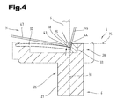
- Fig. 4 is a further and possibly independent execution of the bending tool 4, in particular of the bending die 6 shown, again for like parts, the same reference numerals or component designations as in the preceding Fig. 1 to 3 be used. In order to avoid unnecessary repetition, the detailed description in the previous ones will be used Fig. 1 to 3 referred or referred.
- the workpiece support member 32 is formed such that the bending portion 29 facing end portion 38 of the first and displaceably formed workpiece support member 32 automatically opposite to the sheet to be deformed or the workpiece to be formed. 2 acting bending force (F B ) is formed recoverable. This means that the workpiece support member 32 resets itself automatically starting from its mostly horizontal starting position after the successful bending process and the deformation of the end portion 38 again automatically. This can be done by the material inherent properties.
- the first workpiece support member 32 may also be formed by a leaf spring.
- the end facing away from the bending portion 29 of the leaf spring may be fixedly connected to the main body 26. This ensures that in the starting position, in turn, a horizontal or parallel alignment of the workpiece abutment surface 43 with respect to the workpiece support plane 35 takes place. During the execution of the bending process takes place a constant support of the sheet to be deformed to the deformed workpiece 2 on the self-elastically deformable workpiece support member 32.
- the procedure during the forming process is such that the sheet to be formed is reshaped in a free-form bending operation towards the finished workpiece 2.
- the bending tool 4 with its bending punch 5 and bending die 6 clamp together the tool plane 30, wherein the sheet to be deformed is introduced between the distancing in the starting position bending tool 4 and positioned there.
- Bend is performed by a relative displacement of at least a portion of the bending tool 4, the bending operation of the sheet in the bending region 29. Due to the two-sided arrangement of the sheet with respect to the tool plane 30, first and second legs 46, 47 are formed in the sheet metal. Due to the previously described alignment of the workpiece abutment surface 44 in the area of the further and stationary workpiece support part 33, an asymmetrical deformation of the two legs 46, 47 with respect to their angular orientation to the tool plane 30 occurs.
- the workpiece abutment surface 44 of the further workpiece support member 33 is relatively steeply aligned with respect to the workpiece support plane 35, wherein the complementary angle is between 40 ° and 85 ° with respect to the previously indicated angular range of the angle 45.
- This further angle is in Fig. 3 entered with the reference numeral 48.
- leg 46 which is arranged on the side of the tool plane 30 facing away from the feed side 31, has a longitudinal extension with respect to the tool plane 30 in the direction perpendicular thereto, which is shorter than the longitudinal extension of the leg 47 in the region of the feed side 31, an unwanted deformation of the leg 47 is avoided even in a region outside the bending region 29 even with thin sheets.
- the leg 47 which is usually longer, in the region of the feed side 31 with increasing distance from the tool plane 30 in the event of unsupported support and angular velocity in the direction of the tool plane 30, in addition to the desired bending region 29, causes further undesired deformation experiences. This is prevented by the small displacement and the additional support of the leg 47 in the region of the pivotally formed workpiece support member 32.
Applications Claiming Priority (1)
| Application Number | Priority Date | Filing Date | Title |
|---|---|---|---|
| AT1122011A AT510719B1 (de) | 2011-01-27 | 2011-01-27 | Biegewerkzeug für das freiformbiegen von blechen |
Publications (3)
| Publication Number | Publication Date |
|---|---|
| EP2481492A2 true EP2481492A2 (fr) | 2012-08-01 |
| EP2481492A3 EP2481492A3 (fr) | 2012-10-24 |
| EP2481492B1 EP2481492B1 (fr) | 2016-04-27 |
Family
ID=45524440
Family Applications (1)
| Application Number | Title | Priority Date | Filing Date |
|---|---|---|---|
| EP12152728.7A Not-in-force EP2481492B1 (fr) | 2011-01-27 | 2012-01-26 | Outil de pliage pour le pliage à forme libre de tôles |
Country Status (2)
| Country | Link |
|---|---|
| EP (1) | EP2481492B1 (fr) |
| AT (1) | AT510719B1 (fr) |
Cited By (5)
| Publication number | Priority date | Publication date | Assignee | Title |
|---|---|---|---|---|
| CN103100606A (zh) * | 2013-02-25 | 2013-05-15 | 宁波市令通电信设备有限公司 | 托板机构 |
| CN103100605A (zh) * | 2013-02-25 | 2013-05-15 | 宁波市令通电信设备有限公司 | 折弯机板料托架 |
| CN103100600A (zh) * | 2013-02-25 | 2013-05-15 | 宁波市令通电信设备有限公司 | 一种折弯机板料托架 |
| CN103111537A (zh) * | 2013-02-25 | 2013-05-22 | 宁波市令通电信设备有限公司 | 一种折弯机托板支架 |
| CN109047510A (zh) * | 2018-10-10 | 2018-12-21 | 弗兰卡(中国)厨房系统有限公司 | 一种板材圆弧折弯模具及其加工方法 |
Citations (1)
| Publication number | Priority date | Publication date | Assignee | Title |
|---|---|---|---|---|
| NL1014810C2 (nl) | 2000-03-31 | 2001-10-19 | Adriaan Teunissen | Vervormingsinrichting voor het vervormen van een plaatelement. |
Family Cites Families (8)
| Publication number | Priority date | Publication date | Assignee | Title |
|---|---|---|---|---|
| JPS62127125A (ja) * | 1985-11-28 | 1987-06-09 | Nippon Kokan Kk <Nkk> | 複合型制振鋼板の曲げ金型 |
| US5365766A (en) * | 1993-05-18 | 1994-11-22 | Amada Engineering & Service Co., Inc. | Die assembly having means for automatically controlling in the angular orientation of the lower die plate members |
| JP2760371B2 (ja) * | 1994-06-13 | 1998-05-28 | 株式会社アマダメトレックス | 板材折曲げ加工機の金型 |
| JP2808083B2 (ja) * | 1994-11-14 | 1998-10-08 | 丸機械工業株式会社 | 折曲げ型 |
| GB2368304A (en) * | 2000-06-23 | 2002-05-01 | Taigaa Koosan Yuugenkaisha | Metal sheet bending device with rotation inhibiting function |
| JP4698811B2 (ja) * | 2000-10-13 | 2011-06-08 | 有限会社タイガー恒産 | 金属板の折曲装置 |
| FR2873939B1 (fr) * | 2004-08-09 | 2008-01-11 | Tech Metalliques Appliquees T | Dispositif de pliage d'une tole le long d'une generatrice |
| TWM275895U (en) * | 2005-01-12 | 2005-09-21 | Shu-Ching Lin | Bending structure for stainless steel plate |
-
2011
- 2011-01-27 AT AT1122011A patent/AT510719B1/de not_active IP Right Cessation
-
2012
- 2012-01-26 EP EP12152728.7A patent/EP2481492B1/fr not_active Not-in-force
Patent Citations (1)
| Publication number | Priority date | Publication date | Assignee | Title |
|---|---|---|---|---|
| NL1014810C2 (nl) | 2000-03-31 | 2001-10-19 | Adriaan Teunissen | Vervormingsinrichting voor het vervormen van een plaatelement. |
Cited By (10)
| Publication number | Priority date | Publication date | Assignee | Title |
|---|---|---|---|---|
| CN103100606A (zh) * | 2013-02-25 | 2013-05-15 | 宁波市令通电信设备有限公司 | 托板机构 |
| CN103100605A (zh) * | 2013-02-25 | 2013-05-15 | 宁波市令通电信设备有限公司 | 折弯机板料托架 |
| CN103100600A (zh) * | 2013-02-25 | 2013-05-15 | 宁波市令通电信设备有限公司 | 一种折弯机板料托架 |
| CN103111537A (zh) * | 2013-02-25 | 2013-05-22 | 宁波市令通电信设备有限公司 | 一种折弯机托板支架 |
| CN103100605B (zh) * | 2013-02-25 | 2015-01-21 | 宁波市令通电信设备有限公司 | 折弯机板料托架 |
| CN103100606B (zh) * | 2013-02-25 | 2015-01-21 | 宁波市令通电信设备有限公司 | 托板机构 |
| CN103111537B (zh) * | 2013-02-25 | 2015-04-01 | 宁波市令通电信设备有限公司 | 一种折弯机托板支架 |
| CN103100600B (zh) * | 2013-02-25 | 2015-09-23 | 宁波市令通电信设备有限公司 | 一种折弯机板料托架 |
| CN109047510A (zh) * | 2018-10-10 | 2018-12-21 | 弗兰卡(中国)厨房系统有限公司 | 一种板材圆弧折弯模具及其加工方法 |
| CN109047510B (zh) * | 2018-10-10 | 2024-02-27 | 弗兰卡(中国)厨房系统有限公司 | 一种板材圆弧折弯模具及其加工方法 |
Also Published As
| Publication number | Publication date |
|---|---|
| AT510719B1 (de) | 2012-06-15 |
| AT510719A4 (de) | 2012-06-15 |
| EP2481492B1 (fr) | 2016-04-27 |
| EP2481492A3 (fr) | 2012-10-24 |
Similar Documents
| Publication | Publication Date | Title |
|---|---|---|
| EP2498928B1 (fr) | Installation d'usinage, notamment pour le formage libre avec un manipulateur de pièce et d'outil intégré | |
| AT509980B1 (de) | Fertigungsanlage mit werkzeugspeicher | |
| EP2881188B1 (fr) | Unité de butée arrière pour cintreuse | |
| WO2018071938A1 (fr) | Installation de fabrication présentant un dispositif de manipulation | |
| EP3154722B1 (fr) | Presse à cintrer munie d'une unité de cintrage et procédé de formage | |
| EP2481492B1 (fr) | Outil de pliage pour le pliage à forme libre de tôles | |
| EP3052256A1 (fr) | Presse à plier et procédé de pliage | |
| EP2944390B1 (fr) | Outil de pliage et procédé de changement d'un tel outil | |
| EP2688693B1 (fr) | Installation de fabrication dotée d'un dispositif auxiliaire destiné au positionnement intermédiaire de pièces | |
| EP3302840B1 (fr) | Installation de fabrication pour la fabrication de pièces en tôle et procédé à cet effet | |
| EP3551356B1 (fr) | Installation de fabrication dotée d'un outil de serrage ainsi que procédé de réglage d'une longueur totale d'un bord de pliage de l'outil de serrage | |
| EP2845663B1 (fr) | Presse plieuse avec un outil de cintrage composé de plusieurs éléments d'outil | |
| EP3427853B1 (fr) | Unité de butée arrière ainsi qu'installation de fabrication équipée d'une telle unité de butée arrière | |
| EP1377395B1 (fr) | Machine de pliage, en particulier presse a estamper ou a plier, pourvue d'un outil inferieur reglable | |
| AT520038A1 (de) | Fertigungsanlage mit einer Schutzeinheit | |
| EP3592482A1 (fr) | Installation de fabrication dotée d'une unité de protection | |
| AT510721A4 (de) | Werkzeug-positioniervorrichtung an einer biegepresse | |
| AT518273A4 (de) | Biegewerkzeug sowie Fertigungsanlage mit einer Biegepresse und einem derartigen Biegewerkzeug |
Legal Events
| Date | Code | Title | Description |
|---|---|---|---|
| PUAI | Public reference made under article 153(3) epc to a published international application that has entered the european phase |
Free format text: ORIGINAL CODE: 0009012 |
|
| AK | Designated contracting states |
Kind code of ref document: A2 Designated state(s): AL AT BE BG CH CY CZ DE DK EE ES FI FR GB GR HR HU IE IS IT LI LT LU LV MC MK MT NL NO PL PT RO RS SE SI SK SM TR |
|
| AX | Request for extension of the european patent |
Extension state: BA ME |
|
| PUAL | Search report despatched |
Free format text: ORIGINAL CODE: 0009013 |
|
| AK | Designated contracting states |
Kind code of ref document: A3 Designated state(s): AL AT BE BG CH CY CZ DE DK EE ES FI FR GB GR HR HU IE IS IT LI LT LU LV MC MK MT NL NO PL PT RO RS SE SI SK SM TR |
|
| AX | Request for extension of the european patent |
Extension state: BA ME |
|
| RIC1 | Information provided on ipc code assigned before grant |
Ipc: B21D 5/02 20060101AFI20120918BHEP |
|
| 17P | Request for examination filed |
Effective date: 20130424 |
|
| GRAP | Despatch of communication of intention to grant a patent |
Free format text: ORIGINAL CODE: EPIDOSNIGR1 |
|
| RIC1 | Information provided on ipc code assigned before grant |
Ipc: B21D 5/02 20060101AFI20151021BHEP |
|
| INTG | Intention to grant announced |
Effective date: 20151111 |
|
| GRAS | Grant fee paid |
Free format text: ORIGINAL CODE: EPIDOSNIGR3 |
|
| GRAA | (expected) grant |
Free format text: ORIGINAL CODE: 0009210 |
|
| AK | Designated contracting states |
Kind code of ref document: B1 Designated state(s): AL AT BE BG CH CY CZ DE DK EE ES FI FR GB GR HR HU IE IS IT LI LT LU LV MC MK MT NL NO PL PT RO RS SE SI SK SM TR |
|
| REG | Reference to a national code |
Ref country code: GB Ref legal event code: FG4D Free format text: NOT ENGLISH |
|
| REG | Reference to a national code |
Ref country code: CH Ref legal event code: EP |
|
| REG | Reference to a national code |
Ref country code: AT Ref legal event code: REF Ref document number: 794148 Country of ref document: AT Kind code of ref document: T Effective date: 20160515 |
|
| REG | Reference to a national code |
Ref country code: IE Ref legal event code: FG4D Free format text: LANGUAGE OF EP DOCUMENT: GERMAN |
|
| REG | Reference to a national code |
Ref country code: DE Ref legal event code: R096 Ref document number: 502012006860 Country of ref document: DE |
|
| REG | Reference to a national code |
Ref country code: LT Ref legal event code: MG4D |
|
| REG | Reference to a national code |
Ref country code: NL Ref legal event code: MP Effective date: 20160427 |
|
| PG25 | Lapsed in a contracting state [announced via postgrant information from national office to epo] |
Ref country code: NL Free format text: LAPSE BECAUSE OF FAILURE TO SUBMIT A TRANSLATION OF THE DESCRIPTION OR TO PAY THE FEE WITHIN THE PRESCRIBED TIME-LIMIT Effective date: 20160427 |
|
| PG25 | Lapsed in a contracting state [announced via postgrant information from national office to epo] |
Ref country code: PL Free format text: LAPSE BECAUSE OF FAILURE TO SUBMIT A TRANSLATION OF THE DESCRIPTION OR TO PAY THE FEE WITHIN THE PRESCRIBED TIME-LIMIT Effective date: 20160427 Ref country code: NO Free format text: LAPSE BECAUSE OF FAILURE TO SUBMIT A TRANSLATION OF THE DESCRIPTION OR TO PAY THE FEE WITHIN THE PRESCRIBED TIME-LIMIT Effective date: 20160727 Ref country code: LT Free format text: LAPSE BECAUSE OF FAILURE TO SUBMIT A TRANSLATION OF THE DESCRIPTION OR TO PAY THE FEE WITHIN THE PRESCRIBED TIME-LIMIT Effective date: 20160427 Ref country code: FI Free format text: LAPSE BECAUSE OF FAILURE TO SUBMIT A TRANSLATION OF THE DESCRIPTION OR TO PAY THE FEE WITHIN THE PRESCRIBED TIME-LIMIT Effective date: 20160427 |
|
| PG25 | Lapsed in a contracting state [announced via postgrant information from national office to epo] |
Ref country code: RS Free format text: LAPSE BECAUSE OF FAILURE TO SUBMIT A TRANSLATION OF THE DESCRIPTION OR TO PAY THE FEE WITHIN THE PRESCRIBED TIME-LIMIT Effective date: 20160427 Ref country code: LV Free format text: LAPSE BECAUSE OF FAILURE TO SUBMIT A TRANSLATION OF THE DESCRIPTION OR TO PAY THE FEE WITHIN THE PRESCRIBED TIME-LIMIT Effective date: 20160427 Ref country code: ES Free format text: LAPSE BECAUSE OF FAILURE TO SUBMIT A TRANSLATION OF THE DESCRIPTION OR TO PAY THE FEE WITHIN THE PRESCRIBED TIME-LIMIT Effective date: 20160427 Ref country code: HR Free format text: LAPSE BECAUSE OF FAILURE TO SUBMIT A TRANSLATION OF THE DESCRIPTION OR TO PAY THE FEE WITHIN THE PRESCRIBED TIME-LIMIT Effective date: 20160427 Ref country code: SE Free format text: LAPSE BECAUSE OF FAILURE TO SUBMIT A TRANSLATION OF THE DESCRIPTION OR TO PAY THE FEE WITHIN THE PRESCRIBED TIME-LIMIT Effective date: 20160427 Ref country code: GR Free format text: LAPSE BECAUSE OF FAILURE TO SUBMIT A TRANSLATION OF THE DESCRIPTION OR TO PAY THE FEE WITHIN THE PRESCRIBED TIME-LIMIT Effective date: 20160728 Ref country code: PT Free format text: LAPSE BECAUSE OF FAILURE TO SUBMIT A TRANSLATION OF THE DESCRIPTION OR TO PAY THE FEE WITHIN THE PRESCRIBED TIME-LIMIT Effective date: 20160829 |
|
| REG | Reference to a national code |
Ref country code: FR Ref legal event code: PLFP Year of fee payment: 6 |
|
| PG25 | Lapsed in a contracting state [announced via postgrant information from national office to epo] |
Ref country code: IT Free format text: LAPSE BECAUSE OF FAILURE TO SUBMIT A TRANSLATION OF THE DESCRIPTION OR TO PAY THE FEE WITHIN THE PRESCRIBED TIME-LIMIT Effective date: 20160427 |
|
| REG | Reference to a national code |
Ref country code: DE Ref legal event code: R097 Ref document number: 502012006860 Country of ref document: DE |
|
| PG25 | Lapsed in a contracting state [announced via postgrant information from national office to epo] |
Ref country code: CZ Free format text: LAPSE BECAUSE OF FAILURE TO SUBMIT A TRANSLATION OF THE DESCRIPTION OR TO PAY THE FEE WITHIN THE PRESCRIBED TIME-LIMIT Effective date: 20160427 Ref country code: EE Free format text: LAPSE BECAUSE OF FAILURE TO SUBMIT A TRANSLATION OF THE DESCRIPTION OR TO PAY THE FEE WITHIN THE PRESCRIBED TIME-LIMIT Effective date: 20160427 Ref country code: RO Free format text: LAPSE BECAUSE OF FAILURE TO SUBMIT A TRANSLATION OF THE DESCRIPTION OR TO PAY THE FEE WITHIN THE PRESCRIBED TIME-LIMIT Effective date: 20160427 Ref country code: SK Free format text: LAPSE BECAUSE OF FAILURE TO SUBMIT A TRANSLATION OF THE DESCRIPTION OR TO PAY THE FEE WITHIN THE PRESCRIBED TIME-LIMIT Effective date: 20160427 Ref country code: DK Free format text: LAPSE BECAUSE OF FAILURE TO SUBMIT A TRANSLATION OF THE DESCRIPTION OR TO PAY THE FEE WITHIN THE PRESCRIBED TIME-LIMIT Effective date: 20160427 |
|
| PG25 | Lapsed in a contracting state [announced via postgrant information from national office to epo] |
Ref country code: SM Free format text: LAPSE BECAUSE OF FAILURE TO SUBMIT A TRANSLATION OF THE DESCRIPTION OR TO PAY THE FEE WITHIN THE PRESCRIBED TIME-LIMIT Effective date: 20160427 |
|
| PLBE | No opposition filed within time limit |
Free format text: ORIGINAL CODE: 0009261 |
|
| STAA | Information on the status of an ep patent application or granted ep patent |
Free format text: STATUS: NO OPPOSITION FILED WITHIN TIME LIMIT |
|
| 26N | No opposition filed |
Effective date: 20170130 |
|
| PG25 | Lapsed in a contracting state [announced via postgrant information from national office to epo] |
Ref country code: BE Free format text: LAPSE BECAUSE OF NON-PAYMENT OF DUE FEES Effective date: 20170131 Ref country code: SI Free format text: LAPSE BECAUSE OF FAILURE TO SUBMIT A TRANSLATION OF THE DESCRIPTION OR TO PAY THE FEE WITHIN THE PRESCRIBED TIME-LIMIT Effective date: 20160427 |
|
| REG | Reference to a national code |
Ref country code: CH Ref legal event code: PL |
|
| GBPC | Gb: european patent ceased through non-payment of renewal fee |
Effective date: 20170126 |
|
| PG25 | Lapsed in a contracting state [announced via postgrant information from national office to epo] |
Ref country code: MC Free format text: LAPSE BECAUSE OF FAILURE TO SUBMIT A TRANSLATION OF THE DESCRIPTION OR TO PAY THE FEE WITHIN THE PRESCRIBED TIME-LIMIT Effective date: 20160427 |
|
| PG25 | Lapsed in a contracting state [announced via postgrant information from national office to epo] |
Ref country code: LI Free format text: LAPSE BECAUSE OF NON-PAYMENT OF DUE FEES Effective date: 20170131 Ref country code: CH Free format text: LAPSE BECAUSE OF NON-PAYMENT OF DUE FEES Effective date: 20170131 |
|
| REG | Reference to a national code |
Ref country code: IE Ref legal event code: MM4A |
|
| PG25 | Lapsed in a contracting state [announced via postgrant information from national office to epo] |
Ref country code: LU Free format text: LAPSE BECAUSE OF NON-PAYMENT OF DUE FEES Effective date: 20170126 Ref country code: GB Free format text: LAPSE BECAUSE OF NON-PAYMENT OF DUE FEES Effective date: 20170126 |
|
| REG | Reference to a national code |
Ref country code: FR Ref legal event code: PLFP Year of fee payment: 7 |
|
| REG | Reference to a national code |
Ref country code: BE Ref legal event code: MM Effective date: 20170131 |
|
| PG25 | Lapsed in a contracting state [announced via postgrant information from national office to epo] |
Ref country code: IE Free format text: LAPSE BECAUSE OF NON-PAYMENT OF DUE FEES Effective date: 20170126 |
|
| REG | Reference to a national code |
Ref country code: AT Ref legal event code: MM01 Ref document number: 794148 Country of ref document: AT Kind code of ref document: T Effective date: 20170126 |
|
| PG25 | Lapsed in a contracting state [announced via postgrant information from national office to epo] |
Ref country code: AT Free format text: LAPSE BECAUSE OF NON-PAYMENT OF DUE FEES Effective date: 20170126 |
|
| REG | Reference to a national code |
Ref country code: DE Ref legal event code: R082 Ref document number: 502012006860 Country of ref document: DE Representative=s name: ABP BURGER RECHTSANWALTSGESELLSCHAFT MBH, DE |
|
| PG25 | Lapsed in a contracting state [announced via postgrant information from national office to epo] |
Ref country code: MT Free format text: LAPSE BECAUSE OF FAILURE TO SUBMIT A TRANSLATION OF THE DESCRIPTION OR TO PAY THE FEE WITHIN THE PRESCRIBED TIME-LIMIT Effective date: 20160427 |
|
| PG25 | Lapsed in a contracting state [announced via postgrant information from national office to epo] |
Ref country code: AL Free format text: LAPSE BECAUSE OF FAILURE TO SUBMIT A TRANSLATION OF THE DESCRIPTION OR TO PAY THE FEE WITHIN THE PRESCRIBED TIME-LIMIT Effective date: 20160427 |
|
| PG25 | Lapsed in a contracting state [announced via postgrant information from national office to epo] |
Ref country code: HU Free format text: LAPSE BECAUSE OF FAILURE TO SUBMIT A TRANSLATION OF THE DESCRIPTION OR TO PAY THE FEE WITHIN THE PRESCRIBED TIME-LIMIT; INVALID AB INITIO Effective date: 20120126 |
|
| PG25 | Lapsed in a contracting state [announced via postgrant information from national office to epo] |
Ref country code: BG Free format text: LAPSE BECAUSE OF FAILURE TO SUBMIT A TRANSLATION OF THE DESCRIPTION OR TO PAY THE FEE WITHIN THE PRESCRIBED TIME-LIMIT Effective date: 20160427 |
|
| PG25 | Lapsed in a contracting state [announced via postgrant information from national office to epo] |
Ref country code: CY Free format text: LAPSE BECAUSE OF NON-PAYMENT OF DUE FEES Effective date: 20160427 |
|
| PG25 | Lapsed in a contracting state [announced via postgrant information from national office to epo] |
Ref country code: MK Free format text: LAPSE BECAUSE OF FAILURE TO SUBMIT A TRANSLATION OF THE DESCRIPTION OR TO PAY THE FEE WITHIN THE PRESCRIBED TIME-LIMIT Effective date: 20160427 |
|
| PG25 | Lapsed in a contracting state [announced via postgrant information from national office to epo] |
Ref country code: TR Free format text: LAPSE BECAUSE OF FAILURE TO SUBMIT A TRANSLATION OF THE DESCRIPTION OR TO PAY THE FEE WITHIN THE PRESCRIBED TIME-LIMIT Effective date: 20160427 |
|
| PGFP | Annual fee paid to national office [announced via postgrant information from national office to epo] |
Ref country code: FR Payment date: 20200107 Year of fee payment: 9 |
|
| PG25 | Lapsed in a contracting state [announced via postgrant information from national office to epo] |
Ref country code: IS Free format text: LAPSE BECAUSE OF FAILURE TO SUBMIT A TRANSLATION OF THE DESCRIPTION OR TO PAY THE FEE WITHIN THE PRESCRIBED TIME-LIMIT Effective date: 20160827 |
|
| PG25 | Lapsed in a contracting state [announced via postgrant information from national office to epo] |
Ref country code: FR Free format text: LAPSE BECAUSE OF NON-PAYMENT OF DUE FEES Effective date: 20210131 |
|
| PGFP | Annual fee paid to national office [announced via postgrant information from national office to epo] |
Ref country code: DE Payment date: 20211202 Year of fee payment: 11 |
|
| REG | Reference to a national code |
Ref country code: DE Ref legal event code: R119 Ref document number: 502012006860 Country of ref document: DE |
|
| PG25 | Lapsed in a contracting state [announced via postgrant information from national office to epo] |
Ref country code: DE Free format text: LAPSE BECAUSE OF NON-PAYMENT OF DUE FEES Effective date: 20230801 |