EP2480265B1 - Brusthaube zum abpumpen von menschlicher muttermilch - Google Patents
Brusthaube zum abpumpen von menschlicher muttermilch Download PDFInfo
- Publication number
- EP2480265B1 EP2480265B1 EP10760581.8A EP10760581A EP2480265B1 EP 2480265 B1 EP2480265 B1 EP 2480265B1 EP 10760581 A EP10760581 A EP 10760581A EP 2480265 B1 EP2480265 B1 EP 2480265B1
- Authority
- EP
- European Patent Office
- Prior art keywords
- breast
- breast shield
- funnel
- connector
- milk
- Prior art date
- Legal status (The legal status is an assumption and is not a legal conclusion. Google has not performed a legal analysis and makes no representation as to the accuracy of the status listed.)
- Active
Links
- 210000000481 breast Anatomy 0.000 title claims description 134
- 235000020256 human milk Nutrition 0.000 title claims description 14
- 230000008878 coupling Effects 0.000 claims description 40
- 238000010168 coupling process Methods 0.000 claims description 40
- 238000005859 coupling reaction Methods 0.000 claims description 40
- 230000007704 transition Effects 0.000 claims description 10
- 210000002445 nipple Anatomy 0.000 claims description 8
- 210000004251 human milk Anatomy 0.000 claims description 6
- 210000004883 areola Anatomy 0.000 claims description 5
- 229920001296 polysiloxane Polymers 0.000 claims description 4
- 239000012530 fluid Substances 0.000 claims description 3
- 238000004891 communication Methods 0.000 claims description 2
- 230000000284 resting effect Effects 0.000 claims description 2
- 238000007789 sealing Methods 0.000 claims 1
- 235000013336 milk Nutrition 0.000 description 66
- 239000008267 milk Substances 0.000 description 66
- 210000004080 milk Anatomy 0.000 description 66
- 238000005086 pumping Methods 0.000 description 43
- 210000004379 membrane Anatomy 0.000 description 28
- 239000012528 membrane Substances 0.000 description 27
- 210000000038 chest Anatomy 0.000 description 9
- 239000000463 material Substances 0.000 description 3
- 210000001519 tissue Anatomy 0.000 description 3
- 230000005540 biological transmission Effects 0.000 description 2
- 238000011109 contamination Methods 0.000 description 2
- 238000003780 insertion Methods 0.000 description 2
- 230000037431 insertion Effects 0.000 description 2
- 238000000926 separation method Methods 0.000 description 2
- 206010029421 Nipple pain Diseases 0.000 description 1
- 238000013459 approach Methods 0.000 description 1
- 210000003323 beak Anatomy 0.000 description 1
- 238000012790 confirmation Methods 0.000 description 1
- 230000001419 dependent effect Effects 0.000 description 1
- 238000004146 energy storage Methods 0.000 description 1
- 238000000034 method Methods 0.000 description 1
- 238000005192 partition Methods 0.000 description 1
- 230000008092 positive effect Effects 0.000 description 1
- 239000007779 soft material Substances 0.000 description 1
- 239000007787 solid Substances 0.000 description 1
Images


Classifications
-
- A—HUMAN NECESSITIES
- A61—MEDICAL OR VETERINARY SCIENCE; HYGIENE
- A61M—DEVICES FOR INTRODUCING MEDIA INTO, OR ONTO, THE BODY; DEVICES FOR TRANSDUCING BODY MEDIA OR FOR TAKING MEDIA FROM THE BODY; DEVICES FOR PRODUCING OR ENDING SLEEP OR STUPOR
- A61M1/00—Suction or pumping devices for medical purposes; Devices for carrying-off, for treatment of, or for carrying-over, body-liquids; Drainage systems
- A61M1/06—Milking pumps
-
- A—HUMAN NECESSITIES
- A41—WEARING APPAREL
- A41C—CORSETS; BRASSIERES
- A41C3/00—Brassieres
- A41C3/06—Strapless brassieres, i.e. without shoulder straps
- A41C3/065—Strapless brassieres, i.e. without shoulder straps attached directly to the body, e.g. by means of adhesive
-
- A—HUMAN NECESSITIES
- A61—MEDICAL OR VETERINARY SCIENCE; HYGIENE
- A61F—FILTERS IMPLANTABLE INTO BLOOD VESSELS; PROSTHESES; DEVICES PROVIDING PATENCY TO, OR PREVENTING COLLAPSING OF, TUBULAR STRUCTURES OF THE BODY, e.g. STENTS; ORTHOPAEDIC, NURSING OR CONTRACEPTIVE DEVICES; FOMENTATION; TREATMENT OR PROTECTION OF EYES OR EARS; BANDAGES, DRESSINGS OR ABSORBENT PADS; FIRST-AID KITS
- A61F13/00—Bandages or dressings; Absorbent pads
- A61F13/01—Non-adhesive bandages or dressings
- A61F13/01034—Non-adhesive bandages or dressings characterised by a property
- A61F13/01038—Flexibility, stretchability or elasticity
-
- A—HUMAN NECESSITIES
- A61—MEDICAL OR VETERINARY SCIENCE; HYGIENE
- A61J—CONTAINERS SPECIALLY ADAPTED FOR MEDICAL OR PHARMACEUTICAL PURPOSES; DEVICES OR METHODS SPECIALLY ADAPTED FOR BRINGING PHARMACEUTICAL PRODUCTS INTO PARTICULAR PHYSICAL OR ADMINISTERING FORMS; DEVICES FOR ADMINISTERING FOOD OR MEDICINES ORALLY; BABY COMFORTERS; DEVICES FOR RECEIVING SPITTLE
- A61J13/00—Breast-nipple shields
-
- A—HUMAN NECESSITIES
- A61—MEDICAL OR VETERINARY SCIENCE; HYGIENE
- A61M—DEVICES FOR INTRODUCING MEDIA INTO, OR ONTO, THE BODY; DEVICES FOR TRANSDUCING BODY MEDIA OR FOR TAKING MEDIA FROM THE BODY; DEVICES FOR PRODUCING OR ENDING SLEEP OR STUPOR
- A61M1/00—Suction or pumping devices for medical purposes; Devices for carrying-off, for treatment of, or for carrying-over, body-liquids; Drainage systems
- A61M1/06—Milking pumps
- A61M1/062—Pump accessories
- A61M1/064—Suction cups
-
- A—HUMAN NECESSITIES
- A61—MEDICAL OR VETERINARY SCIENCE; HYGIENE
- A61M—DEVICES FOR INTRODUCING MEDIA INTO, OR ONTO, THE BODY; DEVICES FOR TRANSDUCING BODY MEDIA OR FOR TAKING MEDIA FROM THE BODY; DEVICES FOR PRODUCING OR ENDING SLEEP OR STUPOR
- A61M1/00—Suction or pumping devices for medical purposes; Devices for carrying-off, for treatment of, or for carrying-over, body-liquids; Drainage systems
- A61M1/06—Milking pumps
- A61M1/062—Pump accessories
- A61M1/067—Pump accessories with means for hands-free operation
-
- A—HUMAN NECESSITIES
- A61—MEDICAL OR VETERINARY SCIENCE; HYGIENE
- A61M—DEVICES FOR INTRODUCING MEDIA INTO, OR ONTO, THE BODY; DEVICES FOR TRANSDUCING BODY MEDIA OR FOR TAKING MEDIA FROM THE BODY; DEVICES FOR PRODUCING OR ENDING SLEEP OR STUPOR
- A61M1/00—Suction or pumping devices for medical purposes; Devices for carrying-off, for treatment of, or for carrying-over, body-liquids; Drainage systems
- A61M1/06—Milking pumps
- A61M1/069—Means for improving milking yield
- A61M1/0693—Means for improving milking yield with programmable or pre-programmed sucking patterns
- A61M1/06935—Means for improving milking yield with programmable or pre-programmed sucking patterns imitating the suckling of an infant
-
- A—HUMAN NECESSITIES
- A61—MEDICAL OR VETERINARY SCIENCE; HYGIENE
- A61M—DEVICES FOR INTRODUCING MEDIA INTO, OR ONTO, THE BODY; DEVICES FOR TRANSDUCING BODY MEDIA OR FOR TAKING MEDIA FROM THE BODY; DEVICES FOR PRODUCING OR ENDING SLEEP OR STUPOR
- A61M1/00—Suction or pumping devices for medical purposes; Devices for carrying-off, for treatment of, or for carrying-over, body-liquids; Drainage systems
- A61M1/06—Milking pumps
- A61M1/069—Means for improving milking yield
- A61M1/0697—Means for improving milking yield having means for massaging the breast
-
- A—HUMAN NECESSITIES
- A61—MEDICAL OR VETERINARY SCIENCE; HYGIENE
- A61M—DEVICES FOR INTRODUCING MEDIA INTO, OR ONTO, THE BODY; DEVICES FOR TRANSDUCING BODY MEDIA OR FOR TAKING MEDIA FROM THE BODY; DEVICES FOR PRODUCING OR ENDING SLEEP OR STUPOR
- A61M1/00—Suction or pumping devices for medical purposes; Devices for carrying-off, for treatment of, or for carrying-over, body-liquids; Drainage systems
- A61M1/80—Suction pumps
- A61M1/82—Membrane pumps, e.g. bulbs
-
- F—MECHANICAL ENGINEERING; LIGHTING; HEATING; WEAPONS; BLASTING
- F02—COMBUSTION ENGINES; HOT-GAS OR COMBUSTION-PRODUCT ENGINE PLANTS
- F02M—SUPPLYING COMBUSTION ENGINES IN GENERAL WITH COMBUSTIBLE MIXTURES OR CONSTITUENTS THEREOF
- F02M61/00—Fuel-injectors not provided for in groups F02M39/00 - F02M57/00 or F02M67/00
- F02M61/04—Fuel-injectors not provided for in groups F02M39/00 - F02M57/00 or F02M67/00 having valves, e.g. having a plurality of valves in series
- F02M61/08—Fuel-injectors not provided for in groups F02M39/00 - F02M57/00 or F02M67/00 having valves, e.g. having a plurality of valves in series the valves opening in direction of fuel flow
-
- A—HUMAN NECESSITIES
- A61—MEDICAL OR VETERINARY SCIENCE; HYGIENE
- A61M—DEVICES FOR INTRODUCING MEDIA INTO, OR ONTO, THE BODY; DEVICES FOR TRANSDUCING BODY MEDIA OR FOR TAKING MEDIA FROM THE BODY; DEVICES FOR PRODUCING OR ENDING SLEEP OR STUPOR
- A61M1/00—Suction or pumping devices for medical purposes; Devices for carrying-off, for treatment of, or for carrying-over, body-liquids; Drainage systems
- A61M1/06—Milking pumps
- A61M1/062—Pump accessories
- A61M1/064—Suction cups
- A61M1/066—Inserts therefor
-
- A—HUMAN NECESSITIES
- A61—MEDICAL OR VETERINARY SCIENCE; HYGIENE
- A61M—DEVICES FOR INTRODUCING MEDIA INTO, OR ONTO, THE BODY; DEVICES FOR TRANSDUCING BODY MEDIA OR FOR TAKING MEDIA FROM THE BODY; DEVICES FOR PRODUCING OR ENDING SLEEP OR STUPOR
- A61M2202/00—Special media to be introduced, removed or treated
- A61M2202/0014—Special media to be introduced, removed or treated removed from the body
Definitions
- the present invention relates to a breast shield for pumping out human breast milk according to the preamble of patent claim 1 and to a breast shield set according to the preamble of patent claim 11.
- the breast shield usually has a funnel-shaped part for receiving a part of the mother's breast including the nipple. As a rule, this funnel-shaped part merges into a hollow-cylindrical part to which, on the one hand, either the vacuum pump or the suction line is connected directly and which, on the other hand, is likewise connected directly or via a milk line to a milk collecting container. It is known to select breast caps according to the size of the breast. In particular, breast shield sets are known in which the size of the funnel-shaped part of the mother can be selected accordingly.
- WO 02/102437 and WO 2008/137678 show "hands-free" pumping devices.
- the breast shield is integrated in each case in a pump housing and also serves as a membrane for generating a negative pressure.
- US 949 414 describes a funnel-shaped breast shield, which can be placed under a brassiere. A vacuum is not applied, but a hose leads from the breast shield to a baby, which should receive the desired milk by sucking on the tube.
- US 6,440,100 shows a device for pumping breast milk with a small breast cap portable under the brassiere.
- a milk hose leads from the breast cap to a milk collection container.
- This is connected via a vacuum hose to a vacuum source.
- the milk collecting container is evacuated by means of the vacuum source, wherein the negative pressure is applied via the milk hose to the breast shield. Thanks to the negative pressure prevailing in the milk collection container, pumped milk should now reach the milk collection container via the milk hose.
- the milk container itself can serve as a vacuum pump.
- This device has the disadvantage that the relatively large volume of the milk collection container must also be evacuated. This so-called dead volume massively limits the performance of the device.
- US 2005/222536 discloses a breast shield in the form of a hollow cylinder with straight running coat.
- the breast cap is made of a very soft material.
- US 2004/087898 shows a breast shield with a funnel and a flexible insert. This insert may vary in shape to massage the breast.
- WO 2008/090386 relates to a device with a hard shell and a soft inner part. This part deforms when it is put on a breast.
- the hard part can be part of a breast pump, ie a breast shield, or be taken directly from the baby into the mouth.
- the breast cap according to the invention has a tubular neck and a funnel integrally formed thereon for resting on a mother's breast, wherein the funnel widens toward its free side facing away from the neck and wherein there is a channel which extends continuously from a breast-side end of the funnel extends to a, opposite this end, pump-side end of the nozzle and which serves for applying a vacuum to the mother's breast and to drain the pumped breast milk.
- the funnel is made more flexible than the nozzle.
- the hopper has a main portion extending over a substantial part of its length, having a first opening angle of the channel and a chest-side end portion having a second opening angle of the channel. When not in use, the first opening angle is smaller than the second opening angle, wherein in the state of use at least the first opening angle can be increased by axial pressure on the breastshield.
- This breast cap adapts optimally to the shape of the human mother's breast and creates a dense or less dense connection with the breast, depending on your wishes or pressure.
- the breast shield is so small that it surrounds only the nipple and at most the areola.
- This can not only be easily used in a "hands-free" system, eg hold in a brush holder, but it has due to their small size hardly air-filled areas. This has a positive effect on the Vacuum pump, since this requires less power and thus can work quieter. Furthermore, she can also be trained for this reason smaller.
- These small breast caps also have the advantage that less tissue movement of the breast can take place within the hood.
- the breast caps can thereby fit closer to the tissue. This in turn requires a lower pumping capacity.
- the pump can also be made smaller and works quieter.
- the nipple in the inventive breast shield is usually not stretched to 2.5 times its length. This is pleasant for the mother, especially with sore nipples.
- typical values of the first opening angle of the breast shield are ⁇ 5 ° (less than or equal to 5 °) and the second opening angle 90 ° to 160 °.
- at least the second opening angle can be increased up to 120 ° or preferably up to 160 °.
- the funnel has a breast-side diameter of 5 mm to 40 mm and a length of 10 mm to 40 mm, so that in use the nipple and at most the areola is covered by the breast shield. Milk channels in the breast tissue are preferably not surrounded by the breast shield.
- a transition region is present between the nozzle and the funnel with a third opening angle of the channel, wherein the third opening angle when not in use is greater than the first opening angle.
- Typical values of the third opening angle are 60 ° to 150 °.
- the main area directly adjoins the transition area.
- the end area also preferably connects directly to the main area.
- the neck has a much larger Wall thickness as the funnel: Additionally or alternatively, the neck can also be formed of a material with a greater Shore hardness.
- an outer stopper is provided, which protrudes the outer circumference of the nozzle.
- the neck can be easily inserted into a receptacle, if it is designed widening in its outer periphery conically towards the funnel.
- This breast cap according to the invention is preferably made of silicone and preferably has a Shore A hardness of 30 to 70.
- the funnel has a Shore A hardness of about 50 and the neck has a Shore A hardness of about 70.
- this relatively small and compact breast shield can be held well in the hand, it is preferably offered in a breast shield set with a coupling part.
- the coupling member is used for sealingly receiving the neck of the breast shield, wherein it is cylindrical and is closed on one side with a bottom, so that a blind hole for receiving the nozzle is formed.
- the at least one connection opening is arranged acentrically in the coupling part.
- connection opening is arranged in an upper region of the coupling part and the coupling part has a marking which defines "upwards" in space, air bubbles in the coupling part which are present during pumping are avoided and air-filled dead spaces are eliminated.
- the blind hole of the coupling part tapers in diameter towards the ground.
- the coupling member is formed stiff, which facilitates the insertion of the nozzle and increases the stability.
- the part can thus be easier to hold or fasten.
- the breast shield has no inserts and consists only of the above elements.
- the inventive breast cap can be combined with all types of breast pumps.
- Such a device for pumping out human breast milk has the inventive breast shield for abutment with a mother's breast, a vacuum pump for generating a vacuum, a line connecting the breast shield with the pumping chamber for transmitting the generated vacuum to the breast shield and a chamber.
- the line ends on the pump side in a first port of this chamber.
- the chamber has a second connection for connection to a milk collection container. The two ports are in fluid communicating communication within the chamber.
- the line forms during the pumping down a milk line for the transport of breast milk pumped in the breast cap to the chamber. The milk is then passed from the chamber to the milk collection container.
- a lower pumping power is necessary to Pump off breast milk.
- Typical values for the air delivery rate are a maximum of 50 ml / min and for the milk delivery rate max. 100 ml / min.
- the vacuum pump can thus be made smaller and lighter, which in turn is less noticeable to outsiders. The mother can use this vacuum pump more discreetly. The lower pumping requirement also makes the vacuum pump quieter in use, which in turn increases comfort and discretion.
- the entire system i. the entire system is flooded with milk down to the pump unit side or drive side area of the vacuum pump and there are no or only very small air-filled dead spaces, it is easier to control the applied vacuum.
- the negative pressure applied to the breast shield also corresponds more closely to the vacuum generated in the vacuum pump.
- This milk line can be realized in different ways.
- a septum is present which separates a drive of the vacuum pump and the conduit from each other.
- the chamber is thereby subdivided by the septum into a chest-side area and a drive-side area.
- the two areas are completely separated and connected only by the membrane. This ensures that neither milk gets into the drive-side region of the vacuum pump, nor that contamination or air of the drive-side region in the milk-carrying line and thus enters the breast shield and the milk collection container.
- this septum is a membrane.
- This membrane is driven in a preferred embodiment and serves to convey the pumped milk.
- the milk can be pumped to each other regardless of the relative position of the breast cap, the milk collection container and the vacuum pump.
- the mother can also drain lying down. This is ideal especially for a "hands-free" version, because the mother can bend over and in general can move very freely.
- vacuum pumps can be used a variety of vacuum pumps with the inventive vacuum-conveying and milk-carrying line.
- a single membrane is used both for the transport of the milk as well as for the media separation.
- the vacuum pump is a diaphragm pump, wherein the chamber is the vacuum-generating pumping chamber of the vacuum pump and the diaphragm is the diaphragm of the pumping chamber used to generate the vacuum.
- the breast cap can also be connected directly to a housing of a vacuum pump without the above-described line. Nevertheless, you can switch to a hydraulic pumping system.
- a preferred vacuum pump for pumping human breast milk by means of this breast cap has a drive and a cyclically driven by the drive membrane, wherein the membrane is arranged in a chamber, the membrane separating the chamber in a drive-side part and a chest part and wherein the chest side Part has a vacuum connection for establishing a connection to the breast shield.
- the breast-hood-side part of the chamber further has a milk connection for establishing a connection with a milk collection container, and the vacuum connection and the milk connection are in fluid-communicating connection with each other via the chest-side part of the chamber.
- this vacuum pump is a diaphragm pump and the chamber is the vacuum-generating pumping chamber.
- the vacuum pump is an electric diaphragm pump.
- the membrane of the membrane pump preferably forms the membrane called the milk drive and septum mentioned above.
- the drive of the membrane preferably serves simultaneously to generate the vacuum in the pumping chamber and to promote the flow of milk. Thanks to the triple function of the membrane, the vacuum can be better controlled.
- the membrane has a substantially circular floor plan.
- the membrane is in its central region, preferably its center, driven.
- diaphragm pumps and alternative pumps without a diaphragm can be used.
- manually operated pumps can be used.
- FIGS. 1 to 3 a preferred example of a breast cap 4 according to the invention is shown.
- she is visible in a breast cap set with coupling part 3.
- FIG. 1 shows the inventive breast cap 4, as it is applied to a female breast B.
- the breast cap 4 has a neck 40, a funnel 42 and a transition region 44 connecting these two.
- a radially outwardly projecting flange 41 is present between nozzle 40 and funnel 42.
- a continuous channel 43 extends through the entire breast shield 4, so that it is open at two opposite ends.
- the breast shield 4 is rotationally symmetrical.
- the breast shield 4 has no further elements, in particular no inserts.
- the breast shield 4 is integrally formed. It usually consists of plastic, preferably silicone.
- the nozzle 40 is solid, i. It has a much greater wall thickness than the funnel 42.
- the neck 40 is conically formed on its outer circumference, wherein it is preferably rotationally symmetrical.
- the conicity facilitates insertion into the coupling part 3 and also increases the tightness of the connection with the coupling part 3.
- the tightness is further achieved by the neck 40 is slightly compressed due to the material in the coupling part.
- the outer diameter of the nozzle 40 is slightly larger than the inner diameter of the coupling part 3.
- Typical outer diameter of the nozzle 40 are 8 mm to 40 mm. Typical lengths are 5 mm to 40 mm.
- the funnel 42 serves to receive the mother's breast. He is preferably designed very flexible. It is much more flexible and softer than the neck 40. Thanks to its flexibility, it adapts in shape to the shape of the breast. He has here a much smaller wall thickness than the nozzle 40.
- nozzle 40 and funnel 42 may also have the same wall thickness, in which case the nozzle 40 is preferably made of a material having a greater Shore hardness or has a gain.
- the funnel 42 has a Shore A hardness of about 50 and the nozzle 40 has a Shore A hardness of about 70.
- the funnel 42 has at least two regions: a main region 420 and a front, chest hood-side end region 421.
- the end region 421 forms the breast-hood-side end of the breast shield and thus ends free.
- the main area 420 When not in use, the main area 420 has a first opening angle ⁇ 1 and the end area has a second opening angle ⁇ 2 .
- the first opening angle ⁇ 1 is smaller than the second opening angle ⁇ 2 .
- the wall in the end region 421, the wall is preferably bent outward. As in the Figures 1 and 2 can be seen, the first opening angle ⁇ 1 can be increased at an axial contact pressure on the chest, so that the end portion 421 can optimally adapt to the shape of the breast.
- the main area 420 directly adjoins the end area 421.
- the main area 420 immediately adjoins the transition area 44 at the other end.
- a further third opening angle ⁇ 3 is present, which is also greater than the first opening angle of the main area 420. This serves as the default for the main area when enlarging the angle.
- the angles when not in use are preferably for the first opening angle ⁇ 1 ⁇ 0.5 °, for the second opening angle ⁇ 2 . 90 ° to 160 ° and for the third opening angle ⁇ 3 60 ° to 150 °. At least the first opening angle ⁇ 1 can be increased in use, preferably to an angle of up to 10 °.
- the funnel 42 has a length L of 10 mm to 40 mm.
- the diameter D in the front end region is preferably 5 mm to 40 mm, in particular 20 mm to 40 mm.
- the funnel 42 is frusto-conical shaped in the region of the neck 40, wherein it opens to the chest. Its front, breast-side edge is more inclined to the outside than the socket-side part.
- the mother can choose how much of the breast is actually covered by the breast shield 4 by choosing the contact pressure.
- the contact pressure results from the axial pressure on the funnel 42 and the back pressure of the mother's breast.
- FIG. 1 is the contact pressure relatively large and the funnel spread
- FIG. 2 the pressure is smaller and the funnel 42 encloses only the nipple.
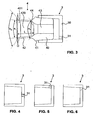
- the breast shield 4 is as in FIG. 3 can be seen, plugged into the coupling part 3.
- the coupling part 3 is preferably also small, but designed as stiff as possible. It is preferably cylindrical in its outer periphery and frustoconical or conical in its inner periphery. It has a U-shaped cross-section, that is, it is open at one end and closed at the opposite end. Thus, a blind hole is present, in which the nozzle 40 of the breast cap 4 can be inserted up to the stop 41. In FIG. 3 the breast cap 4 is not yet fully inserted. However, as can be seen, in the fully inserted state between the end-side end of the connecting piece 40 and the rear wall of the coupling part 3 there is a gap which forms a fluid passage from the channel 43 to a connection opening 31 in the coupling part 3.
- connection opening 31 serves to connect a vacuum and / or milk line. If the vacuum line and milk line run separately from one another, then two connection openings are present in the coupling part 3. These connection openings can be provided with check valves.
- the vacuum line leads to the vacuum pump, the milk line to the milk collection container.
- the cables can simply be plugged into the openings. But they can also be firmly connected to the coupling part 3 or it can be on or Aufstecksch, for example, nozzles, for connection to the lines.
- the at least one connection opening 31 can be attached to different locations.
- FIG. 3 it is arranged in the upper region in the rear wall of the coupling part 3.
- FIG. 4 it is arranged in the middle of the back wall.
- FIG. 5 it is located in the mantle, but in the rear, near the rear wall area. Preferably also in the upper area.
- FIG. 6 again shows the situation according to FIG. 3 , but without inserted breast shield 4.
- connection opening 31 is arranged at the top, in particular for the milk line, then the residual air present in the coupling part 3 is sucked out together with the milk and the dead volume is reduced again.
- Breast cover 4 and coupling part 3 have no more air chambers in use. Your space, if still available, are filled with milk.
- the connection opening 31 in use actually upwards is directed, for example, a corresponding mark on the coupling part 3 may be specified.
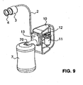
- This breastplate can be used with all types of breastpumps. However, it is advantageous when used with in the FIGS. 7 to 9 illustrated devices for pumping human breast milk.
- FIGS. 7 and 8 a first embodiment of such a device is shown. It has a vacuum pump 1, a first line 2, the coupling part 3, the breastshield 4, a check valve 5, a second line 6 and a milk collecting container 7.
- the breast cap 4 is connected to the vacuum pump 1 via the coupling part 3 and the first flexible conduit 2. From the vacuum pump 1, the second flexible conduit 6 leads to the milk collecting container 7, this connection being provided with the check valve 5.
- the two flexible lines 2, 6 are preferably hoses, in particular of silicone.
- the milk collection container 7 may alternatively be attached directly to the vacuum pump 1.
- a suitably shaped connection piece 70 is preferably provided on the milk collection container 7, which is detachably connectable to a housing 10 of the vacuum pump.
- the vacuum pump 1 has said housing 10, wherein in the drawings, a side wall of the housing 10 is not shown. As a result, the interior of the housing 10 can be seen.
- an electric motor 11 is present. It can be network operated and / or battery powered.
- the connecting rod 12 is connected at its second end with a membrane 14.
- the membrane 14 is arranged in a recess of the housing 10, which forms part of a pumping chamber.
- a releasably connectable to the housing 10 Lid 13 holds the membrane 14 in position.
- the lid 13 is preferably screwed to the housing 10. Other types of connections are also possible.
- the lid 13 also has a recess so that it forms a second part of the pumping chamber. The two parts of the pumping chamber are separated by the membrane 14.
- the lid 13 may be formed in one piece or in several pieces.
- the membrane By means of a drive, here by means of motor 11 and connecting rod 12, the membrane is cyclically reciprocated, so that a negative pressure is generated in the chest-side or cover-side part of the pumping chamber.
- a drive here by means of motor 11 and connecting rod 12, the membrane is cyclically reciprocated, so that a negative pressure is generated in the chest-side or cover-side part of the pumping chamber.
- other types of drives can be used, which are suitable to move the membrane 14 cyclically.
- the necessary for the operation of the pump electronics and the controls are not shown here.
- Known agents can be used.
- the pump can be operated with a temporally constant cycle or the suction curve, as is known in the art, be adapted in shape, frequency and intensity, the Saugvechalten of the infant and / or the needs of the mother.
- a first outlet opening 130 is provided, which connects the environment with the cover-side part of the pumping chamber.
- This outlet opening 130 serves as the first connection for the first line 2.
- a second outlet opening 131 which likewise connects the cover or breast-side part of the pumping chamber to the surroundings, is designed as a second connection.
- This second connection is provided with the check valve 5.
- a beak valve is used, which is attached to a socket. Other types of valves can also be used.
- the breast shield 4 is placed on the mother's breast, so that it comprises at least the nipple.
- the vacuum pump 1 is turned on and operated in a known manner.
- the vacuum generated in the pumping chamber evacuates the first line 2, so that there is a negative pressure in the breast cap 4.
- milk is pumped out of the mother's breast and passes through the breast cap 4 and the coupling part 3 in the first conduit 2.
- the milk flows through the first port 130 in the lid-side part of the pumping chamber.
- the pumped milk leaves the pumping chamber through the second port 131 and the check valve 5 and passes via the second line 6 (see FIG.
- the first line 2 also serves as a suction line and milk transport line. The device thus changes after initial pneumatic pumping in a hydraulic pumping. This is another approach to the natural suckling of infants.
- the membrane 14 in the pumping chamber has three functions. First, it forms the membrane of the membrane vacuum pump, thus creating the vacuum in the pumping chamber. Second, it serves as a partition between the air in the pump-side part of the pumping chamber and the milk in the cover-side part of the pumping chamber. It thus serves as a media separation. This prevents milk from getting into the pump unit. But it also prevents contamination of the pump unit can get into the first and second line 2, 6. Third, their cyclical movement within the pumping chamber encourages them to transport and transport the milk. Thanks to this third function of the membrane 14, milk collection container 7, breast cap 4 and vacuum pump 1 can be arranged in mutually independent positions during the pumping down. For example, the milk collection container 7 may be located above the vacuum pump 1 and / or the breast cap 4.
- the vacuum pump 1 may be above the milk collection container 7 and / or the breast cap 4. This also allows the mother to pump lying down or, if she sits, to place the milk container 7 and the vacuum pump 1 out of the reach of small children on a shelf or other elevated platform.
- a negative pressure of 0 to 300 mmHg generated.
- the pumping frequency is preferably between 5 and 120 Cycles / minute.
- the check valve 5 preferably opens only at sufficient pressure, i. when the pumping chamber is sufficiently filled with milk. This allows the dead volume, which must be evacuated, keep minimal.
- the inventive breast cap is comfortable to wear for the mother and reduces the air or milk-filled dead volume when pumping breast milk to a minimum.
- LIST OF REFERENCE NUMBERS 1 vacuum pump 421 end 10 casing 43 channel 11 engine 44 Transition area 12 Power transmission unit 13 cover 5 check valve 130 first connection 131 second connection 6 second line 133, 133 ' recess 60 valve cap 14 membrane 7 milk collection 2 first line 70 connecting pieces 3 coupling part B chest 30 body D Diameter of the end of the funnel 31 port opening L Length of the funnel 4 breastshield ⁇ 1 first opening angle 40 Support ⁇ 2 second opening angle 41 attack ⁇ 3 third opening angle 42 funnel 420 main area
Landscapes
- Health & Medical Sciences (AREA)
- Heart & Thoracic Surgery (AREA)
- Engineering & Computer Science (AREA)
- General Health & Medical Sciences (AREA)
- Veterinary Medicine (AREA)
- Public Health (AREA)
- Life Sciences & Earth Sciences (AREA)
- Animal Behavior & Ethology (AREA)
- Vascular Medicine (AREA)
- Biomedical Technology (AREA)
- Anesthesiology (AREA)
- Hematology (AREA)
- Pediatric Medicine (AREA)
- Textile Engineering (AREA)
- Chemical & Material Sciences (AREA)
- Combustion & Propulsion (AREA)
- Mechanical Engineering (AREA)
- General Engineering & Computer Science (AREA)
- External Artificial Organs (AREA)
- Prostheses (AREA)
- Reciprocating Pumps (AREA)
- Infusion, Injection, And Reservoir Apparatuses (AREA)
Priority Applications (1)
| Application Number | Priority Date | Filing Date | Title |
|---|---|---|---|
| PL10760581T PL2480265T3 (pl) | 2009-09-22 | 2010-09-17 | Kapturek laktacyjny do odciągania pokarmu kobiecego |
Applications Claiming Priority (2)
| Application Number | Priority Date | Filing Date | Title |
|---|---|---|---|
| US24463609P | 2009-09-22 | 2009-09-22 | |
| PCT/CH2010/000226 WO2011035448A1 (de) | 2009-09-22 | 2010-09-17 | Brusthaube zum abpumpen von menschlicher muttermilch |
Publications (2)
| Publication Number | Publication Date |
|---|---|
| EP2480265A1 EP2480265A1 (de) | 2012-08-01 |
| EP2480265B1 true EP2480265B1 (de) | 2015-05-27 |
Family
ID=43301836
Family Applications (2)
| Application Number | Title | Priority Date | Filing Date |
|---|---|---|---|
| EP10760581.8A Active EP2480265B1 (de) | 2009-09-22 | 2010-09-17 | Brusthaube zum abpumpen von menschlicher muttermilch |
| EP10760580.0A Active EP2480264B1 (de) | 2009-09-22 | 2010-09-17 | Vorrichtung und verfahren zum abpumpen von menschlicher muttermilch |
Family Applications After (1)
| Application Number | Title | Priority Date | Filing Date |
|---|---|---|---|
| EP10760580.0A Active EP2480264B1 (de) | 2009-09-22 | 2010-09-17 | Vorrichtung und verfahren zum abpumpen von menschlicher muttermilch |
Country Status (15)
Families Citing this family (76)
| Publication number | Priority date | Publication date | Assignee | Title |
|---|---|---|---|---|
| US8152754B2 (en) * | 2004-04-01 | 2012-04-10 | Medela Holding Ag | Soft breastshield |
| US8568350B2 (en) * | 2009-09-22 | 2013-10-29 | Medela Holding Ag | Breast shield for expressing human breast milk |
| JP5726622B2 (ja) * | 2011-04-28 | 2015-06-03 | ピジョン株式会社 | 搾乳器 |
| CH705295A1 (de) | 2011-07-18 | 2013-01-31 | Medela Holding Ag | Brusthaubeneinheit. |
| EP2747803B1 (de) | 2011-10-04 | 2016-11-16 | Medela Holding AG | Vakuumpumpe |
| EP2604300A1 (en) * | 2011-12-12 | 2013-06-19 | Koninklijke Philips Electronics N.V. | Breast shield for a breast pump |
| CH706373A1 (de) | 2012-04-04 | 2013-10-15 | Medela Holding Ag | Saugpumpeneinheit. |
| EP2687246A1 (en) * | 2012-07-20 | 2014-01-22 | Acute Ideas Co., Ltd. | Milk expressing device capable of simulating a baby's suckling |
| US8961454B2 (en) * | 2012-07-24 | 2015-02-24 | Chean-Shui Chen | Milk expressing device capable of simulating a baby's suckling |
| MX352655B (es) | 2012-09-24 | 2017-12-04 | Koninklijke Philips Nv | Extractor de leche. |
| CH707124A1 (de) | 2012-10-25 | 2014-04-30 | Medela Holding Ag | Brusthaubeneinheit mit Medientrenneinrichtung. |
| US9517182B2 (en) * | 2012-11-02 | 2016-12-13 | Dart Industries Inc. | Multi flow multi venting nipple |
| WO2014082187A1 (zh) * | 2012-11-27 | 2014-06-05 | Chen Junbo | 一种吸奶器的同步吸取器以及含有这种吸取器的吸奶器 |
| CH707364A1 (de) | 2012-12-18 | 2014-06-30 | Medela Holding Ag | Brusthaubeneinheit. |
| CH707363A1 (de) * | 2012-12-18 | 2014-06-30 | Medela Holding Ag | Brusthaubeneinheit mit Medientrennung. |
| US10112786B1 (en) * | 2013-02-19 | 2018-10-30 | Larry Booth | Feeding membrane for gravel blower |
| BR112015021286A2 (pt) * | 2013-03-05 | 2017-07-18 | Koninklijke Philips Nv | interface de seio para uma bomba extratora de leite, bomba extratora de leite, estrutura de suporte de forro para uso em uma interface de seio, e, forro para uso em uma interface de seio |
| US9616156B2 (en) | 2013-03-24 | 2017-04-11 | Naya Health, Inc. | Method, apparatus, and system for expression and quantification of human breast milk |
| CH708400A1 (de) * | 2013-07-16 | 2015-01-30 | Medela Holding Ag | Brustpumpeneinheit. |
| CN103394135B (zh) * | 2013-08-13 | 2015-08-19 | 陈俊波 | 一种吸奶器的吸乳罩结构 |
| US20150065994A1 (en) * | 2013-08-29 | 2015-03-05 | Positive Care Ltd. | Posterior breast massage unit |
| KR200477328Y1 (ko) * | 2013-09-16 | 2015-06-04 | 홍상현 | 전동 유축기 진공 생성 장치 |
| WO2015066000A1 (en) * | 2013-10-28 | 2015-05-07 | University Of Connecticut | Vacuum assisted breastfeeding device |
| CN203763554U (zh) * | 2014-01-25 | 2014-08-13 | 郭永风 | 一种电动吸奶器的主机 |
| US10617805B2 (en) | 2014-03-20 | 2020-04-14 | Exploramed Nc7, Inc. | Fluid measuring reservoir for breast pumps |
| US10485908B2 (en) * | 2014-02-06 | 2019-11-26 | Exploramed Nc7, Inc. | Apparatus and methods to create posterior compression at the breast during expression of breast milk |
| US20160000981A1 (en) | 2014-03-20 | 2016-01-07 | Naya Health, Inc. | Methods and apparatus for abating noise during expression of human breast milk |
| AU2015287927A1 (en) * | 2014-07-07 | 2017-02-02 | Exploramed Nc7, Inc. | Methods and apparatus for transferring pressure during expression of human breast milk |
| ES2751940T3 (es) * | 2014-07-22 | 2020-04-02 | Exploramed Nc7 Inc | Sistema extractor de leche y métodos |
| US11660380B2 (en) | 2014-07-22 | 2023-05-30 | Willow Innovations, Inc. | Breast pump system with collection container |
| WO2016014483A1 (en) | 2014-07-22 | 2016-01-28 | Exploramed Nc7, Llc | Breast pump system and methods |
| CA3185262A1 (en) * | 2014-07-22 | 2016-01-28 | Willow Innovations, Inc. | Breast pump system and methods |
| WO2016014488A1 (en) | 2014-07-22 | 2016-01-28 | Exploramed Nc7, Llc | Breast pump system and methods |
| CA2957424A1 (en) | 2014-08-11 | 2016-02-18 | Venita Chandra | Synchronizing breast pumping with infant feeding |
| US9498565B2 (en) | 2014-08-26 | 2016-11-22 | Mimeo Labs, Inc. | Breast fluid expression device |
| US20160067393A1 (en) * | 2014-09-04 | 2016-03-10 | Tylane Barnes | System and method of use for a concealable and reduced noise breast pump |
| SG10201906186RA (en) | 2014-09-16 | 2019-08-27 | Exploramed Nc7 Inc | Systems, devices and methods for assessing milk volume expressed from a breast |
| WO2016044802A1 (en) | 2014-09-19 | 2016-03-24 | Naya Health, Inc. | Quantification and inventory management of expressed human breast milk |
| AU2016221966C1 (en) | 2015-02-20 | 2020-04-23 | Medela Holding Ag | Adapter having a media separation membrane for a breast shield |
| USD783803S1 (en) * | 2015-02-20 | 2017-04-11 | Medela Holding Ag | Breastshield connector for breast pump |
| RU2708572C2 (ru) | 2015-02-20 | 2019-12-09 | Медела Холдинг Аг | Накладка на молочную железу с гибким краем |
| US10744243B2 (en) * | 2015-02-20 | 2020-08-18 | Medela Holding Ag | Breast pump and cap for same |
| EP3313470A1 (en) * | 2015-03-11 | 2018-05-02 | The Trustees of Columbia University in the City of New York | Devices for infant feeding |
| BR112017021519A2 (pt) | 2015-04-06 | 2018-07-03 | Medela Holding Ag | sistema de expressão de leite materno aprimorado com recursos de detecção, retroalimentação e conectividade |
| US10220126B2 (en) | 2015-04-08 | 2019-03-05 | P.H.D. Devices, LLC | Breast shield and breast pump device |
| US9919084B2 (en) | 2015-04-14 | 2018-03-20 | Ashia M. Pollen | Vacuum break backflow preventer for breast pump systems |
| US10039871B2 (en) | 2015-04-14 | 2018-08-07 | Ashia M. Pollen | Milk repellent breast pump |
| US10016547B2 (en) | 2015-04-14 | 2018-07-10 | Ashia M. Pollen | Foolproof valve assembly for a breast milk collector |
| US11717599B2 (en) | 2015-05-07 | 2023-08-08 | Babyation Inc. | Breast shield for a breast pump system |
| NZ737569A (en) * | 2015-05-07 | 2018-11-30 | Jared Miller | Breast pump system |
| WO2017083769A1 (en) * | 2015-11-13 | 2017-05-18 | Naya Health, Inc. | Apparatus and methods to create posterior compression at the breast during expression of breast milk |
| CA3014077A1 (en) | 2016-02-10 | 2017-08-17 | Exploramed Nc7, Inc. | Breast pump container assemblies and methods |
| EP4190374A3 (en) | 2016-02-10 | 2023-08-09 | Willow Innovations, Inc. | Breast pump assembly and methods |
| US11179511B2 (en) * | 2016-03-17 | 2021-11-23 | Medela Holding Ag | Medical suction pump |
| US11147909B2 (en) | 2016-05-11 | 2021-10-19 | Medela Holding Ag | Diaphragm vacuum pump |
| WO2017208243A1 (en) * | 2016-05-31 | 2017-12-07 | Clinicare Ltd. | Breast pump or other medical devices with dynamically adaptive pump configuration providing error detection and distinctive suction profile |
| CA3034952A1 (en) * | 2016-09-02 | 2018-03-08 | Medela Holding Ag | Breast shield |
| US10926011B2 (en) | 2017-06-15 | 2021-02-23 | Chiaro Technology Limited | Breast pump system |
| CN108433762A (zh) * | 2017-07-03 | 2018-08-24 | 郝建 | 一种神经外科后颅撑开引流装置 |
| AU2017437176B2 (en) * | 2017-10-24 | 2024-08-01 | Medela Holding Ag | Breast pump |
| EP3539583A1 (en) | 2018-03-12 | 2019-09-18 | Koninklijke Philips N.V. | Breast shield arrangement for a breast pump |
| EP3539582A1 (en) | 2018-03-12 | 2019-09-18 | Koninklijke Philips N.V. | Breast shield arrangement for a breast pump |
| KR102085749B1 (ko) * | 2018-04-05 | 2020-03-06 | 황효순 | 모유 착유기 |
| AU2019327383A1 (en) | 2018-08-27 | 2021-03-18 | Willow Innovations, Inc. | Breast pump housing and flange assembly |
| EP3725340A1 (en) * | 2019-04-19 | 2020-10-21 | Koninklijke Philips N.V. | Cushion configured to be mounted to an air passage element of a breast pump device |
| JP2023514408A (ja) * | 2020-02-21 | 2023-04-05 | メデラ ホールディング アーゲー | 乳房シールド |
| GB202004395D0 (en) | 2020-03-26 | 2020-05-13 | Chiaro Technology Ltd | Lima |
| US11779688B2 (en) * | 2021-01-21 | 2023-10-10 | Wayne D Turner | Breast shield |
| US11759554B1 (en) * | 2021-01-21 | 2023-09-19 | Wayne D Turner | Breast shield with suckling motion one-way valve |
| EP4059533A1 (en) * | 2021-03-16 | 2022-09-21 | Koninklijke Philips N.V. | Expression assembly for a breast pump and a breast pump having the expression assembly |
| EP4059534A1 (en) | 2021-03-16 | 2022-09-21 | Koninklijke Philips N.V. | Diaphragm for a breast pump and a breast pump having the diaphragm |
| EP4059532A1 (en) * | 2021-03-16 | 2022-09-21 | Koninklijke Philips N.V. | Diaphragm for a breast pump and a breast pump having the diaphragm |
| EP4112092B1 (en) * | 2021-06-24 | 2024-03-13 | Medela Holding AG | Breast pump |
| CN114051948B (zh) * | 2021-11-29 | 2023-02-03 | 黑龙江八一农垦大学 | 一种犊牛自动喂奶仿生奶箱 |
| US20240058513A1 (en) * | 2022-08-17 | 2024-02-22 | Wayne D. Turner | Breast shield with suckling motion one way valve |
| GB2622196A (en) | 2022-08-31 | 2024-03-13 | Chiaro Technology Ltd | Measurement system |
Family Cites Families (56)
| Publication number | Priority date | Publication date | Assignee | Title |
|---|---|---|---|---|
| US949414A (en) | 1909-09-07 | 1910-02-15 | Hugh B Cunningham | Nursing attachment. |
| SU1319A1 (ru) | 1924-06-04 | 1924-09-15 | А.Н. Ришар | Молокоотсос-шприц дл парентерального введени стерильного молока |
| US4857051A (en) | 1980-09-05 | 1989-08-15 | Isg/Ag | Breastpump |
| AU5611086A (en) * | 1985-04-16 | 1986-10-23 | David N. Grant | Breast pump with soft conformable flange |
| DE3770662D1 (de) | 1986-02-28 | 1991-07-18 | Ameda Ag | Einsatzstueck fuer brustpumpen. |
| JP2628174B2 (ja) * | 1988-01-25 | 1997-07-09 | ピジョン株式会社 | 搾乳器の圧力開放機構 |
| US4929229A (en) | 1988-11-30 | 1990-05-29 | Isg/Ag | Breastpump having improved valve mechanism |
| AU4763996A (en) | 1995-01-20 | 1996-08-07 | Medela, Inc. | Device and method for supporting a breast shield and related pump equipment |
| US5601531A (en) | 1995-02-16 | 1997-02-11 | Medela, Incorporated | Breast pump assembly and method of using same |
| US5616125A (en) * | 1995-08-28 | 1997-04-01 | Jelks; Casandra N. | Apparatus for simultaneously pumping milk from the right and left breast of a nursing mother |
| US6379327B2 (en) | 1995-10-06 | 2002-04-30 | Ellen F. Lundy | Hands-free portable breast pump system |
| US7094217B2 (en) | 1996-04-08 | 2006-08-22 | Medela Holding Ag | Brassiere for expressing breast milk |
| RU2105572C1 (ru) * | 1996-05-16 | 1998-02-27 | Владимир Иванович Ильин | Устройство для выведения молока и профилактики гипогалактии у женщин |
| US6161710A (en) | 1997-11-03 | 2000-12-19 | Dieringer; Mary F. | Natural nipple baby feeding apparatus |
| AU3328799A (en) | 1998-03-06 | 1999-09-20 | Ameda Ag Medical Equipment | Breast pump |
| US6440100B1 (en) | 2000-05-31 | 2002-08-27 | John Gilbert Prentiss | Concealed apparatus for hands free breast milk pumping and storage |
| US20030191433A1 (en) * | 2000-05-31 | 2003-10-09 | Prentiss John Gilbert | Breast pump |
| ATE267620T1 (de) * | 2000-08-28 | 2004-06-15 | Medela Ag | Brusthaubeneinsatz |
| EP1219833B1 (de) | 2001-01-02 | 2007-07-25 | Medela Holding AG | Membranpumpe |
| EP1404393B1 (en) | 2001-06-19 | 2014-12-24 | Medela Holding AG | System for a portable hands-free breast pump |
| US7789865B2 (en) * | 2002-06-19 | 2010-09-07 | Myers Kenneth E | Breast cup with an internal vacuum chamber for a hands-free breast pump |
| US6663587B2 (en) | 2001-06-22 | 2003-12-16 | Medela Holding Ag | Breastshield with multi-pressure and expansible chamber construction, related breastpump and method |
| EP1438089A2 (en) | 2001-10-02 | 2004-07-21 | Puronyx, Inc. | Breast milk expression system and method |
| US6669064B2 (en) | 2002-02-14 | 2003-12-30 | Nicholas V. Perricone | Bonding nurser |
| EP1503821A4 (en) * | 2002-02-21 | 2007-05-30 | Design Mentor Inc | LIQUID PUMP |
| US20040087898A1 (en) | 2002-11-01 | 2004-05-06 | Gotthilf Weniger | Breast pump assembly |
| KR100463742B1 (ko) * | 2002-12-11 | 2004-12-29 | 남정운 | 모유 착유기 |
| US6887218B2 (en) * | 2003-03-10 | 2005-05-03 | Stephen R. Warburton | Flexible insert for application onto a rigid breastshield |
| WO2004082558A2 (en) * | 2003-03-14 | 2004-09-30 | New York University | Devices and methods for removal of leukocytes from breast milk |
| US7776008B2 (en) | 2003-08-08 | 2010-08-17 | Playtex Products, Inc. | Manual breast pump |
| US7381197B2 (en) | 2003-08-20 | 2008-06-03 | Kelly Patricia A | Electric breast pump |
| US20050154348A1 (en) | 2004-01-08 | 2005-07-14 | Daniel Lantz | Breast pump |
| RU2372103C2 (ru) | 2004-01-27 | 2009-11-10 | Медела Холдинг Аг | Вкладыш грудного колпачка и грудной колпачок для применения с таким вкладышем |
| US8152754B2 (en) | 2004-04-01 | 2012-04-10 | Medela Holding Ag | Soft breastshield |
| US8118772B2 (en) * | 2004-10-13 | 2012-02-21 | Stella Dao | Breast pump device with self-contained breast milk reservoir |
| US7559915B2 (en) | 2004-10-13 | 2009-07-14 | Stella Dao | Breast pump device with self-contained breast milk reservoir |
| US7819839B2 (en) | 2004-11-19 | 2010-10-26 | Gillan Jonathan C | Reclining breast pumping system |
| GB2425486B (en) | 2005-04-29 | 2007-07-18 | Cannon Rubber Ltd | Hand held breast pump |
| US20060270973A1 (en) * | 2005-05-24 | 2006-11-30 | Chu Yun Y | Air bag nursing bra |
| ES2391527T5 (es) * | 2005-07-24 | 2017-11-02 | M.E.A.C. Engineering Ltd. | Sistema de drenaje y cierre de heridas |
| JP4413231B2 (ja) * | 2005-08-09 | 2010-02-10 | ピジョン株式会社 | 搾乳器 |
| US20080009815A1 (en) * | 2006-07-10 | 2008-01-10 | Grabenkort Richard W | Vacuum Control System For A Breast Pump |
| US7811248B2 (en) | 2006-08-08 | 2010-10-12 | Tammy Bjorge | Support device for a breast pump |
| US7780201B2 (en) * | 2006-10-13 | 2010-08-24 | Medela Holding Ag | Tube connector with three part construction and latching component |
| US7950980B2 (en) | 2006-10-19 | 2011-05-31 | Medela Holding Ag | System and device for supporting a breast shield |
| US8187227B2 (en) | 2006-11-01 | 2012-05-29 | Medela Holding Ag | Self returning contamination barrier |
| GR1005800B (el) | 2007-01-23 | 2008-02-05 | Andrea Papa | Συστηματα και μεθοδος εκμαιευσης γαλακτος απο θηλαστικα |
| JP5079364B2 (ja) | 2007-03-27 | 2012-11-21 | ピジョン株式会社 | 搾乳器 |
| US8070715B2 (en) | 2007-04-11 | 2011-12-06 | Medela Holding Ag | Method and apparatus for minimum negative pressure control, particularly for breastpump with breastshield pressure control system |
| US8070716B2 (en) | 2007-04-11 | 2011-12-06 | Medela Holding Ag | Method and apparatus for minimum negative pressure control, particularly for a breastpump with breastshield pressure control system |
| MX2009011911A (es) | 2007-05-04 | 2010-03-18 | Whisper Wear Inc | Sacaleches a manos libres con transmision alternativa balanceada. |
| US8480451B2 (en) | 2007-05-16 | 2013-07-09 | Medela Holding Ag | Adhesively supporting a breastshield |
| US7833190B1 (en) * | 2007-05-17 | 2010-11-16 | Petisamaria Hall | Breast pump |
| CN201064581Y (zh) | 2007-07-04 | 2008-05-28 | 程克勇 | 手动吸奶器 |
| TWM373744U (en) * | 2009-06-30 | 2010-02-11 | Ame Lighting Co Ltd | Breast pump containing inflatable milking cap |
| US8568350B2 (en) * | 2009-09-22 | 2013-10-29 | Medela Holding Ag | Breast shield for expressing human breast milk |
-
2010
- 2010-09-17 US US13/497,351 patent/US8568350B2/en active Active
- 2010-09-17 ES ES10760581.8T patent/ES2543612T3/es active Active
- 2010-09-17 AU AU2010300011A patent/AU2010300011C1/en active Active
- 2010-09-17 US US13/497,347 patent/US9956331B2/en active Active
- 2010-09-17 BR BR112012006124A patent/BR112012006124A2/pt not_active Application Discontinuation
- 2010-09-17 AU AU2010300058A patent/AU2010300058C1/en active Active
- 2010-09-17 BR BR112012006122-4A patent/BR112012006122A2/pt not_active Application Discontinuation
- 2010-09-17 CN CN201080042352.3A patent/CN102596280B/zh active Active
- 2010-09-17 RU RU2012114727/14A patent/RU2548792C2/ru not_active IP Right Cessation
- 2010-09-17 KR KR1020127010307A patent/KR101714555B1/ko active Active
- 2010-09-17 EP EP10760581.8A patent/EP2480265B1/de active Active
- 2010-09-17 RU RU2012114726/14A patent/RU2563434C2/ru not_active IP Right Cessation
- 2010-09-17 EP EP10760580.0A patent/EP2480264B1/de active Active
- 2010-09-17 US US12/885,145 patent/US9603982B2/en active Active
- 2010-09-17 WO PCT/US2010/049355 patent/WO2011037841A2/en active Application Filing
- 2010-09-17 KR KR1020127007086A patent/KR101729635B1/ko active Active
- 2010-09-17 JP JP2012530067A patent/JP5581388B2/ja active Active
- 2010-09-17 JP JP2012530066A patent/JP6047402B2/ja active Active
- 2010-09-17 WO PCT/CH2010/000226 patent/WO2011035448A1/de active Application Filing
- 2010-09-17 MY MYPI2012700098A patent/MY163631A/en unknown
- 2010-09-17 SG SG2012018446A patent/SG179162A1/en unknown
- 2010-09-17 PL PL10760581T patent/PL2480265T3/pl unknown
- 2010-09-17 SG SG2012017158A patent/SG179094A1/en unknown
- 2010-09-17 CN CN201080042360.8A patent/CN102665783B/zh active Active
- 2010-09-17 MY MYPI2012700099A patent/MY167042A/en unknown
- 2010-09-17 WO PCT/CH2010/000225 patent/WO2011035447A1/de active Application Filing
- 2010-09-21 TW TW099131959A patent/TWI549707B/zh active
- 2010-09-21 TW TW099131955A patent/TWI508757B/zh active
- 2010-09-21 TW TW099131952A patent/TW201121592A/zh unknown
-
2012
- 2012-02-16 IL IL218183A patent/IL218183A/en active IP Right Grant
- 2012-03-11 IL IL218570A patent/IL218570A/en active IP Right Grant
-
2013
- 2013-01-16 US US13/742,502 patent/US20130131588A1/en not_active Abandoned
-
2017
- 2017-02-09 US US15/428,459 patent/US10493187B2/en active Active
- 2017-11-09 US US15/808,779 patent/US10493188B2/en active Active
-
2018
- 2018-03-15 US US15/922,575 patent/US10639407B2/en active Active
Also Published As
Similar Documents
| Publication | Publication Date | Title |
|---|---|---|
| EP2480265B1 (de) | Brusthaube zum abpumpen von menschlicher muttermilch | |
| EP2934615B1 (de) | Brusthaubeneinheit mit medientrennung | |
| EP2734250B1 (de) | Brusthaubeneinheit | |
| EP2934616B1 (de) | Brusthaubeneinheit | |
| EP3700603B1 (de) | Brustpumpe | |
| EP2911715B1 (de) | Brusthaube mit medientrennung | |
| EP3603689B1 (de) | Vorrichtung zum absaugen von körperfluiden und zum zuführen einer substanz | |
| DE68903058T2 (de) | Fuetterungsapparat. | |
| EP3610901A2 (de) | Brusthaube | |
| EP3000362A1 (de) | Milchschäumergerät, Getränkezubereitungssystem und Getränkezubereitungsmaschine | |
| DE8702791U1 (de) | Einsatzstück für Brustpumpen | |
| EP0711568A2 (de) | Absaugkatheter | |
| DE3314942A1 (de) | Frauenmilchpumpe | |
| WO2011100851A1 (de) | Kopplungsteil einer drainageschlaucheinheit | |
| WO2013178223A2 (de) | Vorrichtung zur massage | |
| WO2018054833A2 (de) | Absaug- und zuführvorrichtung mit antriebseinheit und anschlussteil | |
| EP3058966A1 (de) | Brusthaube | |
| EP3281672A1 (de) | Tragbare vorrichtung zur dekontamination einer brust | |
| EP1276368B1 (de) | Melkbecher für melkmaschinen | |
| EP3612244B1 (de) | Muttermilchpumpe | |
| WO2005084729A1 (de) | Brusthaubeneinsatz | |
| DE202013007660U1 (de) | Brustaufsatz an einer Muttermilchpumpe | |
| AT47U1 (de) | Einrichtung an einer zahnaerztlichen absauganlage | |
| DE102014118237A1 (de) | Getränkezubereitungsvorrichtung | |
| HK40029779B (zh) | 吸乳泵 |
Legal Events
| Date | Code | Title | Description |
|---|---|---|---|
| PUAI | Public reference made under article 153(3) epc to a published international application that has entered the european phase |
Free format text: ORIGINAL CODE: 0009012 |
|
| 17P | Request for examination filed |
Effective date: 20120322 |
|
| AK | Designated contracting states |
Kind code of ref document: A1 Designated state(s): AL AT BE BG CH CY CZ DE DK EE ES FI FR GB GR HR HU IE IS IT LI LT LU LV MC MK MT NL NO PL PT RO SE SI SK SM TR |
|
| DAX | Request for extension of the european patent (deleted) | ||
| REG | Reference to a national code |
Ref country code: HK Ref legal event code: DE Ref document number: 1168566 Country of ref document: HK |
|
| GRAP | Despatch of communication of intention to grant a patent |
Free format text: ORIGINAL CODE: EPIDOSNIGR1 |
|
| INTG | Intention to grant announced |
Effective date: 20141007 |
|
| GRAP | Despatch of communication of intention to grant a patent |
Free format text: ORIGINAL CODE: EPIDOSNIGR1 |
|
| INTG | Intention to grant announced |
Effective date: 20150203 |
|
| GRAS | Grant fee paid |
Free format text: ORIGINAL CODE: EPIDOSNIGR3 |
|
| GRAA | (expected) grant |
Free format text: ORIGINAL CODE: 0009210 |
|
| AK | Designated contracting states |
Kind code of ref document: B1 Designated state(s): AL AT BE BG CH CY CZ DE DK EE ES FI FR GB GR HR HU IE IS IT LI LT LU LV MC MK MT NL NO PL PT RO SE SI SK SM TR |
|
| REG | Reference to a national code |
Ref country code: GB Ref legal event code: FG4D Free format text: NOT ENGLISH |
|
| REG | Reference to a national code |
Ref country code: CH Ref legal event code: EP |
|
| REG | Reference to a national code |
Ref country code: AT Ref legal event code: REF Ref document number: 728489 Country of ref document: AT Kind code of ref document: T Effective date: 20150615 |
|
| REG | Reference to a national code |
Ref country code: IE Ref legal event code: FG4D Free format text: LANGUAGE OF EP DOCUMENT: GERMAN |
|
| REG | Reference to a national code |
Ref country code: DE Ref legal event code: R096 Ref document number: 502010009601 Country of ref document: DE |
|
| REG | Reference to a national code |
Ref country code: FR Ref legal event code: PLFP Year of fee payment: 6 |
|
| REG | Reference to a national code |
Ref country code: CH Ref legal event code: NV Representative=s name: ISLER AND PEDRAZZINI AG, CH |
|
| REG | Reference to a national code |
Ref country code: ES Ref legal event code: FG2A Ref document number: 2543612 Country of ref document: ES Kind code of ref document: T3 Effective date: 20150820 |
|
| REG | Reference to a national code |
Ref country code: NL Ref legal event code: T3 |
|
| REG | Reference to a national code |
Ref country code: SE Ref legal event code: TRGR |
|
| REG | Reference to a national code |
Ref country code: LT Ref legal event code: MG4D |
|
| PG25 | Lapsed in a contracting state [announced via postgrant information from national office to epo] |
Ref country code: LT Free format text: LAPSE BECAUSE OF FAILURE TO SUBMIT A TRANSLATION OF THE DESCRIPTION OR TO PAY THE FEE WITHIN THE PRESCRIBED TIME-LIMIT Effective date: 20150527 Ref country code: HR Free format text: LAPSE BECAUSE OF FAILURE TO SUBMIT A TRANSLATION OF THE DESCRIPTION OR TO PAY THE FEE WITHIN THE PRESCRIBED TIME-LIMIT Effective date: 20150527 Ref country code: FI Free format text: LAPSE BECAUSE OF FAILURE TO SUBMIT A TRANSLATION OF THE DESCRIPTION OR TO PAY THE FEE WITHIN THE PRESCRIBED TIME-LIMIT Effective date: 20150527 Ref country code: NO Free format text: LAPSE BECAUSE OF FAILURE TO SUBMIT A TRANSLATION OF THE DESCRIPTION OR TO PAY THE FEE WITHIN THE PRESCRIBED TIME-LIMIT Effective date: 20150827 Ref country code: PT Free format text: LAPSE BECAUSE OF FAILURE TO SUBMIT A TRANSLATION OF THE DESCRIPTION OR TO PAY THE FEE WITHIN THE PRESCRIBED TIME-LIMIT Effective date: 20150928 |
|
| REG | Reference to a national code |
Ref country code: HK Ref legal event code: GR Ref document number: 1168566 Country of ref document: HK |
|
| PG25 | Lapsed in a contracting state [announced via postgrant information from national office to epo] |
Ref country code: LV Free format text: LAPSE BECAUSE OF FAILURE TO SUBMIT A TRANSLATION OF THE DESCRIPTION OR TO PAY THE FEE WITHIN THE PRESCRIBED TIME-LIMIT Effective date: 20150527 Ref country code: IS Free format text: LAPSE BECAUSE OF FAILURE TO SUBMIT A TRANSLATION OF THE DESCRIPTION OR TO PAY THE FEE WITHIN THE PRESCRIBED TIME-LIMIT Effective date: 20150927 Ref country code: GR Free format text: LAPSE BECAUSE OF FAILURE TO SUBMIT A TRANSLATION OF THE DESCRIPTION OR TO PAY THE FEE WITHIN THE PRESCRIBED TIME-LIMIT Effective date: 20150828 Ref country code: BG Free format text: LAPSE BECAUSE OF FAILURE TO SUBMIT A TRANSLATION OF THE DESCRIPTION OR TO PAY THE FEE WITHIN THE PRESCRIBED TIME-LIMIT Effective date: 20150827 |
|
| REG | Reference to a national code |
Ref country code: PL Ref legal event code: T3 |
|
| PG25 | Lapsed in a contracting state [announced via postgrant information from national office to epo] |
Ref country code: EE Free format text: LAPSE BECAUSE OF FAILURE TO SUBMIT A TRANSLATION OF THE DESCRIPTION OR TO PAY THE FEE WITHIN THE PRESCRIBED TIME-LIMIT Effective date: 20150527 Ref country code: DK Free format text: LAPSE BECAUSE OF FAILURE TO SUBMIT A TRANSLATION OF THE DESCRIPTION OR TO PAY THE FEE WITHIN THE PRESCRIBED TIME-LIMIT Effective date: 20150527 |
|
| PG25 | Lapsed in a contracting state [announced via postgrant information from national office to epo] |
Ref country code: CZ Free format text: LAPSE BECAUSE OF FAILURE TO SUBMIT A TRANSLATION OF THE DESCRIPTION OR TO PAY THE FEE WITHIN THE PRESCRIBED TIME-LIMIT Effective date: 20150527 Ref country code: SK Free format text: LAPSE BECAUSE OF FAILURE TO SUBMIT A TRANSLATION OF THE DESCRIPTION OR TO PAY THE FEE WITHIN THE PRESCRIBED TIME-LIMIT Effective date: 20150527 Ref country code: RO Free format text: LAPSE BECAUSE OF NON-PAYMENT OF DUE FEES Effective date: 20150527 |
|
| PGFP | Annual fee paid to national office [announced via postgrant information from national office to epo] |
Ref country code: SE Payment date: 20150724 Year of fee payment: 6 |
|
| REG | Reference to a national code |
Ref country code: DE Ref legal event code: R097 Ref document number: 502010009601 Country of ref document: DE |
|
| PLBE | No opposition filed within time limit |
Free format text: ORIGINAL CODE: 0009261 |
|
| STAA | Information on the status of an ep patent application or granted ep patent |
Free format text: STATUS: NO OPPOSITION FILED WITHIN TIME LIMIT |
|
| PG25 | Lapsed in a contracting state [announced via postgrant information from national office to epo] |
Ref country code: LU Free format text: LAPSE BECAUSE OF FAILURE TO SUBMIT A TRANSLATION OF THE DESCRIPTION OR TO PAY THE FEE WITHIN THE PRESCRIBED TIME-LIMIT Effective date: 20150917 Ref country code: MC Free format text: LAPSE BECAUSE OF FAILURE TO SUBMIT A TRANSLATION OF THE DESCRIPTION OR TO PAY THE FEE WITHIN THE PRESCRIBED TIME-LIMIT Effective date: 20150527 |
|
| 26N | No opposition filed |
Effective date: 20160301 |
|
| PG25 | Lapsed in a contracting state [announced via postgrant information from national office to epo] |
Ref country code: SI Free format text: LAPSE BECAUSE OF FAILURE TO SUBMIT A TRANSLATION OF THE DESCRIPTION OR TO PAY THE FEE WITHIN THE PRESCRIBED TIME-LIMIT Effective date: 20150527 |
|
| REG | Reference to a national code |
Ref country code: IE Ref legal event code: MM4A |
|
| PG25 | Lapsed in a contracting state [announced via postgrant information from national office to epo] |
Ref country code: IE Free format text: LAPSE BECAUSE OF NON-PAYMENT OF DUE FEES Effective date: 20150917 |
|
| REG | Reference to a national code |
Ref country code: FR Ref legal event code: PLFP Year of fee payment: 7 |
|
| REG | Reference to a national code |
Ref country code: AT Ref legal event code: MM01 Ref document number: 728489 Country of ref document: AT Kind code of ref document: T Effective date: 20150917 |
|
| PG25 | Lapsed in a contracting state [announced via postgrant information from national office to epo] |
Ref country code: AT Free format text: LAPSE BECAUSE OF NON-PAYMENT OF DUE FEES Effective date: 20150917 |
|
| PG25 | Lapsed in a contracting state [announced via postgrant information from national office to epo] |
Ref country code: MT Free format text: LAPSE BECAUSE OF FAILURE TO SUBMIT A TRANSLATION OF THE DESCRIPTION OR TO PAY THE FEE WITHIN THE PRESCRIBED TIME-LIMIT Effective date: 20150527 |
|
| PG25 | Lapsed in a contracting state [announced via postgrant information from national office to epo] |
Ref country code: SE Free format text: LAPSE BECAUSE OF NON-PAYMENT OF DUE FEES Effective date: 20160918 |
|
| REG | Reference to a national code |
Ref country code: SE Ref legal event code: EUG |
|
| PG25 | Lapsed in a contracting state [announced via postgrant information from national office to epo] |
Ref country code: SM Free format text: LAPSE BECAUSE OF FAILURE TO SUBMIT A TRANSLATION OF THE DESCRIPTION OR TO PAY THE FEE WITHIN THE PRESCRIBED TIME-LIMIT Effective date: 20150527 Ref country code: HU Free format text: LAPSE BECAUSE OF FAILURE TO SUBMIT A TRANSLATION OF THE DESCRIPTION OR TO PAY THE FEE WITHIN THE PRESCRIBED TIME-LIMIT; INVALID AB INITIO Effective date: 20100917 |
|
| PG25 | Lapsed in a contracting state [announced via postgrant information from national office to epo] |
Ref country code: CY Free format text: LAPSE BECAUSE OF FAILURE TO SUBMIT A TRANSLATION OF THE DESCRIPTION OR TO PAY THE FEE WITHIN THE PRESCRIBED TIME-LIMIT Effective date: 20150527 |
|
| REG | Reference to a national code |
Ref country code: FR Ref legal event code: PLFP Year of fee payment: 8 |
|
| PGFP | Annual fee paid to national office [announced via postgrant information from national office to epo] |
Ref country code: PL Payment date: 20170823 Year of fee payment: 8 |
|
| PG25 | Lapsed in a contracting state [announced via postgrant information from national office to epo] |
Ref country code: MK Free format text: LAPSE BECAUSE OF FAILURE TO SUBMIT A TRANSLATION OF THE DESCRIPTION OR TO PAY THE FEE WITHIN THE PRESCRIBED TIME-LIMIT Effective date: 20150527 |
|
| REG | Reference to a national code |
Ref country code: FR Ref legal event code: PLFP Year of fee payment: 9 |
|
| PG25 | Lapsed in a contracting state [announced via postgrant information from national office to epo] |
Ref country code: AL Free format text: LAPSE BECAUSE OF FAILURE TO SUBMIT A TRANSLATION OF THE DESCRIPTION OR TO PAY THE FEE WITHIN THE PRESCRIBED TIME-LIMIT Effective date: 20150527 |
|
| PGFP | Annual fee paid to national office [announced via postgrant information from national office to epo] |
Ref country code: IT Payment date: 20180921 Year of fee payment: 9 Ref country code: FR Payment date: 20180925 Year of fee payment: 9 |
|
| PGFP | Annual fee paid to national office [announced via postgrant information from national office to epo] |
Ref country code: ES Payment date: 20181022 Year of fee payment: 9 |
|
| PG25 | Lapsed in a contracting state [announced via postgrant information from national office to epo] |
Ref country code: PL Free format text: LAPSE BECAUSE OF NON-PAYMENT OF DUE FEES Effective date: 20180917 |
|
| PG25 | Lapsed in a contracting state [announced via postgrant information from national office to epo] |
Ref country code: IT Free format text: LAPSE BECAUSE OF NON-PAYMENT OF DUE FEES Effective date: 20190917 |
|
| PG25 | Lapsed in a contracting state [announced via postgrant information from national office to epo] |
Ref country code: FR Free format text: LAPSE BECAUSE OF NON-PAYMENT OF DUE FEES Effective date: 20190930 |
|
| REG | Reference to a national code |
Ref country code: ES Ref legal event code: FD2A Effective date: 20210129 |
|
| PG25 | Lapsed in a contracting state [announced via postgrant information from national office to epo] |
Ref country code: ES Free format text: LAPSE BECAUSE OF NON-PAYMENT OF DUE FEES Effective date: 20190918 |
|
| PGFP | Annual fee paid to national office [announced via postgrant information from national office to epo] |
Ref country code: TR Payment date: 20220916 Year of fee payment: 13 |
|
| P01 | Opt-out of the competence of the unified patent court (upc) registered |
Effective date: 20230524 |
|
| PGFP | Annual fee paid to national office [announced via postgrant information from national office to epo] |
Ref country code: DE Payment date: 20240918 Year of fee payment: 15 |
|
| PGFP | Annual fee paid to national office [announced via postgrant information from national office to epo] |
Ref country code: GB Payment date: 20240919 Year of fee payment: 15 |
|
| PGFP | Annual fee paid to national office [announced via postgrant information from national office to epo] |
Ref country code: BE Payment date: 20240918 Year of fee payment: 15 |
|
| PGFP | Annual fee paid to national office [announced via postgrant information from national office to epo] |
Ref country code: NL Payment date: 20240918 Year of fee payment: 15 |
|
| PGFP | Annual fee paid to national office [announced via postgrant information from national office to epo] |
Ref country code: CH Payment date: 20241001 Year of fee payment: 15 |