EP2479510A2 - Valve fitting and heater with same - Google Patents
Valve fitting and heater with same Download PDFInfo
- Publication number
- EP2479510A2 EP2479510A2 EP12000388A EP12000388A EP2479510A2 EP 2479510 A2 EP2479510 A2 EP 2479510A2 EP 12000388 A EP12000388 A EP 12000388A EP 12000388 A EP12000388 A EP 12000388A EP 2479510 A2 EP2479510 A2 EP 2479510A2
- Authority
- EP
- European Patent Office
- Prior art keywords
- return
- heating
- heating element
- radiator
- flow
- Prior art date
- Legal status (The legal status is an assumption and is not a legal conclusion. Google has not performed a legal analysis and makes no representation as to the accuracy of the status listed.)
- Withdrawn
Links
- 238000010438 heat treatment Methods 0.000 claims abstract description 239
- 238000003780 insertion Methods 0.000 claims description 7
- 230000037431 insertion Effects 0.000 claims description 7
- 238000013022 venting Methods 0.000 claims description 6
- 238000002347 injection Methods 0.000 claims description 4
- 239000007924 injection Substances 0.000 claims description 4
- 239000002184 metal Substances 0.000 claims description 4
- 229910000831 Steel Inorganic materials 0.000 claims description 2
- 238000000034 method Methods 0.000 claims description 2
- 239000010959 steel Substances 0.000 claims description 2
- 239000012530 fluid Substances 0.000 description 4
- 238000000926 separation method Methods 0.000 description 4
- 230000000694 effects Effects 0.000 description 3
- 239000007787 solid Substances 0.000 description 2
- 239000000243 solution Substances 0.000 description 2
- 238000012549 training Methods 0.000 description 2
- 230000015572 biosynthetic process Effects 0.000 description 1
- 238000004891 communication Methods 0.000 description 1
- 150000001875 compounds Chemical class 0.000 description 1
- 230000001419 dependent effect Effects 0.000 description 1
- 238000013461 design Methods 0.000 description 1
- 238000011161 development Methods 0.000 description 1
- 230000018109 developmental process Effects 0.000 description 1
- 238000005553 drilling Methods 0.000 description 1
- 230000000149 penetrating effect Effects 0.000 description 1
- 239000011343 solid material Substances 0.000 description 1
- 238000012546 transfer Methods 0.000 description 1
- XLYOFNOQVPJJNP-UHFFFAOYSA-N water Substances O XLYOFNOQVPJJNP-UHFFFAOYSA-N 0.000 description 1
Images


Classifications
-
- F—MECHANICAL ENGINEERING; LIGHTING; HEATING; WEAPONS; BLASTING
- F24—HEATING; RANGES; VENTILATING
- F24D—DOMESTIC- OR SPACE-HEATING SYSTEMS, e.g. CENTRAL HEATING SYSTEMS; DOMESTIC HOT-WATER SUPPLY SYSTEMS; ELEMENTS OR COMPONENTS THEREFOR
- F24D19/00—Details
- F24D19/0002—Means for connecting central heating radiators to circulation pipes
- F24D19/0009—In a two pipe system
- F24D19/0012—Comprising regulation means
-
- F—MECHANICAL ENGINEERING; LIGHTING; HEATING; WEAPONS; BLASTING
- F24—HEATING; RANGES; VENTILATING
- F24D—DOMESTIC- OR SPACE-HEATING SYSTEMS, e.g. CENTRAL HEATING SYSTEMS; DOMESTIC HOT-WATER SUPPLY SYSTEMS; ELEMENTS OR COMPONENTS THEREFOR
- F24D19/00—Details
- F24D19/0002—Means for connecting central heating radiators to circulation pipes
- F24D19/0017—Connections between supply and inlet or outlet of central heating radiators
- F24D19/0024—Connections for plate radiators
-
- F—MECHANICAL ENGINEERING; LIGHTING; HEATING; WEAPONS; BLASTING
- F24—HEATING; RANGES; VENTILATING
- F24D—DOMESTIC- OR SPACE-HEATING SYSTEMS, e.g. CENTRAL HEATING SYSTEMS; DOMESTIC HOT-WATER SUPPLY SYSTEMS; ELEMENTS OR COMPONENTS THEREFOR
- F24D19/00—Details
- F24D19/0002—Means for connecting central heating radiators to circulation pipes
- F24D19/0026—Places of the inlet on the radiator
- F24D19/0034—Places of the inlet on the radiator on a bottom corner
-
- F—MECHANICAL ENGINEERING; LIGHTING; HEATING; WEAPONS; BLASTING
- F24—HEATING; RANGES; VENTILATING
- F24D—DOMESTIC- OR SPACE-HEATING SYSTEMS, e.g. CENTRAL HEATING SYSTEMS; DOMESTIC HOT-WATER SUPPLY SYSTEMS; ELEMENTS OR COMPONENTS THEREFOR
- F24D19/00—Details
- F24D19/0002—Means for connecting central heating radiators to circulation pipes
- F24D19/0026—Places of the inlet on the radiator
- F24D19/0036—Places of the inlet on the radiator on the bottom in the middle
-
- F—MECHANICAL ENGINEERING; LIGHTING; HEATING; WEAPONS; BLASTING
- F24—HEATING; RANGES; VENTILATING
- F24D—DOMESTIC- OR SPACE-HEATING SYSTEMS, e.g. CENTRAL HEATING SYSTEMS; DOMESTIC HOT-WATER SUPPLY SYSTEMS; ELEMENTS OR COMPONENTS THEREFOR
- F24D19/00—Details
- F24D19/0002—Means for connecting central heating radiators to circulation pipes
- F24D19/0039—Places of the outlet on the radiator
- F24D19/0048—Places of the outlet on the radiator on the bottom in the middle
-
- F—MECHANICAL ENGINEERING; LIGHTING; HEATING; WEAPONS; BLASTING
- F24—HEATING; RANGES; VENTILATING
- F24D—DOMESTIC- OR SPACE-HEATING SYSTEMS, e.g. CENTRAL HEATING SYSTEMS; DOMESTIC HOT-WATER SUPPLY SYSTEMS; ELEMENTS OR COMPONENTS THEREFOR
- F24D19/00—Details
- F24D19/0002—Means for connecting central heating radiators to circulation pipes
- F24D19/0039—Places of the outlet on the radiator
- F24D19/0053—Places of the outlet on the radiator on the bottom on the same side
-
- F—MECHANICAL ENGINEERING; LIGHTING; HEATING; WEAPONS; BLASTING
- F24—HEATING; RANGES; VENTILATING
- F24D—DOMESTIC- OR SPACE-HEATING SYSTEMS, e.g. CENTRAL HEATING SYSTEMS; DOMESTIC HOT-WATER SUPPLY SYSTEMS; ELEMENTS OR COMPONENTS THEREFOR
- F24D19/00—Details
- F24D19/0002—Means for connecting central heating radiators to circulation pipes
- F24D19/0073—Means for changing the flow of the fluid inside a radiator
-
- F—MECHANICAL ENGINEERING; LIGHTING; HEATING; WEAPONS; BLASTING
- F24—HEATING; RANGES; VENTILATING
- F24D—DOMESTIC- OR SPACE-HEATING SYSTEMS, e.g. CENTRAL HEATING SYSTEMS; DOMESTIC HOT-WATER SUPPLY SYSTEMS; ELEMENTS OR COMPONENTS THEREFOR
- F24D19/00—Details
- F24D19/10—Arrangement or mounting of control or safety devices
- F24D19/1006—Arrangement or mounting of control or safety devices for water heating systems
- F24D19/1009—Arrangement or mounting of control or safety devices for water heating systems for central heating
- F24D19/1015—Arrangement or mounting of control or safety devices for water heating systems for central heating using a valve or valves
- F24D19/1018—Radiator valves
-
- F—MECHANICAL ENGINEERING; LIGHTING; HEATING; WEAPONS; BLASTING
- F28—HEAT EXCHANGE IN GENERAL
- F28F—DETAILS OF HEAT-EXCHANGE AND HEAT-TRANSFER APPARATUS, OF GENERAL APPLICATION
- F28F27/00—Control arrangements or safety devices specially adapted for heat-exchange or heat-transfer apparatus
- F28F27/02—Control arrangements or safety devices specially adapted for heat-exchange or heat-transfer apparatus for controlling the distribution of heat-exchange media between different channels
-
- F—MECHANICAL ENGINEERING; LIGHTING; HEATING; WEAPONS; BLASTING
- F28—HEAT EXCHANGE IN GENERAL
- F28F—DETAILS OF HEAT-EXCHANGE AND HEAT-TRANSFER APPARATUS, OF GENERAL APPLICATION
- F28F9/00—Casings; Header boxes; Auxiliary supports for elements; Auxiliary members within casings
- F28F9/26—Arrangements for connecting different sections of heat-exchange elements, e.g. of radiators
-
- F—MECHANICAL ENGINEERING; LIGHTING; HEATING; WEAPONS; BLASTING
- F24—HEATING; RANGES; VENTILATING
- F24D—DOMESTIC- OR SPACE-HEATING SYSTEMS, e.g. CENTRAL HEATING SYSTEMS; DOMESTIC HOT-WATER SUPPLY SYSTEMS; ELEMENTS OR COMPONENTS THEREFOR
- F24D2220/00—Components of central heating installations excluding heat sources
- F24D2220/20—Heat consumers
- F24D2220/2009—Radiators
- F24D2220/2054—Panel radiators with or without extended convection surfaces
-
- F—MECHANICAL ENGINEERING; LIGHTING; HEATING; WEAPONS; BLASTING
- F28—HEAT EXCHANGE IN GENERAL
- F28D—HEAT-EXCHANGE APPARATUS, NOT PROVIDED FOR IN ANOTHER SUBCLASS, IN WHICH THE HEAT-EXCHANGE MEDIA DO NOT COME INTO DIRECT CONTACT
- F28D21/00—Heat-exchange apparatus not covered by any of the groups F28D1/00 - F28D20/00
- F28D2021/0019—Other heat exchangers for particular applications; Heat exchange systems not otherwise provided for
- F28D2021/0035—Other heat exchangers for particular applications; Heat exchange systems not otherwise provided for for domestic or space heating, e.g. heating radiators
Definitions
- the invention relates to a valve set for connecting flow and return of a heating circuit to a radiator having at least two heating elements, the valve set having at least one Ventilumhausung for receiving at least one actuating or valve means, a first flow line is provided for supplying heating medium to the valve housing and to the in the Ventilumhausung recordable or accommodated control or valve device, in particular a thermostatic or control valve, and an asymmetrically flowing or vorströmbaren radiator with at least two heating elements with flow connection and return port.
- Radiators and valve fittings for these are widely known in the art.
- flat radiators with at least two heating plates or heating elements can be flowed through the special leadership of the heating medium, in particular heated water, first the front to a heated space directed heating plate / heating element of the heating medium and only then the second rear heating plate or rear heating element, the / away from the room to be heated, eg is directed towards a room wall. All the heating elements or heating plates belonging to the heating element are thereby flowed through by the heating medium in the circuit between the heat source, that is to say a heating boiler, and the heat exchanger, that is to say the heating element.
- the DE 10 2007 036 139 A1 discloses a two- or multi-row radiator, in particular flat radiator with a flow connection and a return connection and a first flowed through and the space to be heated facing portion and another flowed behind arranged section.
- the first section is flowed through substantially uniformly in front of the remaining sections, at least one connection to the one further section being provided only at the lower end region of the first section.
- a radiant and a convection heating section can be controlled by a valve device provided with a housing, at least two pre-or inlets or at least two return or expirations, a closure device, which is assigned to each of the feeds or feeds or each of the return or runs, is provided.
- the DE 196 14 330 C1 discloses a multi-layered panel radiator with an integrated valve assembly with valve insert, which can be equipped with a manual operation, a thermostat or other actuator, an inlet connection for connection to the heating flow and a drain connection for connection to the heating return.
- the present invention is based on the object, a valve assembly for connecting flow and return of a heating circuit to an asymmetrically approachable or impinged radiator with at least two heating elements and such a radiator to the effect that the efficiency of the radiator in different load conditions of the radiator, in particular a fluctuating heating demand, can be improved without the provision of complicated valve solutions.
- a valve assembly according to the preamble of claim 1, characterized in that a second flow line is provided and connected to the valve housing, wherein the second flow line arranged to supply a partial flow of the heating medium from the valve housing to one of these from the height below Einleitstelle is formed in the second or further heating element.
- the object is achieved in that at least one valve set is provided, wherein a Ventilumhausung arranged in an upper region of the radiator and with a first flow line and at least the first heating element flow-connected or fluidly connected and a second Flow line is fluidly connected to the second or further heating element in a lower region of the heating element.
- a valve set is created, which makes it possible to dispense with a complicated valve solution for introducing heating medium first in the first heating element and only then in the second or further heating element, but rather to provide a simple and at the same time highly effective measure to a selective heating to achieve the heating elements.
- a type of thermosyphon is formed in which the heating medium is deflected from top to bottom against the physical flow direction with the heating of the first heating element with respect to the installed radiator to reach the second or further heating element.
- the directed to a room heating element is thus initially supplied with heating medium, which flows through the first flow line in this.
- the second or further heating element (s), which is usually directed towards a wall or arranged behind it, is / are only then supplied with heating medium. It is thereby possible, in a partial load operation, to heat only the first heating element and, at lower outside temperatures and thus full load operation, also the at least one further heating element.
- both supply lines are connected and the Ventilumhausung is arranged with respect to the radiator in the upper region mostly between two adjacent heating elements.
- the first flow line extends from the bottom-side flow connection up to the valve housing and the second flow line in turn down to allow introduction of heating medium in the lower region of the second or further heating element in this.
- the valve housing is arranged in an upper lateral region of the radiator in order to enable a simple actuation of the control or valve device in the form of a thermostatic valve or another control valve or a control device.
- a distributor or distributor block which or for providing a return connection for at least one of the heating elements, in particular the first heating element, can be connected to the latter and connected to the second supply line or connected.
- the distributor is advantageously arranged on the same side as the valve housing, but below it, in particular in a lower corner region of the radiator.
- the second supply line is connected to the distributor, can be in fluid communication with this, but this need not. It can therefore open into the distribution piece, so that the heating medium first flows through a trained part of the distribution piece before entering the further heating element.
- the second flow line is only mechanically connected to the distribution piece and opens directly into the second heating element, this embodiment is not preferred.
- the distribution piece advantageously has at least two separate chambers or channels, of which a first channel for introducing heating medium into the second or further heating element and a second channel for conducting heating medium in the return, in particular heating medium from the first heating element in the return , is provided.
- This at least two-channel design is a simple way of optimal separation of the two ways, the way and the return, the heating medium of the flow in the second or further heating element and from the first heating element in the return possible.
- the first channel of the distributing piece is advantageously flow-connected to the second supply line, so that the heating medium flows through this first channel into the second or further heating element.
- the distributor may have a return opening for the return of heating medium and a discharge opening for emptying the radiator. It is thus possible in addition to the return of the heating medium in the return and a complete emptying of the radiator through the discharge opening.
- the formation of the channels within the distribution can be done in various ways.
- the distribution piece can be made of metal, in particular steel, at least in its middle region, that is to say be solid in this way.
- the channel bores may be introduced into the solid material by a drilling tool or other suitable means.
- the distribution piece for forming the channels is provided with an insertion part which is provided with or formed with mutually separated channels or chambers.
- the distributor is designed as a hollow part and provided with the insertion part.
- the insertion part may be a fixed or flexible part and is inserted or inserted into the hollow part.
- the insertion part places tightly against the walls of the distribution piece. This creates a sealed unit that allows the desired separate channels for separately directing the heating medium from the flow to the second or further heating element and from the first heating element in the return.
- the manifold for forming the channels may have a mass that is or is provided with channels.
- the channels can be introduced into the mass during their introduction process or after their hardening.
- the distribution piece itself is advantageously again designed as a hollow part, so that the mass can be introduced into the hollow part by injection, injection or pouring or can be.
- a plastic compound is suitable as a mass, so that when providing a hollow part, which consists of a metal at least in the area provided with the mass, the distribution piece is designed as an outside metal and inn medical part with introduced channels.
- heating medium flows into the second or further heating element in addition to the first heating element, this can be conducted from the second or further heating element into the first heating element and from there via the return connection into the return flow. It is also possible to provide a return of heating medium from the first and the second or further heating element via a return line.
- a return line is advantageously connected to a two adjacent heating elements interconnecting distribution and / or connection piece. From the two heating elements, the back-flowing heating medium enters the distribution and / or connection piece and from there via the return line to the return connection, wherein the return line extends between the distribution and / or connection piece and the return connection.
- the flow connection and the return connection can be arranged or arranged laterally relative to the radiator. Furthermore, it is possible to arrange the flow connection and the return connection centrally with respect to the radiator. Especially in this variant, various possibilities arise with respect to the return of the heating medium to the return and the positioning of the first flow line and the return line to each other.
- the first supply line can be connected to the flow connection and guided to the side of the radiator on which the valve housing is arranged.
- the return port is centrally connected to the first heating element and from the second or further heating element (s) heating medium is returned via a line or the connecting distribution and / or connecting piece to the first heating element, so that the entire return always provided from the first heating element is.
- the first supply line and the return line are arranged at least in the region of supply and return connection offset from one another and connected thereto.
- the return line extends, as already described above, from the connecting distributor and / or connector to the return port.
- the first supply line and the Return line may be provided in the region of flow and return port also crossing or penetrating each other, wherein the one line extends through the other, wherein no fluidic or flow connection of the flowing in both lines heating medium is provided.
- the return line may extend from a two adjacent heating elements connecting distribution and / or fitting, which is arranged on the side of the valve housing, but spatially below this, to the return port. Again, the first flow line and the return line can be arranged offset from each other.
- the connecting distributor and / or connecting piece advantageously has the above-mentioned at least two separate channels or chambers for separating the back-flowing heating medium from the first heating element from the heating medium fed to the second or further heating element.
- the heating elements is advantageously a lockable connector with at least one branch pipe between the at least two heating elements in the upper region arranged at a distance from the valve housing.
- the connecting piece is designed for example as a T-piece.
- the branch piece has the vent for venting.
- the connector is open at the end and connected to the two adjacent thereto and connected to this heating elements. By the possibility of shut-off, so closing, and opening can be done via the connector venting all heating elements, if desired, and otherwise the connection between the heating elements in this area are completely closed, so that at this point no heating medium of the one can get into the other heating element.
- the connecting piece is preferably arranged in the opposite upper side end region of the radiator.
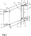
- FIG. 1 shows a radiator 1 with two heating elements 10, 11 and with a valve set 2.
- the valve set 2 is arranged in the lateral region of the radiator. It comprises a flow connection 20 and a return connection 21. Furthermore, it has a first flow line 22, which extends from the flow connection 20 to a valve housing 23.
- the valve housing accommodates a control or valve device in the form of, for example, a thermostatic valve 3. This is in FIG. 1 merely hinted, however, in the FIGS. 7 to 10 better to recognize.
- the valve housing 23 is arranged between the two heating elements 10, 11 in the right lateral upper end region of the radiator.
- the valve housing is open in the direction of the first room side heating element 10, ie provided with an open opening 123 so that heating medium through the first supply line 20 into the valve housing and the thermostat valve 3 and from there into the first heating element 10 can get to this heat. This is in FIG. 1 indicated by the dashed path P1 as the primary flow of the heating medium.
- the valve housing 23 is closed in the direction of the second wall-side heating element 11 in the opening 124 provided there, so that heating medium from the flow via the first flow line 22 through the valve housing 23 can pass into the first heating element 10.
- a second flow line 24 is provided.
- the second supply line 24 extends from the valve housing 23 with respect to the radiator 1 down and opens into a distributor 4 and a manifold block.
- the distributor 4 extends approximately below the valve housing 23 and has four outlet openings 40, 41, 42, 43.
- the first outlet opening 40 points in the direction of the second heating element 11, the second outlet opening 41 in the direction of the first heating element 10, the third outlet opening 42 is formed as a drain opening and the fourth outlet opening 43 is the outlet opening of the return port 21. All these openings 40 to 43 are open, so that via the second flow line 24th introduced into the distribution piece 4 heating medium can pass through the outlet opening 40 into the second heating element 11.
- the heating medium from the flow first rises above the first flow line 22 upwards, the heating medium to reach the second heating element 11 against the physical Direction of flow with the heating of the first heating element 10 are deflected from top to bottom, to pass through the second flow line 24 into the second heating element 11 can.
- the flow of the heating medium through the second supply line 24 into the second heating element 11 and from this also back into the first heating element 10, from which a return of the heating medium takes place in the return is in FIG. 1 and the following figures referred to as secondary flow P2 and is indicated by dotted lines.
- This is arranged in the lower lateral corner region of the radiator opposite to the distribution piece 4. It has two open openings 50, 51 toward the two heating elements 10, 11.
- a lockable connector 6 between the heating elements 10, 11 is arranged. This serves primarily to bleed the two heating elements 10, 11.
- the lockable connector 6 is formed as a T-piece and correspondingly has a branch pipe 60, in which a vent valve can be used (see FIGS. 7 and 9 ).
- the openings 62, 63 are provided open.
- the path from one heating element to the other with respect to a heating medium flow can be sealed off.
- a shut-off in the usual heating operation of the radiator. At least for venting the two heating elements, the lockable connector 6 is opened.
- the usual way of returning heating medium from the second heating element 11 into the first heating element 10 is through the connecting tee 5 in the lower region of the heating element.
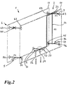
- FIG. 2 radiator shown schematically differs in terms of the valve set 2 in that here a center port is provided instead of a lateral connection of flow and return.
- a first supply line 25 in turn extends from a flow connection 26 to the valve housing 23.
- the flow heating medium again enters the first heating element 10, as indicated by the primary flow P1.
- the way out of the valve housing 23 into the second heating element 11 is the same as in the embodiment according to FIG. 1 blocked.
- fitting 44 which does not include the return port in contrast to the manifold 4, but similar to the valve housing 23 is constructed, wherein the However, only one outlet opening 45 in the direction of the second heating element 11 is open, and an outlet opening 46 in the direction of the first Heating element 10 is closed. Also, the fitting 44 has a discharge opening 47.
- the heating medium in the first heating element 10 passes through the connecting tee 5.
- a connector 7 which includes the return port 27 and also the flow connection 26.
- the connecting piece 7 is arranged between the two heating elements 10, 11 and has an open opening 70 in the direction of the first heating element 10.
- the opening 71 in the direction of the second heating element 11, however, is closed. Thus, heating medium can only get from the first heating element in the return port 27.
- the incoming from the flow heating medium also penetrates the connector 7, the first flow line 25 thus penetrates the connector 7 and extends further in the direction of the valve housing 23.
- the paths of the flow and the return of the heating medium are in the connector 7, however, separated from each other, which in FIG. 2 is merely indicated.
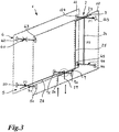
- connection tee 5 is opposite to the embodiment in FIG. 1 and 2 modified so that extends from this to the return port 27 in the connecting piece 7, a return line 28.
- This is conductively connected both to the return port 27 and to the connecting tee 5, so that a heating medium return from both the first heating element 10, which is indicated by the corresponding dashed arrow P1, and from the second heating element 11, the is indicated by the dotted arrow P2, can be carried by the return line 28 to the return port 27.
- the opening 70 of the connector 7 is accordingly closed, as through this opening in the embodiment according to FIG. 3 no heating medium return.
- a heating medium return from both heating elements 10, 11 is provided in the return line 28.
- a separation of the return line 28 and the first flow line 25 is provided in the region of the connecting piece 7 to the effect that an offset, so a spacing, is provided here, which allows easy separation of the line paths.
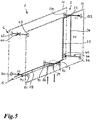
- the embodiment according to FIG. 5 also a lateral offset of the first flow line 25 and the return line 28, wherein these are past each other in a reverse arrangement to each other, again in the connector 7. This illustrates that there are various possibilities to the first flow line 25 and the return line 28 in the region of the connector 7 to separate from each other.
- FIG. 6 a center connection of flow and return with respect to the radiator 1 is provided. Unlike the embodiment in FIG. 2 extends a return line 29 now from the connector 144 to the return port 27. It is again provided in this embodiment, only a Schumediumschreib arrangement from the first heating element 10 in the return port 27.
- the heating medium optionally introduced into the second heating element 11 first passes through the connecting tee 5 from the second heating element 11 into the first heating element 10 and through the distributor 144 or its opening 145 directed in the direction of the first heating element 10 into the return line 29 and the return port 27.
- the second supply line 24 and the return line 29 are separated from one another, ie corresponding channels are formed within the distributing piece 144 in order to allow a line separation here.
- the distributor 144 In the direction of the second heating element 11, the distributor 144 has an open opening 146 for introducing the heating medium.
- the distribution piece 144 further has an emptying opening 147.
- feed connection 26 and return connection 27 can be designed as connection parts which are mechanically connected to one another, which can be determined by the connection loop in FIG. 6 is indicated.
- individual lines can also be formed here in the form of the first supply line 25 and the return line 29 with a corresponding feed end 26 and return connection 27 provided at the end.
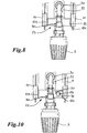
- FIGS. 7 and 9 each show a perspective view of the radiator 1 shown broken in principle in the training according to FIG. 1 , where the in FIG. 1 only schematically indicated lines are now made concrete.
- FIG. 9 is a respect to the positioning of the second flow line 24 with respect to the FIG. 7 modified embodiment of the radiator 1 and the valve assembly 2 shown.
- a lateral fluid discharge opening 30 is formed inside the valve housing 23. Through this, the heating medium which has flowed through the first supply line 22 passes through the outlet opening 123 into the first heating element 10.
- the second flow line 24 extends in the training after FIG. 9 between the valve housing 23 and the distribution piece 4, arranged on the valve housing 23 laterally offset to the discharge point of the first supply line 22.
- a disk element 32 in the outlet opening 124 prevents direct entry of heating medium into the second heating element 11 in this upper region of the heating element 1, as in FIG. 10 indicated.
- a diaphragm or reducing element can be arranged, whereby a limitation of the fluid flow is possible.
- fluid or heating medium firstly enters the first heating element 10, since it follows the path of the lower resistance, and only subsequently into the second heating element 11.
- the volume flow can be kept low, so that the one heating element always flowed first.
- the second flow line 24 extends in the central region of the valve housing 23 and distributor 4 between them.
- the heating medium passes from the supply via the first supply line 22 through the lateral outflow opening 30 of the thermostatic valve 3 in each case initially via the outlet opening 123 in the first heating element 10.
- the heating medium deflected from its upper position downwards against the physical flow direction and thereby passes into the second flow line 24 and through this and the outlet opening 40 into the second heating element 11 inside.
- radiators and valve fittings described in the foregoing and shown in the figures for connecting flow and return of a heating circuit to a radiator with at least two heating elements numerous others can be formed, in each case a first flow line for supplying heating medium to a Ventilumhausung is provided and additionally a second flow line to direct heating medium from the valve housing to the second or further heating element.
Landscapes
- Engineering & Computer Science (AREA)
- Physics & Mathematics (AREA)
- Thermal Sciences (AREA)
- Mechanical Engineering (AREA)
- General Engineering & Computer Science (AREA)
- Chemical & Material Sciences (AREA)
- Combustion & Propulsion (AREA)
- Steam Or Hot-Water Central Heating Systems (AREA)
- Details Of Valves (AREA)
Abstract
Description
Die Erfindung betrifft eine Ventilgarnitur zum Anschluss von Vor- und Rücklauf eines Heizungskreislaufs an einen Heizkörper mit zumindest zwei Heizelementen, wobei die Ventilgarnitur zumindest eine Ventilumhausung zur Aufnahme zumindest einer Stell- oder Ventileinrichtung aufweist, eine erste Vorlaufleitung vorgesehen ist zum Zuführen von Heizmedium zu der Ventilumhausung und zu der in der Ventilumhausung aufnehmbaren oder aufgenommenen Stell- oder Ventileinrichtung, insbesondere einem Thermostat- oder Regelventil, sowie einen asymmetrisch angeströmten oder anströmbaren Heizkörper mit zumindest zwei Heizelementen mit Vorlaufanschluss und Rücklaufanschluss.The invention relates to a valve set for connecting flow and return of a heating circuit to a radiator having at least two heating elements, the valve set having at least one Ventilumhausung for receiving at least one actuating or valve means, a first flow line is provided for supplying heating medium to the valve housing and to the in the Ventilumhausung recordable or accommodated control or valve device, in particular a thermostatic or control valve, and an asymmetrically flowing or vorströmbaren radiator with at least two heating elements with flow connection and return port.
Heizkörper und Ventilgarnituren für diese sind im Stand der Technik vielfältig bekannt. Bei insbesondere Flachheizkörpern mit zumindest zwei Heizplatten bzw. Heizelementen kann über die besondere Führung des Heizmediums, insbesondere erhitzten Wassers, zunächst die vordere zu einem zu beheizenden Raum hin gerichtete Heizplatte/Heizelement von dem Heizmedium durchströmt werden und erst danach die zweite hintere Heizplatte bzw. das hintere Heizelement, die/das von dem zu beheizenden Raum weg, z.B. zu einer Raumwand hin gerichtet ist. Es werden dabei alle zu dem Heizkörper gehörenden Heizelemente bzw. Heizplatten von dem Heizmedium im Kreislauf zwischen Wärmequelle, also einem Heizkessel, und Wärmetauscher, also dem Heizkörper, durchströmt.Radiators and valve fittings for these are widely known in the art. In particular flat radiators with at least two heating plates or heating elements can be flowed through the special leadership of the heating medium, in particular heated water, first the front to a heated space directed heating plate / heating element of the heating medium and only then the second rear heating plate or rear heating element, the / away from the room to be heated, eg is directed towards a room wall. All the heating elements or heating plates belonging to the heating element are thereby flowed through by the heating medium in the circuit between the heat source, that is to say a heating boiler, and the heat exchanger, that is to say the heating element.
Die
Die
Der vorliegenden Erfindung liegt nun die Aufgabe zugrunde, eine Ventilgarnitur zum Anschluss von Vor- und Rücklauf eines Heizungskreislaufs an einen asymmetrisch anströmbaren oder angeströmten Heizkörper mit zumindest zwei Heizelementen sowie einen solchen Heizkörper dahingehend fortzubilden, dass die Effizienz des Heizkörpers in verschiedenen Lastzuständen des Heizkörpers, insbesondere einem schwankenden Heizbedarf, verbessert werden kann, ohne das Vorsehen komplizierter Ventillösungen.The present invention is based on the object, a valve assembly for connecting flow and return of a heating circuit to an asymmetrically approachable or impinged radiator with at least two heating elements and such a radiator to the effect that the efficiency of the radiator in different load conditions of the radiator, in particular a fluctuating heating demand, can be improved without the provision of complicated valve solutions.
Die Aufgabe wird durch eine Ventilgarnitur nach dem Oberbegriff des Anspruchs 1 dadurch gelöst, dass eine zweite Vorlaufleitung vorgesehen und mit der Ventilumhausung verbunden ist, wobei die zweite Vorlaufleitung zum Zuleiten eines Teilstroms des Heizmediums von der Ventilumhausung zu einer dieser von der Höhe her weiter unten angeordneten Einleitstelle in das zweite oder weitere Heizelement ausgebildet ist. Für einen asymmetrisch angeströmten oder anströmbaren Heizkörper nach dem Oberbegriff des Anspruchs 10 wird die Aufgabe dadurch gelöst, dass zumindest eine solche Ventilgarnitur vorgesehen ist, wobei eine Ventilumhausung in einem oberen Bereich des Heizkörpers angeordnet und mit einer ersten Vorlaufleitung und mit zumindest dem ersten Heizelement strömungsverbindbar oder strömungsverbunden ist und eine zweite Vorlaufleitung mit dem zweiten oder weiteren Heizelement in einem unteren Bereich des Heizelements strömungsverbunden ist. Weiterbildungen der Erfindung sind in den abhängigen Ansprüchen definiert.The object is achieved by a valve assembly according to the preamble of
Dadurch wird eine Ventilgarnitur geschaffen, die es ermöglicht, auf eine komplizierte Ventillösung zum Einleiten von Heizmedium zunächst in das erste Heizelement und erst danach in das zweite oder weitere Heizelement zu verzichten, sondern vielmehr eine einfache und zugleich höchst wirkungsvolle Maßnahme vorzusehen, um eine selektive Erwärmung der Heizelemente zu erzielen. Hierbei wird durch das Vorsehen von zwei Vorlaufleitungen eine Art Thermosiphon ausgebildet, bei dem das Heizmedium zum Erreichen des zweiten oder weiteren Heizelements entgegen der physikalischen Strömungsrichtung mit der Erwärmung des ersten Heizelements bezüglich des eingebauten Heizkörpers von oben nach unten abgelenkt wird. Das zu einem Raum gerichtete Heizelement wird dadurch zunächst mit Heizmedium versorgt, das durch die erste Vorlaufleitung in dieses einströmt. Das oder die zumeist zu einer Wand gerichtete(n) oder dahinter angeordnete(n) zweite/weiteren Heizelement(e) wird/werden erst danach mit Heizmedium versorgt. Es ist dadurch möglich, in einem Teillastbetrieb lediglich das erste Heizelement und bei geringeren Außentemperaturen und somit Volllastbetrieb auch das zumindest eine weitere Heizelement zu erwärmen.As a result, a valve set is created, which makes it possible to dispense with a complicated valve solution for introducing heating medium first in the first heating element and only then in the second or further heating element, but rather to provide a simple and at the same time highly effective measure to a selective heating to achieve the heating elements. In this case, by providing two flow lines, a type of thermosyphon is formed in which the heating medium is deflected from top to bottom against the physical flow direction with the heating of the first heating element with respect to the installed radiator to reach the second or further heating element. The directed to a room heating element is thus initially supplied with heating medium, which flows through the first flow line in this. The second or further heating element (s), which is usually directed towards a wall or arranged behind it, is / are only then supplied with heating medium. It is thereby possible, in a partial load operation, to heat only the first heating element and, at lower outside temperatures and thus full load operation, also the at least one further heating element.
Mit der Ventilumhausung sind beide Vorlaufleitungen verbunden und die Ventilumhausung ist in Bezug auf den Heizkörper in dessen oberen Bereich zumeist zwischen zwei benachbarten Heizelementen angeordnet. Die erste Vorlaufleitung erstreckt sich von dem bodenseitigen Vorlaufanschluss nach oben zu der Ventilumhausung und die zweite Vorlaufleitung wiederum nach unten, um ein Einleiten von Heizmedium im unteren Bereich des zweiten oder weiteren Heizelements in dieses zu ermöglichen. Vorteilhaft ist die Ventilumhausung in einem oberen seitlichen Bereich des Heizkörpers angeordnet, um eine einfache Betätigung der Stell- oder Ventileinrichtung in Form eines Thermostatventils oder eines anderweitigen Regelventils oder einer Steuereinrichtung zu ermöglichen.With the Ventilumhausung both supply lines are connected and the Ventilumhausung is arranged with respect to the radiator in the upper region mostly between two adjacent heating elements. The first flow line extends from the bottom-side flow connection up to the valve housing and the second flow line in turn down to allow introduction of heating medium in the lower region of the second or further heating element in this. Advantageously, the valve housing is arranged in an upper lateral region of the radiator in order to enable a simple actuation of the control or valve device in the form of a thermostatic valve or another control valve or a control device.
Vorteilhaft ist ein Verteilstück oder Verteilerblock vorgesehen, das oder der zum Vorsehen eines Rücklaufanschlusses für zumindest eines der Heizelemente, insbesondere das erste Heizelement, mit diesem leitungsoffen verbindbar und mit der zweiten Vorlaufleitung verbindbar oder verbunden ist. Das Verteilstück ist vorteilhaft auf derselben Seite wie die Ventilumhausung, jedoch unterhalb von dieser, insbesondere in einem unteren Eckbereich des Heizkörpers, angeordnet. Durch das Verteilstück werden vorteilhaft die beiden benachbarten Heizelemente in einem gewünschten Abstand zueinander verbunden. Die zweite Vorlaufleitung ist mit dem Verteilstück verbunden, kann mit diesem in Strömungsverbindung stehen, muss dies jedoch nicht. Sie kann also in das Verteilstück münden, so dass das Heizmedium vor dem Eintritt in das weitere Heizelement zunächst durch einen hierfür ausgebildeten Teil des Verteilstücks strömt. Es ist jedoch grundsätzlich ebenfalls möglich, dass die zweite Vorlaufleitung lediglich mechanisch mit dem Verteilstück verbunden ist und direkt in das zweite Heizelement mündet, wobei diese Ausführungsvariante nicht bevorzugt wird.Advantageously, a distributor or distributor block is provided, which or for providing a return connection for at least one of the heating elements, in particular the first heating element, can be connected to the latter and connected to the second supply line or connected. The distributor is advantageously arranged on the same side as the valve housing, but below it, in particular in a lower corner region of the radiator. By the distributor advantageously the two adjacent heating elements are connected at a desired distance from each other. The second supply line is connected to the distributor, can be in fluid communication with this, but this need not. It can therefore open into the distribution piece, so that the heating medium first flows through a trained part of the distribution piece before entering the further heating element. However, it is also possible in principle that the second flow line is only mechanically connected to the distribution piece and opens directly into the second heating element, this embodiment is not preferred.
Das Verteilstück weist vorteilhaft zumindest zwei voneinander getrennte Kammern oder Kanäle auf, von denen ein erster Kanal zum Einleiten von Heizmedium in das zweite oder weitere Heizelement und ein zweiter Kanal zum Leiten von Heizmedium in den Rücklauf, insbesondere von Heizmedium aus dem ersten Heizelement in den Rücklauf, vorgesehen ist. Durch diese zumindest zweikanalige Ausbildung ist auf einfache Weise eine optimale Trennung der beiden Wege, des Hinwegs und des Rückwegs, des Heizmediums von dem Vorlauf in das zweite oder weitere Heizelement und aus dem ersten Heizelement in den Rücklauf möglich. Das Einströmen von Heizmedium aus dem Vorlauf in das erste Heizelement erfolgt über die erste Vorlaufleitung und die Ventilumhausung, die räumlich betrachtet zumeist oberhalb des Verteilstücks angeordnet ist.The distribution piece advantageously has at least two separate chambers or channels, of which a first channel for introducing heating medium into the second or further heating element and a second channel for conducting heating medium in the return, in particular heating medium from the first heating element in the return , is provided. This at least two-channel design is a simple way of optimal separation of the two ways, the way and the return, the heating medium of the flow in the second or further heating element and from the first heating element in the return possible. The inflow of heating medium from the flow in the first heating element via the first flow line and the valve housing, which is spatially seen mostly located above the distribution piece.
Mündet die zweite Vorlaufleitung in das Verteilstück, ist vorteilhaft der erste Kanal des Verteilstücks mit der zweiten Vorlaufleitung strömungsverbunden, so dass das Heizmedium durch diesen ersten Kanal in das zweite oder weitere Heizelement einströmt.If the second supply line opens into the distributing piece, the first channel of the distributing piece is advantageously flow-connected to the second supply line, so that the heating medium flows through this first channel into the second or further heating element.
Das Verteilstück kann eine Rücklauföffnung für den Rücklauf von Heizmedium und eine Entleerungsöffnung zum Entleeren des Heizkörpers aufweisen. Es ist somit neben dem Rückführen des Heizmediums in den Rücklauf auch ein vollständiges Entleeren des Heizkörpers durch die Entleerungsöffnung möglich.The distributor may have a return opening for the return of heating medium and a discharge opening for emptying the radiator. It is thus possible in addition to the return of the heating medium in the return and a complete emptying of the radiator through the discharge opening.
Die Ausbildung der Kanäle innerhalb des Verteilstücks kann auf verschiedene Arten erfolgen. Insbesondere ist es möglich, das Verteilstück zum Ausbilden der Kanäle in seinem mittleren Bereich massiv auszubilden und mit Kanalbohrungen zu versehen. Das Verteilstück kann dabei zumindest in seinem mittleren Bereich aus Metall, insbesondere Stahl, bestehen, also auf diese Weise massiv ausgebildet sein. Die Kanalbohrungen können durch ein Bohrwerkzeug oder auf andere geeignete Weise in das massive Material eingebracht werden.The formation of the channels within the distribution can be done in various ways. In particular, it is possible to form the distribution piece for forming the channels in its central region solid and provided with channel holes. The distribution piece can be made of metal, in particular steel, at least in its middle region, that is to say be solid in this way. The channel bores may be introduced into the solid material by a drilling tool or other suitable means.
Ferner ist es möglich, dass das Verteilstück zum Ausbilden der Kanäle mit einem Einschubteil versehen ist, das mit gegeneinander abgetrennten Kanälen oder Kammern versehen ist oder solche ausbildet. Das Verteilstück ist dabei als Hohlteil ausgebildet und mit dem Einschubteil versehen. Das Einschubteil kann ein festes oder flexibles Teil sein und wird in das Hohlteil eingeschoben oder eingebracht. Vorteilhaft legt sich das Einschubteil dicht schließend an die Wandungen des Verteilstücks an. Hierdurch entsteht eine dichte Einheit, die die gewünschten voneinander getrennten Kanäle zum getrennten Leiten des Heizmediums von dem Vorlauf zu dem zweiten oder weiteren Heizelement und von dem ersten Heizelement in den Rücklauf zulässt.Further, it is possible that the distribution piece for forming the channels is provided with an insertion part which is provided with or formed with mutually separated channels or chambers. The distributor is designed as a hollow part and provided with the insertion part. The insertion part may be a fixed or flexible part and is inserted or inserted into the hollow part. Advantageously, the insertion part places tightly against the walls of the distribution piece. This creates a sealed unit that allows the desired separate channels for separately directing the heating medium from the flow to the second or further heating element and from the first heating element in the return.
Ferner kann das Verteilstück zum Ausbilden der Kanäle eine Masse aufweisen, die mit Kanälen versehen wird oder ist. Die Kanäle können in die Masse während deren Einbringungsprozess oder nach deren Aushärtung eingebracht werden. Das Verteilstück selbst ist vorteilhaft wiederum als Hohlteil ausgebildet, so dass die Masse in das Hohlteil durch Einspritzen, Einpressen oder Eingießen eingebracht sein oder werden kann. Als Masse eignet sich insbesondere eine Kunststoffmasse, so dass bei Vorsehen eines Hohlteils, das zumindest in dem mit der Masse versehenen Bereich aus einem Metall besteht, das Verteilstück als außenseitig Metall- und innseitig Kunststoffteil mit eingebrachten Kanälen ausgebildet ist.Further, the manifold for forming the channels may have a mass that is or is provided with channels. The channels can be introduced into the mass during their introduction process or after their hardening. The distribution piece itself is advantageously again designed as a hollow part, so that the mass can be introduced into the hollow part by injection, injection or pouring or can be. In particular, a plastic compound is suitable as a mass, so that when providing a hollow part, which consists of a metal at least in the area provided with the mass, the distribution piece is designed as an outside metal and innseitig plastic part with introduced channels.
Als besonders vorteilhaft erweist es sich, den Rücklaufanschluss an das erste Heizelement anzuschließen. Strömt Heizmedium außer in das erste Heizelement auch in das zweite oder weitere Heizelement ein, kann dieses aus dem zweiten oder weiteren Heizelement in das erste Heizelement und von dort über den Rücklaufanschluss in den Rücklauf geleitet werden. Ebenfalls ist es möglich, eine Rückführung von Heizmedium aus dem ersten und den zweiten oder weiteren Heizelement über eine Rücklaufleitung vorzusehen. Eine solche Rücklaufleitung ist dabei vorteilhaft an ein die beiden benachbarten Heizelemente miteinander verbindendes Verteil- und/oder Anschlussstück angeschlossen. Aus den beiden Heizelementen gelangt das rückströmende Heizmedium in das Verteil- und/oder Anschlussstück und von diesem über die Rücklaufleitung zu dem Rücklaufanschluss, wobei sich die Rücklaufleitung zwischen dem Verteil-und/oder Anschlussstück und dem Rücklaufanschluss erstreckt.It proves to be particularly advantageous to connect the return connection to the first heating element. If heating medium flows into the second or further heating element in addition to the first heating element, this can be conducted from the second or further heating element into the first heating element and from there via the return connection into the return flow. It is also possible to provide a return of heating medium from the first and the second or further heating element via a return line. Such a return line is advantageously connected to a two adjacent heating elements interconnecting distribution and / or connection piece. From the two heating elements, the back-flowing heating medium enters the distribution and / or connection piece and from there via the return line to the return connection, wherein the return line extends between the distribution and / or connection piece and the return connection.
Der Vorlaufanschluss und der Rücklaufanschluss können seitlich bezüglich des Heizkörpers anordbar oder angeordnet sein. Ferner ist es möglich, den Vorlaufanschluss und den Rücklaufanschluss mittig bezüglich des Heizkörpers anzuordnen. Gerade bei dieser Variante ergeben sich verschiedene Möglichkeiten bezüglich der Rückführung des Heizmediums zum Rücklauf sowie der Positionierung der ersten Vorlaufleitung und der Rücklaufleitung zueinander. In einer ersten Möglichkeit kann die erste Vorlaufleitung mit dem Vorlaufanschluss verbunden und zu der Seite des Heizkörpers geführt sein, an der die Ventilumhausung angeordnet ist. Der Rücklaufanschluss ist mittig an dem ersten Heizelement angeschlossen und von dem zweiten oder weiteren Heizelement(en) wird Heizmedium über eine Leitung oder das verbindende Verteil- und/oder Anschlussstück zu dem ersten Heizelement zurückgeführt, so dass der gesamte Rücklauf immer aus dem ersten Heizelement vorgesehen ist.The flow connection and the return connection can be arranged or arranged laterally relative to the radiator. Furthermore, it is possible to arrange the flow connection and the return connection centrally with respect to the radiator. Especially in this variant, various possibilities arise with respect to the return of the heating medium to the return and the positioning of the first flow line and the return line to each other. In a first possibility, the first supply line can be connected to the flow connection and guided to the side of the radiator on which the valve housing is arranged. The return port is centrally connected to the first heating element and from the second or further heating element (s) heating medium is returned via a line or the connecting distribution and / or connecting piece to the first heating element, so that the entire return always provided from the first heating element is.
In einer zweiten Möglichkeit sind die erste Vorlaufleitung und die Rücklaufleitung zumindest im Bereich von Vorlauf- und Rücklaufanschluss versetzt zueinander angeordnet und mit diesem verbunden. Die Rücklaufleitung erstreckt sich dabei, wie vorstehend bereits beschrieben, von dem verbindenden Verteil- und/oder Anschlussstück zu dem Rücklaufanschluss. Die erste Vorlaufleitung und die Rücklaufleitung können im Bereich von Vorlauf- und Rücklaufanschluss auch einander durchquerend oder durchdringend vorgesehen sein, wobei die eine Leitung sich durch die andere hindurch erstreckt, wobei keine fluidische bzw. Strömungsverbindung des in beiden Leitungen strömenden Heizmediums vorgesehen ist.In a second possibility, the first supply line and the return line are arranged at least in the region of supply and return connection offset from one another and connected thereto. The return line extends, as already described above, from the connecting distributor and / or connector to the return port. The first supply line and the Return line may be provided in the region of flow and return port also crossing or penetrating each other, wherein the one line extends through the other, wherein no fluidic or flow connection of the flowing in both lines heating medium is provided.
Die Rücklaufleitung kann sich von einem zwei benachbarte Heizelemente verbindenden Verteil- und/oder Anschlussstück, das auf der Seite der Ventilumhausung angeordnet ist, allerdings räumlich unterhalb von diesem, zu dem Rücklaufanschluss erstrecken. Auch hierbei können die erste Vorlaufleitung und die Rücklaufleitung versetzt zueinander angeordnet sein. Das verbindende Verteil- und/oder Anschlussstück weist vorteilhaft die bereits vorstehend genannten zumindest zwei getrennten Kanäle oder Kammern zum Trennen des rückströmenden Heizmediums aus dem ersten Heizelement von dem dem zweiten oder weiteren Heizelement zugeleiteten Heizmedium auf.The return line may extend from a two adjacent heating elements connecting distribution and / or fitting, which is arranged on the side of the valve housing, but spatially below this, to the return port. Again, the first flow line and the return line can be arranged offset from each other. The connecting distributor and / or connecting piece advantageously has the above-mentioned at least two separate channels or chambers for separating the back-flowing heating medium from the first heating element from the heating medium fed to the second or further heating element.
Zum Entlüften der Heizelemente ist vorteilhaft ein absperrbares Verbindungsstück mit zumindest einem Abzweigstutzen zwischen den zumindest zwei Heizelementen im oberen Bereich mit Abstand zu der Ventilumhausung angeordnet. Das Verbindungsstück ist beispielsweise als T-Stück ausgebildet. Der Abzweigstutzen weist die Entlüftungsöffnung zum Entlüften auf. Das Verbindungsstück ist endseitig offen ausgebildet und mit den beiden an dieses angrenzenden und mit diesem verbundenen Heizelementen strömungsverbunden. Durch die Möglichkeit eines Absperrens, also Schließens, und Öffnens kann über das Verbindungsstück ein Entlüften aller Heizelemente erfolgen, wenn dies gewünscht wird, und ansonsten die Verbindung zwischen den Heizelementen in diesem Bereich vollständig geschlossen werden, so dass an dieser Stelle kein Heizmedium von dem einen in das andere Heizelement gelangen kann. Ist die Ventilumhausung in einem oberen seitlichen Endbereich des Heizkörpers angeordnet, ist das Verbindungsstück bevorzugt in dem gegenüberliegenden oberen seitlichen Endbereich des Heizkörpers angeordnet.For venting the heating elements is advantageously a lockable connector with at least one branch pipe between the at least two heating elements in the upper region arranged at a distance from the valve housing. The connecting piece is designed for example as a T-piece. The branch piece has the vent for venting. The connector is open at the end and connected to the two adjacent thereto and connected to this heating elements. By the possibility of shut-off, so closing, and opening can be done via the connector venting all heating elements, if desired, and otherwise the connection between the heating elements in this area are completely closed, so that at this point no heating medium of the one can get into the other heating element. If the valve housing is arranged in an upper lateral end region of the radiator, the connecting piece is preferably arranged in the opposite upper side end region of the radiator.
Zur näheren Erläuterung der Erfindung wird diese im Folgenden näher anhand der Zeichnungen beschrieben. Diese zeigen in:
Figur 1- eine perspektivische schematische Ansicht eines erfindungsgemäßen Heizkörpers mit seitlich angeordnetem Vorlauf- und Rücklaufanschluss und mit einer erfindungsgemäßen Ventilgarnitur,
Figur 2- eine perspektivische schematische Ansicht eines erfindungsgemäßen Heizkörpers mit mittig angeordnetem Vorlauf- und Rücklaufanschluss und mit einer erfindungsgemäßen Ventilgarnitur in einer zweiten Ausführungsform,
Figur 3- eine perspektivische schematische Ansicht eines erfindungsgemäßen Heizkörpers mit mittig angeordnetem Vorlauf- und Rücklaufanschluss und mit einer erfindungsgemäßen Ventilgarnitur in einer dritten Ausführungsform, die eine sich von einem Verbindungsstück zum Rücklaufanschluss erstreckende Rücklaufleitung umfasst,
Figur 4- eine perspektivische schematische Ansicht eines erfindungsgemäßen Heizkörpers mit mittig angeordnetem Vorlauf- und Rücklaufanschluss und mit einer erfindungsgemäßen Ventilgarnitur in einer vierten Ausführungsform, die eine sich von einem Verbindungsstück zum Rücklaufanschluss erstreckende Rücklaufleitung umfasst,
Figur 5- eine perspektivische schematische Ansicht eines erfindungsgemäßen Heizkörpers mit mittig angeordnetem Vorlauf- und Rücklaufanschluss und mit einer erfindungsgemäßen Ventilgarnitur in einer fünften Ausführungsform, die eine sich von einem Verbindungsstück zum Rücklaufanschluss erstreckende Rücklaufleitung umfasst,
Figur 6- eine perspektivische schematische Ansicht eines erfindungsgemäßen Heizkörpers mit mittig angeordnetem Vorlauf- und Rücklaufanschluss und mit einer erfindungsgemäßen Ventilgarnitur in einer sechsten Ausführungsform, die eine sich von einem Verteilstück zum Rücklaufanschluss erstreckende Rücklaufleitung umfasst,
Figur 7- eine perspektivische Ansicht eines erfindungsgemäßen Heizkörpers mit einer erfindungsgemäßen Ventilgarnitur in einer siebten Ausführungsform,
- Figur 8
- eine Draufsicht auf den
Heizkörper gemäß Figur 7 im Bereich des Details der Ventilumhausung mit Thermostatventil, - Figur 9
- eine perspektivische Ansicht eines erfindungsgemäßen Heizkörpers mit einer erfindungsgemäßen Ventilgarnitur in einer achten Ausführungsform, und
Figur 10- eine Draufsicht auf den Heizkörper gemäß
Figur 9 im Bereich des Details der Ventilumhausung mit Thermostatventil.
- FIG. 1
- a perspective schematic view of a radiator according to the invention with laterally arranged flow and return connection and with a valve assembly according to the invention,
- FIG. 2
- a perspective schematic view of a radiator according to the invention with centrally arranged flow and return port and with a valve assembly according to the invention in a second embodiment,
- FIG. 3
- a perspective schematic view of a radiator according to the invention with centrally arranged flow and return port and with a valve assembly according to the invention in a third embodiment, which comprises a from a connector to the return port extending return line,
- FIG. 4
- a perspective schematic view of a radiator according to the invention with centrally arranged flow and return port and with a valve assembly according to the invention in a fourth embodiment, which comprises a from a connector to the return port extending return line,
- FIG. 5
- a perspective schematic view of a radiator according to the invention with centrally arranged flow and return port and with a valve assembly according to the invention in a fifth embodiment, which comprises a from a connector to the return port extending return line,
- FIG. 6
- a perspective schematic view of a radiator according to the invention with centrally arranged flow and return port and with a valve assembly according to the invention in a sixth embodiment, which comprises a from a distributor to the return port extending return line,
- FIG. 7
- a perspective view of a radiator according to the invention with a valve assembly according to the invention in a seventh embodiment,
- FIG. 8
- a plan view of the radiator according to
FIG. 7 in the area of the detail of the valve housing with thermostatic valve, - FIG. 9
- a perspective view of a radiator according to the invention with a valve assembly according to the invention in an eighth embodiment, and
- FIG. 10
- a plan view of the radiator according to
FIG. 9 in the area of the detail of the valve housing with thermostatic valve.
Die Ventilumhausung 23 ist zwischen den beiden Heizelementen 10, 11 im rechten seitlichen oberen Endbereich des Heizkörpers angeordnet. Die Ventilumhausung ist leitungsoffen in Richtung des ersten raumseitig angeordneten Heizelements 10, also mit einer offenen Öffnung 123 versehen, so dass Heizmedium durch die erste Vorlaufleitung 20 in die Ventilumhausung und das Thermostatventil 3 und von dort in das erste Heizelement 10 gelangen kann, um dieses zu erwärmen. Dies ist in
Um Heizmedium auch dem zweiten Heizelement 11 zuzuführen, ist eine zweite Vorlaufleitung 24 vorgesehen. Die zweite Vorlaufleitung 24 erstreckt sich von der Ventilumhausung 23 bezüglich des Heizkörpers 1 nach unten und mündet in ein Verteilstück 4 bzw. einen Verteilerblock. Das Verteilstück 4 erstreckt sich etwa unterhalb der Ventilumhausung 23 und weist vier Auslassöffnungen 40, 41, 42, 43 auf. Die erste Auslassöffnung 40 weist in Richtung des zweiten Heizelementes 11, die zweite Auslassöffnung 41 in Richtung des ersten Heizelementes 10, die dritte Auslassöffnung 42 ist als Entleerungsöffnung ausgebildet und die vierte Auslassöffnung 43 ist die Auslassöffnung des Rücklaufanschlusses 21. Alle diese Öffnungen 40 bis 43 stehen offen, so dass das über die zweite Vorlaufleitung 24 in das Verteilstück 4 eingeleitete Heizmedium durch die Auslassöffnung 40 in das zweite Heizelement 11 gelangen kann.In order to supply heating medium and the
Nachdem die Ventilumhausung 23 im oberen seitlichen Endbereich der beiden Heizelemente 10, 11 bzw. des Heizkörpers 1 angeordnet ist, das Heizmedium aus dem Vorlauf zunächst einmal über die erste Vorlaufleitung 22 nach oben aufsteigt, muss das Heizmedium zum Erreichen des zweiten Heizelementes 11 entgegen der physikalischen Strömungsrichtung mit der Erwärmung des erstes Heizelementes 10 von oben nach unten abgelenkt werden, um durch die zweite Vorlaufleitung 24 in das zweite Heizelement 11 gelangen zu können. Die Strömung des Heizmediums durch die zweite Vorlaufleitung 24 hindurch in das zweite Heizelement 11 und aus diesem auch wieder zurück in das erste Heizelement 10, aus dem heraus ein Rückführen des Heizmediums in den Rücklauf erfolgt, wird in
Die Rückströmung des Heizmediums aus dem zweiten Heizelement 11 in das erste Heizelement 10 erfolgt über ein Verbindungs-T-Stück 5. Dieses ist im unteren seitlichen Eckbereich des Heizkörpers gegenüberliegend zu dem Verteilstück 4 angeordnet. Es weist zwei offene Öffnungen 50, 51 zu den beiden Heizelementen 10 ,11 hin auf.The return flow of the heating medium from the
In der über dem Verbindungs-T-Stück 5 angeordneten oberen Ecke des Heizkörpers 1, gegenüberliegend zu der Ventilumhausung 23, ist ein absperrbares Verbindungsstück 6 zwischen den Heizelementen 10, 11 angeordnet. Dieses dient in erster Linie dem Entlüften der beiden Heizelemente 10, 11. Aus diesem Grunde ist das absperrbare Verbindungsstück 6 als T-Stück ausgebildet und weist entsprechend einen Abzweigstutzen 60 auf, in den ein Entlüfttungsventil eingesetzt werden kann (siehe
Durch die Möglichkeit eines Verriegelns oder Absperrens, also Schließens des Verbindungsstücks 6 kann der Weg von dem einen Heizelement in das andere im Hinblick auf eine Heizmediumströmung abgeriegelt werden. Üblicherweise erfolgt ein Absperren im üblichen Heizbetrieb des Heizkörpers. Zumindest zum Entlüften der beiden Heizelemente wird das absperrbare Verbindungsstück 6 geöffnet. Grundsätzlich ist es jedoch möglich, auch zum Zulassen eines Übertritts von Heizmedium aus dem zweiten Heizelement 11 in das erste Heizelement 10, das Verbindungsstück 6 zu öffnen und somit eine Heizmediumströmung zuzulassen. Der übliche Weg des Rücklaufs von Heizmedium aus dem zweiten Heizelement 11 in das erste Heizelement 10 erfolgt jedoch durch das Verbindungs-T-Stück 5 im unteren Bereich des Heizkörpers.Due to the possibility of locking or shut-off, ie closing of the connecting
Um den Heizmediumvorlauf in das zweite Heizelement 11 getrennt von dem Heizmediumrücklauf aus dem ersten Heizelement in ein und demselben Verteilstück 4 unterbringen zu können, ist dieses auf besondere Art und Weise durch Ausbilden verschiedener Kanäle ausgebildet. Dies ist in
Der in
Aus dem zweiten Heizelement 11 gelangt das Heizmedium in das erste Heizelement 10 wiederum durch das Verbindungs-T-Stück 5. Um das rückströmende Heizmedium aus dem ersten Heizelement 10 in den Rücklaufanschluss 27 zu leiten, ist etwa mittig im unteren Bereich des Heizkörpers 1 ein Anschlussstück 7 vorgesehen, das den Rücklaufanschluss 27 und auch den Vorlaufanschluss 26 umfasst. Das Anschlussstück 7 ist zwischen den beiden Heizelementen 10, 11 angeordnet und weist in Richtung des ersten Heizelementes 10 eine offene Öffnung 70 auf. Die Öffnung 71 in Richtung des zweiten Heizelementes 11 ist hingegen verschlossen. Somit kann Heizmedium lediglich aus dem ersten Heizelement in den Rücklaufanschluss 27 gelangen.From the
Das aus dem Vorlauf ankommende Heizmedium durchdringt ebenfalls das Anschlussstück 7, die erste Vorlaufleitung 25 durchdringt also das Anschlussstück 7 und erstreckt sich weiter in Richtung der Ventilumhausung 23. Die Pfade des Vorlaufs und des Rücklaufs des Heizmediums sind in dem Anschlussstück 7 jedoch voneinander getrennt, was in
Bei der Ausführungsform des Heizkörpers gemäß
Wie in
Bei der Ausführungsform gemäß
Im Unterschied zu der Ausführungsform gemäß
Auch in
Im Bereich des mittig angeordneten Vorlaufanschlusses 26 und Rücklaufanschlusses 27 können diese als miteinander mechanisch verbundene Anschlussteile ausgebildet sein, was durch die Verbindungsschlinge in
Die
Die zweite Vorlaufleitung 24 erstreckt sich bei der Ausbildung nach
In der Ventilumhausung 23 kann ein Blenden- oder Reduzierelement angeordnet werden, wodurch eine Begrenzung des Fluidstroms möglich ist. Durch Vorsehen eines Blenden- bzw. Einlegeelements gelangt Fluid bzw. Heizmedium zunächst in das erste Heizelement 10, da es den Weg des geringeren Widerstandes geht, und erst nachfolgend in das zweite Heizelement 11. Der Volumenstrom kann gering gehalten werden, so dass das eine Heizelement stets zuerst angeströmt wird. Dieser Effekt kann zwar bereits durch das Vorsehen der beiden Vorlaufleitungen erzielt werden. Er kann jedoch durch Vorsehen eines Blenden- bzw. Einlegeelements noch unterstützt werden.In the
Bei der Ausführungsform des Heizkörpers, die in
In dem absperrbaren Verbindungsstück 6 ist in den
Neben den im Vorstehenden beschriebenen und in den Figuren gezeigten Ausführungsformen von Heizkörpern und Ventilgarnituren zum Anschluss von Vor- und Rücklauf eines Heizungskreislaufs an einen Heizkörper mit zumindest zwei Heizelementen können noch zahlreiche weitere gebildet werden, bei denen jeweils eine erste Vorlaufleitung zum Zuführen von Heizmedium zu einer Ventilumhausung vorgesehen ist und zusätzlich eine zweite Vorlaufleitung, um Heizmedium von der Ventilumhausung zu dem zweiten oder weiteren Heizelement zu leiten.In addition to the embodiments of radiators and valve fittings described in the foregoing and shown in the figures for connecting flow and return of a heating circuit to a radiator with at least two heating elements, numerous others can be formed, in each case a first flow line for supplying heating medium to a Ventilumhausung is provided and additionally a second flow line to direct heating medium from the valve housing to the second or further heating element.
- 11
- Heizkörperradiator
- 22
- Ventilgarniturvalve set
- 33
- Thermostatventilthermostatic valve
- 44
- Verteilstück/VerteilerblockDistribution piece / distribution block
- 55
- Verbindungs-T-StückConnection Tee
- 66
- absperrbares Verbindungsstücklockable connector
- 77
- Anschlussstückconnector
- 1010
- erstes Heizelement (raumseitig)first heating element (room side)
- 1111
- zweites Heizelement (wandseitig)second heating element (wall side)
- 2020
- VorlaufanschlussFlow connection
- 2121
- RücklaufanschlussReturn connection
- 2222
- erste Vorlaufleitungfirst supply line
- 2323
- VentilumhausungVentilumhausung
- 2424
- zweite Vorlaufleitungsecond supply line
- 2525
- erste Vorlaufleitungfirst supply line
- 2626
- VorlaufanschlussFlow connection
- 2727
- RücklaufanschlussReturn connection
- 2828
- RücklaufleitungReturn line
- 2929
- RücklaufleitungReturn line
- 3030
- seitliche Ausströmöffnunglateral outflow opening
- 3232
- Scheibenelementdisk element
- 4040
- Auslassöffnungoutlet
- 4141
- Auslassöffnungoutlet
- 4242
- Auslassöffnung/EntleerungsöffnungOutlet / discharge opening
- 4343
- Auslassöffnungoutlet
- 4444
- Anschlussstückconnector
- 4545
- Auslassöffnungoutlet
- 4646
- verschlossene Auslassöffnungclosed outlet opening
- 4747
- Entleerungsöffnungemptying opening
- 5050
- Öffnungopening
- 5151
- Öffnungopening
- 6060
- Abzweigstutzen/VerbindungsstückBranch socket / connector
- 6161
- Entlüftungseinrichtungvent
- 6262
- Öffnungopening
- 6363
- Öffnungopening
- 7070
- Öffnungopening
- 7171
- geschlossene Öffnungclosed opening
- 123123
- Auslassöffnungoutlet
- 124124
- Öffnungopening
- 144144
- Verteilstückdistribution piece
- 145145
- Öffnungopening
- 146146
- Öffnungopening
- 147147
- Entleerungsöffnungemptying opening
Claims (15)
dadurch gekennzeichnet, dass
eine zweite Vorlaufleitung (24) vorgesehen und mit der Ventilumhausung (23) verbunden ist, wobei die zweite Vorlaufleitung (24) zum Zuleiten eines Teilstroms des Heizmediums von der Ventilumhausung (23) zu einer dieser von der Höhe her weiter unten angeordneten Einleitstelle (40,45,146) in das zweite oder weitere Heizelement (11) ausgebildet ist.Valve set (2) for connecting supply and return of a heating circuit to a radiator (1) with at least two heating elements (10,11), wherein the valve set (2) at least one Ventilumhausung (23) for receiving at least one control or valve device ( 3), a first supply line (22,25) is provided for supplying heating medium to the valve housing (23) and the in the Ventilumhausung (23) can be accommodated or recorded actuator or valve device, in particular a thermostatic or control valve (3) .
characterized in that
a second supply line (24) is provided and connected to the valve housing (23), wherein the second supply line (24) for supplying a partial flow of the heating medium from the valve housing (23) to one of these from the height down further arranged discharge point (40, 45, 146) is formed in the second or further heating element (11).
dadurch gekennzeichnet, dass
ein Verteilstück (4) vorgesehen ist, das zum Vorsehen eines Rücklaufanschlusses (21) für zumindest eines der Heizelemente (10,11), insbesondere das erste Heizelement, mit diesem leitungsoffen verbindbar und mit der zweiten Vorlaufleitung (24) verbindbar oder verbunden ist und/oder ein Verteil- und/oder Anschlussstück (7) vorgesehen ist, das zum Vorsehen eines Rücklaufanschlusses (27) für zumindest eines der Heizelemente (10,11), insbesondere das erste Heizelement (10), mit diesem leitungsoffen verbindbar oder mit einer Rücklaufleitung (28) verbindbar oder verbunden und mit der ersten Vorlaufleitung (25) verbindbar oder verbunden ist.Valve set (2) according to claim 1,
characterized in that
a distribution piece (4) is provided, which is connectable or connected to at least one of the heating elements (10, 11), in particular the first heating element, can be connected to and connected to the second supply line (24) to provide a return connection (21) and / or or a distribution and / or connecting piece (7) is provided, which for providing a return port (27) for at least one of the heating elements (10,11), in particular the first heating element (10), connectable to this line open or with a return line ( 28) can be connected or connected and connected or connected to the first flow line (25).
dadurch gekennzeichnet, dass
das Verteilstück (4) zumindest zwei voneinander getrennte Kammern oder Kanäle aufweist, von denen ein erster Kanal zum Einleiten von Heizmedium in das zweite oder weitere Heizelement (11) und ein zweiter Kanal zum Leiten von Heizmedium in den Rücklauf, insbesondere von Heizmedium aus dem ersten Heizelement (10) in den Rücklauf, vorgesehen ist.Valve set (2) according to claim 2,
characterized in that
the distribution piece (4) has at least two separate chambers or channels, of which a first channel for introducing heating medium into the second or further heating element (11) and a second channel for conducting heating medium in the return, in particular heating medium from the first Heating element (10) in the return, is provided.
dadurch gekennzeichnet, dass
das Verteilstück (4) eine Rücklauföffnung (43) für den Rücklauf von Heizmedium und eine Entleerungsöffnung (42) zum Entleeren des Heizkörpers aufweist und/oder der erste Kanal des Verteilstücks (4) mit der zweiten Vorlaufleitung (24) strömungsverbunden ist.Valve set (2) according to claim 2 or 3,
characterized in that
the distribution piece (4) has a return opening (43) for the return of heating medium and an emptying opening (42) for emptying the heating element and / or the first channel of the distributing piece (4) is flow-connected to the second supply line (24).
dadurch gekennzeichnet, dass
das Verteil- und/oder Anschlussstück (7) zumindest zwei voneinander getrennte Kammern oder Kanäle aufweist zum Trennen der ersten Vorlaufleitung (25) von dem Heizmedium-Rücklauf.Valve set (2) according to claim 2,
characterized in that
the distribution and / or connecting piece (7) has at least two separate chambers or channels for separating the first supply line (25) from the heating medium return line.
dadurch gekennzeichnet, dass
das Verteil- oder Verteil- und/oder Anschlussstück (4,7) zum Ausbilden der Kanäle in seinem mittleren Bereich massiv ausbildet und mit Kanalbohrungen versehen ist.Valve set (2) according to one of claims 3 to 5,
characterized in that
the distribution or distribution and / or fitting (4,7) for forming the channels in its central region massively formed and is provided with channel holes.
dadurch gekennzeichnet, dass
das Verteil- oder Verteil- und/oder Anschlussstück (4,7) zumindest in seinem mittleren Bereich aus Metall, insbesondere Stahl, besteht.Valve set (2) according to one of claims 2 to 6,
characterized in that
the distribution or distribution and / or connecting piece (4,7) at least in its central region of metal, in particular steel.
dadurch gekennzeichnet, dass
das Verteil- oder Verteil- und/oder Anschlussstück (4,7) zum Ausbilden der Kanäle mit einem Einschubteil versehen ist, das mit gegeneinander abgetrennten Kanälen oder Kammern versehen ist oder solche ausbildet, insbesondere das Einschubteil als festes oder flexibles Teil ausgebildet ist und/oder das Einschubteil an den Wandungen des Verteil- oder Verteil-und/oder Anschlussstücks dicht schließend anliegt.Valve set (2) according to one of claims 2 to 7,
characterized in that
the distribution or distribution and / or connecting piece (4,7) for forming the channels is provided with an insertion part, which is provided with channels or chambers separated against each other or forms such, in particular the insertion part is formed as a fixed or flexible part and / / or the insertion part rests sealingly against the walls of the distribution or distribution and / or connection piece.
dadurch gekennzeichnet, dass
das Verteilstück zum Ausbilden der Kanäle eine Masse aufweist, die mit Kanälen versehen wird oder ist, insbesondere die Kanäle in die Masse während deren Einbringungsprozess oder nach deren Aushärtung eingebracht sind, insbesondere die Masse, insbesondere eine Kunststoffmasse, in das Verteilstück durch Einspritzen, Einpressen oder Eingießen eingebracht ist, insbesondere die Masse eine Kunststoffmasse ist.Valve set (2) according to one of claims 3 to 8,
characterized in that
the distribution piece for forming the channels has a mass which is or is provided with channels, in particular the channels are introduced into the mass during their introduction process or after their curing, in particular the mass, in particular a plastic mass, in the distributor by injection, injection or Pouring is introduced, in particular the mass is a plastic mass.
dadurch gekennzeichnet, dass
zumindest eine Ventilgarnitur (2) nach einem der vorstehenden Ansprüche vorgesehen ist, wobei eine Ventilumhausung (23) in einem oberen Bereich des Heizkörpers (1) angeordnet und mit einer ersten Vorlaufleitung (22,25) und mit zumindest dem ersten Heizelement (10) strömungsverbindbar oder strömungsverbunden ist und eine zweite Vorlaufleitung (24) mit dem zweiten oder weiteren Heizelement (11) in einem unteren Bereich des Heizelements (11) strömungsverbunden ist.Asymmetrically impinged or inflatable radiator (1) with at least two heating elements (10, 11) with flow connection (20, 26) and return connection (21, 27),
characterized in that
at least one valve assembly (2) according to one of the preceding claims is provided, wherein a Ventilumhausung (23) arranged in an upper region of the radiator (1) and with a first flow line (22,25) and at least the first heating element (10) fluidly connectable or is flow connected and a second flow line (24) with the second or further heating element (11) in a lower region of the heating element (11) is fluidly connected.
dadurch gekennzeichnet, dass
der Rücklaufanschluss (21,27) an das erste Heizelement (10) angeschlossen ist.Radiator (1) according to claim 10,
characterized in that
the return port (21, 27) is connected to the first heating element (10).
dadurch gekennzeichnet, dass
der Vorlaufanschluss (20) und der Rücklaufanschluss (21) seitlich bezüglich des Heizkörpers (1) anordbar oder angeordnet sind und/oder der Vorlaufanschluss (26) und der Rücklaufanschluss (27) mittig bezüglich des Heizkörpers (1) anordbar oder angeordnet sind.Radiator (1) according to claim 10 or 11,
characterized in that
the flow connection (20) and the return connection (21) can be arranged or arranged laterally relative to the radiator (1) and / or the flow connection (26) and the return connection (27) can be arranged or arranged centrally relative to the radiator (1).
dadurch gekennzeichnet, dass
die erste Vorlaufleitung (25) und eine Rücklaufleitung (28) zumindest im Bereich von Vorlauf- und Rücklaufanschluss (26,27) versetzt zueinander angeordnet und mit diesem verbunden sind oder die erste Vorlaufleitung (25) eine Rücklaufleitung (28) durchquerend vorgesehen ist.Radiator (1) according to claim 12,
characterized in that
the first supply line (25) and a return line (28) at least in the region of flow and return port (26,27) offset from each other and are connected to this or the first flow line (25) a return line (28) is provided traversing.
dadurch gekennzeichnet, dass
eine Rücklaufleitung (28,29) sich von einem zwei Heizelemente (10,11) miteinander verbindenden Anschluss- oder Verteilstück (5,144) zu dem Rücklaufanschluss (27) erstreckt zum Rücklauf von Heizmedium aus zumindest einem Heizelement (10) oder aus allen Heizelementen (10,11), insbesondere das Anschluss- oder Verteilstück (5,144) im unteren seitlichen Endbereich des Heizkörpers (1) angeordnet ist.Radiator (1) according to one of claims 10 to 13,
characterized in that
a return line (28, 29) extends from a connection or distribution piece (5, 144) connecting two heating elements (10, 11) to the return connection (27) for returning heating medium from at least one heating element (10) or from all heating elements (10 , 11), in particular the connecting or distributing piece (5, 144) is arranged in the lower lateral end region of the heating body (1).
dadurch gekennzeichnet, dass
zum Entlüften der Heizelemente (10,11) ein absperrbares Verbindungsstück (6) mit zumindest einem Abzweigstutzen (60) zur Aufnahme eines Entlüftungsventils (61) zwischen den zumindest zwei Heizelementen (10,11) im oberen Bereich mit Abstand zu der Ventilumhausung (23) angeordnet ist, insbesondere die Ventilumhausung (23) in einem oberen seitlichen Endbereich des Heizkörpers (1) angeordnet ist und das Verbindungsstück (6) in dem gegenüberliegenden oberen seitlichen Endbereich des Heizkörpers (1).Radiator (1) according to one of claims 10 to 14,
characterized in that
for venting the heating elements (10,11) a lockable connecting piece (6) with at least one branch piece (60) for receiving a vent valve (61) between the at least two heating elements (10,11) in the upper region with distance to the valve housing (23) is arranged, in particular the Ventilumhausung (23) in an upper lateral end portion of the radiator (1) is arranged and the connecting piece (6) in the opposite upper side end portion of the radiator (1).
Applications Claiming Priority (2)
| Application Number | Priority Date | Filing Date | Title |
|---|---|---|---|
| DE202011001924 | 2011-01-25 | ||
| DE202011004816.0U DE202011004816U1 (en) | 2011-01-25 | 2011-04-04 | Valve set and radiator with such |
Publications (2)
| Publication Number | Publication Date |
|---|---|
| EP2479510A2 true EP2479510A2 (en) | 2012-07-25 |
| EP2479510A3 EP2479510A3 (en) | 2016-08-10 |
Family
ID=45540767
Family Applications (1)
| Application Number | Title | Priority Date | Filing Date |
|---|---|---|---|
| EP12000388.4A Withdrawn EP2479510A3 (en) | 2011-01-25 | 2012-01-23 | Valve fitting and heater with same |
Country Status (2)
| Country | Link |
|---|---|
| EP (1) | EP2479510A3 (en) |
| DE (1) | DE202011004816U1 (en) |
Cited By (3)
| Publication number | Priority date | Publication date | Assignee | Title |
|---|---|---|---|---|
| DE102013218369A1 (en) * | 2013-09-13 | 2015-03-19 | Hans-Alfred Balg | Lowest-energy radiator |
| ITUB20152053A1 (en) * | 2015-07-10 | 2017-01-10 | Dl Radiators Spa | Distribution element for orientable fluid in a radiator |
| AT517600A4 (en) * | 2015-12-23 | 2017-03-15 | Rettig Austria Gmbh | Cartridge valve |
Citations (2)
| Publication number | Priority date | Publication date | Assignee | Title |
|---|---|---|---|---|
| DE19614330C1 (en) | 1996-04-11 | 1997-03-13 | Oventrop Sohn Kg F W | Multi panel space heater with control valve |
| DE102007036139A1 (en) | 2007-07-31 | 2009-02-05 | Kermi Gmbh | Single or multiple row heater with two different designed sections e.g. for panel radiator, has leading line, reverse connection and two flows and first section is arranged before other sections being even |
Family Cites Families (7)
| Publication number | Priority date | Publication date | Assignee | Title |
|---|---|---|---|---|
| DE29621167U1 (en) * | 1996-12-06 | 1997-02-20 | Purmo AG, 30827 Garbsen | Center connection adapter for radiators with side, underside connections |
| DE19926373C2 (en) * | 1999-06-10 | 2003-03-27 | F W Oventrop Gmbh & Co Kg | Connection fitting for a panel radiator |
| DE20021519U1 (en) * | 2000-12-20 | 2001-03-29 | Kermi Gmbh, 94447 Plattling | Radiator with a central distribution set |
| DE20112733U1 (en) * | 2001-08-06 | 2001-10-04 | Hans Berg GmbH & Co KG, 51580 Reichshof | Flat radiators |
| DE10341656A1 (en) * | 2003-09-08 | 2005-03-31 | Hans Berg Gmbh & Co. Kg | Heat exchanger has horizontal flat spaced panels, vertical convection channels, concentric forward and back flow heat transfer fluid supplies and a regulating valve |
| DE202006008362U1 (en) * | 2006-05-23 | 2006-08-03 | Hans Berg Gmbh & Co. Kg | Heating or cooling appliance has end sections of lower horizontal passages connected via two lower connecting pieces to feed or return connection, and thermostatic flow-regulating valve integrated into one upper connecting piece |
| DE202008007454U1 (en) * | 2008-06-04 | 2008-07-31 | Kermi Gmbh | Radiator with partial load function |
-
2011
- 2011-04-04 DE DE202011004816.0U patent/DE202011004816U1/en not_active Expired - Lifetime
-
2012
- 2012-01-23 EP EP12000388.4A patent/EP2479510A3/en not_active Withdrawn
Patent Citations (2)
| Publication number | Priority date | Publication date | Assignee | Title |
|---|---|---|---|---|
| DE19614330C1 (en) | 1996-04-11 | 1997-03-13 | Oventrop Sohn Kg F W | Multi panel space heater with control valve |
| DE102007036139A1 (en) | 2007-07-31 | 2009-02-05 | Kermi Gmbh | Single or multiple row heater with two different designed sections e.g. for panel radiator, has leading line, reverse connection and two flows and first section is arranged before other sections being even |
Cited By (5)
| Publication number | Priority date | Publication date | Assignee | Title |
|---|---|---|---|---|
| DE102013218369A1 (en) * | 2013-09-13 | 2015-03-19 | Hans-Alfred Balg | Lowest-energy radiator |
| ITUB20152053A1 (en) * | 2015-07-10 | 2017-01-10 | Dl Radiators Spa | Distribution element for orientable fluid in a radiator |
| EP3115736A1 (en) * | 2015-07-10 | 2017-01-11 | Dl Radiators S.R.L. | Orientable fluid distribution element for a radiator |
| AT517600A4 (en) * | 2015-12-23 | 2017-03-15 | Rettig Austria Gmbh | Cartridge valve |
| AT517600B1 (en) * | 2015-12-23 | 2017-03-15 | Rettig Austria Gmbh | Cartridge valve |
Also Published As
| Publication number | Publication date |
|---|---|
| EP2479510A3 (en) | 2016-08-10 |
| DE202011004816U1 (en) | 2014-04-15 |
Similar Documents
| Publication | Publication Date | Title |
|---|---|---|
| DE112015002095T5 (en) | Distributor assembly for redirecting a fluid flow | |
| EP2479510A2 (en) | Valve fitting and heater with same | |
| EP1752719B1 (en) | Radiator with partial load function | |
| EP1760407A1 (en) | Manifold for heating and cooling system | |
| DE202008007454U1 (en) | Radiator with partial load function | |
| DE102012203747A1 (en) | Heating circuit distributor with integrated hydraulic separator | |
| DE102012204139A1 (en) | Faucet body for sanitary fitting | |
| EP1884723A1 (en) | Module | |
| DE202012007648U1 (en) | Radiator valve insert | |
| EP0052717B1 (en) | Distributor for central heating | |
| DE202004019873U1 (en) | Distribution device for a circuit operated by a liquid medium of a heat supply system | |
| WO2008003291A1 (en) | Heating unit, particularly tube radiator | |
| AT412991B (en) | DISTRIBUTOR VALVE | |
| EP2171366A1 (en) | Radiator that can be operated under partial load | |
| CH659719A5 (en) | CONTROL ARMATURE FOR A SURFACE AIR-CONDITIONING DEVICE. | |
| AT516831B1 (en) | radiator | |
| DE10223790B4 (en) | panel radiators | |
| DE19832051C2 (en) | Heater or heat sink manifold assembly | |
| EP1241415B1 (en) | Radiator with central valve arrangement | |
| EP2136153B1 (en) | Flat radiator | |
| DE4419278A1 (en) | Connection fitting for the connection of radiators of a heating circuit of a building heating installation to their heat source | |
| AT413149B (en) | DISTRIBUTION MODULE | |
| DE4005825C2 (en) | ||
| EP2106521A2 (en) | Tube radiator | |
| DE112022003326T5 (en) | Thermostatic sanitary mixer tap, as well as modular thermostatic sanitary mixer tap unit |
Legal Events
| Date | Code | Title | Description |
|---|---|---|---|
| PUAI | Public reference made under article 153(3) epc to a published international application that has entered the european phase |
Free format text: ORIGINAL CODE: 0009012 |
|
| AK | Designated contracting states |
Kind code of ref document: A2 Designated state(s): AL AT BE BG CH CY CZ DE DK EE ES FI FR GB GR HR HU IE IS IT LI LT LU LV MC MK MT NL NO PL PT RO RS SE SI SK SM TR |
|
| AX | Request for extension of the european patent |
Extension state: BA ME |
|
| PUAL | Search report despatched |
Free format text: ORIGINAL CODE: 0009013 |
|
| AK | Designated contracting states |
Kind code of ref document: A3 Designated state(s): AL AT BE BG CH CY CZ DE DK EE ES FI FR GB GR HR HU IE IS IT LI LT LU LV MC MK MT NL NO PL PT RO RS SE SI SK SM TR |
|
| AX | Request for extension of the european patent |
Extension state: BA ME |
|
| RIC1 | Information provided on ipc code assigned before grant |
Ipc: F24D 19/00 20060101ALI20160707BHEP Ipc: F24D 19/10 20060101ALI20160707BHEP Ipc: F28D 21/00 20060101ALI20160707BHEP Ipc: F24H 9/12 20060101AFI20160707BHEP Ipc: F28F 27/02 20060101ALI20160707BHEP Ipc: F28F 9/26 20060101ALI20160707BHEP |
|
| STAA | Information on the status of an ep patent application or granted ep patent |
Free format text: STATUS: THE APPLICATION HAS BEEN PUBLISHED |
|
| STAA | Information on the status of an ep patent application or granted ep patent |
Free format text: STATUS: THE APPLICATION IS DEEMED TO BE WITHDRAWN |
|
| 18D | Application deemed to be withdrawn |
Effective date: 20170211 |