EP2479347A1 - Gabione für alle arten von naturgestein und abfall - Google Patents
Gabione für alle arten von naturgestein und abfall Download PDFInfo
- Publication number
- EP2479347A1 EP2479347A1 EP09849400A EP09849400A EP2479347A1 EP 2479347 A1 EP2479347 A1 EP 2479347A1 EP 09849400 A EP09849400 A EP 09849400A EP 09849400 A EP09849400 A EP 09849400A EP 2479347 A1 EP2479347 A1 EP 2479347A1
- Authority
- EP
- European Patent Office
- Prior art keywords
- gabion
- meshes
- rubble
- types
- natural stone
- Prior art date
- Legal status (The legal status is an assumption and is not a legal conclusion. Google has not performed a legal analysis and makes no representation as to the accuracy of the status listed.)
- Withdrawn
Links
- 239000004575 stone Substances 0.000 title claims abstract description 11
- 239000002699 waste material Substances 0.000 title 1
- 230000002787 reinforcement Effects 0.000 claims description 17
- 238000005304 joining Methods 0.000 claims description 9
- 239000004033 plastic Substances 0.000 claims description 6
- 229920003023 plastic Polymers 0.000 claims description 5
- 239000004567 concrete Substances 0.000 claims description 4
- 239000004744 fabric Substances 0.000 claims description 2
- 230000003014 reinforcing effect Effects 0.000 claims description 2
- 238000003466 welding Methods 0.000 claims description 2
- 239000002023 wood Substances 0.000 claims description 2
- 229910000831 Steel Inorganic materials 0.000 claims 1
- 239000010959 steel Substances 0.000 claims 1
- 238000005452 bending Methods 0.000 abstract description 2
- 239000000463 material Substances 0.000 description 16
- 239000002184 metal Substances 0.000 description 4
- 238000004519 manufacturing process Methods 0.000 description 2
- 238000000926 separation method Methods 0.000 description 2
- 238000003892 spreading Methods 0.000 description 2
- 239000010426 asphalt Substances 0.000 description 1
- 230000000712 assembly Effects 0.000 description 1
- 238000000429 assembly Methods 0.000 description 1
- 238000011065 in-situ storage Methods 0.000 description 1
- 238000000034 method Methods 0.000 description 1
- 230000004048 modification Effects 0.000 description 1
- 238000012986 modification Methods 0.000 description 1
- 238000007665 sagging Methods 0.000 description 1
- 230000003019 stabilising effect Effects 0.000 description 1
- 239000004753 textile Substances 0.000 description 1
- 239000006163 transport media Substances 0.000 description 1
- XLYOFNOQVPJJNP-UHFFFAOYSA-N water Substances O XLYOFNOQVPJJNP-UHFFFAOYSA-N 0.000 description 1
Images


Classifications
-
- E—FIXED CONSTRUCTIONS
- E02—HYDRAULIC ENGINEERING; FOUNDATIONS; SOIL SHIFTING
- E02D—FOUNDATIONS; EXCAVATIONS; EMBANKMENTS; UNDERGROUND OR UNDERWATER STRUCTURES
- E02D29/00—Independent underground or underwater structures; Retaining walls
- E02D29/02—Retaining or protecting walls
- E02D29/0208—Gabions
Definitions
- the invention refers to improvements in gabions, a concept comprising all types of cages manufactured with grid meshes manufactured with welded rods, forming assemblies of any configuration and shape, which are filled with natural stones and any type of building rubble, either recovered stones, pieces of concrete, asphalt, plastics of any kind, wood and similar materials of any nature or colour.
- Gabions Cages for stone known as gabions, have been used for more than a century in building containment walls, stabilising embankments, channelling water in rivers, building fences, separation walls and similar uses. Gabions are built with meshes formed by electro welded rods or rods welded with other techniques, forming grids, where the dimensions of the grid depend on the type of stones and/or rubble they contain.
- the dimensions of the gabions and their weight implies that for distances more than approximately 150-200 m, the repercussion of the cost of transport, once the gabion is finished and filled with stones, may represent an important percentage in the pricing of its manufacturing and placement, therefore, it is important how the gabions are manufactured, manipulated and moved, so as to minimise the aforementioned manufacturing transport and placement costs.
- Another type of gabion is that of USA patent no. 5.860.551 formed by six elements in the manner of assembled meshes, their handling is facilitated by the provision of a raising step, fixed to the bottom of the gabion frame to facilitate movement.
- another of the aims of the invention is to focus on the aforementioned spatial stability, by the use of interior transversal meshes that join two or more lateral exterior meshes, so as to avoid them deforming or moving and thus modifying the initial shape, by regularly spreading the forces generated by the materials inside the gabion on the faces or short or long side meshes.
- Another of the aims of the invention is to improve the stability of a collection of gabions located vertically, one on top of the other, by building in situ small posts inside the gabion, with their lower ends embedded in the foundations of a wall formed by placing one or more gabions on top of each other, which allows, when putting several gabions on top of each other vertically, to form a wall preserving verticality without wall stability problems caused by this superposition.
- Another of the aims of the invention is the modification of the manner of building the base of the gabion, which optionally (according to its interior load, and its application) is built by the superimposing of two meshes joined together, by corresponding staples, thus avoiding sagging and/or deformation of the base when the interior weight of the filling material of the gabion surpasses certain limits.
- Another of the aims of the invention is the flatness of the different gabion faces, which once assembled, thanks to joining of two or more adjacent meshes by means of rings, avoids the faces bulging, as a result of the bending of the vertical rods in their lower ends of the side meshes thanks to their "U” or “Z” shaped configuration to hold the side meshes to the base mesh, as happens in some types of gabions manufactured according to common systems on the market.
- the joining of two or more meshes to form the gabion is achieved by using staples, that surround two or more rods of the confronted meshes to be joined, leaving, contrary to the current state of the art, a certain play between the perimeter of the gabion and these rods which enables, once the gabion has been filled and vibrated, that the different meshes that it is composed of on the outside, can move a certain distance with regard to their neighbours, so that they maintain their shape, instead of deforming, so that, by placing two or more gabions one on top of the other or side by side, they will maintain their original shape and there is no space or volume between them as a result of the inherent deformation caused by the weight of their load, which would cause unstable gabions when placed on top of each other, and when making a wall, could cause them not to support one on top of the other so they would not preserve their verticality, and could cause a gabion to fall to the ground with the resulting danger and damage.
- the meshes used to make the different faces of the gabion are formed by metal rods or of any other resistant material, welded together, forming grids of dimensions that depend on the dimensions of the stones or any other type of material, in the gabion and of the resulting weight of the gabion.
- the invention is characterised according to other purposes announced above, by reinforcing the stability of the gabion by joining the two short or long side meshes by means of internal grid meshes, that are joined to said short or long side meshes by means of staples, sharing the tension generated by the internal load of the gabion uniformly.
- the distance between reinforcement meshes will be equal or different, as well as the dimensions and configuration of the grid of these meshes, and the diameter of the rods that the gabion is made of.
- the invention is characterised by incorporating some resources into the gabion to facilitate placing two or more gabions on top of each other by providing small perpendicular posts at the settling base, comprising a rod or (bar grating) surrounded by a tubular element with concrete or similar material acting as a pillar, with its end embedded in the foundations.
- the invention is characterised by improving the structural stiffness of the base mesh of the gabion by incorporating a superimposed second reinforcement mesh, with an equal or different grid, joined to this base mesh by staples, so that the two meshes form a reinforced mesh base.
- metal wires, plastic, or fabric straps are used with loops on one end, while on the opposite ends they are joined to the said cable by means of terminals.
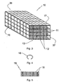
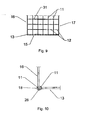
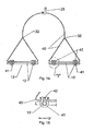
- a gabion (10) is formed by the joining of long (16-17) and short side meshes (36-37) respectively, forming the larger and smaller base sides of the gabion respectively, joined to a base (13), formed by one or more meshes (15) overlapping the base mesh (13), all joined (13-15) by staples (18) see Figure 9 , forming a prism-shaped gabion (10), which may adopt (as can be seen in Figures 1 and 3 ,) a prism-shaped configuration, although other geometrical figures are possible, being closed (10) by a cover (14).
- the long and (36-37) short side meshes (16-17), such as those that form part of the base (13), reinforced or not with a second reinforcement mesh (15) with the same or different size of grid (30), are built with horizontal and vertical rods (11-12) welded together forming grids (30) of (30) different sizes depending on type of material used for filling as well as of the type of force they exert on the meshes of the gabion, this filling for instance on the meshes (15-30), forming the base (13) of the gabion (10), use a smaller size of grid (30) to avoid the edged of the material projecting from the same (30), which on placing the gabion down (10) on the ground, or on another gabion (10) of the same or different size, could affect its settling and stability.
- joining two or more meshes (16), (13) and (37) for instance is done, as can be seen in Figure 10 , by staples (18), the configuration of which (as an example, but not exclusively in this manner) can be seen in in Figure 4 , which (18) come off a comb (19), through stapling gun (18), not shown in the illustrations.
- the staples (18) connect two or more rods (11), as may be seen in Figure 10 , but leaving a certain gap and/or play, so that joining two or more meshes (16), (13) and (37) for instance, leaves a gap (26), between the inner perimeter of the staple (18) and these rods (11) and (12), so that there is an elastic joint between meshes (16-13-37), giving the gabion spatial stability (10) after being loaded, vibrated and placed, or not the cover has the capacity to vary the distance between the different faces, and should be placed in its operating position.
- the transversal reinforcement meshes (31) may have the same or different configurations and grid size (30), firstly according to the weight of the filling load, the dimensions of the gabion (10) or the rod, or its placement regarding the separation between two or more meshes (31) can be the same or different.
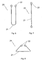
- bent rods (20-24) which act as a hook (20) formed by a metal U-shaped rod, the ends of which are bent to form closed loops (22), or the hook (24) formed by a U-shaped ben rod, whose arms are bent in convergence and whose free ends are bent on themselves forming loops (22).
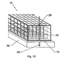
- a Bar grating has been fitted (27) perpendicular to the reinforcement base (13) of the gabion (10) and embedded in the foundations (39), and then a cylindrical tube (29) is placed around it, and finally concrete is poured between the cylindrical tube (29), and the bar grating (27), forming a compact post that facilitates the vertical rigidity of a wall when two or more gabions are placed (10) on top of each other, which if these posts did not exist, could become unstable, either by the weight of one or more of the gabions (10) on top of each other, or as a result of the thrust generated by the materials the sliding of which is what the containment wall is intended to prevent with two or more gabions (10).
- the gabions (35), in another different format to (10), as represented in Figure (12 ), with a thickness less than these gabions (10), can form a covering for a wall (33), as it has a "U"-shaped transversal section handrail (34), on which a support rests with an "L"-shaped transversal section (38), secured to one of the large bases of the gabion (35) by welding, bolts, clamps, or a similar technical resource.
- a cable is used (40), secured to one or more rods (12) of the base (13) of the gabion (10), by means of rings (41), the free ends of which are joined with bolts (42), clamping the rings (41) to the cable (40) and rods (12), so that the force of the weight of the filling material is spread regularly on most of the base area (13) being reinforced or not with another mesh (15) according to the weight of the filling material.
- This cable (40) has on its free ends triangles or loops, the lower base of which is what holds these rods (12) by means of the rings (41) and bolts (42), whereas the opposite ends of the cable (40) are joined to (40) again by terminals (32), a gabion being suspended (10), by means of a conventional hook or similar device (25) secured to the cable of a conventional crane, not shown in the illustrations.
- rods (20) and (23) can be used, in the configuration shown in in figures 6 and 8 , in which it can be seen how the rod (20) is bent into a "U" shape (21) and the ends form loops (22), while the rod (24) is bent into a triangular shape (21) whose ends are bent to form loops (22).
- longitudinal rods are used (23) with ends forming loops (22), to secure the long (16-17) or short (36-37) side meshes, as can be seen in Figure 7 .
Landscapes
- Engineering & Computer Science (AREA)
- Environmental & Geological Engineering (AREA)
- Life Sciences & Earth Sciences (AREA)
- General Life Sciences & Earth Sciences (AREA)
- Mining & Mineral Resources (AREA)
- Paleontology (AREA)
- Civil Engineering (AREA)
- General Engineering & Computer Science (AREA)
- Structural Engineering (AREA)
- Revetment (AREA)
Applications Claiming Priority (1)
| Application Number | Priority Date | Filing Date | Title |
|---|---|---|---|
| PCT/ES2009/070382 WO2011033142A1 (es) | 2009-09-15 | 2009-09-15 | Gavión para todo tipo de piedras naturales y residuos |
Publications (1)
| Publication Number | Publication Date |
|---|---|
| EP2479347A1 true EP2479347A1 (de) | 2012-07-25 |
Family
ID=43758139
Family Applications (1)
| Application Number | Title | Priority Date | Filing Date |
|---|---|---|---|
| EP09849400A Withdrawn EP2479347A1 (de) | 2009-09-15 | 2009-09-15 | Gabione für alle arten von naturgestein und abfall |
Country Status (2)
| Country | Link |
|---|---|
| EP (1) | EP2479347A1 (de) |
| WO (1) | WO2011033142A1 (de) |
Family Cites Families (11)
| Publication number | Priority date | Publication date | Assignee | Title |
|---|---|---|---|---|
| GB845863A (en) * | 1955-08-15 | 1960-08-24 | Penfold Fencing And Engineerin | Improvements in or relating to gabions |
| CH367113A (de) | 1958-09-26 | 1963-01-31 | Standard Telephon & Radio Ag | Rohrpost-Büchsenbremse |
| US4887691A (en) * | 1988-11-04 | 1989-12-19 | Rotondo/Penn-Cast | Modular wall construction using posts and panels |
| IT1264876B1 (it) * | 1993-06-22 | 1996-10-17 | Rdb Plastotecnica Spa | Procedimento per la realizzazione di una stuttura a celle per il contenimento di materiale incoerente per la stabilizzazione ed il |
| JP2633189B2 (ja) * | 1993-12-27 | 1997-07-23 | 株式会社ガソン | 布団篭 |
| US5860551A (en) | 1997-04-07 | 1999-01-19 | Knott, Sr.; James M. | Gabion container |
| JP2965556B1 (ja) * | 1998-08-27 | 1999-10-18 | 建設基礎エンジニアリング株式会社 | 蛇篭構造物 |
| DE20218181U1 (de) * | 2002-11-23 | 2003-03-27 | Rothfuss, Thomas, 71735 Eberdingen | Vorbau für Wände, wie Gebäudewände, Stützwände, Brüstungen, Stahlkonstruktionen und dgl. |
| JP2005171679A (ja) * | 2003-12-12 | 2005-06-30 | Takushin Koken:Kk | フトン篭工用成形具及びフトン篭工法 |
| GB0610054D0 (en) * | 2006-05-19 | 2006-06-28 | Hesco Bastion Ltd | Gabions |
| CH699050B1 (de) * | 2006-06-02 | 2010-01-15 | Fatzer Ag | Pressklaue zum Verbinden von Maschen von Drahtgeflechten oder Drahtnetzen, sowie eine Vorrichtung zum Verschliessen der Pressklauen. |
-
2009
- 2009-09-15 WO PCT/ES2009/070382 patent/WO2011033142A1/es not_active Ceased
- 2009-09-15 EP EP09849400A patent/EP2479347A1/de not_active Withdrawn
Non-Patent Citations (1)
| Title |
|---|
| See references of WO2011033142A1 * |
Also Published As
| Publication number | Publication date |
|---|---|
| WO2011033142A1 (es) | 2011-03-24 |
Similar Documents
| Publication | Publication Date | Title |
|---|---|---|
| AU2011268417B2 (en) | Mechanically stabilized earth welded wire wall facing system and method | |
| US20090304456A1 (en) | Two stage mechanically stabilized earth wall system | |
| JP2019127740A (ja) | 円柱金網籠とこれを用いた植生構造及び連結構造体 | |
| JP2020070607A (ja) | 土留め用籠構造物およびその形成方法 | |
| EP2479347A1 (de) | Gabione für alle arten von naturgestein und abfall | |
| US8632278B2 (en) | Mechanically stabilized earth welded wire facing connection system and method | |
| US8632281B2 (en) | Mechanically stabilized earth system and method | |
| US8632280B2 (en) | Mechanically stabilized earth welded wire facing connection system and method | |
| EP2581499B1 (de) | Gabione | |
| KR102352069B1 (ko) | 내진성능이 우수한 옹벽블록 보강지지 시스템 및 그 시공공법 | |
| KR101930001B1 (ko) | 개비온 펜스 및 개비온 펜스 시공방법 | |
| JP2004183276A (ja) | 土木工事用ふとんかご | |
| JP7075602B2 (ja) | 土木構造物及び土木構造物の構築方法 | |
| JP4129225B2 (ja) | 防護用堤体の構築方法 | |
| EP1848867B1 (de) | Verstärkungsstruktur | |
| KR102409371B1 (ko) | 상단 후크부를 가진 용접철망을 구비하는 리브형 pc 슬래브 및 리브형 pc 슬래브의 제작 및 시공 방법 | |
| SA515360770B1 (ar) | سياج وطريقة لتثبيت سياج | |
| EP3414401B1 (de) | Korb zur aufnahme von steinmaterialien zur verwendung bei der herstellung von trockenen steinwandstrukturen | |
| CN214303938U (zh) | 内外箍筋的柱型柔性模板 | |
| EP2674542B1 (de) | Armiertes Betonelement, wobei das Betonelement mit Stahlfasern verstärkt ist und einen Abstandhalter aufweist | |
| JP6957004B2 (ja) | 建築基礎用鉄筋ユニット | |
| KR101203730B1 (ko) | 모듈러 교각 구조물 및 교각 시공방법 | |
| KR20120131618A (ko) | 말뚝의 두부 보강 장치 | |
| US20230349124A1 (en) | Gabion type protection structure | |
| OA21173A (en) | Gabion type protection structure |
Legal Events
| Date | Code | Title | Description |
|---|---|---|---|
| PUAI | Public reference made under article 153(3) epc to a published international application that has entered the european phase |
Free format text: ORIGINAL CODE: 0009012 |
|
| 17P | Request for examination filed |
Effective date: 20120210 |
|
| AK | Designated contracting states |
Kind code of ref document: A1 Designated state(s): AT BE BG CH CY CZ DE DK EE ES FI FR GB GR HR HU IE IS IT LI LT LU LV MC MK MT NL NO PL PT RO SE SI SK SM TR |
|
| DAX | Request for extension of the european patent (deleted) | ||
| STAA | Information on the status of an ep patent application or granted ep patent |
Free format text: STATUS: THE APPLICATION IS DEEMED TO BE WITHDRAWN |
|
| 18D | Application deemed to be withdrawn |
Effective date: 20140401 |