EP2479136A2 - Locking device - Google Patents
Locking device Download PDFInfo
- Publication number
- EP2479136A2 EP2479136A2 EP11194296A EP11194296A EP2479136A2 EP 2479136 A2 EP2479136 A2 EP 2479136A2 EP 11194296 A EP11194296 A EP 11194296A EP 11194296 A EP11194296 A EP 11194296A EP 2479136 A2 EP2479136 A2 EP 2479136A2
- Authority
- EP
- European Patent Office
- Prior art keywords
- closing
- drive
- closing device
- gear member
- gear
- Prior art date
- Legal status (The legal status is an assumption and is not a legal conclusion. Google has not performed a legal analysis and makes no representation as to the accuracy of the status listed.)
- Withdrawn
Links
Images
Classifications
-
- B—PERFORMING OPERATIONS; TRANSPORTING
- B67—OPENING, CLOSING OR CLEANING BOTTLES, JARS OR SIMILAR CONTAINERS; LIQUID HANDLING
- B67B—APPLYING CLOSURE MEMBERS TO BOTTLES JARS, OR SIMILAR CONTAINERS; OPENING CLOSED CONTAINERS
- B67B3/00—Closing bottles, jars or similar containers by applying caps
- B67B3/20—Closing bottles, jars or similar containers by applying caps by applying and rotating preformed threaded caps
- B67B3/2013—Closing bottles, jars or similar containers by applying caps by applying and rotating preformed threaded caps by carousel-type capping machines
- B67B3/2033—Closing bottles, jars or similar containers by applying caps by applying and rotating preformed threaded caps by carousel-type capping machines comprising carousel co-rotating capping heads
-
- B—PERFORMING OPERATIONS; TRANSPORTING
- B67—OPENING, CLOSING OR CLEANING BOTTLES, JARS OR SIMILAR CONTAINERS; LIQUID HANDLING
- B67B—APPLYING CLOSURE MEMBERS TO BOTTLES JARS, OR SIMILAR CONTAINERS; OPENING CLOSED CONTAINERS
- B67B3/00—Closing bottles, jars or similar containers by applying caps
- B67B3/02—Closing bottles, jars or similar containers by applying caps by applying flanged caps, e.g. crown caps, and securing by deformation of flanges
- B67B3/10—Capping heads for securing caps
- B67B3/18—Capping heads for securing caps characterised by being rotatable, e.g. for forming screw threads in situ
Definitions
- the invention relates to a closure device for containers explained in the preamble of claim 1 Art.
- Such a closing device is for example from the EP-A-1 103 513 known.
- the known closing device is part of a filling system for beverage containers, in particular bottles, and contains a supporting center column, which is driven in rotation by a drive about a vertical axis.
- brackets for the container and each associated with each holder closing unit are arranged, which rotate with the center column about the vertical axis.
- a stationary frame is further provided, to which a lifting cam is mounted, on which the closing unit rolls with a roller arrangement such that a predetermined lifting movement of the closing unit can take place along the extended center line of the container, so that a closure from above the container can be placed.
- a rotary drive for the closing unit is further provided, with the aid of which, for example, screw caps can be screwed onto the container.
- the rotary drive includes a first gear member in the form of a gear which is rotatably mounted on the stationary frame.
- a second gear member in the form of a gear is located on the circumference of the closing unit and moves with this around the vertical axis of the column. Both gear members are engaged with each other, so that the gear members roll on each other and the closing unit is thereby rotated.
- the drive of the closing unit is thus derived from the drive of the transport device. However, this determines the direction of rotation and the speed of rotation. In addition, this type of drive requires extensive conversion measures when special user needs must be addressed.
- the invention is therefore based on the object to provide a closing device that provides a structurally simple way greater flexibility in the fulfillment of user wishes of the closing.
- the advantages of the transmission elements with respect to a simple construction and a functionally reliable, robust design are maintained, but increases the flexibility by a separate drive of the first of the transmission links.
- the drive can be used to adjust the speed to the particular screw cap used and the torque to the material of the screw cap and container, as well as rotational movements in both directions are easily possible.
- Torque motors are relatively compact, so that their runner may have a smaller outer diameter than the pitch circle of the holders of the container in the closing device and thus allows a compact design.
- the drive especially when using a hollow shaft motor, can easily sit on the rotating column, which acts as a drive for the transport device.
- the torque motor thus moves together with the column and independently, so that in a simple way changes in the transport speed can be included in the drive speed of the closing device.
- gear members As gear members, the proven gears can be used, friction wheels or the like. However, are also possible.
- one of the gear members is extended so that the engagement is maintained throughout the length of the linear motion.
- closure unit in a modular manner, wherein the various functions are combined into one assembly, so that for example Matching different rotary assemblies with the same lift assembly or different lift assemblies with the same rotary assembly and can be replaced depending on the type of container to be handled by the user.
- the closing unit can also have a replaceable closing head, which is adapted to different closure constructions.
- the closing units can be kept ready for any type of container or closure and, if appropriate, also provided for retrofitting already in operation closing devices.
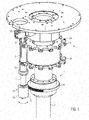
- Fig. 1 shows a perspective, schematic partial representation of a closing device 1 of substantially conventional design.
- the closing device 1 comprises a vertical center column 2, which comprises an inner, non-stationary but height-resistant support 3 and an outer, about its vertical center line 4 'driven rotary sleeve 4.
- the holders for the container and a holder 5 for at least one closing unit 6 are mounted in a conventional and not shown manner.
- the holder 5 contains in the illustrated embodiment, two superimposed pitch circles 5a and 5b hold the closing units 6 in circumferential distance from each other.
- a stationary head plate 7 On which a lifting cam 9 is arranged on a downwardly projecting flange 8, in which in a known manner a roller 10 engages, which is rotatably mounted on the closing unit 6.
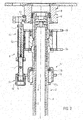
- a lifting cylinder 11 With the roller 10, a lifting cylinder 11 is connected, in a guide sleeve 12 in the vertical direction, ie in the direction of the aligned center lines 11 'of the lifting cylinder 11 and the center line 13' a container 13 ( Fig. 3 ) is arranged displaceably.
- the guide sleeve 12 is connected to the holder 5.
- Roller 10 and lifting cylinder 11 form a hub assembly 14th
- the stroke can also be carried out by electric motor or pneumatically
- a rotary assembly 15 is rotatably mounted about the central axis 11 'of the lifting cylinder 11. The attachment is made such that the two assemblies 14 and 15 are interchangeable attached to each other.
- the rotary assembly 15 includes a sleeve-shaped carrier 16, which on the lifting cylinder 11 facing away from the lower end either a fixed locking head or a clutch which is able to interchangeably absorb different Verschetzkopftypen.
- the drive via a hollow shaft motor, in particular a so-called torque motor in the hollow shaft design, which sits without connection with the lifting cam 9, with its hollow stator 17a on the rotary sleeve 4 of the central column 2 and rotates with this about the center line 4 ', and an external rotor 17b, which is provided on its outside with a first gear member 18 in the form of a gear, a pinion or a ring gear, which extends coaxially about the center line 4 'of the rotary sleeve 4.
- Engine and storage form a single unit.
- This first gear member 18 of the drive 17 drives the rotary assembly 15 in the desired direction of rotation separately and independently of the drive of the rotary sleeve 4 of the central column 2 via a second gear member 19.
- the second gear member 19 is also a gear, but has an axial length in the direction of the center line 11 ', which is greater than the axial length of the first gear member 18 and at least as large as that caused by the lifting cam 4 stroke of the lifting cylinder 11, so that in each stage of the lifting movement of the drive 17 acts on the rotary assembly 15.
- the second gear member 19 is fixed in the illustrated embodiment on the outside of the sleeve 16
- the control of the drive 17 and its power supply via cables which preferably extend in the interior of the central column 2, and for example a slip ring transmitter, or contactless.
- the closing device according to the invention can be adapted in a structurally simple manner to certain user requirements, be it already during manufacture, be it for retrofitting.
- the Wegemesssystem can detect the speed of the capping head and optionally regulate what z.
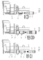
- Fig. 3 to 5 show various possibilities of application of the closing device according to the invention.
- Fig. 3 shows the use of the closure device according to the invention for applying screw caps.
- the container 13 is aligned with its center line 13 'in alignment with the center line 11' of the lifting cylinder and a capping head 20 for applying screw caps or a Greiferverschmonykopf or the like.
- the central column 2 is driven and the drive 17 set in motion to actuate the assemblies of the closing unit 6 by a combined linear movement in the height direction (stroke) and rotational movement about the vertical axis 11 'for screwing the screw cap on the container 13.
- Fig. 4 shows a closing device according to the invention for applying Aluanrollver whiln on container 13. Like Fig. 4 shows, the closing device corresponds to Fig. 4 the closing device according to Fig. 3 with regard to the hub assembly 14 and the rotary assembly 15. What has been changed is only the capping head, which has been replaced by an aluminum rolling head 21 capable of applying these aluminum roller shutters.
- Fig. 5 shows a closing device according to the invention equipped for applying crown corks.
- the closure unit here includes the lift assembly 14 while the rotary assembly has been removed and a crown cork capping head 22 or aluminum sealing head or the like has been directly attached to the lift assembly 14.
- the drive 17 is thus shut down, can however, remain in place if further conversion to screw caps is expected.
- the closing unit can also be designed with a head drive, preferably when the modular or assembly structure is not necessary.
- This is also the rotary or screw drive above the holder for the container.
- the torque motor can be easily encapsulated, d. H. be housed in a protective housing that leaves only the sprocket so that the cleaning is greatly facilitated.
- other motors can preferably be used with a hollow shaft.
- the two gear members do not necessarily directly engage with each other, intermediate links may also be provided.
- the described drive can also be provided without a separate drive in Verschnoviseren without module division, and the module blocks.
Abstract
Description
Die Erfindung bezieht sich auf eine Verschließeinrichtung für Behälter der im Oberbegriff von Anspruch 1 erläuterten Art.The invention relates to a closure device for containers explained in the preamble of claim 1 Art.
Eine derartige Verschließeinrichtung ist beispielsweise aus der
Es ist weiterhin aus der
Der Erfindung liegt somit die Aufgabe zugrunde, eine Verschließeinrichtung bereit zu stellen, die auf konstruktiv einfache Weise eine größere Flexibilität bei der Erfüllung von Benutzerwünschen der Verschließeinrichtung bietet.The invention is therefore based on the object to provide a closing device that provides a structurally simple way greater flexibility in the fulfillment of user wishes of the closing.
Die Aufgabe wird durch die im Anspruch 1 angegebenen Merkmale gelöst.The object is solved by the features specified in claim 1.
Durch die erfindungsgemäße Ausgestaltung werden die Vorteile der Getriebeglieder in Hinblick auf eine einfache Konstruktion und eine funktionssichere, robuste Ausgestaltung beibehalten, die Flexibilität jedoch durch einen eigenen Antrieb des ersten der Getriebeglieder erhöht. Durch den Antrieb kann die Geschwindigkeit an den speziell verwendeten Schraubverschluss und das Drehmoment auf das Material von Schraubverschluss und Behälter angepasst werden, außerdem sind ohne weiteres Drehbewegungen in beiden Richtungen möglich.Due to the inventive design, the advantages of the transmission elements with respect to a simple construction and a functionally reliable, robust design are maintained, but increases the flexibility by a separate drive of the first of the transmission links. The drive can be used to adjust the speed to the particular screw cap used and the torque to the material of the screw cap and container, as well as rotational movements in both directions are easily possible.
Vorteilhafte Weiterbildungen der Erfindung sind den Unteransprüchen zu entnehmen.Advantageous developments of the invention can be found in the dependent claims.
Als Antrieb besonders geeignet ist ein Torque-Motor wegen seiner einfachen und robusten Ausgestaltung und der guten Steuerungsmöglichkeit, der bevorzugt in Hohlwellenausführung und mit Außenläufer eingesetzt wird. Torque-Motoren sind relativ kompakt, so dass ihr Läufer einen geringeren Außendurchmesser aufweisen kann, als der Teilkreis der Halterungen der Behälter in der Verschließeinrichtung und somit eine kompakte Ausbildung gestattet.Particularly suitable as a drive is a torque motor because of its simple and robust design and the good control option, which is preferably used in hollow shaft design and with external rotor. Torque motors are relatively compact, so that their runner may have a smaller outer diameter than the pitch circle of the holders of the container in the closing device and thus allows a compact design.
Der Antrieb, insbesondere bei Verwendung eines Hohlwellen-Motors, kann problemlos auf der rotierenden Säule sitzen, die als Antrieb für die Transporteinrichtung wirkt. Der Torque-Motor bewegt sich somit zusammen mit der Säule und unabhängig davon, so dass auf einfache Weise Änderungen der Transportgeschwindigkeit in die Antriebsgeschwindigkeit der Verschließeinrichtung einbezogen werden können.The drive, especially when using a hollow shaft motor, can easily sit on the rotating column, which acts as a drive for the transport device. The torque motor thus moves together with the column and independently, so that in a simple way changes in the transport speed can be included in the drive speed of the closing device.
Als Getriebeglieder können die bewährten Zahnräder eingesetzt werden, Reibräder oder dgl. sind jedoch ebenfalls möglich.As gear members, the proven gears can be used, friction wheels or the like. However, are also possible.
Durch die Beibehaltung der Getriebeglieder ist es auch möglich, trotz separatem Antrieb, alle Verschließeinheiten einer Verschließeinrichtung mit einem einzigen separaten Antrieb anzutreiben.By maintaining the gear members, it is also possible, despite a separate drive, to drive all closing units of a closing device with a single separate drive.
Zum Ausgleich der Linearbewegungen entlang der Behältermittellinie ist eines der Getriebeglieder verlängert, so dass der Eingriff über die gesamte Länge der Linearbewegung aufrecht erhalten bleibt.To compensate for the linear movements along the container centerline, one of the gear members is extended so that the engagement is maintained throughout the length of the linear motion.
Eine weitere Möglichkeit, die Flexibilität beim Berücksichtigen von Benutzerwünschen zu erhöhen, die gemeinsam oder unabhängig vom separaten, unabhängigen Antrieb vorgesehen sein kann, ist die Ausgestaltung der Verschließeinheit in modularer Art und Weise, wobei die verschiedenen Funktionen in jeweils eine Baugruppe zusammengefasst sind, so dass beispielsweise verschiedene Dreh-Baugruppen mit der gleichen Hub-Baugruppe oder verschiedene Hub-Baugruppen mit der gleichen Dreh-Baugruppe zusammenpassen und je nach der beim Benutzer zu handhabenden Art der Behälter ausgetauscht werden können.Another way to increase the flexibility in accommodating user wishes, which may be provided together or independently of the separate, independent drive, is the design of the closure unit in a modular manner, wherein the various functions are combined into one assembly, so that for example Matching different rotary assemblies with the same lift assembly or different lift assemblies with the same rotary assembly and can be replaced depending on the type of container to be handled by the user.
Zusätzlich oder alternativ kann die Verschließeinheit auch einen auswechselbaren Verschließkopf aufweisen, der an unterschiedliche Verschlusskonstruktionen angepasst ist.Additionally or alternatively, the closing unit can also have a replaceable closing head, which is adapted to different closure constructions.
Die Verschließeinheiten können für jede Art eines Behälters beziehungsweise eines Verschlusses bereit gehalten und, gegebenenfalls auch zum Nachrüsten bereits in Betrieb befindlicher Verschließeinrichtungen bereit gestellt werden.The closing units can be kept ready for any type of container or closure and, if appropriate, also provided for retrofitting already in operation closing devices.
Ein Ausführungsbeispiel der Erfindung wird nachfolgend anhand der Zeichnungen näher erläutert. Es zeigen:
- Fig. 1
- eine perspektivische Teildarstellung einer erfindungsgemäßen Verschließeinrichtung,
- Fig. 2
- einen Axialschnitt der Verschließeinrichtung nach
Fig. 1 , - Fig. 3 bis 5
- verschiedene Ausführungsformen von Verschließeinheiten.
- Fig. 1
- a partial perspective view of a closing device according to the invention,
- Fig. 2
- an axial section of the closing device according to
Fig. 1 . - Fig. 3 to 5
- various embodiments of sealing units.
Oberhalb der zentralen Säule 2 ist eine ortsfeste Kopfplatte 7 vorgesehen, an der an einem nach unten vorstehenden Flansch 8 eine Hubkurve 9 angeordnet ist, in die in bekannter Weise eine Laufrolle 10 eingreift, die an der Verschließeinheit 6 drehbar gelagert ist. Mit der Laufrolle 10 ist ein Hubzylinder 11 verbunden, der in einer Führungshülse 12 in senkrechter Richtung, d.h. in Richtung der ausgerichteten Mittellinien 11' des Hubzylinders 11 und der Mittellinie 13' eines Behälter 13 (
Statt durch die Hubkurve 9, kann der Hub auch elektromotorisch oder pneumatisch erfolgenInstead of the
An der der Laufrolle 10 abgewandten, unteren Ebene des Hubzylinders 11 ist eine Dreh-Baugruppe 15 um die Mittelachse 11' des Hubzylinders 11 drehbar befestigt. Die Befestigung erfolgt derart, dass die beiden Baugruppen 14 und 15 austauschbar aneinander befestigt sind.At the
Die Dreh-Baugruppe 15 enthält einen hülsenförmigen Träger 16, der an dem dem Hubzylinder 11 abgewandten, unteren Ende entweder einen fest angeordneten Verschließkopf oder eine Kupplung aufweist, die in der Lage ist, verschiedene Verschließkopftypen auswechselbar aufzunehmen.The
Der Antrieb der Dreh-Baugruppen 15 aller Verschließeinheiten 6 erfolgt über einen separaten Antrieb 17, der unabhängig ist vom (nicht gezeigten) Antrieb der Zentralsäule. Bevorzugt erfolgt der Antrieb über einen Hohlwellenmotor, insbesondere einen sogenannten Torque-Motor in Hohlwellenausführung, der ohne Verbindung mit der Hubkurve 9, mit seinem hohlen Stator 17a auf der Drehhülse 4 der Zentralsäule 2 sitzt und sich mit dieser um die Mittellinie 4' dreht, und einen Außenläufer 17b, der an seiner Außenseite mit einem ersten Getriebeglied 18 in Form eines Zahnrades, eines Ritzels oder eines Zahnkranzes versehen ist, das sich koaxial um die Mittellinie 4' der Drehhülse 4 erstreckt. Motor und Lagerung bilden dabei eine Einheit.The drive of the
Dieses erste Getriebeglied 18 des Antriebs 17 treibt über ein zweites Getriebeglied 19 die Dreh-Baugruppe 15 in der gewünschten Drehrichtung separat und unabhängig vom Antrieb der Drehhülse 4 der Zentralsäule 2 an. Das zweite Getriebeglied 19 ist ebenfalls ein Zahnrad, weist jedoch eine axiale Länge in Richtung der Mittellinie 11' auf, die größer ist als die axiale Länge des ersten Getriebegliedes 18 und mindestens so groß ist wie der durch die Hubkurve 4 bewirkte Hubweg des Hubzylinders 11, so dass in jedem Stadium der Hubbewegung der Antrieb 17 auf die Dreh-Baugruppe 15 einwirkt. Das zweite Getriebeglied 19 ist im dargestellten Ausführungsbeispiel an der Außenseite der Hülse 16 befestigtThis
Die Steuerung des Antriebs 17 und seine Stromversorgung erfolgt über Kabel, die bevorzugt im inneren der Zentralsäule 2 verlaufen, und z.B. einen Schleifringüberträger, oder berührungslos.The control of the
Mit der erfindungsgemäßen Ausgestaltung kann somit das Aufschrauben von Schraubverschlüssen jeder Art in beiden Richtungen und exakt gesteuert mit einem vorgegebenen Drehmoment erfolgen, so dass die Behälter gut verschlossen werden, ohne dass die Gefahr von Beschädigungen besteht.With the embodiment according to the invention can thus be done screwing screw caps of any kind in both directions and precisely controlled with a predetermined torque, so that the container are well closed, without the risk of damage.
Durch die modulare Ausgestaltung kann die erfindungsgemäße Verschließeinrichtung auf konstruktiv einfache Weise an bestimmte Benutzeranforderungen, sei es bereits bei der Herstellung, sei es für eine Nachrüstung, angepasst werden.Due to the modular design, the closing device according to the invention can be adapted in a structurally simple manner to certain user requirements, be it already during manufacture, be it for retrofitting.
Es kann weiterhin ein Wegemesssystem vorgesehen sein, das den Grad des Aufschraubens der Verschlüsse auf den Behältern nachverfolgt und den Antrieb 17 entsprechend steuert. Das Wegemesssystem kann die Drehzahl des Verschließkopfes erfassen und gegebenenfalls regeln, wozu z. B. ein Drehwertgeber zwischen Läufer und Stator angeordnet ist. Es ist aber auch möglich, im Bereich des Getriebeglieds 19 die Drehzahl des Verschließkopfes zu erfassen.It can also be provided a Wegemesssystem that tracks the degree of screwing the closures on the containers and controls the
Die
In Abwandlung des beschriebenen und gezeichneten Ausführungsbeispiels kann die Verschließeinheit auch mit Kopfantrieb ausgebildet sein, bevorzugt dann, wenn der modulare beziehungsweise Baugruppen-Aufbau nicht notwendig ist. Dabei befindet sich auch der Dreh- bzw. Schraubantrieb oberhalb der Halterung für die Behälter. Der Torque-Motor kann auf einfache Weise gekapselt, d. h. in einem Schutzgehäuse untergebracht werden, das nur den Zahnkranz freilässt, so dass die Reinigung stark erleichtert wird. Statt des Torque-Motors können andere Motoren bevorzugt mit Hohlwelle eingesetzt werden. Schließlich müssen die beiden Getriebeglieder nicht unbedingt direkt miteinander in Eingriff stehen, Zwischenglieder können ebenfalls vorgesehen sein. Der beschriebene Antrieb kann auch bei Verschließeinheiten ohne Baugruppenunterteilung, und die Baugruppenbausteine auch ohne separaten Antrieb vorgesehen werden.In a modification of the described and illustrated embodiment, the closing unit can also be designed with a head drive, preferably when the modular or assembly structure is not necessary. This is also the rotary or screw drive above the holder for the container. The torque motor can be easily encapsulated, d. H. be housed in a protective housing that leaves only the sprocket so that the cleaning is greatly facilitated. Instead of the torque motor, other motors can preferably be used with a hollow shaft. Finally, the two gear members do not necessarily directly engage with each other, intermediate links may also be provided. The described drive can also be provided without a separate drive in Verschließeinheiten without module division, and the module blocks.
Claims (13)
Applications Claiming Priority (1)
| Application Number | Priority Date | Filing Date | Title |
|---|---|---|---|
| DE102011003118A DE102011003118A1 (en) | 2011-01-25 | 2011-01-25 | closing |
Publications (2)
| Publication Number | Publication Date |
|---|---|
| EP2479136A2 true EP2479136A2 (en) | 2012-07-25 |
| EP2479136A3 EP2479136A3 (en) | 2012-10-17 |
Family
ID=45444427
Family Applications (1)
| Application Number | Title | Priority Date | Filing Date |
|---|---|---|---|
| EP11194296A Withdrawn EP2479136A3 (en) | 2011-01-25 | 2011-12-19 | Locking device |
Country Status (4)
| Country | Link |
|---|---|
| US (1) | US20120186194A1 (en) |
| EP (1) | EP2479136A3 (en) |
| CN (1) | CN102616708B (en) |
| DE (1) | DE102011003118A1 (en) |
Cited By (2)
| Publication number | Priority date | Publication date | Assignee | Title |
|---|---|---|---|---|
| WO2024057196A1 (en) * | 2022-09-12 | 2024-03-21 | Arol S.P.A. | Closing assembly for capping head for capping machine and capping machine |
| WO2024057197A1 (en) * | 2022-09-12 | 2024-03-21 | Arol S.P.A. | Closing assembly for capping head of a capping machine |
Families Citing this family (40)
| Publication number | Priority date | Publication date | Assignee | Title |
|---|---|---|---|---|
| US8414505B1 (en) | 2001-02-15 | 2013-04-09 | Hansen Medical, Inc. | Catheter driver system |
| DE102009045637A1 (en) * | 2009-10-13 | 2011-04-14 | Krones Ag | Method and device for screw-closing vessels, in particular bottles |
| US20130317519A1 (en) | 2012-05-25 | 2013-11-28 | Hansen Medical, Inc. | Low friction instrument driver interface for robotic systems |
| US9668814B2 (en) | 2013-03-07 | 2017-06-06 | Hansen Medical, Inc. | Infinitely rotatable tool with finite rotating drive shafts |
| US20140277334A1 (en) | 2013-03-14 | 2014-09-18 | Hansen Medical, Inc. | Active drives for robotic catheter manipulators |
| US11213363B2 (en) | 2013-03-14 | 2022-01-04 | Auris Health, Inc. | Catheter tension sensing |
| US9326822B2 (en) | 2013-03-14 | 2016-05-03 | Hansen Medical, Inc. | Active drives for robotic catheter manipulators |
| US9498601B2 (en) | 2013-03-14 | 2016-11-22 | Hansen Medical, Inc. | Catheter tension sensing |
| US9173713B2 (en) | 2013-03-14 | 2015-11-03 | Hansen Medical, Inc. | Torque-based catheter articulation |
| US9408669B2 (en) | 2013-03-15 | 2016-08-09 | Hansen Medical, Inc. | Active drive mechanism with finite range of motion |
| US20140276936A1 (en) | 2013-03-15 | 2014-09-18 | Hansen Medical, Inc. | Active drive mechanism for simultaneous rotation and translation |
| US9452018B2 (en) | 2013-03-15 | 2016-09-27 | Hansen Medical, Inc. | Rotational support for an elongate member |
| US20140276647A1 (en) | 2013-03-15 | 2014-09-18 | Hansen Medical, Inc. | Vascular remote catheter manipulator |
| US9763741B2 (en) | 2013-10-24 | 2017-09-19 | Auris Surgical Robotics, Inc. | System for robotic-assisted endolumenal surgery and related methods |
| US9713509B2 (en) | 2013-10-24 | 2017-07-25 | Auris Surgical Robotics, Inc. | Instrument device manipulator with back-mounted tool attachment mechanism |
| US10046140B2 (en) | 2014-04-21 | 2018-08-14 | Hansen Medical, Inc. | Devices, systems, and methods for controlling active drive systems |
| US10569052B2 (en) | 2014-05-15 | 2020-02-25 | Auris Health, Inc. | Anti-buckling mechanisms for catheters |
| US9561083B2 (en) | 2014-07-01 | 2017-02-07 | Auris Surgical Robotics, Inc. | Articulating flexible endoscopic tool with roll capabilities |
| EP3346899B1 (en) * | 2015-09-09 | 2022-11-09 | Auris Health, Inc. | Instrument device manipulator for a surgical robotics system |
| US9949749B2 (en) | 2015-10-30 | 2018-04-24 | Auris Surgical Robotics, Inc. | Object capture with a basket |
| US9955986B2 (en) | 2015-10-30 | 2018-05-01 | Auris Surgical Robotics, Inc. | Basket apparatus |
| US10639108B2 (en) | 2015-10-30 | 2020-05-05 | Auris Health, Inc. | Process for percutaneous operations |
| US10454347B2 (en) | 2016-04-29 | 2019-10-22 | Auris Health, Inc. | Compact height torque sensing articulation axis assembly |
| US11241559B2 (en) | 2016-08-29 | 2022-02-08 | Auris Health, Inc. | Active drive for guidewire manipulation |
| KR20230096148A (en) | 2016-08-31 | 2023-06-29 | 아우리스 헬스, 인코포레이티드 | Length conservative surgical instrument |
| US10244926B2 (en) | 2016-12-28 | 2019-04-02 | Auris Health, Inc. | Detecting endolumenal buckling of flexible instruments |
| US10543048B2 (en) | 2016-12-28 | 2020-01-28 | Auris Health, Inc. | Flexible instrument insertion using an adaptive insertion force threshold |
| DE102017112218B3 (en) * | 2017-06-02 | 2018-08-09 | Khs Gmbh | Capping machine of circumferential design |
| US11026758B2 (en) | 2017-06-28 | 2021-06-08 | Auris Health, Inc. | Medical robotics systems implementing axis constraints during actuation of one or more motorized joints |
| EP3723655A4 (en) | 2017-12-11 | 2021-09-08 | Auris Health, Inc. | Systems and methods for instrument based insertion architectures |
| KR20200100613A (en) | 2017-12-14 | 2020-08-26 | 아우리스 헬스, 인코포레이티드 | System and method for estimating instrument position |
| US10888386B2 (en) | 2018-01-17 | 2021-01-12 | Auris Health, Inc. | Surgical robotics systems with improved robotic arms |
| EP3813632A4 (en) | 2018-06-27 | 2022-03-09 | Auris Health, Inc. | Alignment and attachment systems for medical instruments |
| CN112752534A (en) | 2018-09-28 | 2021-05-04 | 奥瑞斯健康公司 | Apparatus, system and method for manual and robotic driving of medical instruments |
| WO2020197671A1 (en) | 2019-03-22 | 2020-10-01 | Auris Health, Inc. | Systems and methods for aligning inputs on medical instruments |
| DE102019112250A1 (en) * | 2019-05-10 | 2020-11-12 | Khs Gmbh | Closing device for closing containers |
| US11896330B2 (en) | 2019-08-15 | 2024-02-13 | Auris Health, Inc. | Robotic medical system having multiple medical instruments |
| WO2021064536A1 (en) | 2019-09-30 | 2021-04-08 | Auris Health, Inc. | Medical instrument with capstan |
| WO2021137071A1 (en) | 2019-12-31 | 2021-07-08 | Auris Health, Inc. | Advanced basket drive mode |
| WO2021137104A1 (en) | 2019-12-31 | 2021-07-08 | Auris Health, Inc. | Dynamic pulley system |
Citations (2)
| Publication number | Priority date | Publication date | Assignee | Title |
|---|---|---|---|---|
| EP1103513A1 (en) | 1999-11-23 | 2001-05-30 | Sergio Cirio | Device and method for checking the closure of a threaded capsule on a container |
| WO2008145363A1 (en) | 2007-05-31 | 2008-12-04 | Khs Ag | Machine having a direct drive for the treatment of containers |
Family Cites Families (18)
| Publication number | Priority date | Publication date | Assignee | Title |
|---|---|---|---|---|
| US2987313A (en) * | 1957-05-28 | 1961-06-06 | Owens Illinois Glass Co | Bottle holder |
| US3660963A (en) * | 1970-05-28 | 1972-05-09 | Crown Cork & Seal Co | Container closing apparatus and method |
| US5419094A (en) * | 1994-03-02 | 1995-05-30 | Crown Cork & Seal Company, Inc. | Constant speed spindles for rotary capping machine |
| DE4415227A1 (en) * | 1994-04-30 | 1995-11-02 | Mewes Gmbh | Flask cap screwing=on process |
| DE4419323A1 (en) * | 1994-06-02 | 1995-12-07 | Mewes Gmbh | Screw cap fitting machine |
| US5996311A (en) * | 1998-08-10 | 1999-12-07 | Krones, Inc. | Device for tightening caps on containers |
| IT1304700B1 (en) * | 1998-12-23 | 2001-03-28 | Antas S P A | EQUIPMENT FOR GLASS WORKING WITH A PERFORATED ROUNDING SYSTEM AND ITS CONTROL METHOD |
| CN2443532Y (en) * | 2000-07-20 | 2001-08-15 | 张习斌 | Efficient high-specific energy laminated permanent-magnet non-iron core brushless electric machine |
| DE202004021791U1 (en) * | 2004-05-29 | 2011-02-10 | Krones Ag | Machine for aligning and equipping objects |
| DE102007028429A1 (en) * | 2007-06-20 | 2008-12-24 | Krones Ag | Device for closing containers with screw caps |
| CN101157433B (en) * | 2007-11-20 | 2012-01-25 | 金坛市中正包装机械科技有限公司 | Lifting gear of cap whirling machine |
| FR2924705B1 (en) * | 2007-12-05 | 2012-02-03 | Serac Group | DEVICE FOR CLOSING CONTAINERS WITH CONTROLLED POLLUTION |
| CN201208701Y (en) * | 2008-05-20 | 2009-03-18 | 南京数控机床有限公司 | Turntable clamper control valve |
| ITTO20080712A1 (en) * | 2008-09-30 | 2010-04-01 | Arol Spa | MACHINE FOR THE APPLICATION OF THREADED CONTAINER CAPSULES |
| CN101386399A (en) * | 2008-10-09 | 2009-03-18 | 上海交通大学 | Servo bottle cap screwing mechanism |
| DE102008056242A1 (en) * | 2008-11-06 | 2010-05-12 | Krones Ag | Closure device for containers with sterile space |
| DE102008057900A1 (en) * | 2008-11-18 | 2010-05-20 | Krones Ag | Electric motor for bottle capper |
| DE102009017109A1 (en) * | 2009-04-15 | 2010-10-28 | Khs Gmbh | Capper for screw caps or caps |
-
2011
- 2011-01-25 DE DE102011003118A patent/DE102011003118A1/en not_active Withdrawn
- 2011-12-19 EP EP11194296A patent/EP2479136A3/en not_active Withdrawn
-
2012
- 2012-01-23 US US13/355,669 patent/US20120186194A1/en not_active Abandoned
- 2012-01-30 CN CN201210028391.9A patent/CN102616708B/en not_active Expired - Fee Related
Patent Citations (2)
| Publication number | Priority date | Publication date | Assignee | Title |
|---|---|---|---|---|
| EP1103513A1 (en) | 1999-11-23 | 2001-05-30 | Sergio Cirio | Device and method for checking the closure of a threaded capsule on a container |
| WO2008145363A1 (en) | 2007-05-31 | 2008-12-04 | Khs Ag | Machine having a direct drive for the treatment of containers |
Cited By (2)
| Publication number | Priority date | Publication date | Assignee | Title |
|---|---|---|---|---|
| WO2024057196A1 (en) * | 2022-09-12 | 2024-03-21 | Arol S.P.A. | Closing assembly for capping head for capping machine and capping machine |
| WO2024057197A1 (en) * | 2022-09-12 | 2024-03-21 | Arol S.P.A. | Closing assembly for capping head of a capping machine |
Also Published As
| Publication number | Publication date |
|---|---|
| CN102616708A (en) | 2012-08-01 |
| US20120186194A1 (en) | 2012-07-26 |
| DE102011003118A1 (en) | 2012-07-26 |
| EP2479136A3 (en) | 2012-10-17 |
| CN102616708B (en) | 2015-04-01 |
Similar Documents
| Publication | Publication Date | Title |
|---|---|---|
| EP2479136A2 (en) | Locking device | |
| EP2217523B1 (en) | Device for closing containers | |
| EP2155563B1 (en) | Machine having a direct drive for the treatment of containers | |
| EP2255923B1 (en) | Rotary table | |
| EP3630670B1 (en) | Rotary-type capping machine | |
| DE19542453A1 (en) | Device for converting a rotary movement into an axial movement | |
| EP2958848B1 (en) | Unit and machine for closing of containers | |
| EP2105404A2 (en) | Table for container handling machines and container handling machine | |
| EP1834923A1 (en) | Screw capper for bottles or similar | |
| EP3504102B1 (en) | Steering wheel for controlling steering movement of a vehicle | |
| DE19807432A1 (en) | Drive for an electrically operated vehicle brake | |
| EP2714528B1 (en) | Handling machine for containers | |
| DE102008060043B3 (en) | screw press | |
| EP2576418B1 (en) | Device for processing a product, having an element for processing the product | |
| DE102008037101A1 (en) | Height adjustment apparatus for use in rotor of container handling device i.e. container filling machine, has height adjusting device connected with rotor drive over coupling for changing distance between valve support and retainer | |
| EP3728102B1 (en) | Spindle shaft unit for a device for the rotary closing of containers with a screw closure | |
| DE2240933A1 (en) | DETACHABLE HEAD SET FOR THE SEALING HEAD OF A SEALING MACHINE | |
| DE3443756A1 (en) | Device for lifting and controlled unwinding and winding of a drum | |
| DE1588622C3 (en) | Generator without slip rings for controlling auxiliary equipment of a rail vehicle | |
| EP0889002A1 (en) | Device for screwing threaded caps on beverage bottles | |
| EP0498318A2 (en) | Device for adjusting a filling height | |
| DE69826169T2 (en) | Drive mechanism for a Ausnehmerarm | |
| EP2736835B1 (en) | Device for closing containers | |
| DE3228476C2 (en) | ||
| DE102004055611B4 (en) | Device, in particular for driving a lifting movement and a pivoting movement exporting institution |
Legal Events
| Date | Code | Title | Description |
|---|---|---|---|
| PUAI | Public reference made under article 153(3) epc to a published international application that has entered the european phase |
Free format text: ORIGINAL CODE: 0009012 |
|
| AK | Designated contracting states |
Kind code of ref document: A2 Designated state(s): AL AT BE BG CH CY CZ DE DK EE ES FI FR GB GR HR HU IE IS IT LI LT LU LV MC MK MT NL NO PL PT RO RS SE SI SK SM TR |
|
| AX | Request for extension of the european patent |
Extension state: BA ME |
|
| PUAL | Search report despatched |
Free format text: ORIGINAL CODE: 0009013 |
|
| AK | Designated contracting states |
Kind code of ref document: A3 Designated state(s): AL AT BE BG CH CY CZ DE DK EE ES FI FR GB GR HR HU IE IS IT LI LT LU LV MC MK MT NL NO PL PT RO RS SE SI SK SM TR |
|
| AX | Request for extension of the european patent |
Extension state: BA ME |
|
| RIC1 | Information provided on ipc code assigned before grant |
Ipc: B67B 3/18 20060101AFI20120912BHEP Ipc: B67B 3/20 20060101ALI20120912BHEP |
|
| 17P | Request for examination filed |
Effective date: 20130416 |
|
| 17Q | First examination report despatched |
Effective date: 20160331 |
|
| STAA | Information on the status of an ep patent application or granted ep patent |
Free format text: STATUS: THE APPLICATION IS DEEMED TO BE WITHDRAWN |
|
| 18D | Application deemed to be withdrawn |
Effective date: 20160811 |