EP2155563B1 - Machine having a direct drive for the treatment of containers - Google Patents
Machine having a direct drive for the treatment of containers Download PDFInfo
- Publication number
- EP2155563B1 EP2155563B1 EP08758850.5A EP08758850A EP2155563B1 EP 2155563 B1 EP2155563 B1 EP 2155563B1 EP 08758850 A EP08758850 A EP 08758850A EP 2155563 B1 EP2155563 B1 EP 2155563B1
- Authority
- EP
- European Patent Office
- Prior art keywords
- motor
- drive
- housing
- unit
- rotor
- Prior art date
- Legal status (The legal status is an assumption and is not a legal conclusion. Google has not performed a legal analysis and makes no representation as to the accuracy of the status listed.)
- Not-in-force
Links
Images

Classifications
-
- B—PERFORMING OPERATIONS; TRANSPORTING
- B67—OPENING, CLOSING OR CLEANING BOTTLES, JARS OR SIMILAR CONTAINERS; LIQUID HANDLING
- B67C—CLEANING, FILLING WITH LIQUIDS OR SEMILIQUIDS, OR EMPTYING, OF BOTTLES, JARS, CANS, CASKS, BARRELS, OR SIMILAR CONTAINERS, NOT OTHERWISE PROVIDED FOR; FUNNELS
- B67C3/00—Bottling liquids or semiliquids; Filling jars or cans with liquids or semiliquids using bottling or like apparatus; Filling casks or barrels with liquids or semiliquids
- B67C3/02—Bottling liquids or semiliquids; Filling jars or cans with liquids or semiliquids using bottling or like apparatus
- B67C3/22—Details
-
- B—PERFORMING OPERATIONS; TRANSPORTING
- B65—CONVEYING; PACKING; STORING; HANDLING THIN OR FILAMENTARY MATERIAL
- B65C—LABELLING OR TAGGING MACHINES, APPARATUS, OR PROCESSES
- B65C9/00—Details of labelling machines or apparatus
-
- B—PERFORMING OPERATIONS; TRANSPORTING
- B67—OPENING, CLOSING OR CLEANING BOTTLES, JARS OR SIMILAR CONTAINERS; LIQUID HANDLING
- B67B—APPLYING CLOSURE MEMBERS TO BOTTLES JARS, OR SIMILAR CONTAINERS; OPENING CLOSED CONTAINERS
- B67B3/00—Closing bottles, jars or similar containers by applying caps
Definitions
- the invention relates to a treatment machine for containers, for.
- bottles cans or similar containers, for example, filled with a beverage, cleaned, provided with a label, equipped with a closure or comparable treatment routines are subjected, with at least one drive unit with regular electric drive motor and motor housing, further with a to the drive unit connected to a Manlpulatiansussi, and having a drive housing which accommodates the Antrlebsritt and at least one bearing for Manipulationselnheit, wherein the motor housing is also the Antrlebsgephase and forms a combined single motor / Antrlebsgephaseuse, and wherein the motor / drive housing at least one driven by the drive motor Has mounting flange as a bearing for direct connection of the manipulation unit.
- the EP 1 174 345 A1 with a treatment machine in which a drive unit is used in conjunction with a turntable.
- Such turntables are not used in a restrictive manner in order to move past the containers resting thereon at various treatment positions, for example on a labeling unit for transferring labels to the respective container, to brushing and / or pressing stations, etc.
- the known machine has a control unit and an actuator, which are housed in a common housing and can be replaced as a complete assembly.
- the drive unit can be completely replaced and thus examined independently of the treatment machine in question and optionally replaced.
- the invention is based on the technical problem of further developing such a handling machine for containers in such a way that the costs, the design complexity and the number of required components are further reduced.
- the invention proposes a treatment machine for containers, for. As bottles, cans or the like according to claim 1 before.
- the motor housing for receiving the drive motor also acts as a drive housing, thus forming the only combined motor / drive housing. Consequently, the combined motor / drive housing in question is not only set up for receiving the drive motor, but also has the bearing for the manipulation unit and optionally further devices and units in its interior. According to an advantageous embodiment, the aforementioned bearing is formed by at least one fastening flange driven by the drive motor, which is set up for the direct connection of the manipulation unit.
- the combined motor / drive housing has the mentioned driven mounting flange as a bearing.
- the combined motor / drive housing next to the drive motor and the bearing at least one sensor receives, which detects engine characteristics such as speed, rotation angle, engine temperature, etc. of the drive motor and transmitted to a control unit as needed.
- Dabel is universally universal using the combined single motor / drive housing, and thus the combined motor / drive unit as a whole.
- the described combined motor / drive unit can be used in conjunction with, for example, starwheels, as described in the EP 1 174 345 A1 to be discribed.
- the application in a capping machine according to the DE 103 52 016 B3 is of course conceivable and is encompassed by the inventive concept.
- the combination with a cleaning machine after the DE 197 03 369 A1
- the combined motor / drive unit with single motor / drive housing can replace any preferably rotary drive in a container handling machine.
- a linear actuator control can also be combined with the combined motor / drive unit in such a way that its mainly rotational movement is converted into a linear movement, for example with the aid of a rack drive or comparable gear arrangements.
- the combined single motor / drive housing of the motor / drive unit equipped with at least one hollow bore can be used for direct coupling with a drive shaft of the manipulation unit.
- the drive shaft of the manipulation unit in question requires no additional support (more), since this is provided by the mounting of the driven mounting flange in the motor / drive housing.
- the driven mounting flange is suitable for direct connection of the manipulation unit, for example via the inserted into the hollow bore and rotatably connected to the mounting flange drive shaft.
- the combined motor / drive unit with additional cooling z. B. water cooling
- This cooling is used primarily for the drive motor when needed.
- the drive motor with a brake, z. B. pneumatic brake be equipped.
- both the cooling and the brake are - again - included in the combined single motor / drive housing.
- a so-called reluctance motor As an electric drive motor, a so-called reluctance motor has proven to be favorable.
- a reluctance motor is a special design of an electric motor in which an associated rotor consists in particular of a soft magnetic material (eg iron) or such Has material and the corresponding stator contains the required magnetic coils.
- the rotor is neither equipped with permanent magnets nor energized. He has rather pronounced poles of the soft magnetic material. Accordingly, the operation is similar to an electric linear drive and works practically smoothly.
- the drive motor is a rotary, slotless synchronous motor, in which the magnetic coils of the stator are fastened on a flat iron ring.
- the equipped with a magnetic ring made of iron rotor is arranged taking into account an air gap compared to the stator.
- the drive motor has a high dynamic and a great flexibility in its construction and can cover a wide torque range up to several 1000 Nm.
- this design ensures that the combined motor / drive unit or the associated single motor / drive housing can be equipped at all with the already mentioned hollow bore for coupling to the drive shaft of the manipulation unit. Because both the stator and the rotor are each advantageously designed as a hollow cylinder and define in this way the already mentioned hollow bore in its interior, which is not mandatory.
- the invention also provides the use of an electric drive motor with motor housing as the drive unit according to claim 6.
- a treatment machine for container 1 is shown.
- the containers 1 are in the embodiment and not limiting bottles 1.
- cans or other vessels in the manner to be described below can be treated.
- Treatment means in the context of the invention, any manipulation of loading container 1, for example, his equipment with a in the Fig. 2 indicated label 2 in the context of the labeling machine shown, the attachment of a closure 3, as the Fig. 3 indicates or also the cleaning of the respective container 1 in the context of a cleaning machine, not shown, such as the object of the DE 197 03 369 A1 is.
- a drive unit 4 with drive motor 5 and motor housing 6 is realized.
- a manipulation unit 7 is connected to the drive unit 4.
- the manipulation unit 7 is within the scope of the labeling machine Fig. 2 around a star wheel, whereas the manipulation unit 7 in the variant according to Fig. 3 is designed as a screw shaft or has such a container side which has a screw head 7a, which in turn attaches the closure 3 on the bottle 1.
- the drive unit 4 is accommodated in a drive housing 6, which according to the invention is at the same time the motor housing 6.
- the drive unit 4 has at least one bearing 8 for the manipulation unit 7 or for its connection.
- the bearing 8 is a fastening flange 8 which is driven rotatively by means of the drive motor 5.
- the fastening flange 8 is suitable for the direct connection of the manipulation unit 7.
- the fastening flange 8 closes off the cylindrical combined motor / drive housing 6 at the head in the manner of a cover.
- the manipulation unit 7 is directly connected to the mounting flange 8. While the motor / drive housing 6 is designed stationary and fixed by means of a fastening anchor 12 on an unspecified basis, in contrast, the mounting flange 8, driven by means of the drive motor 5 rotates.
- the motor housing 6 at the same time assumes the function of the drive housing 6, d. H. Motor housing 6 and drive housing 6 are congruent and form the combined single motor / drive housing 6. Consequently, this is a combined motor / drive unit 4, 5 with a single combined motor / drive housing. 6
- a sensor 9 In the interior of the single combined motor / drive housing 6 is in addition to the drive motor 5 additionally at least one sensor 9. With the help of this only in Fig. 1 indicated sensor 9 can detect the speed of the drive motor 5. In addition, the sensor 9 can also determine the angle of rotation of the drive motor 5 and its temperature. Associated data of the sensor 9 are connected to an externally connected and only in Fig. 1 indicated control unit 10 transmitted. The control unit 10 is usually used to control the entire treatment machine according to the Fig. 2 and 3 , This is not shown in detail.
- the combined motor / drive unit 4, 5 and, consequently, the only motor / drive housing 6 has at least one hollow bore 11.
- a drive shaft of the manipulation unit 7 can be added. This becomes immediate when looking at the Fig. 2 and 3 clearly where the drive shaft of the manipulation unit 7 each (non-rotatably) in the hollow bore 11 of the combined motor / drive unit 4, 5 is inserted.
- the hollow bore 11 is found in cup-shaped mounting flange 8, which is driven by the drive motor 5 rotatably. Consequently, the drive shaft rotatably in the hollow bore 11 of the mounting flange 8 wedged for the star wheel after Fig. 2 or the screw shaft according to the Fig. 3 when actuated by the drive motor 5 is rotated.
- the drive motor 5 or the combined motor / drive unit 4, 5 may with an additional and not explicitly shown cooling, z. B. water cooling, be equipped. It is also within the scope of the invention to provide a supplementary brake for the drive motor 5. Both the cooling and the brake are accommodated in the single combined motor / drive housing 6.
- the drive motor 5 used is a reluctance motor, that is to say an electric motor whose rotor 5a is made of soft magnetic material or has such material in the form of iron magnets attached thereto in the example.
- a stator 5b which contains only indicated magnetic coils.
- the operation of the reluctance motor is comparable to that of a linear electric motor.
- a rotating field is generated, which the rotor 5a follows with its iron magnets and rotates synchronously with the rotating field.
- the attachment flange 8 connected to the rotor 5a is also set in rotation, which is followed by the connected manipulation unit 7.
Description
Die Erfindung betrifft eine Behandlungsmaschine für Behälter, z. B. Flaschen, Dosen oder vergleichbare Gefäße, die beispielsweise mit einem Getränk gefüllt, gereinigt, mit einem Etikett versehen, mit einem Verschluss ausgerüstet oder vergleichbaren Behandlungsroutinen unterzogen werden, mit zumindest einer Antriebseinheit mit regelmäßig elektrischem Antriebsmotor sowie Motorgehäuse, ferner mit einer an die Antriebseinheit angeschlossenen Manlpulatianseinheit, und mit einem Antriebsgehäuse, welches die Antrlebseinheit aufnimmt und wenigstens ein Lager für die Manipulationselnheit aufweist, wobei das Motorgehäuse zugleich das Antrlebsgehäuse ist und ein kombiniertes einziges Motor-/Antrlebsgehäuse formt, und wobei das Motor-/Antriebsgehäuse zumindest einen vom Antriebsmotor angetriebenen Befestigungsflansch als Lager zum unmittelbaren Anschluss der Manipulationseinheit aufweist.The invention relates to a treatment machine for containers, for. As bottles, cans or similar containers, for example, filled with a beverage, cleaned, provided with a label, equipped with a closure or comparable treatment routines are subjected, with at least one drive unit with regular electric drive motor and motor housing, further with a to the drive unit connected to a Manlpulatianseinheit, and having a drive housing which accommodates the Antrlebseinheit and at least one bearing for Manipulationselnheit, wherein the motor housing is also the Antrlebsgehäuse and forms a combined single motor / Antrlebsgehäuse, and wherein the motor / drive housing at least one driven by the drive motor Has mounting flange as a bearing for direct connection of the manipulation unit.
Im Rahmen der gattungsbildenden
Vergleichbares gilt für die ebenfalls gattungsgemäße
Ganz abgesehen davon befasst sich die
Zu diesem Zweck verfügt die bekannte Maschine über eine Steuer- und Regeleinheit sowie einen Stellantrieb, die in einem gemeinsamen Gehäuse untergebracht sind und sich als komplette Baugruppe austauschen lassen. Das hat sich bewährt, weil die Steuer- und Regeleinheit inklusive Stellantrieb funktionssicher in dem fraglichen Antriebsgehäuse untergebracht ist, Folglich Betriebsstörungen vermieden werden. Außerdem kann im Falle einer Funktionsstörung die Antriebseinheit komplett ausgetauscht und folglich unabhängig von der fraglichen Behandlungsmaschine untersucht und gegebenenfalls ersetzt werden.For this purpose, the known machine has a control unit and an actuator, which are housed in a common housing and can be replaced as a complete assembly. This has proven itself because the control unit including actuator reliable in the Inaccurate drive housing is housed, Consequently, malfunctions are avoided. In addition, in the case of a malfunction, the drive unit can be completely replaced and thus examined independently of the treatment machine in question and optionally replaced.
Ausgehend von diesem bewährten Stand der Technik besteht aktuell ein Bedürfnis danach, eine weitere konstruktive Vereinfachung zu erzielen und die Anzahl der verwendeten Bauteile und Baugruppen noch weiter zu verringern. Hier setzt die Erfindung ein.Based on this proven state of the art there is currently a need to achieve a further structural simplification and to further reduce the number of components and assemblies used. This is where the invention starts.
Der Erfindung liegt das technische Problem zugrunde, eine derartige Behendlungamaschine für Behälter so weiterzuentwickeln, dass die Kosten, der konstruktive Aufwand und die Anzahl der erforderlichen Bauteile noch weiter verringert sind.The invention is based on the technical problem of further developing such a handling machine for containers in such a way that the costs, the design complexity and the number of required components are further reduced.
Zur Lösung dieser technischen Problemstellung schlägt die Erfindung eine Behandlungsmaschine für Behälter, z. B. Flaschen, Dosen oder dergleichen gemäß Anspruch 1 vor.To solve this technical problem, the invention proposes a treatment machine for containers, for. As bottles, cans or the like according to
Im Rahmen der Erfindung fungiert folglich das Motorgehäuse zur Aufnahme des Antriebsmotors zugleich als Antriebsgehäuse, bildet also das einzige kombinierte Motor-/Antriebsgehäuse. Folglich ist das fragliche kombinierte Motor-/Antriebsgehäuse nicht nur zur Aufnahme des Antriebsmotors eingerichtet, sondern weist auch das Lager für die Manipulationseinheit sowie gegebenenfalls weitere Einrichtungen und Aggregate in seinem Inneren auf. Nach vorteilhafter Ausgestaltung wird das vorgenannte Lager von zumindest einem seitens des Antriebsmotors angetriebenen Befestlgungsflansch gebildet, welcher zum unmittelbaren Anschluss der Manipulationseinheit eingerichtet ist. Das kombinierte Motor-/Antriebsgehäuse weist den erwähnten angetriebenen Befestigungsflansch als Lager auf. - Zusätzlich hat es sich bewährt, wenn das kombinierte Motor-/Antriebsgehäuse neben dem Antriebsmotor und dem Lager wenigstens noch einen Sensor aufnimmt, welcher Motoreigenschaften wie Drehzahl, Drehwinkel, Motortemperatur etc. des Antriebsmotors erfasst und bei Bedarf an eine Steuereinheit übermittelt.In the context of the invention, consequently, the motor housing for receiving the drive motor also acts as a drive housing, thus forming the only combined motor / drive housing. Consequently, the combined motor / drive housing in question is not only set up for receiving the drive motor, but also has the bearing for the manipulation unit and optionally further devices and units in its interior. According to an advantageous embodiment, the aforementioned bearing is formed by at least one fastening flange driven by the drive motor, which is set up for the direct connection of the manipulation unit. The combined motor / drive housing has the mentioned driven mounting flange as a bearing. - In addition, it has proven useful if the combined motor / drive housing next to the drive motor and the bearing at least one sensor receives, which detects engine characteristics such as speed, rotation angle, engine temperature, etc. of the drive motor and transmitted to a control unit as needed.
Auf diese Weise wird ein neuartiger Antrieb zur Verfügung gestellt, welcher sämtliche wesentlichen Eigenschaften und Funktionen einer Antriebseinheit in einer Behandlungsmaschine für Behälter übernimmt und zu deren Realisierung auf lediglich ein einziges kombiniertes Motor-/Antriebsgehäuse zurückgreift. D. h., im Rahmen der Erfindung werden gerade nicht ein separates Motorgehäuse und Antriebsgehäuse wie beispielsweise beim Stand der Technik nach der
Auf diese Weise wird eine besonders kompakte und kostengünstige Bauweise erreicht. Außerdem lassen sich zahlreiche Bauteile einsparen, wie ein zusätzliches Antriebsgehäuse, ein ergänzendes Lager am Antriebsgehäuse zum Anschluss der Manipulationseinheit, Befestigungsmittel zur Anbringung der Manipulationseinheit an dem betreffenden Lager des Antriebsgehäuses, Dichtungen etc..In this way, a particularly compact and inexpensive construction is achieved. In addition, numerous components can be saved, such as an additional drive housing, a supplementary bearing on the drive housing for connecting the manipulation unit, fastening means for attaching the manipulation unit to the respective bearing of the drive housing, seals etc ..
Gleichzeitig wind der Bauraum verringert und werden geringere Fertigungskosten als bisher beobachtet. Dabel ist die Anwendung des kombinierten einzigen Motor-/Antriebsgehäuses und folglich der kombinierten Motor-/Antriebselnheit insgesamt universell. Tatsächlich lässt sich die beschriebene kombinierte Motor-/Antriebseinheit in Verbindung mit beispielsweise Sternrädern einsetzen, wie sie in der
Letztendlich kann die kombinierte Motor-/Antriebseinheit mit einzigem Motor-/Antriebsgehäuse Jeden vorzugsweise rotativen Antrieb in einer Behandlungsmaschine für Behälter ersetzen. Auch ein linearer Stelitrleb kann mit der kombinierten Motor-/Antriebseinheit dergestalt kombiniert werden, dass seine hauptsächlich rotative Bewegung In eine lineare Bewegung umgewandelt wird, belspielsweise mit Hilfe eines Zahnstangenantriebes oder vergleichbaren Getriebeanordnungen.Finally, the combined motor / drive unit with single motor / drive housing can replace any preferably rotary drive in a container handling machine. A linear actuator control can also be combined with the combined motor / drive unit in such a way that its mainly rotational movement is converted into a linear movement, for example with the aid of a rack drive or comparable gear arrangements.
Dabei hat es sich ergänzend als besonders günstig erwiesen, dass das kombinierte einzige Motor-/Antriebsgehäuse der Motor-/Antriebseinheit mit zumindest einer Hohlbohrung ausgerüstet ist. Denn diese Hohlbohrung kann zur direkten Kopplung mit einer Antriebswelle der Manipulationseinheit genutzt werden. D. h., die fragliche Antriebswelle der Manipulationseinheit benötigt keine zusätzliche Lagerung (mehr), da diese durch die Lagerung des angetriebenen Befestigungsflansches im Motor-/Antriebsgehäuse zur Verfügung gestellt wird. Der angetriebene Befestigungsflansch eignet sich zum unmittelbaren Anschluss der Manipulationseinheit, beispielsweise über die in die Hohlbohrung eingesteckte und mit dem Befestigungsflansch drehfest verbundene Antriebswelle.It has additionally proven to be particularly favorable that the combined single motor / drive housing of the motor / drive unit equipped with at least one hollow bore. Because this hollow bore can be used for direct coupling with a drive shaft of the manipulation unit. In other words, the drive shaft of the manipulation unit in question requires no additional support (more), since this is provided by the mounting of the driven mounting flange in the motor / drive housing. The driven mounting flange is suitable for direct connection of the manipulation unit, for example via the inserted into the hollow bore and rotatably connected to the mounting flange drive shaft.
Ergänzende Optionen bestehen darin, dass die kombinierte Motor-/Antriebseinheit mit einer zusätzlichen Kühlung, z. B. Wasserkühlung, ausgerüstet wird. Diese Kühlung wird primär für den Antriebsmotor bei Bedarf genutzt. Zusätzlich kann der Antriebsmotor mit einer Bremse, z. B. pneumatischen Bremse, ausgerüstet werden. Sowohl die Kühlung als auch die Bremse werden selbstverständlich - wiederum - in dem kombinierten einzigen Motor-/Antriebsgehäuse aufgenommen.Additional options are that the combined motor / drive unit with additional cooling, z. B. water cooling, is equipped. This cooling is used primarily for the drive motor when needed. In addition, the drive motor with a brake, z. B. pneumatic brake, be equipped. Of course, both the cooling and the brake are - again - included in the combined single motor / drive housing.
Als elektrischer Antriebsmotor hat sich ein sogenannter Reluktanzmotor als günstig erwiesen. Bei einem solchen Reluktanzmotor handelt es sich um eine spezielle Bauform eines Elektromotors, bei welchem ein zugehöriger Rotor aus insbesondere weichmagnetischem Material (z. B. Eisen) besteht bzw. solches Material aufweist und der korrespondierende Stator die erforderlichen Magnetspulen enthält. Der Rotor ist weder mit Permanentmagneten bestückt noch wird er bestromt. Er besitzt vielmehr ausgeprägte Pole aus dem weichmagnetischem Material. Dementsprechend ist die Funktionsweise ähnlich wie bei einem elektrischen Linearantrieb und funktioniert praktisch reibungslos. In vorteilhafter Ausgestaltung handelt es sich bei dem Antriebsmotor um einen rotativen nutenlosen Synchronmotor, bei welchem die Magnetspulen des Stators auf einem flachen Eisenring befestigt sind. Demgegenüber ist der mit einem Magnetring aus Eisen ausgerüstete Rotor unter Berücksichtigung eines Luftspaltes im Vergleich zum Stator angeordnet.As an electric drive motor, a so-called reluctance motor has proven to be favorable. Such a reluctance motor is a special design of an electric motor in which an associated rotor consists in particular of a soft magnetic material (eg iron) or such Has material and the corresponding stator contains the required magnetic coils. The rotor is neither equipped with permanent magnets nor energized. He has rather pronounced poles of the soft magnetic material. Accordingly, the operation is similar to an electric linear drive and works practically smoothly. In an advantageous embodiment, the drive motor is a rotary, slotless synchronous motor, in which the magnetic coils of the stator are fastened on a flat iron ring. In contrast, the equipped with a magnetic ring made of iron rotor is arranged taking into account an air gap compared to the stator.
Auf diese Weise verfügt der Antriebsmotor über eine hohe Dynamik und eine große Flexibilität hinsichtlich seiner Konstruktion und kann einen weiten Drehmomentbereich bis zu mehreren 1000 Nm abdecken. Außerdem gewährleistet diese Bauform, dass die kombinierte Motor-/Antriebseinheit bzw. das zugehörige einzige Motor-/Antriebsgehäuse überhaupt mit der bereits angesprochenen Hohlbohrung zur Kopplung mit der Antriebswelle der Manipulationseinheit ausgerüstet werden kann. Denn sowohl der Stator als auch der Rotor sind jeweils vorteilhaft hohlzylindrisch ausgebildet und definieren auf diese Weise die bereits angesprochene Hohlbohrung in ihrem Innern, die jedoch nicht zwingend ist.In this way, the drive motor has a high dynamic and a great flexibility in its construction and can cover a wide torque range up to several 1000 Nm. In addition, this design ensures that the combined motor / drive unit or the associated single motor / drive housing can be equipped at all with the already mentioned hollow bore for coupling to the drive shaft of the manipulation unit. Because both the stator and the rotor are each advantageously designed as a hollow cylinder and define in this way the already mentioned hollow bore in its interior, which is not mandatory.
Gegenstand der Erfindung ist auch die Verwendung eines elektrischen Antriebsmotors mit Motorgehäuse als Antriebseinheit nach Anspruch 6.The invention also provides the use of an electric drive motor with motor housing as the drive unit according to claim 6.
Im Folgenden wird die Erfindung anhand einer lediglich ein Ausführungsbeispiel darstellenden Zeichnung näher erläutert; es zeigen:
- Fig. 1
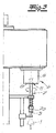
- die erfindungsgemäße kombinierte Motor-/Antriebseinheit schematisch im Schnitt,
- Fig. 2
- eine Anwendung der kombinierten Motor-/Antriebseinheit bei einer Behandlungsmaschine für Behälter, vorliegend einer Etikettiermaschine und
- Fig. 3
- einen anderen Anwendungsfall bei einer Behandlungsmaschine, die als Verschließmaschine ausgeführt ist.
- Fig. 1
- the combined motor / drive unit according to the invention schematically in section,
- Fig. 2
- an application of the combined motor / drive unit in a processing machine for containers, in this case a labeling and
- Fig. 3
- another application in a treatment machine, which is designed as a closing machine.
In den
Diese sämtlichen Behandlungen bzw. die einzelnen Behandlungsmaschinen zeichnen sich dadurch aus, dass eine Antriebseinheit 4 mit Antriebsmotor 5 und Motorgehäuse 6 realisiert ist. An die Antriebseinheit 4 ist eine Manipulationseinheit 7 angeschlossen. Bei der Manipulationseinheit 7 handelt es sich im Rahmen der Etikettiermaschine nach
Die Antriebseinheit 4 wird in einem Antriebsgehäuse 6 aufgenommen, weiches erfindungsgemäß zugleich das Motorgehäuse 6 ist. Zusätzlich weist die Antriebseinheit 4 wenigstens ein Lager 8 für die Manipulationseinheit 7 bzw. zu deren Anschluss auf.The
Im Rahmen des Ausführungsbeispiels handelt es sich bei dem Lager 8 um einen mit Hilfe des Antriebsmotors 5 rotativ angetriebenen Befestigungsflansch 8. Der Befestigungsflansch 8 ist zum unmittelbaren Anschluss der Manipulationseinheit 7 geeignet. Im Übrigen schließt der Befestigungsflansch 8 das zylindrische kombinierte Motor-/Antriebsgehäuse 6 kopfseitig in der Art eines Deckels ab. Tatsächlich ist die Manipulationseinheit 7 unmittelbar mit dem Befestigungsflansch 8 verbunden. Während das Motor-/Antriebsgehäuse 6 ortsfest ausgelegt und mit Hilfe eines Befestigungsankers 12 an einer nicht näher spezifizierten Basis festgelegt ist, rotiert demgegenüber der Befestigungsflansch 8, und zwar angetrieben mit Hilfe des Antriebsmotors 5.In the context of the exemplary embodiment, the
Wie bereits ausgeführt, übernimmt das Motorgehäuse 6 zugleich die Funktion des Antriebsgehäuses 6, d. h. Motorgehäuse 6 und Antriebsgehäuse 6 sind deckungsgleich und formen das kombinierte einzige Motor-/Antriebsgehäuse 6. Folgerichtig handelt es sich vorliegend um eine kombinierte Motor-/Antriebseinheit 4, 5 mit einzigem kombinierten Motor-/Antriebsgehäuse 6.As already stated, the motor housing 6 at the same time assumes the function of the drive housing 6, d. H. Motor housing 6 and drive housing 6 are congruent and form the combined single motor / drive housing 6. Consequently, this is a combined motor /
Im Innern des einzigen kombinierten Motor-/Antriebsgehäuse 6 findet sich neben dem Antriebsmotor 5 zusätzlich noch wenigstens ein Sensor 9. Mit Hilfe dieses lediglich in
Anhand der Schnittdarstellung in
Der Antriebsmotor 5 bzw. die kombinierte Motor-/Antriebseinheit 4, 5 mag mit einer zusätzlichen und nicht ausdrücklich dargestellten Kühlung, z. B. Wasserkühlung, ausgerüstet werden. Ebenso liegt es im Rahmen der Erfindung, für den Antriebsmotor 5 eine ergänzende Bremse vorzusehen. Sowohl die Kühlung als auch die Bremse werden in dem einzigen kombinierten Motor-/Antriebsgehäuse 6 aufgenommen.The
Als Antriebsmotor 5 kommt vorliegend ein Reluktanzmotor zum Einsatz, also ein Elektromotor, dessen Rotor 5a aus weichmagnetischem Material hergestellt ist bzw. solches Material in Gestalt von daran angebrachten Eisenmagneten im Beispielfall aufweist. Mit dem Rotor 5a ist der rotativ angetriebene Befestigungsflansch 8 und folglich auch die bereits angesprochene Antriebswelle für das Sternrad (
Zu dem Rotor 5a des Antriebsmotors 5 korrespondiert ein Stator 5b, welcher lediglich angedeutete Magnetspulen enthält. Die Funktionsweise des Reluktanzmotors ist vergleichbar mit derjenigen eines elektrischen Linearmotors. Tatsächlich wird in den Magnetspulen des Stators 5b ein Drehfeld erzeugt, welchem der Rotor 5a mit seinen Eisenmagneten folgt und sich synchron mit dem Drehfeld dreht. Als Folge hiervon wird auch der an den Rotor 5a angeschlossene Befestigungsflansch 8 in Drehungen versetzt, welchen die angeschlossene Manipulationseinheit 7 folgt.To the rotor 5a of the
Claims (6)
- Treatment machine for containers (1), such as bottles (1), cans, or the like, comprising at least one drive unit (4) with a drive motor (5) and motor housing (6), as well as a manipulation unit (7) that is connected to the drive unit (4), and with a drive housing (6), which receives the drive unit (4) and at least one bearing (8) for the manipulation unit (7), wherein- the motor housing (6) is also the drive housing (6) and forms a combined single motor/drive housing (6), and wherein- the motor/drive housing (6) comprises at least one securing flange (8) driven by the drive motor (5) as a bearing (8) for the direct connection of the manipulation unit (7),characterised in that- the drive motor (5) is formed as a reluctance motor with high dynamics and great flexibility in respect of its construction design, and covers a torque range of up to several 1000 Nm, and for this purpose is provided with a rotor (5a) and a stator (5b),- wherein the rotor (5a) has a pronounced pole made of a weakly magnetic material and- the corresponding stator (5b) contains the required magnetic coils, and wherein- the stator (5b) and the rotor (5a) of the drive motor (5) are formed in each case as hollow cylinders, and- as a result of this they define in their interiors a hollow drill hole (11) for the torsion-resistant coupling of a drive shaft of the manipulation unit (7).
- Treatment machine according to claim 1, characterised in that the combined motor/drive housing (6) receives, as well as the drive motor (5), at least one sensor (9), which detects motor characteristics and properties such as revolution speed, angle of rotation, temperature etc. of the drive motor (5).
- Treatment machine according to claim 1 or 2, characterised in that the securing flange (8) closes off the motor/drive housing (6) on the head side, in the form of a cover.
- Treatment machine according to any one of claims 1 to 3, characterised in that provision is additionally made for a cooling arrangement.
- Treatment machine according to any one of claims 1 to 4, characterised in that a brake is allocated to the drive motor (5).
- Use of an electric drive motor (5) with motor housing (6) as drive unit (4), with combined single motor/drive housing (6) for direct connection to a manipulation unit (7) in the course of the treatment of containers, such as bottles (1), cans, or the like, in associated treatment machines, wherein the motor/drive housing (6) comprises at least one securing flange (8) driven by the drive motor (5) as a bearing (8) for direct connection of the manipulation unit (7), and the drive motor (5) is formed as a reluctance motor with high dynamics and great flexibility in respect of its construction design, and covers a wide torque range of up to several 1000 Nm, and for this purpose is provided with a rotor (5a) and a stator (5b), wherein the rotor (5a) has a pronounced pole made of a weakly magnetic material, and the corresponding stator (5b) contains the required magnetic coils, and wherein the stator (5b) and the rotor (5a) of the drive motor (5) are in each case designed as hollow cylinders and, as a result, they define in their interiors a hollow drill hole (11) for the torsion-resistant coupling of a drive shaft of the manipulation unit (7).
Priority Applications (1)
| Application Number | Priority Date | Filing Date | Title |
|---|---|---|---|
| SI200831513T SI2155563T1 (en) | 2007-05-31 | 2008-05-29 | Machine having a direct drive for the treatment of containers |
Applications Claiming Priority (2)
| Application Number | Priority Date | Filing Date | Title |
|---|---|---|---|
| DE200710025522 DE102007025522A1 (en) | 2007-05-31 | 2007-05-31 | Direct drive machine for handling containers |
| PCT/EP2008/004267 WO2008145363A1 (en) | 2007-05-31 | 2008-05-29 | Machine having a direct drive for the treatment of containers |
Publications (2)
| Publication Number | Publication Date |
|---|---|
| EP2155563A1 EP2155563A1 (en) | 2010-02-24 |
| EP2155563B1 true EP2155563B1 (en) | 2015-09-16 |
Family
ID=39730854
Family Applications (1)
| Application Number | Title | Priority Date | Filing Date |
|---|---|---|---|
| EP08758850.5A Not-in-force EP2155563B1 (en) | 2007-05-31 | 2008-05-29 | Machine having a direct drive for the treatment of containers |
Country Status (8)
| Country | Link |
|---|---|
| EP (1) | EP2155563B1 (en) |
| JP (1) | JP5449141B2 (en) |
| CN (1) | CN101678910B (en) |
| BR (1) | BRPI0813106A2 (en) |
| DE (1) | DE102007025522A1 (en) |
| RU (1) | RU2429171C1 (en) |
| SI (1) | SI2155563T1 (en) |
| WO (1) | WO2008145363A1 (en) |
Families Citing this family (19)
| Publication number | Priority date | Publication date | Assignee | Title |
|---|---|---|---|---|
| DE102008038146A1 (en) * | 2008-08-18 | 2010-02-25 | Krones Ag | Device for handling container e.g. bottle sealing machine, has shaft drive system with coaxial direct drive containing motor, in which rotor is directly fixed on machine shaft, and stator including shaft and rotor are fixed on exterior side |
| DE102009009822A1 (en) * | 2009-02-20 | 2010-08-26 | Krones Ag | Device for closing containers with non-contact torque generation |
| DE202009019170U1 (en) | 2009-09-07 | 2017-07-07 | Krones Ag | Device for producing plastic bottles |
| DE102009055301A1 (en) | 2009-12-23 | 2011-06-30 | Krones Ag, 93073 | container transporter |
| DE102010027337A1 (en) | 2010-07-15 | 2012-01-19 | Khs Gmbh | Treatment machine for containers |
| DE102011003118A1 (en) | 2011-01-25 | 2012-07-26 | Krones Aktiengesellschaft | closing |
| DE102011103837A1 (en) | 2011-06-01 | 2012-12-06 | Khs Gmbh | Treatment machine for containers |
| JP5500144B2 (en) | 2011-09-07 | 2014-05-21 | 株式会社安川電機 | Rotating electric machine |
| DE102012000881A1 (en) | 2011-12-14 | 2013-06-20 | Khs Gmbh | Treatment machine e.g. rotary type closing machine for container such as bottle, has head plate at upper end of central column, which is arranged to receive interacting elements with rotor, and transfer elements are held at head plate |
| EP2610187B1 (en) * | 2011-12-30 | 2016-12-28 | Krones AG | Device for transferring fitting pieces for container labelling |
| DE102012204721A1 (en) * | 2012-03-23 | 2013-09-26 | Schaeffler Technologies AG & Co. KG | Direct drive for a rotary machine, in particular for a container treatment machine |
| DE102012209905A1 (en) * | 2012-06-13 | 2013-12-19 | Krones Ag | Capper for containers |
| DE102012209970A1 (en) * | 2012-06-14 | 2013-12-19 | Krones Ag | Circulating air radiator for beverage filling system, has rolling device arranged in pillar such that air surrounds electromotive drive unit and circulates within pillar, where rolling device is provided with drivable fan |
| DE102013218438A1 (en) * | 2013-09-13 | 2015-03-19 | Krones Ag | Rotary machine with direct drive |
| CN104743345B (en) * | 2013-12-31 | 2017-05-17 | 楚天科技股份有限公司 | Method and device for conveying bottles arrayed in double rows |
| DE102014100733A1 (en) * | 2014-01-23 | 2015-07-23 | Krones Ag | Cooling system for container treatment plants |
| JP6785691B2 (en) | 2017-03-13 | 2020-11-18 | 住友重機械工業株式会社 | Drive device |
| DE102019119596A1 (en) * | 2019-07-19 | 2021-01-21 | Khs Gmbh | Filling machine for filling containers with a liquid filling material and method for cooling a drive and / or gear unit of a filling machine |
| CN111646419B (en) * | 2020-06-09 | 2021-07-16 | 王锦 | Biological reagent's dress gets device |
Family Cites Families (14)
| Publication number | Priority date | Publication date | Assignee | Title |
|---|---|---|---|---|
| DE1970339U (en) | 1967-07-17 | 1967-10-12 | Rheinische Draht Und Kabelwerk | WELDING TONGS. |
| JPH0297248A (en) * | 1988-09-08 | 1990-04-09 | Ntn Corp | Dd motor associated with rotary angle detecting mechanism |
| US5281296A (en) * | 1991-07-30 | 1994-01-25 | Markem Corporation | Label applicator |
| DE9217784U1 (en) * | 1992-12-29 | 1993-04-08 | Schneider, Friedhelm, 5226 Reichshof, De | |
| DE19703369A1 (en) | 1997-01-30 | 1998-08-06 | Khs Masch & Anlagenbau Ag | Device for transporting vessels |
| DE29724886U1 (en) * | 1997-09-15 | 2005-04-14 | Krones Ag | Transport and handling system for bottles in factory has input star wheel removing bottles from input conveyer and output star wheel returning bottles to conveyer after processing |
| JP4196433B2 (en) * | 1998-07-09 | 2008-12-17 | 日本精工株式会社 | Sealed actuator |
| IT1304700B1 (en) * | 1998-12-23 | 2001-03-28 | Antas S P A | EQUIPMENT FOR GLASS WORKING WITH A PERFORATED ROUNDING SYSTEM AND ITS CONTROL METHOD |
| DE10034907A1 (en) | 2000-07-18 | 2002-01-31 | Khs Masch & Anlagenbau Ag | Machine for handling bottles, cans or similar containers |
| DE10352016B3 (en) | 2003-11-07 | 2005-08-11 | Khs Maschinen- Und Anlagenbau Ag | Closing machine for closing vessels |
| DE102004024136B4 (en) * | 2004-05-14 | 2023-08-10 | Khs Gmbh | Drive motor with integrated shaft connection elements |
| DE102004026755A1 (en) * | 2004-05-29 | 2005-12-22 | Krones Ag | Machine for aligning and equipping objects |
| ES2391571T3 (en) * | 2006-06-06 | 2012-11-27 | Sidel Holdings & Technology S.A. | Motor-plate unit in a labeling machine |
| DE102006039090A1 (en) * | 2006-08-19 | 2008-02-21 | Khs Ag | Drive for rotary machines |
-
2007
- 2007-05-31 DE DE200710025522 patent/DE102007025522A1/en not_active Withdrawn
-
2008
- 2008-05-29 SI SI200831513T patent/SI2155563T1/en unknown
- 2008-05-29 EP EP08758850.5A patent/EP2155563B1/en not_active Not-in-force
- 2008-05-29 JP JP2010509733A patent/JP5449141B2/en not_active Expired - Fee Related
- 2008-05-29 CN CN200880017484.3A patent/CN101678910B/en not_active Expired - Fee Related
- 2008-05-29 BR BRPI0813106A patent/BRPI0813106A2/en not_active Application Discontinuation
- 2008-05-29 RU RU2009149433/12A patent/RU2429171C1/en not_active IP Right Cessation
- 2008-05-29 WO PCT/EP2008/004267 patent/WO2008145363A1/en active Application Filing
Also Published As
| Publication number | Publication date |
|---|---|
| EP2155563A1 (en) | 2010-02-24 |
| JP2010527858A (en) | 2010-08-19 |
| DE102007025522A1 (en) | 2008-12-04 |
| CN101678910B (en) | 2013-12-18 |
| CN101678910A (en) | 2010-03-24 |
| RU2429171C1 (en) | 2011-09-20 |
| WO2008145363A1 (en) | 2008-12-04 |
| SI2155563T1 (en) | 2015-11-30 |
| BRPI0813106A2 (en) | 2018-06-05 |
| RU2009149433A (en) | 2011-07-10 |
| JP5449141B2 (en) | 2014-03-19 |
Similar Documents
| Publication | Publication Date | Title |
|---|---|---|
| EP2155563B1 (en) | Machine having a direct drive for the treatment of containers | |
| EP2338813B1 (en) | Container transporter | |
| EP1529751B1 (en) | Machine for closing containers | |
| EP2479136A2 (en) | Locking device | |
| DE102007057857A1 (en) | Device for closing containers | |
| DE2151916A1 (en) | Magnetic storage | |
| DE202004021791U1 (en) | Machine for aligning and equipping objects | |
| EP2387534A2 (en) | Container treatment machine | |
| DE10024327A1 (en) | Drive for rotating part of printer has motor locally variable by servo drive in direction with component parallel to rotary axis of rotating part | |
| EP2105404A2 (en) | Table for container handling machines and container handling machine | |
| DE102009023079A1 (en) | Rotary table | |
| EP1082225B1 (en) | Roller for a rotary press | |
| EP0689277B1 (en) | Electro-motor for driving a rotational body | |
| EP2714528B1 (en) | Handling machine for containers | |
| DE102012000881A1 (en) | Treatment machine e.g. rotary type closing machine for container such as bottle, has head plate at upper end of central column, which is arranged to receive interacting elements with rotor, and transfer elements are held at head plate | |
| EP1728574A1 (en) | Clamping device for a machine tool | |
| EP2576418B1 (en) | Device for processing a product, having an element for processing the product | |
| EP3319754A1 (en) | Drive arrangement for a swivel bridge | |
| EP2593370B1 (en) | Machine for handling containers | |
| EP2632704B1 (en) | Mechanical metal-forming machine, in particular a crank press, and method for providing a mechanical metal-forming machine | |
| DE102008061848A1 (en) | Apparatus and method for closing containers with a closure | |
| DE3844288C1 (en) | ||
| DE10032815A1 (en) | Folding cylinder of folding apparatus has each of folding components driven with separate drive that is supplied via rotary lead-through and controlled by speed controller | |
| EP2490894A1 (en) | Devices in a printing couple of a printing machine | |
| DD275222A1 (en) | DEVICE FOR RETRIEVING LABELS |
Legal Events
| Date | Code | Title | Description |
|---|---|---|---|
| PUAI | Public reference made under article 153(3) epc to a published international application that has entered the european phase |
Free format text: ORIGINAL CODE: 0009012 |
|
| 17P | Request for examination filed |
Effective date: 20100104 |
|
| AK | Designated contracting states |
Kind code of ref document: A1 Designated state(s): AT BE BG CH CY CZ DE DK EE ES FI FR GB GR HR HU IE IS IT LI LT LU LV MC MT NL NO PL PT RO SE SI SK TR |
|
| AX | Request for extension of the european patent |
Extension state: AL BA MK RS |
|
| RAP1 | Party data changed (applicant data changed or rights of an application transferred) |
Owner name: KHS GMBH Owner name: SCHAEFFLER KG Owner name: INA DRIVES & MECHATRONIC GMBH & CO. OHG |
|
| DAX | Request for extension of the european patent (deleted) | ||
| 17Q | First examination report despatched |
Effective date: 20100916 |
|
| RAP1 | Party data changed (applicant data changed or rights of an application transferred) |
Owner name: KHS GMBH Owner name: INA DRIVES & MECHATRONIC GMBH & CO. OHG Owner name: SCHAEFFLER TECHNOLOGIES AG & CO. KG |
|
| RAP1 | Party data changed (applicant data changed or rights of an application transferred) |
Owner name: SCHAEFFLER TECHNOLOGIES AG & CO. KG Owner name: KHS GMBH |
|
| RAP1 | Party data changed (applicant data changed or rights of an application transferred) |
Owner name: KHS GMBH Owner name: SCHAEFFLER TECHNOLOGIES GMBH & CO. KG |
|
| RAP1 | Party data changed (applicant data changed or rights of an application transferred) |
Owner name: KHS GMBH Owner name: SCHAEFFLER TECHNOLOGIES AG & CO. KG |
|
| GRAP | Despatch of communication of intention to grant a patent |
Free format text: ORIGINAL CODE: EPIDOSNIGR1 |
|
| INTG | Intention to grant announced |
Effective date: 20150625 |
|
| GRAS | Grant fee paid |
Free format text: ORIGINAL CODE: EPIDOSNIGR3 |
|
| GRAA | (expected) grant |
Free format text: ORIGINAL CODE: 0009210 |
|
| AK | Designated contracting states |
Kind code of ref document: B1 Designated state(s): AT BE BG CH CY CZ DE DK EE ES FI FR GB GR HR HU IE IS IT LI LT LU LV MC MT NL NO PL PT RO SE SI SK TR |
|
| REG | Reference to a national code |
Ref country code: GB Ref legal event code: FG4D Free format text: NOT ENGLISH |
|
| REG | Reference to a national code |
Ref country code: CH Ref legal event code: NV Representative=s name: E. BLUM AND CO. AG PATENT- UND MARKENANWAELTE , CH Ref country code: CH Ref legal event code: EP |
|
| REG | Reference to a national code |
Ref country code: IE Ref legal event code: FG4D Free format text: LANGUAGE OF EP DOCUMENT: GERMAN |
|
| REG | Reference to a national code |
Ref country code: AT Ref legal event code: REF Ref document number: 749596 Country of ref document: AT Kind code of ref document: T Effective date: 20151015 |
|
| REG | Reference to a national code |
Ref country code: DE Ref legal event code: R096 Ref document number: 502008013388 Country of ref document: DE |
|
| REG | Reference to a national code |
Ref country code: NL Ref legal event code: MP Effective date: 20150916 |
|
| PG25 | Lapsed in a contracting state [announced via postgrant information from national office to epo] |
Ref country code: FI Free format text: LAPSE BECAUSE OF FAILURE TO SUBMIT A TRANSLATION OF THE DESCRIPTION OR TO PAY THE FEE WITHIN THE PRESCRIBED TIME-LIMIT Effective date: 20150916 Ref country code: LV Free format text: LAPSE BECAUSE OF FAILURE TO SUBMIT A TRANSLATION OF THE DESCRIPTION OR TO PAY THE FEE WITHIN THE PRESCRIBED TIME-LIMIT Effective date: 20150916 Ref country code: GR Free format text: LAPSE BECAUSE OF FAILURE TO SUBMIT A TRANSLATION OF THE DESCRIPTION OR TO PAY THE FEE WITHIN THE PRESCRIBED TIME-LIMIT Effective date: 20151217 Ref country code: NO Free format text: LAPSE BECAUSE OF FAILURE TO SUBMIT A TRANSLATION OF THE DESCRIPTION OR TO PAY THE FEE WITHIN THE PRESCRIBED TIME-LIMIT Effective date: 20151216 Ref country code: LT Free format text: LAPSE BECAUSE OF FAILURE TO SUBMIT A TRANSLATION OF THE DESCRIPTION OR TO PAY THE FEE WITHIN THE PRESCRIBED TIME-LIMIT Effective date: 20150916 |
|
| REG | Reference to a national code |
Ref country code: LT Ref legal event code: MG4D |
|
| PG25 | Lapsed in a contracting state [announced via postgrant information from national office to epo] |
Ref country code: HR Free format text: LAPSE BECAUSE OF FAILURE TO SUBMIT A TRANSLATION OF THE DESCRIPTION OR TO PAY THE FEE WITHIN THE PRESCRIBED TIME-LIMIT Effective date: 20150916 Ref country code: SE Free format text: LAPSE BECAUSE OF FAILURE TO SUBMIT A TRANSLATION OF THE DESCRIPTION OR TO PAY THE FEE WITHIN THE PRESCRIBED TIME-LIMIT Effective date: 20150916 |
|
| PG25 | Lapsed in a contracting state [announced via postgrant information from national office to epo] |
Ref country code: NL Free format text: LAPSE BECAUSE OF FAILURE TO SUBMIT A TRANSLATION OF THE DESCRIPTION OR TO PAY THE FEE WITHIN THE PRESCRIBED TIME-LIMIT Effective date: 20150916 |
|
| PG25 | Lapsed in a contracting state [announced via postgrant information from national office to epo] |
Ref country code: SK Free format text: LAPSE BECAUSE OF FAILURE TO SUBMIT A TRANSLATION OF THE DESCRIPTION OR TO PAY THE FEE WITHIN THE PRESCRIBED TIME-LIMIT Effective date: 20150916 Ref country code: EE Free format text: LAPSE BECAUSE OF FAILURE TO SUBMIT A TRANSLATION OF THE DESCRIPTION OR TO PAY THE FEE WITHIN THE PRESCRIBED TIME-LIMIT Effective date: 20150916 Ref country code: CZ Free format text: LAPSE BECAUSE OF FAILURE TO SUBMIT A TRANSLATION OF THE DESCRIPTION OR TO PAY THE FEE WITHIN THE PRESCRIBED TIME-LIMIT Effective date: 20150916 Ref country code: IS Free format text: LAPSE BECAUSE OF FAILURE TO SUBMIT A TRANSLATION OF THE DESCRIPTION OR TO PAY THE FEE WITHIN THE PRESCRIBED TIME-LIMIT Effective date: 20160116 Ref country code: ES Free format text: LAPSE BECAUSE OF FAILURE TO SUBMIT A TRANSLATION OF THE DESCRIPTION OR TO PAY THE FEE WITHIN THE PRESCRIBED TIME-LIMIT Effective date: 20150916 |
|
| REG | Reference to a national code |
Ref country code: FR Ref legal event code: PLFP Year of fee payment: 9 |
|
| PG25 | Lapsed in a contracting state [announced via postgrant information from national office to epo] |
Ref country code: PL Free format text: LAPSE BECAUSE OF FAILURE TO SUBMIT A TRANSLATION OF THE DESCRIPTION OR TO PAY THE FEE WITHIN THE PRESCRIBED TIME-LIMIT Effective date: 20150916 Ref country code: PT Free format text: LAPSE BECAUSE OF FAILURE TO SUBMIT A TRANSLATION OF THE DESCRIPTION OR TO PAY THE FEE WITHIN THE PRESCRIBED TIME-LIMIT Effective date: 20160118 Ref country code: RO Free format text: LAPSE BECAUSE OF FAILURE TO SUBMIT A TRANSLATION OF THE DESCRIPTION OR TO PAY THE FEE WITHIN THE PRESCRIBED TIME-LIMIT Effective date: 20150916 |
|
| REG | Reference to a national code |
Ref country code: DE Ref legal event code: R097 Ref document number: 502008013388 Country of ref document: DE |
|
| PLBE | No opposition filed within time limit |
Free format text: ORIGINAL CODE: 0009261 |
|
| STAA | Information on the status of an ep patent application or granted ep patent |
Free format text: STATUS: NO OPPOSITION FILED WITHIN TIME LIMIT |
|
| 26N | No opposition filed |
Effective date: 20160617 |
|
| PG25 | Lapsed in a contracting state [announced via postgrant information from national office to epo] |
Ref country code: DK Free format text: LAPSE BECAUSE OF FAILURE TO SUBMIT A TRANSLATION OF THE DESCRIPTION OR TO PAY THE FEE WITHIN THE PRESCRIBED TIME-LIMIT Effective date: 20150916 Ref country code: BE Free format text: LAPSE BECAUSE OF NON-PAYMENT OF DUE FEES Effective date: 20160531 |
|
| PG25 | Lapsed in a contracting state [announced via postgrant information from national office to epo] |
Ref country code: LU Free format text: LAPSE BECAUSE OF FAILURE TO SUBMIT A TRANSLATION OF THE DESCRIPTION OR TO PAY THE FEE WITHIN THE PRESCRIBED TIME-LIMIT Effective date: 20160529 |
|
| GBPC | Gb: european patent ceased through non-payment of renewal fee |
Effective date: 20160529 |
|
| REG | Reference to a national code |
Ref country code: IE Ref legal event code: MM4A |
|
| REG | Reference to a national code |
Ref country code: FR Ref legal event code: PLFP Year of fee payment: 10 |
|
| PG25 | Lapsed in a contracting state [announced via postgrant information from national office to epo] |
Ref country code: IE Free format text: LAPSE BECAUSE OF NON-PAYMENT OF DUE FEES Effective date: 20160529 Ref country code: GB Free format text: LAPSE BECAUSE OF NON-PAYMENT OF DUE FEES Effective date: 20160529 |
|
| REG | Reference to a national code |
Ref country code: FR Ref legal event code: PLFP Year of fee payment: 11 |
|
| PG25 | Lapsed in a contracting state [announced via postgrant information from national office to epo] |
Ref country code: CY Free format text: LAPSE BECAUSE OF FAILURE TO SUBMIT A TRANSLATION OF THE DESCRIPTION OR TO PAY THE FEE WITHIN THE PRESCRIBED TIME-LIMIT Effective date: 20150916 Ref country code: HU Free format text: LAPSE BECAUSE OF FAILURE TO SUBMIT A TRANSLATION OF THE DESCRIPTION OR TO PAY THE FEE WITHIN THE PRESCRIBED TIME-LIMIT; INVALID AB INITIO Effective date: 20080529 |
|
| PG25 | Lapsed in a contracting state [announced via postgrant information from national office to epo] |
Ref country code: TR Free format text: LAPSE BECAUSE OF FAILURE TO SUBMIT A TRANSLATION OF THE DESCRIPTION OR TO PAY THE FEE WITHIN THE PRESCRIBED TIME-LIMIT Effective date: 20150916 Ref country code: MT Free format text: LAPSE BECAUSE OF FAILURE TO SUBMIT A TRANSLATION OF THE DESCRIPTION OR TO PAY THE FEE WITHIN THE PRESCRIBED TIME-LIMIT Effective date: 20150916 Ref country code: MC Free format text: LAPSE BECAUSE OF FAILURE TO SUBMIT A TRANSLATION OF THE DESCRIPTION OR TO PAY THE FEE WITHIN THE PRESCRIBED TIME-LIMIT Effective date: 20150916 |
|
| PG25 | Lapsed in a contracting state [announced via postgrant information from national office to epo] |
Ref country code: BG Free format text: LAPSE BECAUSE OF FAILURE TO SUBMIT A TRANSLATION OF THE DESCRIPTION OR TO PAY THE FEE WITHIN THE PRESCRIBED TIME-LIMIT Effective date: 20150916 |
|
| PGFP | Annual fee paid to national office [announced via postgrant information from national office to epo] |
Ref country code: DE Payment date: 20180522 Year of fee payment: 11 Ref country code: CH Payment date: 20180523 Year of fee payment: 11 |
|
| PGFP | Annual fee paid to national office [announced via postgrant information from national office to epo] |
Ref country code: IT Payment date: 20180530 Year of fee payment: 11 Ref country code: AT Payment date: 20180522 Year of fee payment: 11 Ref country code: FR Payment date: 20180522 Year of fee payment: 11 Ref country code: SI Payment date: 20180504 Year of fee payment: 11 |
|
| REG | Reference to a national code |
Ref country code: DE Ref legal event code: R119 Ref document number: 502008013388 Country of ref document: DE |
|
| REG | Reference to a national code |
Ref country code: CH Ref legal event code: PL |
|
| REG | Reference to a national code |
Ref country code: AT Ref legal event code: MM01 Ref document number: 749596 Country of ref document: AT Kind code of ref document: T Effective date: 20190529 |
|
| PG25 | Lapsed in a contracting state [announced via postgrant information from national office to epo] |
Ref country code: AT Free format text: LAPSE BECAUSE OF NON-PAYMENT OF DUE FEES Effective date: 20190529 Ref country code: LI Free format text: LAPSE BECAUSE OF NON-PAYMENT OF DUE FEES Effective date: 20190531 Ref country code: CH Free format text: LAPSE BECAUSE OF NON-PAYMENT OF DUE FEES Effective date: 20190531 |
|
| PG25 | Lapsed in a contracting state [announced via postgrant information from national office to epo] |
Ref country code: SI Free format text: LAPSE BECAUSE OF NON-PAYMENT OF DUE FEES Effective date: 20190530 |
|
| PG25 | Lapsed in a contracting state [announced via postgrant information from national office to epo] |
Ref country code: IT Free format text: LAPSE BECAUSE OF NON-PAYMENT OF DUE FEES Effective date: 20190529 Ref country code: DE Free format text: LAPSE BECAUSE OF NON-PAYMENT OF DUE FEES Effective date: 20191203 |
|
| PG25 | Lapsed in a contracting state [announced via postgrant information from national office to epo] |
Ref country code: FR Free format text: LAPSE BECAUSE OF NON-PAYMENT OF DUE FEES Effective date: 20190531 |