EP2479136A2 - Dispositif de verrouillage - Google Patents
Dispositif de verrouillage Download PDFInfo
- Publication number
- EP2479136A2 EP2479136A2 EP11194296A EP11194296A EP2479136A2 EP 2479136 A2 EP2479136 A2 EP 2479136A2 EP 11194296 A EP11194296 A EP 11194296A EP 11194296 A EP11194296 A EP 11194296A EP 2479136 A2 EP2479136 A2 EP 2479136A2
- Authority
- EP
- European Patent Office
- Prior art keywords
- closing
- drive
- closing device
- gear member
- gear
- Prior art date
- Legal status (The legal status is an assumption and is not a legal conclusion. Google has not performed a legal analysis and makes no representation as to the accuracy of the status listed.)
- Withdrawn
Links
Images
Classifications
-
- B—PERFORMING OPERATIONS; TRANSPORTING
- B67—OPENING, CLOSING OR CLEANING BOTTLES, JARS OR SIMILAR CONTAINERS; LIQUID HANDLING
- B67B—APPLYING CLOSURE MEMBERS TO BOTTLES JARS, OR SIMILAR CONTAINERS; OPENING CLOSED CONTAINERS
- B67B3/00—Closing bottles, jars or similar containers by applying caps
- B67B3/20—Closing bottles, jars or similar containers by applying caps by applying and rotating preformed threaded caps
- B67B3/2013—Closing bottles, jars or similar containers by applying caps by applying and rotating preformed threaded caps by carousel-type capping machines
- B67B3/2033—Closing bottles, jars or similar containers by applying caps by applying and rotating preformed threaded caps by carousel-type capping machines comprising carousel co-rotating capping heads
-
- B—PERFORMING OPERATIONS; TRANSPORTING
- B67—OPENING, CLOSING OR CLEANING BOTTLES, JARS OR SIMILAR CONTAINERS; LIQUID HANDLING
- B67B—APPLYING CLOSURE MEMBERS TO BOTTLES JARS, OR SIMILAR CONTAINERS; OPENING CLOSED CONTAINERS
- B67B3/00—Closing bottles, jars or similar containers by applying caps
- B67B3/02—Closing bottles, jars or similar containers by applying caps by applying flanged caps, e.g. crown caps, and securing by deformation of flanges
- B67B3/10—Capping heads for securing caps
- B67B3/18—Capping heads for securing caps characterised by being rotatable, e.g. for forming screw threads in situ
Definitions
- the invention relates to a closure device for containers explained in the preamble of claim 1 Art.
- Such a closing device is for example from the EP-A-1 103 513 known.
- the known closing device is part of a filling system for beverage containers, in particular bottles, and contains a supporting center column, which is driven in rotation by a drive about a vertical axis.
- brackets for the container and each associated with each holder closing unit are arranged, which rotate with the center column about the vertical axis.
- a stationary frame is further provided, to which a lifting cam is mounted, on which the closing unit rolls with a roller arrangement such that a predetermined lifting movement of the closing unit can take place along the extended center line of the container, so that a closure from above the container can be placed.
- a rotary drive for the closing unit is further provided, with the aid of which, for example, screw caps can be screwed onto the container.
- the rotary drive includes a first gear member in the form of a gear which is rotatably mounted on the stationary frame.
- a second gear member in the form of a gear is located on the circumference of the closing unit and moves with this around the vertical axis of the column. Both gear members are engaged with each other, so that the gear members roll on each other and the closing unit is thereby rotated.
- the drive of the closing unit is thus derived from the drive of the transport device. However, this determines the direction of rotation and the speed of rotation. In addition, this type of drive requires extensive conversion measures when special user needs must be addressed.
- the invention is therefore based on the object to provide a closing device that provides a structurally simple way greater flexibility in the fulfillment of user wishes of the closing.
- the advantages of the transmission elements with respect to a simple construction and a functionally reliable, robust design are maintained, but increases the flexibility by a separate drive of the first of the transmission links.
- the drive can be used to adjust the speed to the particular screw cap used and the torque to the material of the screw cap and container, as well as rotational movements in both directions are easily possible.
- Torque motors are relatively compact, so that their runner may have a smaller outer diameter than the pitch circle of the holders of the container in the closing device and thus allows a compact design.
- the drive especially when using a hollow shaft motor, can easily sit on the rotating column, which acts as a drive for the transport device.
- the torque motor thus moves together with the column and independently, so that in a simple way changes in the transport speed can be included in the drive speed of the closing device.
- gear members As gear members, the proven gears can be used, friction wheels or the like. However, are also possible.
- one of the gear members is extended so that the engagement is maintained throughout the length of the linear motion.
- closure unit in a modular manner, wherein the various functions are combined into one assembly, so that for example Matching different rotary assemblies with the same lift assembly or different lift assemblies with the same rotary assembly and can be replaced depending on the type of container to be handled by the user.
- the closing unit can also have a replaceable closing head, which is adapted to different closure constructions.
- the closing units can be kept ready for any type of container or closure and, if appropriate, also provided for retrofitting already in operation closing devices.
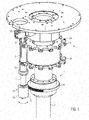
- Fig. 1 shows a perspective, schematic partial representation of a closing device 1 of substantially conventional design.
- the closing device 1 comprises a vertical center column 2, which comprises an inner, non-stationary but height-resistant support 3 and an outer, about its vertical center line 4 'driven rotary sleeve 4.
- the holders for the container and a holder 5 for at least one closing unit 6 are mounted in a conventional and not shown manner.
- the holder 5 contains in the illustrated embodiment, two superimposed pitch circles 5a and 5b hold the closing units 6 in circumferential distance from each other.
- a stationary head plate 7 On which a lifting cam 9 is arranged on a downwardly projecting flange 8, in which in a known manner a roller 10 engages, which is rotatably mounted on the closing unit 6.
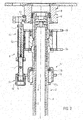
- a lifting cylinder 11 With the roller 10, a lifting cylinder 11 is connected, in a guide sleeve 12 in the vertical direction, ie in the direction of the aligned center lines 11 'of the lifting cylinder 11 and the center line 13' a container 13 ( Fig. 3 ) is arranged displaceably.
- the guide sleeve 12 is connected to the holder 5.
- Roller 10 and lifting cylinder 11 form a hub assembly 14th
- the stroke can also be carried out by electric motor or pneumatically
- a rotary assembly 15 is rotatably mounted about the central axis 11 'of the lifting cylinder 11. The attachment is made such that the two assemblies 14 and 15 are interchangeable attached to each other.
- the rotary assembly 15 includes a sleeve-shaped carrier 16, which on the lifting cylinder 11 facing away from the lower end either a fixed locking head or a clutch which is able to interchangeably absorb different Verschetzkopftypen.
- the drive via a hollow shaft motor, in particular a so-called torque motor in the hollow shaft design, which sits without connection with the lifting cam 9, with its hollow stator 17a on the rotary sleeve 4 of the central column 2 and rotates with this about the center line 4 ', and an external rotor 17b, which is provided on its outside with a first gear member 18 in the form of a gear, a pinion or a ring gear, which extends coaxially about the center line 4 'of the rotary sleeve 4.
- Engine and storage form a single unit.
- This first gear member 18 of the drive 17 drives the rotary assembly 15 in the desired direction of rotation separately and independently of the drive of the rotary sleeve 4 of the central column 2 via a second gear member 19.
- the second gear member 19 is also a gear, but has an axial length in the direction of the center line 11 ', which is greater than the axial length of the first gear member 18 and at least as large as that caused by the lifting cam 4 stroke of the lifting cylinder 11, so that in each stage of the lifting movement of the drive 17 acts on the rotary assembly 15.
- the second gear member 19 is fixed in the illustrated embodiment on the outside of the sleeve 16
- the control of the drive 17 and its power supply via cables which preferably extend in the interior of the central column 2, and for example a slip ring transmitter, or contactless.
- the closing device according to the invention can be adapted in a structurally simple manner to certain user requirements, be it already during manufacture, be it for retrofitting.
- the Wegemesssystem can detect the speed of the capping head and optionally regulate what z.
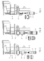
- Fig. 3 to 5 show various possibilities of application of the closing device according to the invention.
- Fig. 3 shows the use of the closure device according to the invention for applying screw caps.
- the container 13 is aligned with its center line 13 'in alignment with the center line 11' of the lifting cylinder and a capping head 20 for applying screw caps or a Greiferverschmonykopf or the like.
- the central column 2 is driven and the drive 17 set in motion to actuate the assemblies of the closing unit 6 by a combined linear movement in the height direction (stroke) and rotational movement about the vertical axis 11 'for screwing the screw cap on the container 13.
- Fig. 4 shows a closing device according to the invention for applying Aluanrollver whiln on container 13. Like Fig. 4 shows, the closing device corresponds to Fig. 4 the closing device according to Fig. 3 with regard to the hub assembly 14 and the rotary assembly 15. What has been changed is only the capping head, which has been replaced by an aluminum rolling head 21 capable of applying these aluminum roller shutters.
- Fig. 5 shows a closing device according to the invention equipped for applying crown corks.
- the closure unit here includes the lift assembly 14 while the rotary assembly has been removed and a crown cork capping head 22 or aluminum sealing head or the like has been directly attached to the lift assembly 14.
- the drive 17 is thus shut down, can however, remain in place if further conversion to screw caps is expected.
- the closing unit can also be designed with a head drive, preferably when the modular or assembly structure is not necessary.
- This is also the rotary or screw drive above the holder for the container.
- the torque motor can be easily encapsulated, d. H. be housed in a protective housing that leaves only the sprocket so that the cleaning is greatly facilitated.
- other motors can preferably be used with a hollow shaft.
- the two gear members do not necessarily directly engage with each other, intermediate links may also be provided.
- the described drive can also be provided without a separate drive in Verschnoviseren without module division, and the module blocks.
Landscapes
- Engineering & Computer Science (AREA)
- Mechanical Engineering (AREA)
- Sealing Of Jars (AREA)
- Connection Of Motors, Electrical Generators, Mechanical Devices, And The Like (AREA)
- Transmission Devices (AREA)
Applications Claiming Priority (1)
| Application Number | Priority Date | Filing Date | Title |
|---|---|---|---|
| DE102011003118A DE102011003118A1 (de) | 2011-01-25 | 2011-01-25 | Verschließeinrichtung |
Publications (2)
| Publication Number | Publication Date |
|---|---|
| EP2479136A2 true EP2479136A2 (fr) | 2012-07-25 |
| EP2479136A3 EP2479136A3 (fr) | 2012-10-17 |
Family
ID=45444427
Family Applications (1)
| Application Number | Title | Priority Date | Filing Date |
|---|---|---|---|
| EP11194296A Withdrawn EP2479136A3 (fr) | 2011-01-25 | 2011-12-19 | Dispositif de verrouillage |
Country Status (4)
| Country | Link |
|---|---|
| US (1) | US20120186194A1 (fr) |
| EP (1) | EP2479136A3 (fr) |
| CN (1) | CN102616708B (fr) |
| DE (1) | DE102011003118A1 (fr) |
Cited By (2)
| Publication number | Priority date | Publication date | Assignee | Title |
|---|---|---|---|---|
| IT202200018609A1 (it) * | 2022-09-12 | 2024-03-12 | Arol Spa | Gruppo di chiusura per testa di tappatura di una macchina tappatrice |
| IT202200018603A1 (it) * | 2022-09-12 | 2024-03-12 | Arol Spa | Gruppo di chiusura per testa di tappatura per macchina tappatrice e macchina tappatrice |
Families Citing this family (40)
| Publication number | Priority date | Publication date | Assignee | Title |
|---|---|---|---|---|
| US8414505B1 (en) | 2001-02-15 | 2013-04-09 | Hansen Medical, Inc. | Catheter driver system |
| DE102009045637A1 (de) * | 2009-10-13 | 2011-04-14 | Krones Ag | Verfahren und Vorrichtung zum Schraubverschließen von Gefäßen, insbesondere Flaschen |
| US20130317519A1 (en) | 2012-05-25 | 2013-11-28 | Hansen Medical, Inc. | Low friction instrument driver interface for robotic systems |
| US9668814B2 (en) | 2013-03-07 | 2017-06-06 | Hansen Medical, Inc. | Infinitely rotatable tool with finite rotating drive shafts |
| US20140277334A1 (en) | 2013-03-14 | 2014-09-18 | Hansen Medical, Inc. | Active drives for robotic catheter manipulators |
| US11213363B2 (en) | 2013-03-14 | 2022-01-04 | Auris Health, Inc. | Catheter tension sensing |
| US9173713B2 (en) | 2013-03-14 | 2015-11-03 | Hansen Medical, Inc. | Torque-based catheter articulation |
| US9498601B2 (en) | 2013-03-14 | 2016-11-22 | Hansen Medical, Inc. | Catheter tension sensing |
| US9326822B2 (en) | 2013-03-14 | 2016-05-03 | Hansen Medical, Inc. | Active drives for robotic catheter manipulators |
| US20140276936A1 (en) | 2013-03-15 | 2014-09-18 | Hansen Medical, Inc. | Active drive mechanism for simultaneous rotation and translation |
| US9408669B2 (en) | 2013-03-15 | 2016-08-09 | Hansen Medical, Inc. | Active drive mechanism with finite range of motion |
| US20140276647A1 (en) | 2013-03-15 | 2014-09-18 | Hansen Medical, Inc. | Vascular remote catheter manipulator |
| US9452018B2 (en) | 2013-03-15 | 2016-09-27 | Hansen Medical, Inc. | Rotational support for an elongate member |
| US9980785B2 (en) * | 2013-10-24 | 2018-05-29 | Auris Health, Inc. | Instrument device manipulator with surgical tool de-articulation |
| EP3060157B1 (fr) | 2013-10-24 | 2019-12-11 | Auris Health, Inc. | Système pour chirurgie endoluminale assistée par la robotique |
| US10046140B2 (en) | 2014-04-21 | 2018-08-14 | Hansen Medical, Inc. | Devices, systems, and methods for controlling active drive systems |
| US10569052B2 (en) | 2014-05-15 | 2020-02-25 | Auris Health, Inc. | Anti-buckling mechanisms for catheters |
| US9561083B2 (en) | 2014-07-01 | 2017-02-07 | Auris Surgical Robotics, Inc. | Articulating flexible endoscopic tool with roll capabilities |
| AU2016321332B2 (en) * | 2015-09-09 | 2020-10-08 | Auris Health, Inc. | Instrument device manipulator for a surgical robotics system |
| US9955986B2 (en) | 2015-10-30 | 2018-05-01 | Auris Surgical Robotics, Inc. | Basket apparatus |
| US10231793B2 (en) | 2015-10-30 | 2019-03-19 | Auris Health, Inc. | Object removal through a percutaneous suction tube |
| US9949749B2 (en) | 2015-10-30 | 2018-04-24 | Auris Surgical Robotics, Inc. | Object capture with a basket |
| US10454347B2 (en) | 2016-04-29 | 2019-10-22 | Auris Health, Inc. | Compact height torque sensing articulation axis assembly |
| US11241559B2 (en) | 2016-08-29 | 2022-02-08 | Auris Health, Inc. | Active drive for guidewire manipulation |
| KR102555546B1 (ko) | 2016-08-31 | 2023-07-19 | 아우리스 헬스, 인코포레이티드 | 길이 보존 수술용 기구 |
| US10244926B2 (en) | 2016-12-28 | 2019-04-02 | Auris Health, Inc. | Detecting endolumenal buckling of flexible instruments |
| US10543048B2 (en) | 2016-12-28 | 2020-01-28 | Auris Health, Inc. | Flexible instrument insertion using an adaptive insertion force threshold |
| DE102017112218B3 (de) * | 2017-06-02 | 2018-08-09 | Khs Gmbh | Verschließmaschine umlaufender Bauart |
| US11026758B2 (en) | 2017-06-28 | 2021-06-08 | Auris Health, Inc. | Medical robotics systems implementing axis constraints during actuation of one or more motorized joints |
| EP3723655A4 (fr) | 2017-12-11 | 2021-09-08 | Auris Health, Inc. | Systèmes et procédés pour des architectures d'insertion à base d'instrument |
| US11510736B2 (en) | 2017-12-14 | 2022-11-29 | Auris Health, Inc. | System and method for estimating instrument location |
| JP7463277B2 (ja) | 2018-01-17 | 2024-04-08 | オーリス ヘルス インコーポレイテッド | 改善されたロボットアームを有する外科用ロボットシステム |
| EP3813632A4 (fr) | 2018-06-27 | 2022-03-09 | Auris Health, Inc. | Systèmes d'alignement et de fixation pour instruments médicaux |
| EP3856001A4 (fr) | 2018-09-28 | 2022-06-22 | Auris Health, Inc. | Dispositifs, systèmes et méthodes d'entraînement manuel et robotique d'instruments médicaux |
| WO2020197671A1 (fr) | 2019-03-22 | 2020-10-01 | Auris Health, Inc. | Systèmes et procédés d'alignements d'entrées sur des instruments médicaux |
| DE102019112250A1 (de) * | 2019-05-10 | 2020-11-12 | Khs Gmbh | Verschließvorrichtung zum Verschließen von Behältern |
| US11896330B2 (en) | 2019-08-15 | 2024-02-13 | Auris Health, Inc. | Robotic medical system having multiple medical instruments |
| WO2021064536A1 (fr) | 2019-09-30 | 2021-04-08 | Auris Health, Inc. | Instrument médical avec cabestan |
| US11950872B2 (en) | 2019-12-31 | 2024-04-09 | Auris Health, Inc. | Dynamic pulley system |
| CN114901200A (zh) | 2019-12-31 | 2022-08-12 | 奥瑞斯健康公司 | 高级篮式驱动模式 |
Citations (2)
| Publication number | Priority date | Publication date | Assignee | Title |
|---|---|---|---|---|
| EP1103513A1 (fr) | 1999-11-23 | 2001-05-30 | Sergio Cirio | Dispositif et methode de de verifier l'etancheite d'un capuchon fileté de fermeture d'un récipient |
| WO2008145363A1 (fr) | 2007-05-31 | 2008-12-04 | Khs Ag | Machine à entraînement direct pour le traitement de réceptacles |
Family Cites Families (18)
| Publication number | Priority date | Publication date | Assignee | Title |
|---|---|---|---|---|
| US2987313A (en) * | 1957-05-28 | 1961-06-06 | Owens Illinois Glass Co | Bottle holder |
| US3660963A (en) * | 1970-05-28 | 1972-05-09 | Crown Cork & Seal Co | Container closing apparatus and method |
| US5419094A (en) * | 1994-03-02 | 1995-05-30 | Crown Cork & Seal Company, Inc. | Constant speed spindles for rotary capping machine |
| DE4415227A1 (de) * | 1994-04-30 | 1995-11-02 | Mewes Gmbh | Verfahren zum Aufschrauben von Behälterverschlüssen und Verschraubmaschine hierzu |
| DE4419323A1 (de) * | 1994-06-02 | 1995-12-07 | Mewes Gmbh | Verfahren und Vorrichtung zum Aufschrauben von Verschlüssen auf Behälter |
| US5996311A (en) * | 1998-08-10 | 1999-12-07 | Krones, Inc. | Device for tightening caps on containers |
| IT1304700B1 (it) * | 1998-12-23 | 2001-03-28 | Antas S P A | Apparecchiatura per la lavorazione del vetro con sistema a giostraperfezionato e suo metodo di controllo |
| CN2443532Y (zh) * | 2000-07-20 | 2001-08-15 | 张习斌 | 一种高效率高比能叠式永磁无铁芯无刷电机 |
| DE102004026755A1 (de) * | 2004-05-29 | 2005-12-22 | Krones Ag | Maschine zum Ausrichten und Ausstatten von Gegenständen |
| DE102007028429A1 (de) * | 2007-06-20 | 2008-12-24 | Krones Ag | Vorrichtung zum Verschließen von Behältern mit Schraubverschlüssen |
| CN101157433B (zh) * | 2007-11-20 | 2012-01-25 | 金坛市中正包装机械科技有限公司 | 旋盖机的旋盖升降装置 |
| FR2924705B1 (fr) * | 2007-12-05 | 2012-02-03 | Serac Group | Dispositif de bouchage de recipients a pollution maitrisee |
| CN201208701Y (zh) * | 2008-05-20 | 2009-03-18 | 南京数控机床有限公司 | 转台夹具控制阀 |
| ITTO20080712A1 (it) * | 2008-09-30 | 2010-04-01 | Arol Spa | Macchina per l'applicazione di capsule filettate a contenitori |
| CN101386399A (zh) * | 2008-10-09 | 2009-03-18 | 上海交通大学 | 伺服式瓶盖旋紧机构 |
| DE102008056242A1 (de) * | 2008-11-06 | 2010-05-12 | Krones Ag | Verschlussvorrichtung für Behältnisse mit Sterilraum |
| DE102008057900A1 (de) * | 2008-11-18 | 2010-05-20 | Krones Ag | Elektromotor für Flaschenverschließer |
| DE102009017109A1 (de) * | 2009-04-15 | 2010-10-28 | Khs Gmbh | Verschließer für Schraubkappen bzw. -verschlüsse |
-
2011
- 2011-01-25 DE DE102011003118A patent/DE102011003118A1/de not_active Withdrawn
- 2011-12-19 EP EP11194296A patent/EP2479136A3/fr not_active Withdrawn
-
2012
- 2012-01-23 US US13/355,669 patent/US20120186194A1/en not_active Abandoned
- 2012-01-30 CN CN201210028391.9A patent/CN102616708B/zh not_active Expired - Fee Related
Patent Citations (2)
| Publication number | Priority date | Publication date | Assignee | Title |
|---|---|---|---|---|
| EP1103513A1 (fr) | 1999-11-23 | 2001-05-30 | Sergio Cirio | Dispositif et methode de de verifier l'etancheite d'un capuchon fileté de fermeture d'un récipient |
| WO2008145363A1 (fr) | 2007-05-31 | 2008-12-04 | Khs Ag | Machine à entraînement direct pour le traitement de réceptacles |
Cited By (4)
| Publication number | Priority date | Publication date | Assignee | Title |
|---|---|---|---|---|
| IT202200018609A1 (it) * | 2022-09-12 | 2024-03-12 | Arol Spa | Gruppo di chiusura per testa di tappatura di una macchina tappatrice |
| IT202200018603A1 (it) * | 2022-09-12 | 2024-03-12 | Arol Spa | Gruppo di chiusura per testa di tappatura per macchina tappatrice e macchina tappatrice |
| WO2024057196A1 (fr) * | 2022-09-12 | 2024-03-21 | Arol S.P.A. | Ensemble de fermeture pour tête de capsulage pour machine de capsulage et machine de capsulage |
| WO2024057197A1 (fr) * | 2022-09-12 | 2024-03-21 | Arol S.P.A. | Ensemble de fermeture pour tête de capsulage d'une machine de capsulage |
Also Published As
| Publication number | Publication date |
|---|---|
| CN102616708B (zh) | 2015-04-01 |
| US20120186194A1 (en) | 2012-07-26 |
| DE102011003118A1 (de) | 2012-07-26 |
| EP2479136A3 (fr) | 2012-10-17 |
| CN102616708A (zh) | 2012-08-01 |
Similar Documents
| Publication | Publication Date | Title |
|---|---|---|
| EP2479136A2 (fr) | Dispositif de verrouillage | |
| DE102007057857A1 (de) | Vorrichtung zum Verschließen von Behältern | |
| EP2155563B1 (fr) | Machine à entraînement direct pour le traitement de réceptacles | |
| EP2255923B1 (fr) | Plateau tournant | |
| EP3630670B1 (fr) | Capsuleuse de type rotatif | |
| DE19542453A1 (de) | Vorrichtung zur Umwandlung einer Drehbewegung in eine Axialbewegung | |
| EP2958848B1 (fr) | Dispositif et machine pour la fermeture des recipients | |
| EP1834923A1 (fr) | Visseuse de capsules pour bouteilles ou analogues | |
| EP3504102B1 (fr) | Volant de direction pour actionner un mouvement de braquage d'un véhicule | |
| DE102008060043B3 (de) | Spindelpresse | |
| EP2576418B1 (fr) | Appareil pour le traitement d'un produit, présentant un élément de traitement du produit | |
| DE19807432A1 (de) | Antrieb für eine elektrisch betätigbare Fahrzeugbremse | |
| EP2714528B1 (fr) | Machine de conditionnement de contenants | |
| DE102008037101A1 (de) | Vorrichtung zur Höheneinstellung | |
| EP3728102B1 (fr) | Ensemble arbre de broche pour un dispositif de fermeture rotative de récipients par une capsule à vis | |
| DE2240933A1 (de) | Abnehmbarer kopfsatz fuer den verschliesskopf einer verschliessmaschine | |
| DE3443756A1 (de) | Vorrichtung zum anheben und gesteuerten ab- und aufwickeln einer trommel | |
| DE1588622C3 (de) | Schleifringloser Generator zur Steuerung von Hilfseinrichtungen eines Schienenfahrzeuges | |
| EP0889002A1 (fr) | Dispositif pour visser des capsules sur des bouteilles de boissons | |
| EP0498318A2 (fr) | Dispositif de réglage d'une hauteur de remplissage | |
| DE69826169T2 (de) | Antriebsmechanismus fuer einen Ausnehmerarm | |
| EP2736835B1 (fr) | Dispositif de fermeture de récipients | |
| DE102004055611B4 (de) | Vorrichtung, insbesondere zum Antrieb eines eine Hubbewegung und eine Schwenkbewegung ausführenden Organs | |
| DE2300431C3 (de) | Bekappungsmaschine mit einem Revolverkopf | |
| DE102022130635A1 (de) | Baugruppe für einen Linearaktuator, Baugruppen-Verbund aufweisend zumindest zwei solcher Baugruppen, Linearaktuator aufweisend einen Motor und zumindest eine solche Baugruppe oder zumindest einen solchen Baugruppen-Verbund sowie Verfahren zur linearen Verschiebung einer Spindel |
Legal Events
| Date | Code | Title | Description |
|---|---|---|---|
| PUAI | Public reference made under article 153(3) epc to a published international application that has entered the european phase |
Free format text: ORIGINAL CODE: 0009012 |
|
| AK | Designated contracting states |
Kind code of ref document: A2 Designated state(s): AL AT BE BG CH CY CZ DE DK EE ES FI FR GB GR HR HU IE IS IT LI LT LU LV MC MK MT NL NO PL PT RO RS SE SI SK SM TR |
|
| AX | Request for extension of the european patent |
Extension state: BA ME |
|
| PUAL | Search report despatched |
Free format text: ORIGINAL CODE: 0009013 |
|
| AK | Designated contracting states |
Kind code of ref document: A3 Designated state(s): AL AT BE BG CH CY CZ DE DK EE ES FI FR GB GR HR HU IE IS IT LI LT LU LV MC MK MT NL NO PL PT RO RS SE SI SK SM TR |
|
| AX | Request for extension of the european patent |
Extension state: BA ME |
|
| RIC1 | Information provided on ipc code assigned before grant |
Ipc: B67B 3/18 20060101AFI20120912BHEP Ipc: B67B 3/20 20060101ALI20120912BHEP |
|
| 17P | Request for examination filed |
Effective date: 20130416 |
|
| 17Q | First examination report despatched |
Effective date: 20160331 |
|
| STAA | Information on the status of an ep patent application or granted ep patent |
Free format text: STATUS: THE APPLICATION IS DEEMED TO BE WITHDRAWN |
|
| 18D | Application deemed to be withdrawn |
Effective date: 20160811 |