EP2477528B1 - Handstück-kamera - Google Patents
Handstück-kamera Download PDFInfo
- Publication number
- EP2477528B1 EP2477528B1 EP10750056.3A EP10750056A EP2477528B1 EP 2477528 B1 EP2477528 B1 EP 2477528B1 EP 10750056 A EP10750056 A EP 10750056A EP 2477528 B1 EP2477528 B1 EP 2477528B1
- Authority
- EP
- European Patent Office
- Prior art keywords
- camera according
- handpiece
- head member
- contacts
- camera
- Prior art date
- Legal status (The legal status is an assumption and is not a legal conclusion. Google has not performed a legal analysis and makes no representation as to the accuracy of the status listed.)
- Active
Links
Images





Classifications
-
- A—HUMAN NECESSITIES
- A61—MEDICAL OR VETERINARY SCIENCE; HYGIENE
- A61B—DIAGNOSIS; SURGERY; IDENTIFICATION
- A61B1/00—Instruments for performing medical examinations of the interior of cavities or tubes of the body by visual or photographical inspection, e.g. endoscopes; Illuminating arrangements therefor
- A61B1/04—Instruments for performing medical examinations of the interior of cavities or tubes of the body by visual or photographical inspection, e.g. endoscopes; Illuminating arrangements therefor combined with photographic or television appliances
- A61B1/042—Instruments for performing medical examinations of the interior of cavities or tubes of the body by visual or photographical inspection, e.g. endoscopes; Illuminating arrangements therefor combined with photographic or television appliances characterised by a proximal camera, e.g. a CCD camera
-
- A—HUMAN NECESSITIES
- A61—MEDICAL OR VETERINARY SCIENCE; HYGIENE
- A61B—DIAGNOSIS; SURGERY; IDENTIFICATION
- A61B1/00—Instruments for performing medical examinations of the interior of cavities or tubes of the body by visual or photographical inspection, e.g. endoscopes; Illuminating arrangements therefor
- A61B1/00112—Connection or coupling means
- A61B1/00121—Connectors, fasteners and adapters, e.g. on the endoscope handle
- A61B1/00126—Connectors, fasteners and adapters, e.g. on the endoscope handle optical, e.g. for light supply cables
-
- A—HUMAN NECESSITIES
- A61—MEDICAL OR VETERINARY SCIENCE; HYGIENE
- A61B—DIAGNOSIS; SURGERY; IDENTIFICATION
- A61B1/00—Instruments for performing medical examinations of the interior of cavities or tubes of the body by visual or photographical inspection, e.g. endoscopes; Illuminating arrangements therefor
- A61B1/00112—Connection or coupling means
- A61B1/00121—Connectors, fasteners and adapters, e.g. on the endoscope handle
- A61B1/00128—Connectors, fasteners and adapters, e.g. on the endoscope handle mechanical, e.g. for tubes or pipes
-
- A—HUMAN NECESSITIES
- A61—MEDICAL OR VETERINARY SCIENCE; HYGIENE
- A61B—DIAGNOSIS; SURGERY; IDENTIFICATION
- A61B1/00—Instruments for performing medical examinations of the interior of cavities or tubes of the body by visual or photographical inspection, e.g. endoscopes; Illuminating arrangements therefor
- A61B1/24—Instruments for performing medical examinations of the interior of cavities or tubes of the body by visual or photographical inspection, e.g. endoscopes; Illuminating arrangements therefor for the mouth, i.e. stomatoscopes, e.g. with tongue depressors; Instruments for opening or keeping open the mouth
-
- A—HUMAN NECESSITIES
- A61—MEDICAL OR VETERINARY SCIENCE; HYGIENE
- A61B—DIAGNOSIS; SURGERY; IDENTIFICATION
- A61B1/00—Instruments for performing medical examinations of the interior of cavities or tubes of the body by visual or photographical inspection, e.g. endoscopes; Illuminating arrangements therefor
- A61B1/24—Instruments for performing medical examinations of the interior of cavities or tubes of the body by visual or photographical inspection, e.g. endoscopes; Illuminating arrangements therefor for the mouth, i.e. stomatoscopes, e.g. with tongue depressors; Instruments for opening or keeping open the mouth
- A61B1/247—Instruments for performing medical examinations of the interior of cavities or tubes of the body by visual or photographical inspection, e.g. endoscopes; Illuminating arrangements therefor for the mouth, i.e. stomatoscopes, e.g. with tongue depressors; Instruments for opening or keeping open the mouth with means for viewing areas outside the direct line of sight, e.g. dentists' mirrors
-
- A—HUMAN NECESSITIES
- A61—MEDICAL OR VETERINARY SCIENCE; HYGIENE
- A61B—DIAGNOSIS; SURGERY; IDENTIFICATION
- A61B1/00—Instruments for performing medical examinations of the interior of cavities or tubes of the body by visual or photographical inspection, e.g. endoscopes; Illuminating arrangements therefor
- A61B1/00112—Connection or coupling means
- A61B1/00121—Connectors, fasteners and adapters, e.g. on the endoscope handle
- A61B1/00124—Connectors, fasteners and adapters, e.g. on the endoscope handle electrical, e.g. electrical plug-and-socket connection
-
- A—HUMAN NECESSITIES
- A61—MEDICAL OR VETERINARY SCIENCE; HYGIENE
- A61B—DIAGNOSIS; SURGERY; IDENTIFICATION
- A61B5/00—Measuring for diagnostic purposes; Identification of persons
- A61B5/0059—Measuring for diagnostic purposes; Identification of persons using light, e.g. diagnosis by transillumination, diascopy, fluorescence
- A61B5/0082—Measuring for diagnostic purposes; Identification of persons using light, e.g. diagnosis by transillumination, diascopy, fluorescence adapted for particular medical purposes
- A61B5/0088—Measuring for diagnostic purposes; Identification of persons using light, e.g. diagnosis by transillumination, diascopy, fluorescence adapted for particular medical purposes for oral or dental tissue
Definitions
- Such cameras with an electronic image converter come e.g. used for diagnosis in inaccessible areas of the human and animal body. They are also widely used in dentistry.
- a camera which comprises a housing in which a lighting device and optical elements are arranged. At the head of the housing, an entrance window is provided into which incident from a test specimen reflected observation light. Optical elements in the head and handle section of the camera direct the observation light onto an imager.
- the image converter is connected to a camera electronics, which provides operating and Speissignale for the camera and performs an image processing, for example, for output on a screen via an evaluation circuit.
- an intraoral camera in which a handpiece carries a removable lens unit.
- the object of the invention in contrast, is to provide a handpiece camera which is improved in terms of easy cleaning.
- the handpiece camera comprises a housing with a head part, which is releasably connected to a handle part.
- the headboard is thus removable from the handle and interchangeable.
- the contaminated in the mouth of a patient head part is sterilized separately from the handle part, whereby the camera is still available in conjunction with another headboard.
- a seal such as an O-ring prevents penetration of dirt or moisture into the camera.
- the development of the camera according to claim 2 allows a needs-based arrangement of a lighting device on the handle.
- a lighting device on the handle.
- headboards with different bright radiating lighting devices on the handle part can be plugged.
- the camera can be used for different shots and diagnoses.
- a camera according to claim 4 can be used by an attachment of a head part with a filter for tissue examinations, for example with UV light, wherein the filter transmits fluorescent light emitted by the test fabric and filters out the stimulating UV light.
- a camera according to claim 5 makes it possible to take an image in the transverse direction to the handle axis.
- the camera according to claim 6 allows heat dissipation from the headboard.
- a conductive connection conducts the heat, which arises for example by radiation of the illumination device, to the handle part.
- a concentration of heat and overheating of components in the head part is thus avoided.
- the heat-conducting compound is designed for example as an aluminum bridge.
- the illumination device is arranged in an aluminum carrier, which is connected via the aluminum bridge or otherwise suitable materials with the handle part.
- a camera with an electrically operated lighting device has the advantage that headboards with different lighting devices can be used as needed, wherein only one suitable power supply has to be provided.
- a camera according to claim 7 has the advantage that when placing a head part on the handle parts, the lighting device is connected by a corresponding arrangement of the contacts at the same time to the power source of the handle part.
- the development of the invention according to claim 10 is in view of closing and opening the connection between the head part and the handle part with small forces of advantage, while still providing a secure electrical connection between the contacts and mating contacts.
- the development of the invention according to claim 12 is advantageous insofar as the leaf spring ends have a linear contact with the rounded end portions of the contacts.
- a camera in which the illumination device comprises at least one LED, has a head part, which in addition to low production costs has a compact design with low weight. At the same time, the heat radiation of LEDs is low.
- the camera according to claim 13 autonomously presets a setting of an optical element and / or an electrical element corresponding to each head part, whereby such electrical elements can comprise both actuators and electronic controls. For example, the position of optical lenses or the aperture value is adjusted automatically via a corresponding adjusting device. A misadjustment by the user is thus excluded.
- a camera In a camera according to claim 14, information about the header is stored in a transponder.
- a readout device in the grip part determines contactlessly the data stored in the transponder and transmits it to a control device which performs an adjustment of optical elements and / or electrical elements of the camera.
- the adjusting means comprise electrical contacts
- electrical contacts are provided on the handle part and / or head part, wherein in a combination of the handle part with different head parts in each case close other contacts.
- the closing of a contact triggers an adjustment of a camera element.
- the adjustment means is a magnet
- non-contact detection of various headers is possible.
- the use of magnetic force allows a direct mechanical adjustment of optical elements.
- the position of the magnet via switch contacts can be determined, which can be used to control electrical element. This type of adjustment is less error prone and robust.
- a non-contact co-operating with the magnet reed switch works frictionless and does not affect the movement of the magnet in the handle.
- the diaphragm adjusts as a function of the configuration of the attached head part. For example, the aperture on a header for macro shooting closes automatically.
- a mechanical coupling of the magnet with the diaphragm allows an electroless adjustment.
- a position of the magnet evaluated by switching contacts can be used to control an electric motor adjusting the diaphragm.
- the means can of course also make an adjustment of other optical elements, for example, an axial displacement of a lens.
- a camera according to claim 15 is carried out depending on the header used an independent setting of functions of image acquisition and evaluation, i. the camera electronics independently sets, for example, a correct gain, a white balance, etc. A misuse by the user is thus excluded.
- the Fig.1 shows a handpiece camera, which is useful for example in the mouth area or for viewing the skin.
- the camera has a housing 10 with a head part 12 and a handle part 14.
- an entrance window 16 is arranged in the head part 12.
- an annular light source 18 is arranged, which generates white light.
- the light source 18 comprises a plurality of light emitting diodes distributed around the entrance window 16.
- a first lens 20a is arranged at a distance behind the entrance window 16 in the head part 12. Fixedly connected to the head part 12, a deflection prism 20 b is arranged. To avoid damage, a protective cap 22 is arranged on the prism 20b.
- a drive shown schematically at 27 for moving the image converter 26 in the direction of the optical longitudinal axis 28 of the handle part 14 is provided.
- the image converter 26 is connected to a camera electronics 30, which allows adjustment of camera components optical and electronic type as well as a representation and appropriate processing of a captured image.
- a transponder 32 is arranged, which contains information about the structure of the head part 12.
- a handle part 14 is arranged to read Reader 34 this information and transmits it to the camera electronics 30 on.
- the camera electronics 30 automatically performs various operation settings, such as white balance adjustment, adjustment of the voltage for the illumination unit 18, adjustment of the aperture 24, adjustment of image signal gain, and / or focusing.
- the head part 12 has on the handle part 14 side facing a locking bead 36 which is snapped into a provided in the handle portion 14 groove 38 under tension.
- a locking bead 36 which is snapped into a provided in the handle portion 14 groove 38 under tension.
- the entrance window 16 When examining a test object, such as a tooth, the entrance window 16 is directed to the point to be examined. Light emitted by the light source 18 impinges on the test object. The white light emitted by the light source is reflected by the test specimen as observation light. The observation light enters the camera via the entrance window 16 and is directed onto the image converter 26 by the deflection prism 20b via the lenses 20c, 20d, 20e and the diaphragm 24.
- the Fig. 2 shows a further head part 12, which against the head part 12 in Fig. 1 is interchangeable.
- This variant of the head part 12 and those of the other figures are for better readability half designated by the same reference numerals, although their structure differs.
- the entire complex look and electronics of the handle 14 of the Fig. 1 is with the head part 12 of Fig. 2 usable for further investigations.
- the light source 18 now includes UV LEDs.
- the UV light optically excites bacteria carried by the test specimen, so that they emit fluorescent light of a different color as observation light. Fluorescent light, which is derived from bacteria, makes healthy and diseased tissue areas distinguishable.
- the entrance window 16 is designed as a low-pass edge filter, which completely absorbs the exciting UV light, so that only the fluorescent light falls on the image converter 26.
- Fig. 3 shows a further straight-view head part 12, which with the handle part 14 from Fig.1 can be combined.
- This head part 12 directs the observation light without deflection along the optical longitudinal axis 28 in the direction of image converter 26.
- the light source 18 includes particularly strong, for example, suitable for extraoral images white light LEDs.
- FIGS. 1 to 3 represent only exemplary embodiments that with the handle portion 14 from Fig. 1 can be combined.
- head parts 12 with further lenses for wide-angle or macro shooting as well as with other or other filters can be displayed.
- different light sources 18 can be arranged on the head parts 12, depending on the intended use, for example infrared or laser light sources, light sources of different or adjustable intensity or pulsed light sources.
- the Figure 4 shows a further embodiment of a camera with a head portion 12 and a handle portion 14.
- the arrangement of the optical elements 20b, 20d, 20e and 24 corresponds to that in Fig. 1 described embodiment.
- the head part 12 comprises a white light diode light source 18 and an entrance window 16.
- permanent magnet 40a is arranged, wherein the south pole points in the direction of the head part 12.
- the cuboid magnet 40a is connected via a rod 42 with a spring 44 supported on the inner side of the housing. Coupled to the rod 42 is a wedge 46a, the wedge surface of which may also be designed as a control cam in a modification.
- Two reed switches 48, 50 are spaced apart from the magnet 40a so that they are normally open.
- the reed switches 48, 50 are connected via not shown cable to the camera electronics 30.
- the Fig. 5 shows the handle part 14 Fig. 4 in combination with another headboard 12.
- a strong light emitting diode light source 18 arranged in the head part 12 of the Fig. 5 is for exposures outside the oral cavity a strong light emitting diode light source 18 arranged.
- a magnet 40 b is arranged, whose south pole is directed in the direction of the handle part 14. Due to the repulsive poles of the magnet 40b and the magnet 40a, the latter moves when placing the head portion 12 on the handle portion 14 against the force of the spring 44 in the direction of the longitudinal axis 28 of the head portion 12 away.
- the wedge element 46a shifts in the same direction, whereby the spring-biased roller 46b on the wedge surface runs upwards and thus the aperture 24 opens further.
- the camera electronics 30 detects the closed contact 40a and sets the white balance, gain, etc. on the head portion 12 of Fig. 5 tuned values.
- the handle part 14 is made Fig. 5 shown in addition to the structure of the head part 12 from Fig. 4 has an optical window 20a spaced from the entrance window 16, which is suitable for example for macro shooting.
- a permanent magnet 40b is further arranged, the north pole facing the handle part 14.
- the magnets 40b and 40a attract each other, causing the magnet 40a to shift toward the head 12.
- the wedge 46a shifts, the roller 46b rolls down on the wedge surface in the drawing and closes the aperture 24 on.
- the camera electronics 30 assumes due to the evaluation of the position of the reed contacts 48, 50, the adjustment of the aperture 24 by controlling an electric drive.
- Camera handpiece shown comprises a housing 110, to which a detachable head part 112 and a handle part 114 belong.
- the handle portion 114 has a larger diameter base portion 116 and a slender supported by this long column portion 118.
- the column portion 118 is disposed on a cup-shaped mounting portion 120 and has a lying in Figure top first axis-parallel main wall 122 and an in FIG. 7 their main longitudinal edges are connected by side walls 126, of which only one in FIG. 7 is recognizable.
- the main wall 122 adjacent to a mother board 130 recording. This carries at its free end a camera chip 132. Its entrance window is freely accessible through a window 134, which is provided at the free end of the main wall 124.
- the motherboard 130 carries two contact groups 136 with contacts 138-1, 138-2, 138-3, 138-4 which are in pairs one behind the other perpendicular to the plane of the figures.
- Each of the contacts 138 has a flange-shaped base portion 144 through which it is mechanically and electrically connected to a trace of the motherboard 130.
- the base portion 144 carries a journal portion 146, respectively, and the journal portions 146 each have a spherical end portion 148. The ends of the journal portions 146 and end portions 148 project into openings 150 formed in the lower main wall 124 such that a portion of the end portions 148 survives down.
- the motherboard 130 also carries approximately at its center a motor 152 which drives an imbalance body 154.
- the motor 152 is energized when actuated (e.g., for recording an image) on a button attached to the housing 110, thereby providing tactile feedback on the proper receipt of the command.
- the main circuit board 130 is connected via conductors 156 to a connector part 158, via which a connection of the handpiece camera to an external operating and evaluation unit follows.
- the head part 112 roughly has a shape such that it surrounds the pillar section 118 with little play. It has an upper main wall 116, a lower main wall 162, side walls 166, only one of which is visible in the drawing, and an end wall 168. These walls, like the walls of column section 118, form a parallelepiped Structure with generously rounded longitudinal edges and transverse edges.
- the head part 112 carries in its interior a secondary board 170 which cooperates with the contact group 136 via two counter contact groups 172 to be described in more detail later.
- the mating contact groups 172 include mating contacts 174-1, 174-2, 174-3 and 174-2, which lie in pairs one behind the other and whose distance corresponds to the distance of the contacts 138.
- the sub-board 170 In its free, left in the drawing end, the sub-board 170 is provided with an opening 175, in which a lens 176 is firmly inserted.
- a lens mount is stepped outside and takes there a sleeve-shaped hub portion 178 of a circular disk-shaped window plate 180, which is made of visible in the visible and possibly in the UV transparent plastic material.
- the window plate 180 is not flat, but represents in different portions smooth continuations of the outer surface of the housing 110, so that the outer surface of the housing in the region of the window plate 180 as a whole is smooth continuous.
- the underside of the sub-board 170 carries over the window plate 118 lying a wreath of light-emitting diodes 182, which are equally distributed in the circumferential direction and emit downwards white light or blue or ultraviolet light.
- Two nested sets of circumferentially distributed LEDs may also be provided, one of which provides one set of white light, the other blue light, or ultraviolet light.
- an IC 184 is recognizable which contains an RFID or another transponder which contains data relating to the type of the head part 112 and, if necessary, further details about the head part 112 which are required for reading the camera chip 132 and / or useful for the evaluation or processing of the image captured by that chip.
- the IC 184 cooperates with a corresponding receiver chip 186 disposed on the motherboard 130, as shown FIG. 10 seen.
- the contact springs 172 are made of a strip-shaped leaf spring material, which has good electrical conductivity. Roughly speaking, the contact springs 170 have the form of a rectangle, which is broken open in the upper right section and has two spring arms 188, 190 there. The spring arms 188, 190 are designed at their free ends arcuately matching the curvature of the end portions 148.
- the lower side of the rectangle has a trapezoidal indentation 192, and the lower right side portion of the lower right side is convex, as shown at 194.
- the spring arm 190 is curved in the unloaded state also convex arcuate, as shown in the enlarged section of FIG. 10 seen.
- the contacts 138 and the contacts arranged parallel behind the plane of the drawing form the housing-fixed contact group 136, while the contact springs 174 form the movable counter-contact group 172.
- the contacts may be used both to exchange information between electronic components on the slave board 170 and serve electronic components on the motherboard 130, as well as to control actuators or other electrical consumers are used, which are arranged on the sub-board, as well as serve for power supply to the sub-board arranged loads.
- the contacts 138-1 which are closed when attaching the head part 112 as the last, intended to transmit the necessary for operating the components carried by the sub-board 170 supply voltage.
- the attachment of the head part 112 is thus tension-free until the contacts 138-1 come into engagement with the associated mating contacts 174-1.
- FIG. 11 is placed on the handle portion 114 a straight-view headboard 112.
- the axis of the lens assembly 176 coincides with the axis of the handle portion 114.
- the feeding of the light returned from the observation point to the camera chip 132 is effected by an angled prism 196 made of transparent optical material, which at the two ends of its arms at 45 ° salaried mirror surfaces 198, 200 and at the junction of the two arms also below 45 ° employed mirror surface 202 carries.
- These mirrors can be realized by applying a mirror coating to correspondingly dressed and ground end surfaces of the prism 196, e.g. B. by vapor deposition.
- head part 112 after FIG. 11 to the one after FIG. 10 lies in the fact that a ring of normal light-emitting diodes 182 is provided around the lens, the white light diodes, UV diodes or blue light diodes or a mixture of these diode types could be.
- FIG. 11 the same reference numeral used as in FIG. 10 , The corresponding components need not be described again in detail.
- FIG. 12 a further modified head portion 112 is shown, which is also a straight-view headboard.
- the axis of the lens assembly 176 is slightly below the axis of the handle portion 114, allowing the light reflected from the location of the examination to be directed onto the camera chip 132 using a simple triangular prism 196.
Landscapes
- Health & Medical Sciences (AREA)
- Life Sciences & Earth Sciences (AREA)
- Surgery (AREA)
- Engineering & Computer Science (AREA)
- Medical Informatics (AREA)
- Molecular Biology (AREA)
- Pathology (AREA)
- Radiology & Medical Imaging (AREA)
- Nuclear Medicine, Radiotherapy & Molecular Imaging (AREA)
- Biophysics (AREA)
- Biomedical Technology (AREA)
- Heart & Thoracic Surgery (AREA)
- Physics & Mathematics (AREA)
- Optics & Photonics (AREA)
- Animal Behavior & Ethology (AREA)
- General Health & Medical Sciences (AREA)
- Public Health (AREA)
- Veterinary Medicine (AREA)
- Dentistry (AREA)
- Oral & Maxillofacial Surgery (AREA)
- Mechanical Engineering (AREA)
- Studio Devices (AREA)
- Endoscopes (AREA)
- Dental Tools And Instruments Or Auxiliary Dental Instruments (AREA)
Description
- Derartige Kameras mit einem elektronischen Bildwandler kommen z.B. zur Diagnose an unzugänglichen Stellen des menschlichen und tierischen Körpers zum Einsatz. Verbreitet finden sie auch in der Zahnmedizin eine Anwendung.
- Aus der
DE 10 2004 024 494 A1 ist eine Kamera bekannt, die ein Gehäuse umfasst, in dem eine Beleuchtungseinrichtung und optische Elemente angeordnet sind. Am Kopf des Gehäuses ist ein Eintrittsfenster vorgesehen, in das von einem Prüfkörper reflektiertes Beobachtungslicht einfällt. Optische Elemente im Kopf- und Griffabschnitt der Kamera richten das Beobachtungslicht auf einen Bildwandler. Der Bildwandler ist mit einer Kameraelektronik verbunden, die Betriebs- und Speissignale für die Kamera bereitstellt und über eine Auswerteschaltung eine Bildaufbereitung beispielsweise zur Ausgabe auf einem Bildschirm durchführt. - Nachteilig ist an den bekannten Kameras, dass die im Kameragehäuse angeordneten Bauteile schwer zugänglich und ein Austausch nicht möglich ist. Für verschiedene Anwendungsfälle ist daher jeweils eine spezielle Kamera erforderlich, wodurch hohe Investitionskosten entstehen. Ferner muss bei einer für Handstück-Kameras unabdingbaren Sterilisation das gesamte Gerät sterilisiert werden, wodurch dieses für geraume Zeit nicht verfügbar ist und insgesamt nur sterilisierbare Komponenten enthalten darf.
- Aus der
EP 1 238 624 A2 ist daher eine Intraoralkamera bekannt, bei der ein Handstück eine abnehmbare Linseneinheit trägt. - Ferner sind aus der
US 2005/003323 A1 verschiedene Ausführungsbeispiele von Intraoralkameras bekannt, bei welchen sowohl einzelne Teile des Kamerakopfes als auch der gesamte Kamerakopf einschließlich Bildwandler austauschbar ausgestaltet sind. - Aufgabe der Erfindung ist es demgegenüber, eine Handstück-Kamera zur Verfügung zu stellen, die im Hinblick auf eine einfache Reinigung verbessert ist.
- Diese Aufgabe ist durch eine Kamera mit den Merkmalen des Anspruchs 1 gelöst.
- Die erfindungsgemäße Handstück-Kamera umfasst ein Gehäuse mit einem Kopfteil, das mit einem Griffteil lösbar verbunden ist. Das Kopfteil ist damit vom Griffteil abnehm- und austauschbar. Das im Mundraum eines Patienten verunreinigte Kopfteil ist getrennt vom Griffteil sterilisierbar, wodurch die Kamera in Verbindung mit einem anderen Kopfteil weiterhin verfügbar ist.
- Durch eine Verrastung ist eine sichere Verbindung zwischen Kopf- und Griffteil gegeben. Gleichzeitig ist auch ein schneller Wechsel des Kopfteils möglich. Eine Abdichtung wie beispielsweise ein O-Ring verhindert dabei ein Eindringen von Schmutz oder Feuchtigkeit in die Kamera.
- Vorteilhafte Weiterbildungen der Erfindung sind in den Unteransprüchen angegeben.
- Die Weiterbildung der Kamera nach Anspruch 2 ermöglicht eine bedarfsgerechte Anordnung einer Beleuchtungseinrichtung am Griffteil. Somit sind beispielsweise für intraorale und extrorale Aufnahmen Kopfteile mit unterschiedlich hell strahlenden Beleuchtungseinrichtungen am Griffteil aufsteckbar. Durch Einsatz eines Kopfteiles mit entsprechender Beleuchtungseinrichtung ist die Kamera für unterschiedliche Aufnahmen und Diagnosen verwendbar.
- Mit der Weiterbildung der Erfindung nach Anspruchs 3 wird erreicht, dass das Griffteil für verschieden Aufnahmearten wie beispielsweise Makro- oder Weitwinkelaufnahmen durch Aufstecken unterschiedlicher Kopfteile verwendbar ist.
- Eine Kamera nach Anspruch 4 ist durch einen Aufsatz eines Kopfteiles mit einem Filter für Gewebeuntersuchungen beispielsweise mit UV-Licht einsetzbar, wobei der Filter vom Prüfgewebe ausgestrahltes Fluoreszenzlicht durchlässt und das angregende UV-Licht ausfiltert.
- Die Weiterbildung der Erfindung, wonach ein Eintrittsfenster des Kopfteils als Filter ausgebildet ist, zeigt den Vorteil, dass das Kopfteil wenig Bauteile umfasst und daher kostengünstig darstellbar ist.
- Eine Kamera nach Anspruch 5 ermöglicht eine Aufnahme eines Bildes in Querrichtung zur Griffachse.
- Die Kamera nach Anspruch 6 ermöglicht eine Wärmeableitung aus dem Kopfteil. Eine leitende Verbindung leitet die Wärme, die beispielsweise durch Abstrahlung der Beleuchtungseinrichtung entsteht, zum Griffteil. Eine Konzentration der Wärme und eine Überhitzung von Bauteilen im Kopfteil ist damit vermieden. Die wärmeleitende Verbindung ist beispielsweise als Aluminiumbrücke ausgeführt. Bevorzugt ist die Beleuchtungseinrichtung in einem Aluminiumträger angeordnet, der über die Aluminiumbrücke oder anderweitig geeigneten Werkstoffen mit dem Griffteil verbunden ist.
- Eine Kamera mit einer elektrisch betriebenen Beleuchtungseinrichtung weist den Vorteil auf, dass nach Bedarf Kopfteile mit unterschiedlichen Beleuchtungseinrichtungen einsetzbar sind, wobei lediglich eine geeignete Stromversorgung bereitzustellen ist.
- Eine Kamera nach Anspruch 7 hat den Vorteil, dass beim Aufsetzen eines Kopfteiles auf das Griffteile die Beleuchtungseinrichtung durch eine entsprechende Anordnung der Kontakte gleichzeitig an die Stromquelle des Griffteils angeschlossen ist.
- Die Weiterbildung der Erfindung gemäß Anspruch 8 ermöglicht es, elektrische Verbraucher und elektrische Signalquellen auf dem austauschbaren Kopfteil vorzusehen und mit Leitungen im Inneren des Griffteiles lösbar zu verbinden, wobei die Kontakte beim Aufschieben des Kopfteiles sukkzessive in Eingriff gebracht werden, so dass ein leichteres Aufschieben des Kopfteiles auf das Griffteil erhalten wird.
- Dabei ist mit der Weiterbildung der Erfindung gemäß Anspruch 9 gewährleistet, dass über die Kontakte erst dann ein Strom fließt, wenn alle Kontakte und Gegenkontakte richtig einander gegenüberstehen.
- Auch die Weiterbildung der Erfindung gemäß Anspruch 10 ist im Hinblick auf ein Schließen und Öffnen der Verbindung zwischen Kopfteil und Griffteil mit kleinen Kräften von Vorteil, wobei trotzdem eine sichere elektrische Verbindung zwischen den Kontakten und Gegenkontakten gegeben ist.
- Mit der Weiterbildung der Erfindung gemäß Anspruch 11 wird automatisch eine automatische Verrastung des Kopfteiles auf den Griffteil über die Kontaktanordnung erhalten.
- Dabei ist die Weiterbildung der Erfindung gemäß Anspruch 12 insoweit vorteilhaft, als die Blattfederenden einen linienhaften Kontakt zu den abgerundeten Endabschnitten der Kontakte aufweisen.
- Eine Kamera, bei der die Beleuchtungseinrichtung mindestens eine LED umfasst, weist ein Kopfteil auf, das neben geringen Herstellungskosten einen kompakten Aufbau bei geringem Gewicht aufweist. Gleichzeitig ist die Wärmeabstrahlung von LED's gering.
- Die Kamera nach Anspruch 13 nimmt selbständig eine für jedes Kopfteil entsprechende Einstellung eines optischen Elementes und/oder eines elektrischen Elementes vor, wobei solche elektrischen Elemente sowohl Aktuatoren als auch elektronische Steuerungen umfassen können. Beispielsweise wird die Position von optischen Linsen oder der Blendenwert über eine entsprechende Stelleinrichtung automatisch eingestellt. Eine Fehleinstellung durch den Benutzer ist damit ausgeschlossen.
- Bei einer Kamera nach Anspruch 14 sind Informationen über das Kopfteil in einem Transponder gespeichert. Ein Auslesegerät im Griffteil ermittelt berührungslos die im Transponder gespeicherten Daten und übermittelt diese an eine Steuereinrichtung, die ein Verstellung von optischen Elementen und/oder elektrischen Elementen der Kamera vornimmt.
- Bei einer Kamera, bei der die Einstellmittel elektrische Kontakte umfassen, sind am Griffteil und/ oder Kopfteil elektrische Kontakte vorgesehen, wobei bei einer Kombination des Griffteils mit unterschiedlichen Kopfteilen jeweils andere Kontakte schließen. Das Schließen eines Kontaktes löst eine Verstellung eines Kameraelementes aus. Der Einsatz von im Handel als Massenware erhältlichen Kontakten stellt eine kostengünstige Lösung der Erkennung des Kopfteiltyps dar.
- Bei einer Kamera, bei der die Einstellmittel einen Magnet umfassen, ist eine berührungslose Erkennung von verschiedenen Kopfteilen möglich. Die Nutzung der Magnetkraft ermöglicht eine direkte mechanische Verstellung von optischen Elementen. Weiter ist auch die Position des Magneten über Schaltkontakte bestimmbar, die zur Ansteuerung elektrischer Element nutzbar sind. Diese Art der Verstellung ist wenig fehleranfällig und robust. Ein mit dem Magneten berührungslos zusammenwirkender Reedschalter arbeitet reibungsfrei und beeinflußt die Bewegung des Magneten im Griffteil nicht.
- Bei einer Kamera, bei der ein Magnet mit einer vor dem Bildwandler angeordneten Blende zusammenwirkt, verstellt sich die Blende in Abhängigkeit der Ausbildung des aufgesetzten Kopfteiles. Beispielsweise schließt sich die Blende bei einem Kopfteil für Makroaufnahmen selbständig. Eine mechanische Kopplung des Magneten mit der Blende ermöglicht eine stromlose Verstellung. Alternativ ist eine von Schaltkontakten ausgewertete Position des Magneten zur Ansteuerung eines die Blende verstellenden Elektromotors nutzbar. Die Mittel können selbstverständlich auch eine Verstellung weiterer optischer Elemente vornehmen, beispielsweise eine axiale Verschiebung einer Linse.
- Bei einer Kamera nach Anspruch 15 erfolgt in Abhängigkeit des verwendeten Kopfteiles eine selbständige Einstellung von Funktionen der Bildaufnahme und Auswertung, d.h. die Kameraelektronik stellt selbständig beispielsweise eine richtige Verstärkung, einen Weißabgleich etc. ein. Eine Fehlbedienung durch den Benutzer ist damit ausgeschlossen.
- Ausführungsbeispiele der Erfindung sowie Darstellungen hilfreich zum Verständnis der Erfindung sind in den Zeichnungen dargestellt und werden in der nachfolgenden Beschreibung näher erläutert. In der Zeichnung zeigen:
- Fig. 1
- ein schematisiertes Schnittbild einer dentalen oder medizinischen Handstück-Kamera mit einem Griffteil und einem Kopfteil;
- Fig. 2
- eine Variante des Kopfteils aus
Fig. 1 ; - Fig. 3
- eine weitere Variante des Kopfteils auf
Fig. 1 ; - Fig. 4
- eine Kamera mit einem Verstellmagneten in Neutrallage;
- Fig. 5
- eine Kamera mit dem Verstellmagneten in einer ersten ausgelenkten Lage;
- Fig. 6
- eine Kamera mit dem Verstellmagneten in einer zweiten ausgelenkten Lage;
- Fig. 7
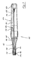
- einen Längsschnitt durch ein Ausführungsbeispiel der Erfindung, bei welchem der Bildwandler beim objektivseitigen Ende der Kamera vorgesehen ist;
- Fig. 8
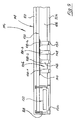
- eine ähnliche Ansicht wie
Figur 7 , wobei jedoch das Kopfteil abgenommen ist; - Fig.9
- eine vergrößerte Ansicht des freien Endabschnittes des Griffteiles in vergrößertem Maßstabe;
- Fig. 10
- eine ähnliche Ansicht wie
Figur 9 , wobei jedoch ein Winkel-Kopfteil auf das Ende des Griffteiles aufgesetzt ist; - Fig. 11
- eine ähnliche Ansicht wie
Figur 10 , wobei jedoch anstelle des Winkel-Kopfteiles ein Geradsicht-Kopfteil auf das Griffteil aufgesetzt ist; und - Fig. 12
- ein abgewandeltes Geradsicht-Kopfteil in axialer Schnittansicht.
- Die
Fig.1 zeigt eine Handstück-Kamera, die beispielsweise im Mundbereich oder zur Betrachtung der Haut verwendbar ist. - Die Kamera weist ein Gehäuse 10 mit einem Kopfteil 12 und eieinem Griffteil 14 auf. In dem Kopfteil 12 ist ein Eintrittsfenster 16 angeordnet. In dem Kopfteil 12 ist eine ringförmige Lichtquelle 18 angeordnet, die Weißlicht erzeugt. Die Lichtquelle 18 umfasst mehrere um das Eintrittsfenster 16 verteilt angeordnete Leuchtdioden.
- Eine erste Linse 20a ist beabstandet hinter dem Eintrittsfenster 16 im Kopfteil 12 angeordnet. Fest mit dem Kopfteil 12 verbunden ist ein Umlenkprisma 20b angeordnet. Zur Vermeidung von Beschädigungen ist auf dem Prisma 20b eine Schutzkappe 22 angeordnet.
- Im Griffteil 14 sind weitere Linsen 20c, 20d, 20e und eine Blende 24 angeordnet, und hinter diesen Komponenten befindet sich ein Bildwandler 26.
- Zur Einstellung der Bildschärfe ist eine schematisch bei 27 gezeigter Antrieb zum Verschieben des Bildwandlers 26 in Richtung der optischen Längsachse 28 des Griffteiles 14 vorgesehen.
- Der Bildwandler 26 ist mit einer Kameraelektronik 30 verbunden, die eine Einstellung von Kamerakomponenten optischer und elektronischer Art als auch eine Darstellung und geeignete Bearbeitung eines aufgenommenen Bildes ermöglicht.
- An dem Kopfteil 12 ist ein Transponder 32 angeordnet, der Informationen über den Aufbau des Kopfteiles 12 enthält. Sobald das Kopfteil 12 wie gezeichnet mit einem Griffteil 14 gepaart ist, liest ein im Griffteil 14 angeordnetes Lesegerät 34 diese Informationen aus und übermittelt diese an die Kameraelektronik 30 weiter. Aufgrund der übermittelten Informationen über den Aufbau des Kopfteiles 12 nimmt die Kameraelektronik 30 automatisch verschiedene Betriebseinstellung vor, beispielsweise eine Einstellung des Weißabgleichs, eine Einstellung der Spannung für die Beleuchtungseinheit 18, eine Einstellung der Blende 24, eine Einstellung einer Bildsignal-Verstärkung und/oder einer Fokussierung.
- Das Kopfteil 12 weist auf der dem Griffteil 14 zugewandten Seite einen Rastwulst 36 auf, der in eine im Griffteil 14 vorgesehene Nut 38 unter Vorspannung eingeschnappt ist. Damit kann das Kopfteil 12 ohne Werkzeug unter leichter Kraftaufwendung vom Griffteil 14 abgenommen und durch ein anderes Kopfteil 12 ersetzt werden.
- Bei der Untersuchung eines Prüfobjektes, beispielsweise eines Zahnes, wird das Eintrittsfenster 16 auf die zu untersuchende Stelle gerichtet. Von der Lichtquelle 18 abgestrahltes Licht trifft auf das Prüfobjekt auf. Das von der Lichtquelle abgestrahlte Weißlicht wird von dem Prüfkörper als Beobachtungslicht reflektiert. Das Beobachtunglicht tritt über das Eintrittsfenster 16 in die Kamera ein und wird durch das Umlenkprisma 20b über die Linsen 20c, 20d, 20e und die Blende 24 auf den Bildwandler 26 gerichtet.
- Die
Fig. 2 zeigt ein weiteres Kopfteil 12, das gegen das Kopfteil 12 inFig. 1 austauschbar ist. Diese Variante des Kopfteiles 12 und auch die der weiteren Figuren sind der besseren Lesbarkeit halber mit dem gleichen Bezugszeichen bezeichnet, obgleich sich deren Aufbau unterscheidet. - Die gesamte aufwendige Optik und Elektronik des Griffteiles 14 der
Fig. 1 ist mit dem Kopfteil 12 derFig. 2 für weitere Untersuchungen nutzbar. Im Gegensatz zu dem Kopfteil 12 inFig. 1 umfasst die Lichtquelle 18 nun UV-Leuchtdioden. Das UV-Licht regt etwa vom Prüfkörper getragene Bakterien optisch an, so dass diese als Beobachtungslicht Fluoreszenzlicht anderer Farbe abstrahlen. Anhand von Fluoreszenzlicht, das auf von Bakterien zurückgeht, sind gesunde und kranke Gewebebereiche unterscheidbar. - Das Eintrittsfenster 16 ist als Tiefpass-Kantenfilter ausgeführt, das das anregende UV-Licht vollständig absorbiert, so dass nur das Fluoreszenzlicht auf den Bildwandler 26 fällt.
-
Fig. 3 zeigt eine weiteres Geradsicht-Kopfteil 12, das mit dem Griffteil 14 ausFig.1 kombinierbar ist. Dieses Kopfteil 12 leitet das Beobachtungslicht ohne Umlenkung entlang der optischen Längsachse 28 in Richtung Bildwandler 26. Die Lichtquelle 18 umfasst besonders starke, beispielsweise für extraorale Aufnahmen geeignete Weißlichtleuchtdioden. - Die drei gezeigten Kopfteile 12 der
Figuren 1 bis 3 stellen lediglich beispielhafte Ausführungsbeispiele dar, die mit dem Griffteil 14 ausFig. 1 kombinierbar sind. Beispielsweise sind Kopfteile 12 mit weiteren Linsen für Weitwinkel- oder Makroaufnahmen sowie mit weiteren oder anderen Filtern darstellbar. Weiter können an den Kopfteilen 12 je nach Einsatzzweck unterschiedliche Lichtquellen 18 angeordnet sein, z.B. Infrarot- bzw. Laserlichtquellen, Lichtquellen unterschiedlicher oder einstellbarer Intensität oder gepulste Lichtquellen. - Ein weiteres Nutzungsfeld der Teilung der Kamera in Kopfteil und Griffteil erschließt sich durch Adapter, die einen Anschluss an ein Mikroskop oder ein Endoskop ermöglichen.
- Die
Fig.4 zeigt eine weitere Ausführungsform einer Kamera mit einem Kopfteil 12 und einem Griffteil 14. Die Anordnung der optischen Elemente 20b, 20d, 20e und 24 entspricht der inFig. 1 beschriebenen Ausführung. - Das Kopfteil 12 umfasst eine Weißlichtdioden-Lichtquelle 18 und ein Eintrittsfenster 16.
- Im Griffteil 14 ist ein in Richtung der optischen Längsachse 28 verschiebbarer Dauermagnet 40a angeordnet, wobei der Südpol in Richtung Kopfteil 12 zeigt. Der quaderförmige Magnet 40a ist über eine Stange 42 mit einer an der Gehäuseinnenseite abgestützten Feder 44 verbunden. Mit der Stange 42 gekoppelt ist eine Keil 46a, dessen Keilfläche in Abwandlung auch als Steuerkurve ausgebildet sein kann.
- Auf der Oberfläche des Keiles 46a läuft eine durch Federkraft in der Zeichnung nach oben vorgespannte Rolle 46b, die einen nicht gezeichneten Verstellmechanismus der Blende 24 betätigt. Die Feder 44 hält den Magneten 40a in einer definierten Stellung, wodurch über das Keilelement 46a und die Rolle 46b ein definierter Blendenwert eingestellt ist.
- Zwei Reedschalter 48, 50 sind beabstandet zum Magneten 40a angeordnet, so dass diese normalerweise geöffnet sind. Die Reedschalter 48, 50 sind über nicht dargestellte Kabel mit der Kameraelektronik 30 verbunden.
- Die
Fig. 5 zeigt das Griffteil 14 ausFig. 4 in Kombination mit einem anderen Kopfteil 12. - Im Kopfteil 12 der
Fig. 5 ist für Aufnahmen außerhalb der Mundhöhle eine stark leuchtende Leuchtdioden umfassende Lichtquelle 18 angeordnet. Im Kopfteil 12 ist im Gegensatz zu der Ausführung inFig. 1 ein Magnet 40b angeordnet, dessen Südpol in Richtung Griffteil 14 gerichtet ist. Aufgrund der sich abstoßenden Pole des Magneten 40b und des Magneten 40a verschiebt sich letzterer beim Aufsetzten des Kopfteiles 12 auf das Griffteil 14 gegen die Kraft der Feder 44 in Richtung der Längsachse 28 vom Kopfteil 12 weg. Gleichzeitig verschiebt sich auch das Keilelement 46a in gleicher Richtung, womit die durch Federkraft vorgespannte Rolle 46b auf der Keilfläche nach oben läuft und damit die Blende 24 weiter öffnet. - Durch Annäherung des Magnete 40a verringert sich der Abstand zum Reedschalter 50, so dass dieser schließt. Die Kameraelektronik 30 erkennt den geschlossenen Kontakt 40a und stellt den Weißabgleich, Verstärkung etc. auf auf das Kopfteil 12 der
Fig. 5 abgestimmte Werte ein. - In
Fig. 6 ist wiederum das Griffteil 14 ausFig. 5 gezeigt, das zusätzlich zum Aufbau des Kopfteils 12 ausFig. 4 eine zum Eintrittsfenster 16 beabstandete optische Linse 20a aufweist, die beispielsweise für Makroaufnahmen geeignet ist. - Im Kopfteil 12 ist ferner ein Dauermagnet 40b angeordnet, dessen Nordpol dem Griffteil 14 zugewandt ist. Die Magnete 40b und 40a ziehen sich gegenseitig an, wodurch sich der Magnet 40a in Richtung Kopfteil 12 verlagert. Mit dem Magneten 40a verlagert sich wiederum der Keil 46a, die Rolle 46b rollt auf der Keilfläche in der Zeichnung nach unten und schließt die Blende 24 weiter.
- Aufgrund der Vergrößerung des Abstands des Magneten 40a zum Reedkontakt 50 öffnet sich dieser. Der Abstand des Magneten 40a zum Reedkontakt 48 verringert sich, so dass dieser schließt. Die Signale der Reedkontakte 48, 50 wertet die Kameraelektronik 30 wie vorab beschrieben aus und nimmt entsprechende Einstellungen vor.
- In einem alternativen nicht gezeigten Ausführungsbeispiel übernimmt die Kameraelektronik 30 aufgrund der Auswertung der Stellung der Reedkontakte 48, 50 die Verstellung der Blende 24 durch Ansteuerung eines elektrischen Antriebes.
- Das in den
Figuren 7 ff. gezeigte Kamera-Handstück umfasst ein Gehäuse 110, zu dem ein lösbares Kopfteil 112 sowie ein Griffteil 114 gehören. - Das Griffteil 114 hat einen größeren Durchmesser aufweisenden Basisabschnitt 116 sowie einen von diesem getragenen schlanken langen Säulenabschnitt 118. Der Säulenabschnitt 118 ist auf einem schalenförmigen Befestigungsabschnitt 120 angeordnet und hat eine in Figur oben liegende erste achsparallele Hauptwand 122 sowie eine in
Figur 7 unten liegende parallele Hauptwand 124. Deren Längskanten sind durch Seitenwände 126 miteinander verbunden, von denen nur eine inFigur 7 erkennbar ist. - Das in
Figur 7 links liegende vordere Ende des Säulenabschnittes 118 ist durch eine Stirnwand 128 verschlossen. - Im Inneren des Säulenabschnittes 118 findet der Hauptwand 122 benachbart eine Hauptplatine 130 Aufnahme. Diese trägt bei ihrem freien Ende einen Kamera-Chip 132. Dessen Eingangsfenster ist durch ein Fenster 134 frei zugänglich, welches beim freien Ende der Hauptwand 124 vorgesehen ist.
- Zusätzlich trägt die Hauptplatine 130 zwei Kontaktgruppen 136 mit Kontakten 138-1, 138-2, 138-3, 138-4, die paarweise senkrecht zur Zeichenebene der Figuren fluchtend hintereinanderliegen. Jeder der Kontakte 138 hat einen flanschförmigen Basisabschnitt 144, über den er mit einer Leiterbahn der Hauptplatine 130 mechanisch und elektrisch verbunden ist. Der Basisabschnitt 144 trägt jeweils einen Zapfenabschnitt 146, und die Zapfenabschnitte 146 haben jeweils einen kugelförmigen Endabschnitt 148. Die Enden der Zapfenabschnitte 146 und Endabschnitte 148 stehen in Öffnungen 150, die in der unteren Hauptwand 124 ausgebildet sind, derart, dass ein Teil der Endabschnitte 148 nach unten übersteht.
- Die Hauptplatine 130 trägt ferner etwa bei ihrer Mitte einen Motor 152, der einen Unwuchtkörper 154 antreibt. Der Motor 152 wird erregt, wenn an einem am Gehäuse 110 angebrachten Taster eine Betätigung (z.B. für das Aufzeichnen eines Bildes) erfolgt, wodurch eine taktile Rückmeldung über den korrekten Empfang des Befehles erstellt wird.
- Am in den Figuren rechts gelegenen Ende ist die Hauptplatine 130 über Leiter 156 mit einem Steckverbinderteil 158 verbunden, über welches ein Anschluss der Handstück-Kamera an eine externe Betriebs- und Auswerteeinheit folgt.
- Das Kopfteil 112 hat grob gesprochen solche Form, dass es den Säulenabschnitt 118 unter geringem Spiel umgibt. Es hat eine obere Hauptwand 116, eine untere Hauptwand 162, Seitenwände 166, von denen wieder nur eine in der Zeichnung sichtbar ist, sowie eine Endwand 168. Diese Wände bilden zusammen, ähnlich wie die Wände des Säulenabschnittes 118 eine quaderförmige Struktur mit großzügig abgerundeten Längskanten und Querkanten.
- Das Kopfteil 112 trägt in seinem Inneren eine Nebenplatine 170, die über zwei später noch genauer zu beschreibende Gegenkontaktgruppen 172 mit der Kontaktgruppe 136 zusammenarbeitet.
- Die Gegenkontaktgruppen 172 umfassen Gegenkontakte 174-1, 174-2, 174-3 und 174-2, die paarweise fluchtend hintereinander liegen und deren Abstand dem Abstand der Kontakte 138 entspricht.
- Bei ihrem freien, in der Zeichnung links gelegenen Ende ist die Nebenplatine 170 mit einer Öffnung 175 versehen, in welche ein Objektiv 176 fest eingesetzt ist.
- Eine Objektivfassung ist außen abgestuft und nimmt dort einen hülsenförmigen Nabenabschnitt 178 einer kreisscheibenförmigen Fensterplatte 180 auf, die aus im Sichtbaren und ggf. im UV transparentem Kunststoffmaterial hergestellt ist. Die Fensterplatte 180 ist nicht eben, sondern stellt in verschiedenen Teilbereichen glatt Fortsetzungen der Außenfläche des Gehäuses 110 dar, so dass die Außenfläche des Gehäuses im Bereich der Fensterplatte 180 insgesamt glatt durchgehend ist.
- Die Unterseite der Nebenplatine 170 trägt über der Fensterplatte 118 liegend einen Kranz von Leuchtdioden 182, die in Umfangsrichtung gleich verteilt sind und nach unten Weißlicht oder blaues oder ultraviolettes Licht abstrahlen. Es können auch zwei verschachtelte Sätze in Umfangsrichtung verteilter LEDs vorgesehen sein, von denen der eine Satz Weißlicht, der andere blaues Licht oder ultraviolettes Licht bereitstellt.
- Auf der Oberseite der Nebenplatine 170 ist ein IC 184 erkennbar, der einen RFID oder einen anderen Transponder enthält, welcher Daten betreffend den Typ des Kopfteiles 112 und ggfs. noch weiterer Einzelheiten über das Kopfteil 112 enthält, die für das Auslesen des Kamera-Chips 132 und/oder für die Auswertung oder Bearbeitung des von diesem Chip aufgenommenen Bildes nützlich sind. Der IC 184 arbeitet mit einem entsprechenden Empfängerchip 186 zusammen, welcher auf der Hauptplatine 130 angeordnet ist, wie aus
Figur 10 ersichtlich. - Die Kontaktfedern 172 sind aus einem streifenförmigen Blattfedermaterial hergestellt, welches gute elektrische Leitung aufweist. Die Kontaktfedern 170 haben grob gesprochen die Form eines Rechteckes, welches im oberen rechten Abschnitt aufgebrochen ist und dort zwei Federarme 188, 190 aufweist. Die Federarme 188, 190 sind an ihren freien Enden kreisbogenförmig passend zur Krümmung der Endabschnitte 148 gestaltet.
- Die untere Seite des Rechteckes weit eine trapezförmige Eindrückung 192 auf, und der rechts der letzteren gelegene Bereich der unteren Rechteckseite ist konvex gewölbt, wie bei 194 gezeigt. Der Federarm 190 ist im unbelasteten Zustand ebenfalls konvex kreisbogenförmig gekrümmt, wie aus der Ausschnittvergrößerung von
Figur 10 ersichtlich. - Die Kontakte 138 sowie die hierzu parallel hinter der Zeichenebene angeordneten Kontakte bilden die gehäusefeste Kontaktgruppe 136, während die Kontaktfedern 174 die bewegliche Gegenkontaktgruppe 172 bilden. Die Kontakte können sowohl zum Austausch von Information zwischen elektronischen Baueilen auf der Nebenplatine 170 und elektronischen Bauteile auf der Hauptplatine 130 dienen, als auch zur Ansteuerung von Aktoren oder anderen elektrischen Verbrauchern dienen, die auf der Nebenplatine angeordnet sind, als auch zur Spannungsversorgung auf der Nebenplatine angeordneter Lasten dienen.
- Dabei sind die Kontakte 138-1, die beim Aufstecken des Kopfteiles 112 als letzte geschlossen werden, dazu bestimmt, die zum Betreiben der von der Nebenplatine 170 getragenen Bauteile notwendige Speisespannung zu übertragen. Das Aufstecken des Kopfteiles 112 erfolgt somit spannungsfrei, bis die Kontakte 138-1 mit den zugeordneten Gegenkontakten 174-1 in Eingriff kommen.
- Beim Ausführungsbeispiel nach
Figur 11 ist auf das Griffteil 114 ein Geradsicht-Kopfteil 112 aufgesetzt. Bei ihm fällt die Achse der Linsenanordnung 176 mit der Achse des Griffteiles 114 zusammen. - Das Zuführen des von der Beobachtungsstelle zurückgeführten Lichtes zum Kamera-Chip 132 erfolgt durch ein abgewinkeltes Prisma 196 aus transparentem optischen Material, welches bei den beiden Enden seiner Arme unter 45° angestellte Spiegelflächen 198, 200 aufweist und an der Stoßstelle der beiden Arme eine ebenfalls unter 45° angestellte Spiegelfläche 202 trägt. Diese Spiegel können dadurch realisiert sein, dass eine Verspiegelung auf entsprechend angestellten und geschliffenen Endflächen des Prismas 196 aufgebracht wird, z. B. durch Aufdampfen.
- Ein weiterer Unterschied des Kopfteiles 112 nach
Figur 11 zu demjenigen nachFigur 10 liegt darin, dass um das Objektiv herum ein Kranz von normalen Leuchtdioden 182 vorgesehen ist, die Weißlichtdioden, UV-Dioden oder Blaulicht-Dioden oder eine Mischung dieser Diodentypen sein können. - Im Übrigen sind in
Figur 11 dasselbe Bezugszeichen verwendet wie inFigur 10 . Die entsprechenden Komponenten brauchen nicht nochmals detalliert beschrieben zu werden. - In
Figur 12 ist ein nochmals abgewandeltes Kopfteil 112 dargestellt, welches ebenfalls ein Geradsicht-Kopfteil ist. Hier befindet sich die Achse der Linsenanordnung 176 etwas unterhalb der Achse des Griffteiles 114, was es erlaubt, das vom Untersuchtungsort zurückgeworfene Licht unter Verwendung eines einfachen Dreikant-Prismas 196 auf den Kamera-Chip 132 zu führen.
Claims (15)
- Handstück-Kamera, die ein Gehäuse (10; 110), vom Gehäuse (10; 110) getragene optische Elemente (20a, 20b, 20c, 20d, 24; 176; 196) und einen im Gehäuse (10; 110) angeordnetten Bildwandler (26; 132) umfasst, wobei das Gehäuse (10; 110) ein Griffteil (14; 114) und ein lösbar mit diesem verbundenes Kopfteil (12; 112) umfasst,
dadurch gekennzeichnet, dassa) das Griffteil (14; 114) einen Basisabschnitt (116) sowie einen schlankeren Säulenabschnitt (118) umfasst, in dessen Innerem eine Hauptplatine (130) aufgenommen ist, die bei ihrem freien Ende den Bildwandler (26; 132) trägt,b) das lösbare Kopfteil (112) eine solche Form hat, dass es den Säulenabschnitt (118) umgibt, und dassc) das Kopfteil (12; 112) mit dem Basisabschnitt (116) des Griffteils (14; 114) über eine Verrastung (36) verbunden ist. - Handstück-Kamera nach Anspruch 1 dadurch gekennzeichnet, dass eine Beleuchtungseinrichtung (18) von dem Kopfteil (12) getragen ist, die UV-Licht und/oder Weißlicht und/oder IR-Licht abstrahlt.
- Handstück-Kamera nach Anspruch 1 oder 2 dadurch gekennzeichnet, dass mindestens eines (20a; 176; 196) der optischen Elemente (20a, 20b, 20c, 20d, 24; 176; 196) in dem Kopfteil (12; 112) angeordnet ist.
- Handstück-Kamera nach Anspruch 3, dadurch gekennzeichnet, dass das mindestens eine optische Element ein Filter umfasst.
- Handstück-Kamera nach Anspruch 3, dadurch gekennzeichnet, dass das mindestens eine optische Element eine Umlenkeinrichtung (20b) ist.
- Handstück-Kamera nach einem der Ansprüche 1 bis 5, dadurch gekennzeichnet, dass zwischen dem Kopfteil (12) und dem Griffteil (14) eine thermisch leitende Verbindung vorgesehen ist.
- Handstück-Kamera nach Anspruch 9, dadurch gekennzeichnet, dass eine elektrische Kontaktanordnung zwischen dem Kopfteil (12; 112) und dem Griffteil (14; 114) vorgesehen ist.
- Handstück-Kamera nach Anspruch 7, dadurch gekennzeichnet, dass die elektrische Kontaktanordnung (136, 172) mindestens einen Satz, vorzugsweise zwei oder mehr Sätze in Steckrichtung des Kopfteiles (112) hintereinander liegender Kontakte (138, 174) aufweist.
- Handstück-Kamera nach Anspruch 8, dadurch gekennzeichnet, dass zur Energieversorgung des Kopfteiles (112) dienende Kontakte (138-1, 174-1) die letzten beim Aufstecken des Kopfteiles (112) geschlossenen Kontakte sind.
- Handstück-Kamera nach Anspruch 8 oder 9, dadurch gekennzeichnet, dass die Kontaktanordnung (136, 172) Kontakte (138) mit abgerundeten Endabschnitten (148) und mit diesen zusammenarbeitende Gegenkontakte (174) aufweist, die blattfederähnlich ausgebildet sind.
- Handstück-Kamera nach Anspruch 10, dadurch gekennzeichnet, dass die Gegenkontakte (174) jeweils zwei Blattfederarme (188, 190) aufweisen, die von zwei Seiten her einen Kontakt (136 bis 142) zwischen sich aufnehmen.
- Kamera-Handstück nach Anspruch 11, dadurch gekennzeichnet, dass die freien Enden der Blattfederarme (188, 190) freie Endkanten haben, die kreisbogenförmig gestaltet sind.
- Handstück-Kamera nach einem der Ansprüche 1 bis 12, dadurch gekennzeichnet, dass Einstellmittel (40a, 40b, 48, 50; 34, 32) vorgesehen sind, die in Abhängigkeit von der Ausbildung des am Griffteil (14) angeordneten Kopfteils (12) auf ein optisches Element (20a, 20b, 20c, 20d, 24) und/oder ein elektrisches Element (30) wirken.
- Handstück-Kamera nach Anspruch 13, dadurch gekennzeichnet, dass die Einstellmittel einen Transponder (32) und ein Transponder-Lesegerät (34) umfassen.
- Handstück-Kamera nach einem der Ansprüche 13 bis 14, dadurch gekennzeichnet, dass die Einstellmittel mit einer mit dem Bildwandler (26) verbundenen Kameraelektronik (30) zusammenwirken, die in Abhängigkeit von der Ausbildung des Kopfteils (12) zu diesem gehörige Einstellungen zur Bildaufnahme und Auswertung vornimmt.
Applications Claiming Priority (2)
| Application Number | Priority Date | Filing Date | Title |
|---|---|---|---|
| DE102009041151.8A DE102009041151B4 (de) | 2009-09-14 | 2009-09-14 | Handstück-Kamera |
| PCT/EP2010/005237 WO2011029530A1 (de) | 2009-09-14 | 2010-08-26 | Handstück-kamera |
Publications (2)
| Publication Number | Publication Date |
|---|---|
| EP2477528A1 EP2477528A1 (de) | 2012-07-25 |
| EP2477528B1 true EP2477528B1 (de) | 2016-06-29 |
Family
ID=42989492
Family Applications (1)
| Application Number | Title | Priority Date | Filing Date |
|---|---|---|---|
| EP10750056.3A Active EP2477528B1 (de) | 2009-09-14 | 2010-08-26 | Handstück-kamera |
Country Status (7)
| Country | Link |
|---|---|
| US (1) | US20120281135A1 (de) |
| EP (1) | EP2477528B1 (de) |
| AU (1) | AU2010294581A1 (de) |
| DE (1) | DE102009041151B4 (de) |
| EA (1) | EA035239B1 (de) |
| ES (1) | ES2592382T3 (de) |
| WO (1) | WO2011029530A1 (de) |
Families Citing this family (7)
| Publication number | Priority date | Publication date | Assignee | Title |
|---|---|---|---|---|
| DE102004024494B4 (de) * | 2004-05-16 | 2019-10-17 | Dürr Dental SE | Medizinische Kamera |
| ITBO20120451A1 (it) * | 2012-08-23 | 2014-02-24 | Cefla Coop | Telecamera per uso medicale con selezione di diverse modalità di funzionamento |
| US20140142383A1 (en) * | 2012-11-22 | 2014-05-22 | Gyrus Acmi, Inc. (D.B.A. Olympus Surgical Technologies America) | Endoscope Camera Head Memory |
| USD780182S1 (en) * | 2013-03-11 | 2017-02-28 | D4D Technologies, Llc | Handheld scanner |
| DE102015111757A1 (de) * | 2015-03-09 | 2016-09-15 | Sycotec Gmbh & Co. Kg | Dentales oder chirurgisches Handstück |
| US11497389B2 (en) | 2018-10-03 | 2022-11-15 | Karl Storz Imaging, Inc. | Attachment system for conditioning light between endoscope and camera |
| CN117202871A (zh) | 2021-04-28 | 2023-12-08 | 阿伊里斯株式会社 | 拍摄装置以及拍摄系统 |
Citations (2)
| Publication number | Priority date | Publication date | Assignee | Title |
|---|---|---|---|---|
| US20050003323A1 (en) * | 2003-01-14 | 2005-01-06 | J. Morita Manufacturing Corporation | Diagnostic imaging apparatus |
| DE102007013355A1 (de) * | 2007-03-16 | 2008-09-18 | Dürr Dental GmbH & Co. KG | Diagnosekamera sowie Aufsatz zur Realisierung einer solchen |
Family Cites Families (45)
| Publication number | Priority date | Publication date | Assignee | Title |
|---|---|---|---|---|
| JPS61293439A (ja) * | 1985-06-21 | 1986-12-24 | オリンパス光学工業株式会社 | 超音波内視鏡 |
| US4941457A (en) * | 1989-08-17 | 1990-07-17 | Olympus Optical Co., Ltd. | Endoscope using an optical guide twisted on the tip side to have the visual field direction and curvature axis coincide with each other |
| US6025873A (en) * | 1994-04-07 | 2000-02-15 | Olympus Optical Co., Ltd. | Endoscope system provided with low-pass filter for moire removal |
| US6184923B1 (en) * | 1994-11-25 | 2001-02-06 | Olympus Optical Co., Ltd. | Endoscope with an interchangeable distal end optical adapter |
| US6069651A (en) * | 1995-04-20 | 2000-05-30 | Olympus Optical Co., Ltd. | Imaging apparatus for endoscopes |
| US6095970A (en) * | 1997-02-19 | 2000-08-01 | Asahi Kogaku Kogyo Kabushiki Kaisha | Endoscope |
| JP3665442B2 (ja) * | 1997-02-19 | 2005-06-29 | ペンタックス株式会社 | 電子内視鏡 |
| JPH10258034A (ja) * | 1997-03-19 | 1998-09-29 | Olympus Optical Co Ltd | 内視鏡用撮像装置 |
| JP3401215B2 (ja) * | 1998-12-15 | 2003-04-28 | オリンパス光学工業株式会社 | 内視鏡用光学アダプタ及び内視鏡装置 |
| AU3245500A (en) * | 1999-02-25 | 2000-09-14 | Minimed, Inc. | Test plug and cable for a glucose monitor |
| JP2001046321A (ja) * | 1999-08-09 | 2001-02-20 | Asahi Optical Co Ltd | 内視鏡装置 |
| US6796939B1 (en) * | 1999-08-26 | 2004-09-28 | Olympus Corporation | Electronic endoscope |
| JP2001125009A (ja) * | 1999-10-28 | 2001-05-11 | Asahi Optical Co Ltd | 内視鏡装置 |
| US7057639B2 (en) | 2001-02-28 | 2006-06-06 | Eastman Kodak Company | Intra-oral camera with integral display |
| JP4716595B2 (ja) * | 2001-04-04 | 2011-07-06 | オリンパス株式会社 | 内視鏡装置及び内視鏡用光学アダプタの組立て方法 |
| DE10121450A1 (de) * | 2001-04-27 | 2002-11-21 | Storz Endoskop Gmbh Schaffhaus | Optisches Instrument, insbesondere Endoskop, mit Wechselkopf |
| JP2002359761A (ja) * | 2001-05-31 | 2002-12-13 | Asahi Optical Co Ltd | デジタルカメラ用クレードル |
| WO2003038410A1 (en) * | 2001-10-31 | 2003-05-08 | Olympus Corporation | Optical scanning type observation device |
| US9510740B2 (en) * | 2002-03-12 | 2016-12-06 | Karl Storz Endovision, Inc. | Auto recognition of a shaver blade for medical use |
| JP3938722B2 (ja) * | 2002-07-03 | 2007-06-27 | オリンパス株式会社 | 内視鏡装置 |
| WO2004059613A1 (en) * | 2002-12-20 | 2004-07-15 | Itac Systems, Inc. | Cursor control device |
| JP4320184B2 (ja) * | 2003-02-10 | 2009-08-26 | Hoya株式会社 | 対物レンズユニット、該対物レンズユニットの組立方法 |
| JP4564239B2 (ja) | 2003-04-11 | 2010-10-20 | オリンパス株式会社 | 内視鏡装置 |
| JP4418202B2 (ja) * | 2003-10-06 | 2010-02-17 | オリンパス株式会社 | 内視鏡 |
| US8435173B2 (en) * | 2003-10-06 | 2013-05-07 | Olympus Corporation | Endoscope |
| DE10359337B4 (de) * | 2003-12-16 | 2007-10-31 | Blazejewski Medi-Tech Gmbh | Endoskop |
| JP4524099B2 (ja) * | 2003-12-19 | 2010-08-11 | オリンパス株式会社 | 内視鏡装置 |
| DE102004024494B4 (de) * | 2004-05-16 | 2019-10-17 | Dürr Dental SE | Medizinische Kamera |
| JP4603291B2 (ja) * | 2004-05-21 | 2010-12-22 | オリンパス株式会社 | 内視鏡装置 |
| IL162251A0 (en) * | 2004-05-31 | 2005-11-20 | Medigus Ltd | A reusable laparoscopic or endoscopic camera head |
| JPWO2006001377A1 (ja) * | 2004-06-28 | 2008-04-17 | オリンパス株式会社 | 内視鏡装置 |
| JP4934299B2 (ja) * | 2005-08-10 | 2012-05-16 | オリンパス株式会社 | 内視鏡装置 |
| US20070156021A1 (en) * | 2005-09-14 | 2007-07-05 | Bradford Morse | Remote imaging apparatus having an adaptive lens |
| JP4744288B2 (ja) * | 2005-12-21 | 2011-08-10 | オリンパスメディカルシステムズ株式会社 | 内視鏡装置 |
| JP4947975B2 (ja) * | 2005-12-28 | 2012-06-06 | オリンパス株式会社 | 内視鏡装置および内視鏡用照明装置 |
| JP4986646B2 (ja) * | 2007-02-05 | 2012-07-25 | オリンパス株式会社 | 内視鏡装置 |
| KR100860308B1 (ko) * | 2007-06-05 | 2008-09-25 | 삼성전기주식회사 | 카메라 모듈 패키지 및 그 제조방법 |
| EP2039931B1 (de) * | 2007-09-18 | 2012-06-06 | Olympus Medical Systems Corp. | Aktuator und Bildaufnahmevorrichtung |
| US8641606B2 (en) * | 2008-02-05 | 2014-02-04 | Masaki ICHIHASHI | Endoscope apparatus |
| US8900134B2 (en) | 2008-02-12 | 2014-12-02 | Olympus Corporation | Endoscope apparatus and method of controlling endoscope apparatus |
| US7868721B2 (en) * | 2008-04-04 | 2011-01-11 | Cedar Ridge Research, Llc | Field emission system and method |
| DE102008018636B4 (de) * | 2008-04-11 | 2011-01-05 | Storz Endoskop Produktions Gmbh | Vorrichtung und Verfahren zur endoskopischen 3D-Datenerfassung |
| CN101592772A (zh) * | 2008-05-27 | 2009-12-02 | 鸿富锦精密工业(深圳)有限公司 | 镜头装置、用于收容该镜头装置的电子装置及摄像设备 |
| US7855478B2 (en) * | 2008-10-01 | 2010-12-21 | Wandzilak Brian | Machine for generating reciprocal motion and related method |
| US8063367B2 (en) * | 2009-04-23 | 2011-11-22 | Fluke Corporation | Lens position sensor for infrared cameras |
-
2009
- 2009-09-14 DE DE102009041151.8A patent/DE102009041151B4/de not_active Expired - Fee Related
-
2010
- 2010-08-26 WO PCT/EP2010/005237 patent/WO2011029530A1/de not_active Ceased
- 2010-08-26 EP EP10750056.3A patent/EP2477528B1/de active Active
- 2010-08-26 AU AU2010294581A patent/AU2010294581A1/en not_active Abandoned
- 2010-08-26 EA EA201200482A patent/EA035239B1/ru not_active IP Right Cessation
- 2010-08-26 US US13/496,111 patent/US20120281135A1/en not_active Abandoned
- 2010-08-26 ES ES10750056.3T patent/ES2592382T3/es active Active
Patent Citations (2)
| Publication number | Priority date | Publication date | Assignee | Title |
|---|---|---|---|---|
| US20050003323A1 (en) * | 2003-01-14 | 2005-01-06 | J. Morita Manufacturing Corporation | Diagnostic imaging apparatus |
| DE102007013355A1 (de) * | 2007-03-16 | 2008-09-18 | Dürr Dental GmbH & Co. KG | Diagnosekamera sowie Aufsatz zur Realisierung einer solchen |
Also Published As
| Publication number | Publication date |
|---|---|
| EP2477528A1 (de) | 2012-07-25 |
| US20120281135A1 (en) | 2012-11-08 |
| DE102009041151A1 (de) | 2011-03-24 |
| ES2592382T3 (es) | 2016-11-29 |
| WO2011029530A1 (de) | 2011-03-17 |
| EA201200482A1 (ru) | 2012-10-30 |
| EA035239B1 (ru) | 2020-05-20 |
| AU2010294581A1 (en) | 2012-05-10 |
| DE102009041151B4 (de) | 2019-06-13 |
Similar Documents
| Publication | Publication Date | Title |
|---|---|---|
| DE102009041151B4 (de) | Handstück-Kamera | |
| DE69326409T2 (de) | Endoskop mit Scharfeinstellung | |
| EP1074214B1 (de) | Gerät zur Augenuntersuchung mit einer Scheimpflugkamera und einem Spaltprojektor | |
| EP3073307B1 (de) | Vorrichtung zum aufnehmen eines bildes eines objektfelds an einem menschlichen oder tierischen körper | |
| DE102008018636B4 (de) | Vorrichtung und Verfahren zur endoskopischen 3D-Datenerfassung | |
| DE102004001856B4 (de) | Bilderstellungsgerät für Diagnosezwecke | |
| DE69727577T2 (de) | Tragbare endoskopische hand-kamera | |
| EP2850996B1 (de) | Vorrichtung zum Aufnehmen eines Bildes eines Objektfelds an einem menschlichen oder tierischen Körper | |
| WO2003021308A2 (de) | Steckverbinder für ein kompositkabel | |
| DE102009017819A1 (de) | Dentale oder medizinische Kamera | |
| EP1522253A1 (de) | Elektronisches Endoskop | |
| EP1595495B1 (de) | Zahnärztliche Vorrichtung zum Untersuchen der optischen Eigenschaften von Zahngewebe | |
| DE102008049922A1 (de) | Endoskop | |
| EP1058860B1 (de) | Kamera und insbesondere modulare dentalkamera | |
| WO2020178723A1 (de) | Endoskop mit lichtabstrahleinrichtung und bildaufnahmeeinrichtung am distalen endabschnitt | |
| DE102022131502A1 (de) | Filterschaltvorrichtung für einen endoskopischen Kamerakopf, Kamerakopf und Nachrüstsatz zum Nachrüsten eines Kamerakopfs und/oder eines Endoskops | |
| DE102023125039B3 (de) | Endoskopvorrichtung und Endoskop mit einer Endoskopvorrichtung | |
| EP1322988A1 (de) | Dermatologie-handlupe | |
| DE10049835C2 (de) | Miniaturisierte Kamera mit einer in einem stab- oder rohrförmigen Gehäuse angeordneten photosenitiven CCD-Matrix und einer integrierten Beleuchtungseinrichtung | |
| DE10020716B4 (de) | Dermatologie-Bildaufnahmesystem | |
| WO2001067956A9 (de) | Dermatologie-bildaufnahmesystem | |
| DE102023103175A1 (de) | Endoskop, Basismodul und Handhabungsmodul für ein Endoskop, steriles Single-Use Produkt, System und ein Verfahren zur Bereitstellung eines Endoskops | |
| DE10245142A1 (de) | Miniaturisierte Kamera | |
| WO2003101089A1 (de) | Miniaturisierte kamera | |
| DE102006016736A1 (de) | Miniaturisierte Kamera, insbesondere zur Verwendung als oder in einem zahnärztlichen Diagnoseinstrument |
Legal Events
| Date | Code | Title | Description |
|---|---|---|---|
| PUAI | Public reference made under article 153(3) epc to a published international application that has entered the european phase |
Free format text: ORIGINAL CODE: 0009012 |
|
| 17P | Request for examination filed |
Effective date: 20120416 |
|
| AK | Designated contracting states |
Kind code of ref document: A1 Designated state(s): AL AT BE BG CH CY CZ DE DK EE ES FI FR GB GR HR HU IE IS IT LI LT LU LV MC MK MT NL NO PL PT RO SE SI SK SM TR |
|
| DAX | Request for extension of the european patent (deleted) | ||
| 17Q | First examination report despatched |
Effective date: 20141027 |
|
| GRAP | Despatch of communication of intention to grant a patent |
Free format text: ORIGINAL CODE: EPIDOSNIGR1 |
|
| INTG | Intention to grant announced |
Effective date: 20160128 |
|
| GRAS | Grant fee paid |
Free format text: ORIGINAL CODE: EPIDOSNIGR3 |
|
| GRAA | (expected) grant |
Free format text: ORIGINAL CODE: 0009210 |
|
| AK | Designated contracting states |
Kind code of ref document: B1 Designated state(s): AL AT BE BG CH CY CZ DE DK EE ES FI FR GB GR HR HU IE IS IT LI LT LU LV MC MK MT NL NO PL PT RO SE SI SK SM TR |
|
| REG | Reference to a national code |
Ref country code: GB Ref legal event code: FG4D Free format text: NOT ENGLISH |
|
| REG | Reference to a national code |
Ref country code: CH Ref legal event code: EP |
|
| REG | Reference to a national code |
Ref country code: AT Ref legal event code: REF Ref document number: 808416 Country of ref document: AT Kind code of ref document: T Effective date: 20160715 |
|
| REG | Reference to a national code |
Ref country code: IE Ref legal event code: FG4D Free format text: LANGUAGE OF EP DOCUMENT: GERMAN |
|
| REG | Reference to a national code |
Ref country code: DE Ref legal event code: R096 Ref document number: 502010011922 Country of ref document: DE |
|
| REG | Reference to a national code |
Ref country code: FR Ref legal event code: PLFP Year of fee payment: 7 |
|
| REG | Reference to a national code |
Ref country code: CH Ref legal event code: NV Representative=s name: FREI PATENTANWALTSBUERO AG, CH |
|
| REG | Reference to a national code |
Ref country code: NL Ref legal event code: FP |
|
| REG | Reference to a national code |
Ref country code: LT Ref legal event code: MG4D |
|
| PG25 | Lapsed in a contracting state [announced via postgrant information from national office to epo] |
Ref country code: NO Free format text: LAPSE BECAUSE OF FAILURE TO SUBMIT A TRANSLATION OF THE DESCRIPTION OR TO PAY THE FEE WITHIN THE PRESCRIBED TIME-LIMIT Effective date: 20160929 Ref country code: LT Free format text: LAPSE BECAUSE OF FAILURE TO SUBMIT A TRANSLATION OF THE DESCRIPTION OR TO PAY THE FEE WITHIN THE PRESCRIBED TIME-LIMIT Effective date: 20160629 |
|
| REG | Reference to a national code |
Ref country code: ES Ref legal event code: FG2A Ref document number: 2592382 Country of ref document: ES Kind code of ref document: T3 Effective date: 20161129 |
|
| PG25 | Lapsed in a contracting state [announced via postgrant information from national office to epo] |
Ref country code: GR Free format text: LAPSE BECAUSE OF FAILURE TO SUBMIT A TRANSLATION OF THE DESCRIPTION OR TO PAY THE FEE WITHIN THE PRESCRIBED TIME-LIMIT Effective date: 20160930 Ref country code: SE Free format text: LAPSE BECAUSE OF FAILURE TO SUBMIT A TRANSLATION OF THE DESCRIPTION OR TO PAY THE FEE WITHIN THE PRESCRIBED TIME-LIMIT Effective date: 20160629 Ref country code: HR Free format text: LAPSE BECAUSE OF FAILURE TO SUBMIT A TRANSLATION OF THE DESCRIPTION OR TO PAY THE FEE WITHIN THE PRESCRIBED TIME-LIMIT Effective date: 20160629 Ref country code: LV Free format text: LAPSE BECAUSE OF FAILURE TO SUBMIT A TRANSLATION OF THE DESCRIPTION OR TO PAY THE FEE WITHIN THE PRESCRIBED TIME-LIMIT Effective date: 20160629 |
|
| PG25 | Lapsed in a contracting state [announced via postgrant information from national office to epo] |
Ref country code: BE Free format text: LAPSE BECAUSE OF NON-PAYMENT OF DUE FEES Effective date: 20160831 |
|
| PG25 | Lapsed in a contracting state [announced via postgrant information from national office to epo] |
Ref country code: RO Free format text: LAPSE BECAUSE OF FAILURE TO SUBMIT A TRANSLATION OF THE DESCRIPTION OR TO PAY THE FEE WITHIN THE PRESCRIBED TIME-LIMIT Effective date: 20160629 Ref country code: CZ Free format text: LAPSE BECAUSE OF FAILURE TO SUBMIT A TRANSLATION OF THE DESCRIPTION OR TO PAY THE FEE WITHIN THE PRESCRIBED TIME-LIMIT Effective date: 20160629 Ref country code: EE Free format text: LAPSE BECAUSE OF FAILURE TO SUBMIT A TRANSLATION OF THE DESCRIPTION OR TO PAY THE FEE WITHIN THE PRESCRIBED TIME-LIMIT Effective date: 20160629 Ref country code: SK Free format text: LAPSE BECAUSE OF FAILURE TO SUBMIT A TRANSLATION OF THE DESCRIPTION OR TO PAY THE FEE WITHIN THE PRESCRIBED TIME-LIMIT Effective date: 20160629 Ref country code: IS Free format text: LAPSE BECAUSE OF FAILURE TO SUBMIT A TRANSLATION OF THE DESCRIPTION OR TO PAY THE FEE WITHIN THE PRESCRIBED TIME-LIMIT Effective date: 20161029 |
|
| PG25 | Lapsed in a contracting state [announced via postgrant information from national office to epo] |
Ref country code: SM Free format text: LAPSE BECAUSE OF FAILURE TO SUBMIT A TRANSLATION OF THE DESCRIPTION OR TO PAY THE FEE WITHIN THE PRESCRIBED TIME-LIMIT Effective date: 20160629 Ref country code: PT Free format text: LAPSE BECAUSE OF FAILURE TO SUBMIT A TRANSLATION OF THE DESCRIPTION OR TO PAY THE FEE WITHIN THE PRESCRIBED TIME-LIMIT Effective date: 20161031 Ref country code: PL Free format text: LAPSE BECAUSE OF FAILURE TO SUBMIT A TRANSLATION OF THE DESCRIPTION OR TO PAY THE FEE WITHIN THE PRESCRIBED TIME-LIMIT Effective date: 20160629 |
|
| REG | Reference to a national code |
Ref country code: DE Ref legal event code: R097 Ref document number: 502010011922 Country of ref document: DE |
|
| PG25 | Lapsed in a contracting state [announced via postgrant information from national office to epo] |
Ref country code: MC Free format text: LAPSE BECAUSE OF FAILURE TO SUBMIT A TRANSLATION OF THE DESCRIPTION OR TO PAY THE FEE WITHIN THE PRESCRIBED TIME-LIMIT Effective date: 20160629 |
|
| PLBE | No opposition filed within time limit |
Free format text: ORIGINAL CODE: 0009261 |
|
| STAA | Information on the status of an ep patent application or granted ep patent |
Free format text: STATUS: NO OPPOSITION FILED WITHIN TIME LIMIT |
|
| PG25 | Lapsed in a contracting state [announced via postgrant information from national office to epo] |
Ref country code: DK Free format text: LAPSE BECAUSE OF FAILURE TO SUBMIT A TRANSLATION OF THE DESCRIPTION OR TO PAY THE FEE WITHIN THE PRESCRIBED TIME-LIMIT Effective date: 20160629 |
|
| REG | Reference to a national code |
Ref country code: IE Ref legal event code: MM4A |
|
| 26N | No opposition filed |
Effective date: 20170330 |
|
| PG25 | Lapsed in a contracting state [announced via postgrant information from national office to epo] |
Ref country code: IE Free format text: LAPSE BECAUSE OF NON-PAYMENT OF DUE FEES Effective date: 20160826 |
|
| REG | Reference to a national code |
Ref country code: FR Ref legal event code: PLFP Year of fee payment: 8 |
|
| PG25 | Lapsed in a contracting state [announced via postgrant information from national office to epo] |
Ref country code: SI Free format text: LAPSE BECAUSE OF FAILURE TO SUBMIT A TRANSLATION OF THE DESCRIPTION OR TO PAY THE FEE WITHIN THE PRESCRIBED TIME-LIMIT Effective date: 20160629 Ref country code: LU Free format text: LAPSE BECAUSE OF NON-PAYMENT OF DUE FEES Effective date: 20160826 Ref country code: BG Free format text: LAPSE BECAUSE OF FAILURE TO SUBMIT A TRANSLATION OF THE DESCRIPTION OR TO PAY THE FEE WITHIN THE PRESCRIBED TIME-LIMIT Effective date: 20160929 |
|
| PG25 | Lapsed in a contracting state [announced via postgrant information from national office to epo] |
Ref country code: HU Free format text: LAPSE BECAUSE OF FAILURE TO SUBMIT A TRANSLATION OF THE DESCRIPTION OR TO PAY THE FEE WITHIN THE PRESCRIBED TIME-LIMIT; INVALID AB INITIO Effective date: 20100826 Ref country code: CY Free format text: LAPSE BECAUSE OF FAILURE TO SUBMIT A TRANSLATION OF THE DESCRIPTION OR TO PAY THE FEE WITHIN THE PRESCRIBED TIME-LIMIT Effective date: 20160629 |
|
| PG25 | Lapsed in a contracting state [announced via postgrant information from national office to epo] |
Ref country code: TR Free format text: LAPSE BECAUSE OF FAILURE TO SUBMIT A TRANSLATION OF THE DESCRIPTION OR TO PAY THE FEE WITHIN THE PRESCRIBED TIME-LIMIT Effective date: 20160629 Ref country code: MK Free format text: LAPSE BECAUSE OF FAILURE TO SUBMIT A TRANSLATION OF THE DESCRIPTION OR TO PAY THE FEE WITHIN THE PRESCRIBED TIME-LIMIT Effective date: 20160629 Ref country code: MT Free format text: LAPSE BECAUSE OF FAILURE TO SUBMIT A TRANSLATION OF THE DESCRIPTION OR TO PAY THE FEE WITHIN THE PRESCRIBED TIME-LIMIT Effective date: 20160629 |
|
| REG | Reference to a national code |
Ref country code: DE Ref legal event code: R082 Ref document number: 502010011922 Country of ref document: DE Representative=s name: OSTERTAG & PARTNER, PATENTANWAELTE MBB, DE Ref country code: DE Ref legal event code: R081 Ref document number: 502010011922 Country of ref document: DE Owner name: DUERR DENTAL SE, DE Free format text: FORMER OWNER: DUERR DENTAL AG, 74321 BIETIGHEIM-BISSINGEN, DE |
|
| REG | Reference to a national code |
Ref country code: FR Ref legal event code: PLFP Year of fee payment: 9 |
|
| PG25 | Lapsed in a contracting state [announced via postgrant information from national office to epo] |
Ref country code: AL Free format text: LAPSE BECAUSE OF FAILURE TO SUBMIT A TRANSLATION OF THE DESCRIPTION OR TO PAY THE FEE WITHIN THE PRESCRIBED TIME-LIMIT Effective date: 20160629 |
|
| PGFP | Annual fee paid to national office [announced via postgrant information from national office to epo] |
Ref country code: GR Payment date: 20180827 Year of fee payment: 16 Ref country code: NL Payment date: 20180830 Year of fee payment: 9 |
|
| REG | Reference to a national code |
Ref country code: CH Ref legal event code: PCAR Free format text: NEW ADDRESS: POSTFACH, 8032 ZUERICH (CH) |
|
| PGFP | Annual fee paid to national office [announced via postgrant information from national office to epo] |
Ref country code: AT Payment date: 20180831 Year of fee payment: 9 |
|
| PGFP | Annual fee paid to national office [announced via postgrant information from national office to epo] |
Ref country code: ES Payment date: 20190924 Year of fee payment: 10 |
|
| PGFP | Annual fee paid to national office [announced via postgrant information from national office to epo] |
Ref country code: GB Payment date: 20190821 Year of fee payment: 10 |
|
| REG | Reference to a national code |
Ref country code: NL Ref legal event code: MM Effective date: 20190901 |
|
| REG | Reference to a national code |
Ref country code: AT Ref legal event code: MM01 Ref document number: 808416 Country of ref document: AT Kind code of ref document: T Effective date: 20190826 |
|
| PG25 | Lapsed in a contracting state [announced via postgrant information from national office to epo] |
Ref country code: AT Free format text: LAPSE BECAUSE OF NON-PAYMENT OF DUE FEES Effective date: 20190826 |
|
| PG25 | Lapsed in a contracting state [announced via postgrant information from national office to epo] |
Ref country code: NL Free format text: LAPSE BECAUSE OF NON-PAYMENT OF DUE FEES Effective date: 20190901 |
|
| PG25 | Lapsed in a contracting state [announced via postgrant information from national office to epo] |
Ref country code: IT Free format text: LAPSE BECAUSE OF NON-PAYMENT OF DUE FEES Effective date: 20190826 |
|
| PGFP | Annual fee paid to national office [announced via postgrant information from national office to epo] |
Ref country code: FI Payment date: 20200820 Year of fee payment: 11 |
|
| PGFP | Annual fee paid to national office [announced via postgrant information from national office to epo] |
Ref country code: CH Payment date: 20200819 Year of fee payment: 11 |
|
| GBPC | Gb: european patent ceased through non-payment of renewal fee |
Effective date: 20200826 |
|
| PG25 | Lapsed in a contracting state [announced via postgrant information from national office to epo] |
Ref country code: GB Free format text: LAPSE BECAUSE OF NON-PAYMENT OF DUE FEES Effective date: 20200826 |
|
| REG | Reference to a national code |
Ref country code: ES Ref legal event code: FD2A Effective date: 20220110 |
|
| REG | Reference to a national code |
Ref country code: FI Ref legal event code: MAE |
|
| REG | Reference to a national code |
Ref country code: CH Ref legal event code: PL |
|
| PG25 | Lapsed in a contracting state [announced via postgrant information from national office to epo] |
Ref country code: LI Free format text: LAPSE BECAUSE OF NON-PAYMENT OF DUE FEES Effective date: 20210831 Ref country code: FI Free format text: LAPSE BECAUSE OF NON-PAYMENT OF DUE FEES Effective date: 20210826 Ref country code: CH Free format text: LAPSE BECAUSE OF NON-PAYMENT OF DUE FEES Effective date: 20210831 |
|
| PG25 | Lapsed in a contracting state [announced via postgrant information from national office to epo] |
Ref country code: ES Free format text: LAPSE BECAUSE OF NON-PAYMENT OF DUE FEES Effective date: 20200827 |
|
| P01 | Opt-out of the competence of the unified patent court (upc) registered |
Effective date: 20230521 |
|
| REG | Reference to a national code |
Ref country code: DE Ref legal event code: R081 Ref document number: 502010011922 Country of ref document: DE Owner name: HLM UNTERNEHMENSBERATUNG GMBH, DE Free format text: FORMER OWNER: DUERR DENTAL SE, 74321 BIETIGHEIM-BISSINGEN, DE |
|
| REG | Reference to a national code |
Ref country code: DE Ref legal event code: R082 Ref document number: 502010011922 Country of ref document: DE Representative=s name: IPSILON PATENTANWALTSGESELLSCHAFT MBH, DE Ref country code: DE Ref legal event code: R082 Ref document number: 502010011922 Country of ref document: DE |
|
| REG | Reference to a national code |
Ref country code: DE Ref legal event code: R082 Ref document number: 502010011922 Country of ref document: DE Representative=s name: IPSILON PATENTANWALTSGESELLSCHAFT MBH, DE |
|
| PGFP | Annual fee paid to national office [announced via postgrant information from national office to epo] |
Ref country code: DE Payment date: 20250919 Year of fee payment: 16 |
|
| PGFP | Annual fee paid to national office [announced via postgrant information from national office to epo] |
Ref country code: FR Payment date: 20250919 Year of fee payment: 16 |