EP2476837A1 - Penture - Google Patents
Penture Download PDFInfo
- Publication number
- EP2476837A1 EP2476837A1 EP11150705A EP11150705A EP2476837A1 EP 2476837 A1 EP2476837 A1 EP 2476837A1 EP 11150705 A EP11150705 A EP 11150705A EP 11150705 A EP11150705 A EP 11150705A EP 2476837 A1 EP2476837 A1 EP 2476837A1
- Authority
- EP
- European Patent Office
- Prior art keywords
- door
- housing
- main body
- hinge
- rotation
- Prior art date
- Legal status (The legal status is an assumption and is not a legal conclusion. Google has not performed a legal analysis and makes no representation as to the accuracy of the status listed.)
- Withdrawn
Links
Images


Classifications
-
- E—FIXED CONSTRUCTIONS
- E05—LOCKS; KEYS; WINDOW OR DOOR FITTINGS; SAFES
- E05D—HINGES OR SUSPENSION DEVICES FOR DOORS, WINDOWS OR WINGS
- E05D3/00—Hinges with pins
- E05D3/06—Hinges with pins with two or more pins
- E05D3/16—Hinges with pins with two or more pins with seven parallel pins and four arms
-
- E—FIXED CONSTRUCTIONS
- E05—LOCKS; KEYS; WINDOW OR DOOR FITTINGS; SAFES
- E05D—HINGES OR SUSPENSION DEVICES FOR DOORS, WINDOWS OR WINGS
- E05D7/00—Hinges or pivots of special construction
- E05D7/04—Hinges adjustable relative to the wing or the frame
-
- E—FIXED CONSTRUCTIONS
- E05—LOCKS; KEYS; WINDOW OR DOOR FITTINGS; SAFES
- E05D—HINGES OR SUSPENSION DEVICES FOR DOORS, WINDOWS OR WINGS
- E05D7/00—Hinges or pivots of special construction
- E05D7/04—Hinges adjustable relative to the wing or the frame
- E05D7/0415—Hinges adjustable relative to the wing or the frame with adjusting drive means
- E05D7/0423—Screw-and-nut mechanisms
-
- E—FIXED CONSTRUCTIONS
- E05—LOCKS; KEYS; WINDOW OR DOOR FITTINGS; SAFES
- E05D—HINGES OR SUSPENSION DEVICES FOR DOORS, WINDOWS OR WINGS
- E05D3/00—Hinges with pins
- E05D3/06—Hinges with pins with two or more pins
- E05D3/16—Hinges with pins with two or more pins with seven parallel pins and four arms
- E05D2003/166—Vertical pivot-axis
-
- E—FIXED CONSTRUCTIONS
- E05—LOCKS; KEYS; WINDOW OR DOOR FITTINGS; SAFES
- E05Y—INDEXING SCHEME RELATING TO HINGES OR OTHER SUSPENSION DEVICES FOR DOORS, WINDOWS OR WINGS AND DEVICES FOR MOVING WINGS INTO OPEN OR CLOSED POSITION, CHECKS FOR WINGS AND WING FITTINGS NOT OTHERWISE PROVIDED FOR, CONCERNED WITH THE FUNCTIONING OF THE WING
- E05Y2600/00—Mounting or coupling arrangements for elements provided for in this subclass
- E05Y2600/40—Mounting location; Visibility of the elements
- E05Y2600/41—Concealed
- E05Y2600/412—Concealed in the rabbet
-
- E—FIXED CONSTRUCTIONS
- E05—LOCKS; KEYS; WINDOW OR DOOR FITTINGS; SAFES
- E05Y—INDEXING SCHEME RELATING TO HINGES OR OTHER SUSPENSION DEVICES FOR DOORS, WINDOWS OR WINGS AND DEVICES FOR MOVING WINGS INTO OPEN OR CLOSED POSITION, CHECKS FOR WINGS AND WING FITTINGS NOT OTHERWISE PROVIDED FOR, CONCERNED WITH THE FUNCTIONING OF THE WING
- E05Y2900/00—Application of doors, windows, wings or fittings thereof
- E05Y2900/10—Application of doors, windows, wings or fittings thereof for buildings or parts thereof
- E05Y2900/13—Application of doors, windows, wings or fittings thereof for buildings or parts thereof characterised by the type of wing
- E05Y2900/132—Doors
Definitions
- the present invention relates to a door hinge of a rebated door according to the preamble of claim 1.
- the strip has such a large width that it is not suitable for installation under 50 mm wide door leaves.
- the width of the band parts is determined by the design of a five-axis joint and the requirement to open the door by 180 degrees. When closing the door, therefore, the joint body must be completely immersed in the housing body.
- the tapes can not be used in standard doors with door leaves of 38mm to 43mm thickness. However, a large part of the doors produced have corresponding door leaf thicknesses. The tape is therefore only for door elements with high demands on the function, such as high fire protection requirements or burglary protection requirements, can be used, in which the door leaf thickness functionally 50mm and more.
- the object of the present invention is to develop a door hinge for concealed installation in door elements, which can be used in standard door elements.
- the door hinge has a first housing which can be inserted into a door leaf 19 of the door, a second housing which can be inserted into a door frame of the door, a joint connecting the housings with one another and a joint comprising a first joint main body and a second joint main body, and respectively the housings with the door leaf or the housing the first joint main body is rotatably connected via a first axis of rotation with the first housing, the second joint main body is rotatably connected via a second axis of rotation with the second housing and the first joint main body is rotatably connected via a third axis of rotation with the second housing such that the door hinge is concealed when the door is closed.
- a trained door hinge it is possible that the door hinge is completely covered with the door closed even with standard doors with door leaf thicknesses of 38mm to 43mm.
- top, bottom, left, right, front, back, etc. refer exclusively to the exemplary representation and position of the door hinge and other parts selected in the respective figures. These terms are not meant to be limiting, i. through different working positions or the like, these references may change.
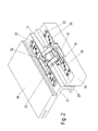
- FIGS. 1 to 6 a first embodiment of a door hinge according to the invention is shown, with which a door leaf 19 is preferably completely, that is 180 ° pivotally connected to a fixed door frame 21.
- the end face of the door leaf 19, in which a part of the door hinge is embedded, has a fold 20 which completely conceals the door hinge in the closed state of the door.
- the door hinge consists essentially of a preferably in an end face of the door leaf 19 of the door usable first housing 1 and a usable in the door frame 21 of the door second housing 2, which are interconnected by a multi-axis joint 3, wherein the shape and arrangement of Rotary axes of the joint 3 is designed such that the door leaf 19 is guided during opening so that the door rebate 20 does not collide with the door frame 21 and initially pivoted when opening of the door frame 21 away and at the end of the opening process again moves to the door frame 21 ,
- the housing 1, 2 are connected via respective mounting plates 4, 5 with the door leaf 19 and the door frame 21.
- the multi-axis joint 3 consists essentially of two joint members with respective joint main bodies 12, 13 and other joint bodies 14, 15.
- the second joint member has a second joint main body 13 and the pivotally connected via the rotation axis 16 hinge body 14, wherein the second joint main body 13 is rotatably connected via a second axis of rotation 8 with the second housing 2.
- first joint main body 12 is rotatably connected to the second joint main body 13 via a third rotation axis 9.
- the door leaf 19 performs during opening and closing a rotational movement and a superimposed longitudinal movement.
- the width of the housing 1, 2 is executable so that the housing 1, 2 in the narrow or front side of the door leaf 19 next to the door rebate 20 or in the opposite opposite with the door closed door area 21 are embedded can and preferably not exceed a width of 26mm.
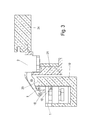
- the hinge main body 12, 13 are preferably arcuately and / or fork-shaped. This makes it possible that with the door closed, as in FIG. 4 shown that
- Joint main body 12, 13 in recesses 31, 32 in the housings 1, 2 are.
- the joint main body 12, 13 do not collide with each other during the movement process.
- the two joint main body 12, 13 are rotatably connected to each other via a rotation axis 9 and mounted to the housing 1, 2 via the axes of rotation 7 and 8 in the housings 1, 2.
- the joint body 14 and 15 are mounted on the axes of rotation 10 and 11 in the housings 1, 2.
- the axes of rotation 7, 8, 10 and 11 are fixedly mounted in the housings 1, 2.
- the axes of rotation 9, 33 and 16 allow the rotation of the connected joint body 12, 13, 14, 15 but move when opening or closing the door in position to the housings 1, 2nd
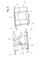
- the joint main body 12, 13 are connected to each other via the rotation axis 9 and formed fork-shaped or comb-shaped, so that the hinge fingers 25 and 27 of the first and second hinge member are in one another.
- the joint fingers 25 of the first joint member thereby enclose the one-piece joint finger 27 of the second joint member.
- the joint main body 12, 13 have in the region of the axes of rotation 8 and 7 on a joint body base 24, 26 which enclose the rotation axes 7, 8 over the entire available length and thereby ensure high strength, because the axes of rotation 8 and 7, the main burden the housing 1, 2 transmitted.
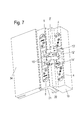
- the joint main body 12 ', 13' are formed so that in contrast to in the FIGS. 1 to 6
- the joint main bodies 12 ', 13' engage in one another such that the joint fingers 25 'of the first joint member are arranged next to the two joint fingers 27 of the second joint member.
- two joint bodies 14 'of the first joint member are provided in addition to the joint fingers 25'.
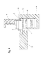
- a recess 23 is laterally introduced into the housing 2, which extends over the length of the pocket 32 and in which the axis of rotation 8 is located.
- the hinge main body 12 rotates in the recess 23 and thus has sufficient space to allow the opening.
- the adjustment of the door hinge is done by moving the housing 1, 2 relative to the mounting plates 4, 5, which are fixed in the door leaf 19 and the door frame 21.
- the housing 1 is displaced by the rotation of the spindles 29 in the z-direction, the spindles 29 are screwed through suitable threaded openings in the lugs 6 and stored in the back plates, which lie behind the lugs 6.
- the housing 2 is displaced by loosening the retaining screws 29, since the retaining screws 29 are guided by suitable elongated holes in the lugs 8, which provide sufficient space for displacement.
- the retaining screws 29 are bolted to back plates that lie behind the lugs and clamp the lugs when tightening the screws 29 between the mounting plates and the back plates.
- the housing 2 can be designed so displaceable in x and / or y-direction. Depending on the combination, the door hinge can be adjusted in one, two or three dimensions.
Priority Applications (1)
| Application Number | Priority Date | Filing Date | Title |
|---|---|---|---|
| EP11150705A EP2476837A1 (fr) | 2011-01-12 | 2011-01-12 | Penture |
Applications Claiming Priority (1)
| Application Number | Priority Date | Filing Date | Title |
|---|---|---|---|
| EP11150705A EP2476837A1 (fr) | 2011-01-12 | 2011-01-12 | Penture |
Publications (1)
| Publication Number | Publication Date |
|---|---|
| EP2476837A1 true EP2476837A1 (fr) | 2012-07-18 |
Family
ID=44122634
Family Applications (1)
| Application Number | Title | Priority Date | Filing Date |
|---|---|---|---|
| EP11150705A Withdrawn EP2476837A1 (fr) | 2011-01-12 | 2011-01-12 | Penture |
Country Status (1)
| Country | Link |
|---|---|
| EP (1) | EP2476837A1 (fr) |
Cited By (3)
| Publication number | Priority date | Publication date | Assignee | Title |
|---|---|---|---|---|
| CZ305075B6 (cs) * | 2013-12-05 | 2015-04-22 | Tokoz A.S. | Skrytý závěs |
| DE102017100254B3 (de) * | 2017-01-09 | 2018-01-04 | Simonswerk Gmbh | Türanordnung |
| EP4047165A1 (fr) * | 2021-02-18 | 2022-08-24 | Bartels Systembeschläge GmbH | Penture dissimulée de porte |
Citations (5)
| Publication number | Priority date | Publication date | Assignee | Title |
|---|---|---|---|---|
| GB426168A (en) * | 1933-07-03 | 1935-03-28 | Joseph Soss | Improvements in linkages for invisible hinges |
| CH401737A (de) * | 1961-09-22 | 1965-10-31 | J Soss Charles | Scharnier für verdeckte Anordnung |
| DE20213336U1 (de) * | 2001-08-31 | 2002-11-14 | Bartels Systembeschlaege Gmbh | Unsichtbares Türband mit zweidimensionaler Verstellung |
| DE102006062614A1 (de) | 2006-12-29 | 2008-07-03 | Bartels Systembeschläge GmbH | Türband für überfälzte Türen |
| DE202010010645U1 (de) * | 2009-07-30 | 2010-10-21 | Koblenz S.P.A., Coriano | Vollkommen versenkbares Scharnier mit Regulierung an drei Achsen für Türen und/oder Möbeltüren |
-
2011
- 2011-01-12 EP EP11150705A patent/EP2476837A1/fr not_active Withdrawn
Patent Citations (5)
| Publication number | Priority date | Publication date | Assignee | Title |
|---|---|---|---|---|
| GB426168A (en) * | 1933-07-03 | 1935-03-28 | Joseph Soss | Improvements in linkages for invisible hinges |
| CH401737A (de) * | 1961-09-22 | 1965-10-31 | J Soss Charles | Scharnier für verdeckte Anordnung |
| DE20213336U1 (de) * | 2001-08-31 | 2002-11-14 | Bartels Systembeschlaege Gmbh | Unsichtbares Türband mit zweidimensionaler Verstellung |
| DE102006062614A1 (de) | 2006-12-29 | 2008-07-03 | Bartels Systembeschläge GmbH | Türband für überfälzte Türen |
| DE202010010645U1 (de) * | 2009-07-30 | 2010-10-21 | Koblenz S.P.A., Coriano | Vollkommen versenkbares Scharnier mit Regulierung an drei Achsen für Türen und/oder Möbeltüren |
Cited By (5)
| Publication number | Priority date | Publication date | Assignee | Title |
|---|---|---|---|---|
| CZ305075B6 (cs) * | 2013-12-05 | 2015-04-22 | Tokoz A.S. | Skrytý závěs |
| DE102017100254B3 (de) * | 2017-01-09 | 2018-01-04 | Simonswerk Gmbh | Türanordnung |
| EP3346077A1 (fr) * | 2017-01-09 | 2018-07-11 | Simonswerk GmbH | Système de porte |
| EP3346077B1 (fr) | 2017-01-09 | 2020-09-02 | Simonswerk GmbH | Système de porte |
| EP4047165A1 (fr) * | 2021-02-18 | 2022-08-24 | Bartels Systembeschläge GmbH | Penture dissimulée de porte |
Similar Documents
| Publication | Publication Date | Title |
|---|---|---|
| EP1754848B1 (fr) | Charnière de porte pour arrangement caché entre battant et cadre de porte | |
| EP2476834B1 (fr) | Penture pour un agencement couvert entre une cadre de porte et un vantail | |
| AT12372U1 (de) | Vollkommen versenkbares, verbessertes scharnier mit positionseinstellung für türen und/oder möbeltüren | |
| EP3707331B1 (fr) | Paroi latérale d'un corps de meuble avec ferrure et meuble muni d'une paroi latérale | |
| AT12149U1 (de) | Vollkommen versenkbares scharnier mit einstellbarkeit in drei richtungen für türen und/oder möbeltüren | |
| DE102013008548B3 (de) | Dreidimensional verstellbares Beschlagsystem | |
| EP2257682B1 (fr) | Bande pour la fixation pivotante d'un vantail, d'une porte, d'une fenetre ou similaires, sur un cadre fixe | |
| DE112017004511B4 (de) | Schließvorrichtung | |
| AT506828B1 (de) | Türband für eine verdeckte anordnung zwischen türzarge und gefälztem türflügel | |
| EP2476836B1 (fr) | Penture | |
| WO2018208240A1 (fr) | Charnière avec protection anti-pincement et procédé de positionnement des parties de fixation d'une charnière | |
| EP2476837A1 (fr) | Penture | |
| EP3680431B1 (fr) | Bande de recouvrement pour portes | |
| EP0398193B1 (fr) | Charnière, notamment pour articuler une porte ou un volet à une paroi de suspension d'un corps | |
| EP3737816B1 (fr) | Charnière de meuble, panneau de meuble et corps de meuble | |
| DE102014226590A1 (de) | Beschlag für Fenster und Türen | |
| EP2642054A2 (fr) | Penture pour un agencement couvert entre un cadre de porte et un vantail | |
| EP2615232B1 (fr) | Ferrure de palier d'angle | |
| EP2208843B1 (fr) | Charnière pour une porte | |
| DE202011111002U1 (de) | Türband | |
| DE10143922B4 (de) | Scharnier | |
| DE102018119025B3 (de) | Scharnier zur gelenkigen Verbindung von Maschinenverkleidungswandteilen und/oder von Maschinentüren | |
| DE10301046B4 (de) | Drehbeschlag für die verdeckte Anordnung an Türen oder Fenstern | |
| EP2740872A2 (fr) | Palier d'angle prévu pour l'agencement recouvert | |
| AT516068B1 (de) | Verdeckttürband |
Legal Events
| Date | Code | Title | Description |
|---|---|---|---|
| PUAI | Public reference made under article 153(3) epc to a published international application that has entered the european phase |
Free format text: ORIGINAL CODE: 0009012 |
|
| AK | Designated contracting states |
Kind code of ref document: A1 Designated state(s): AL AT BE BG CH CY CZ DE DK EE ES FI FR GB GR HR HU IE IS IT LI LT LU LV MC MK MT NL NO PL PT RO RS SE SI SK SM TR |
|
| AX | Request for extension of the european patent |
Extension state: BA ME |
|
| 17P | Request for examination filed |
Effective date: 20121128 |
|
| 17Q | First examination report despatched |
Effective date: 20170309 |
|
| STAA | Information on the status of an ep patent application or granted ep patent |
Free format text: STATUS: THE APPLICATION IS DEEMED TO BE WITHDRAWN |
|
| 18D | Application deemed to be withdrawn |
Effective date: 20180404 |