EP2474338B1 - Microneedle array applicator device - Google Patents
Microneedle array applicator device Download PDFInfo
- Publication number
- EP2474338B1 EP2474338B1 EP12163072.7A EP12163072A EP2474338B1 EP 2474338 B1 EP2474338 B1 EP 2474338B1 EP 12163072 A EP12163072 A EP 12163072A EP 2474338 B1 EP2474338 B1 EP 2474338B1
- Authority
- EP
- European Patent Office
- Prior art keywords
- patch
- impactor
- microneedle array
- drive member
- housing
- Prior art date
- Legal status (The legal status is an assumption and is not a legal conclusion. Google has not performed a legal analysis and makes no representation as to the accuracy of the status listed.)
- Not-in-force
Links
Images


Classifications
-
- A—HUMAN NECESSITIES
- A61—MEDICAL OR VETERINARY SCIENCE; HYGIENE
- A61M—DEVICES FOR INTRODUCING MEDIA INTO, OR ONTO, THE BODY; DEVICES FOR TRANSDUCING BODY MEDIA OR FOR TAKING MEDIA FROM THE BODY; DEVICES FOR PRODUCING OR ENDING SLEEP OR STUPOR
- A61M5/00—Devices for bringing media into the body in a subcutaneous, intra-vascular or intramuscular way; Accessories therefor, e.g. filling or cleaning devices, arm-rests
- A61M5/14—Infusion devices, e.g. infusing by gravity; Blood infusion; Accessories therefor
- A61M5/158—Needles for infusions; Accessories therefor, e.g. for inserting infusion needles, or for holding them on the body
-
- A—HUMAN NECESSITIES
- A61—MEDICAL OR VETERINARY SCIENCE; HYGIENE
- A61B—DIAGNOSIS; SURGERY; IDENTIFICATION
- A61B17/00—Surgical instruments, devices or methods, e.g. tourniquets
- A61B17/20—Surgical instruments, devices or methods, e.g. tourniquets for vaccinating or cleaning the skin previous to the vaccination
- A61B17/205—Vaccinating by means of needles or other puncturing devices
-
- A—HUMAN NECESSITIES
- A61—MEDICAL OR VETERINARY SCIENCE; HYGIENE
- A61M—DEVICES FOR INTRODUCING MEDIA INTO, OR ONTO, THE BODY; DEVICES FOR TRANSDUCING BODY MEDIA OR FOR TAKING MEDIA FROM THE BODY; DEVICES FOR PRODUCING OR ENDING SLEEP OR STUPOR
- A61M37/00—Other apparatus for introducing media into the body; Percutany, i.e. introducing medicines into the body by diffusion through the skin
- A61M37/0015—Other apparatus for introducing media into the body; Percutany, i.e. introducing medicines into the body by diffusion through the skin by using microneedles
-
- A—HUMAN NECESSITIES
- A61—MEDICAL OR VETERINARY SCIENCE; HYGIENE
- A61M—DEVICES FOR INTRODUCING MEDIA INTO, OR ONTO, THE BODY; DEVICES FOR TRANSDUCING BODY MEDIA OR FOR TAKING MEDIA FROM THE BODY; DEVICES FOR PRODUCING OR ENDING SLEEP OR STUPOR
- A61M5/00—Devices for bringing media into the body in a subcutaneous, intra-vascular or intramuscular way; Accessories therefor, e.g. filling or cleaning devices, arm-rests
- A61M5/14—Infusion devices, e.g. infusing by gravity; Blood infusion; Accessories therefor
- A61M5/158—Needles for infusions; Accessories therefor, e.g. for inserting infusion needles, or for holding them on the body
- A61M2005/1585—Needle inserters
-
- A—HUMAN NECESSITIES
- A61—MEDICAL OR VETERINARY SCIENCE; HYGIENE
- A61M—DEVICES FOR INTRODUCING MEDIA INTO, OR ONTO, THE BODY; DEVICES FOR TRANSDUCING BODY MEDIA OR FOR TAKING MEDIA FROM THE BODY; DEVICES FOR PRODUCING OR ENDING SLEEP OR STUPOR
- A61M37/00—Other apparatus for introducing media into the body; Percutany, i.e. introducing medicines into the body by diffusion through the skin
- A61M37/0015—Other apparatus for introducing media into the body; Percutany, i.e. introducing medicines into the body by diffusion through the skin by using microneedles
- A61M2037/0023—Drug applicators using microneedles
Definitions
- the present invention relates to microneedle array applicators and methods of application of microneedle arrays.
- stratum corneum the outermost layer of the skin.
- microneedles arrays of relatively small structures, sometimes referred to as microneedles or micro-pins, have been disclosed for use in connection with the delivery of therapeutic agents and other substances through the skin and other surfaces.
- the devices are typically pressed against the skin in an effort to pierce the stratum corneum such that the therapeutic agents and other substances can pass through the stratum corneum and into the tissues below.
- Microneedles can be delivered using a patch that carries the microneedle array, which can facilitate delivery of therapeutic agents and other substances.
- Microneedle arrays and patches can be deployed with an applicator device capable of being used a number of different times.
- the microneedle arrays and patches are generally used once and then discarded.
- the applicator devices can be repeatedly reloaded with new microneedle arrays and patches.
- WO 2004/009172 A1 teaches an application device according to the preamble of claim 1.
- WO 2005/123173 A1 represents prior art under Article 54(3) EPC.
- the impactor (42) disclosed therein, however, is not capable of moving along an arcuate path.
- the present invention provides an alternative microneedle array applicator device.
- the invention comprises an application device as defined in claim 1.
- the microneedle array application device includes a housing and an impactor.
- the housing has a skin-contacting face that defines an opening that can be positioned at a target site.
- the impactor is capable of impacting a microneedle array and accelerating the microneedle array toward the target site.
- the impactor is further capable of moving along an arcuate path to move the microneedle array toward the target site.
- the microneedle array application device includes a housing having a surface-contacting face with an opening and a drive member having a length extending from a fixed end attached to the housing to a movable end.
- the drive member is bendable along its length and the movable end of the drive member is configured so as to be able to contact and propel a microneedle array.
- the drive member comprises a leaf spring.
- the applicator device includes a housing, an impactor pivotally supported by the housing, and a torsion spring.
- the impactor has an impacting portion that is capable of moving along a substantially arcuate path between a first position and a second position.
- the torsion spring is capable of biasing the impactor relative to the housing.
- the recess is defined along the skin-contacting face of the housing, and the recess has a bottom portion.
- An opening is defined in the bottom portion of the recess, and the opening can be positioned over a target site.
- At least one retaining surface is disposed along the bottom portion of the recess and adjacent to the opening, for holding a patch carrying a microneedle array prior to application at the target site.
- the retaining surface is generally parallel to the bottom portion of the recess, and the microneedle array can be aligned below the opening.
- the impactor comprises a magnet suitable for releasably retaining a magnetic microneedle patch.
- a method of microneedle array application includes providing a microneedle application device capable of bringing a microneedle array toward a target site, mounting the microneedle array on the microneedle array application device, and moving the impactor along a substantially arcuate path to bring the microneedle array into contact with the target site.
- Microneedle arrays can be used for transdermal or intradermal delivery of molecules, and in particular may have utility for the delivery of large molecules that are ordinarily difficult to deliver by passive transdermal delivery.
- the microneedle arrays may be applied as part of a microneedle device which, for example, may be in the form of a patch designed to adhere to skin and help keep the array in intimate contact with the skin.
- array refers to the medical devices described herein that include one or more structures capable of piercing the stratum corneum to facilitate the transdermal delivery of therapeutic agents or the sampling of fluids through or to the skin.
- Microstructure refers to the specific microscopic structures associated with the array that are capable of piercing the stratum corneum to facilitate the transdermal delivery of therapeutic agents or the sampling of fluids through the skin.
- microstructures can include needle or needle-like structures as well as other structures capable of piercing the stratum corneum.
- Microneedle arrays can be deployed using an applicator device that moves microneedle arrays into contact with a target location, such as a location on a patient's skin.
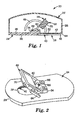
- FIG. 1 is a cross-sectional view of an applicator device 20 having a housing 22 that includes a base 24 and an upper cover structure 26.
- the base 24 is generally rectangular in shape, and has a recess 28 located on a bottom face 30 thereof.
- a generally circular opening 32 is defined in the recess 28 of the base 24.
- a raised portion 34 is formed on an upper face 36 of the base 24 for holding a patch accelerating or patch applicator assembly 38.
- a mounting structure or retaining portion of the applicator device 20 is formed by a pair of retainers 40, also referred to as a first retainer and a second retainer, connected to the base 24 (only one retainer 40 is visible in FIG. 1 ).
- the retainer members 40 are generally elongate and each have a substantially flat upper surface 42 that is generally parallel to and facing a bottom portion 44 of the recess 28, and is spaced from the bottom face 30 (i.e., the skin-contacting face) of the base 24.
- the pair of retainer members 40 are located on opposite sides of the opening 32 and are connected to the base 24 at one side of the recess 28.
- the retainer members 40 define an opening 46 at one end for accepting patches between the retainer members 40 and the bottom portion 44 of the recess 28.
- the upper surfaces 42 of the retainer members 40 may be non-stick or release surfaces.
- a non-stick or release surface can be achieved, for example, by a non-stick or release coating applied to the upper surfaces 42.
- the non-stick or release coating can be selected according to the desired use of the applicator device 20.
- a release coating such as a low surface energy silicone, fluoropolymer, or fluoro-silicone release coating, can be selected based upon the adhesives used with patches applied using the patch application device 20.
- a blade or other cutting means can be provided as part of the mounting structure, for separating portions of items from patches mounted on the applicator.
- the upper cover structure 26 is connected to the base 24 at or near a perimeter of the base 24.
- the upper cover structure 26 is shaped to fit on the base 24, and defines a volume, which is selected to provide space for the patch accelerating assembly 38.
- the housing 22 may also provide space for storing patches (e.g., a roll of patches) for eventual deployment by the applicator device 20.
- a slot 48 is defined in a side portion of the upper cover structure 26. In the embodiment shown in FIG. 1 , the slot 48 is arcuate in shape and generally resembles a half circle, with the open portion of the half circle facing the base 24 of the housing 22.
- Both the base 24 and the upper cover structure 26 can be formed of a polymer material.
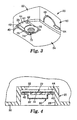
- FIG. 2 is a perspective view of a portion of the applicator device 20 with the upper cover portion 26 omitted to show interior portions of the device 20.
- the patch acceleration assembly 38 includes a frame member 60, an impactor 62, a handle 64, a bracket 66, and a torsion spring 68.
- the torsion spring 68 serves as a drive member to bias the impactor relative to the housing.
- the bracket 66 is mounted to the raised portion 34 of the base 24 of the housing 22 and pivotally retains the frame member 60. In some instances the bracket 66 may be directly affixed to the base 24, for example, if the base has sufficient thickness to allow for placement of the torsion spring 68.
- the frame member 60 can be a wire formed as a rectangular loop.
- the impactor 62 is attached to the frame member 60 opposite the bracket 66, and is the portion of the patch acceleration assembly 38 that interfaces with a patch to move it (i.e., to accelerate it), that is, it is the patch contacting portion of the device.
- the impactor 62 has a patch contacting surface 70 that is configured according to characteristics of a desired application, for instance, based upon the shape of a patch to be applied. In the embodiment shown in Figure 1 , the patch contacting surface 70 is configured so that it is generally parallel to and aligned with the frame member 60. Furthermore, it will be generally aligned with the bottom face 30 of the device 20 when fully deployed.
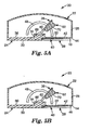
- the patch contacting surface 70 may be configured so that it is at another angle with respect to the frame member 60, and with respect to the bottom face 30 of the device 20 when fully deployed. Other such angles are shown in FIGS. 5A , B depicting a portion of devices having alternative patch contacting surfaces. In one embodiment, it may be desirable for the patch contacting surface 70 to be aligned so as to form an angle of between 4 and 15 degrees with the plane of the frame member. In one aspect, the angle of the patch contacting surface 70 may be selected so that it is aligned with the back of the a patch resting on retaining members 40 when the patch contacting surface 70 contacts the patch.
- the impactor 62 can be formed of a polymer material.
- the handle 64 extends from the impactor 62, and can be integrally formed with the impactor 62.
- the handle 64 is arranged to protrude through the slot 48 in the upper cover structure 26 of the housing 22, allowing the impactor 62 position to be manipulated from outside the housing 22.
- FIG. 1 simply represents one configuration for manipulating the patch acceleration assembly 38.
- a slot may be provided on the upper cover portion 26, thereby allowing the handle 64 or any other suitable actuation protrusion to protrude through the upper cover portion 26.
- the method for manipulating the patch acceleration assembly 38 need not be by means of a direct mechanical connection.
- various linkages or gears may be provided such that a button or knob on the exterior of the housing 22 may be pressed or turned to manipulate the patch acceleration assembly 38.
- the patch acceleration assembly 38 may be moved by a motor or solenoid that is electrically controlled by a button or knob on the exterior of the housing 22.
- the torsion spring 68 biases the frame 60 of the patch acceleration assembly 38 relative to the base 24 of the housing 22.
- the torsion spring 68 can be a conventional coiled spring steel torsion spring.
- the torsion spring 68 biases the frame 60, and therefore also the impactor 62, toward the opening 32 in the base 24 of the housing 22.
- the impactor In a substantially de-energized state, the impactor is at rest and positioned near the opening 32 in the base 24 of the housing 22.
- an operator can store potential energy in the torsion spring 68.
- Energy stored in the torsion spring 68 can be used to accelerate the impactor 62 toward a patch and also to accelerate a patch that has contacted the impactor 62.
- the amount of energy stored in the torsion spring 68 will vary depending on the amount of displacement of the impactor 62 away from the opening 32 and along the arcuate path.
- the appropriate torsion spring constant will depend upon a number of parameters, including the mass of the patch acceleration assembly, the mass of the patch, the arc length through which the patch acceleration assembly travels, and the desired speed of the patch on impact with a surface.
- the torsion spring constant will often be more than about 0.5 Newton*mm/degree and sometimes more than about 2.0 Newton*mm/degree.
- the torsion spring constant will often be less than about 5.0 Newton*mm/degree and sometimes less than about 4.0 Newton*mm/degree.
- the impactor 62 can be held at various points along the arcuate path either manually or, in some embodiments, with holding means (not shown) that engage and temporarily secure the handle 64 along the slot 48 in the upper cover structure 26 of the housing 22.
- demarcations or other indicators e.g., a force readout display
- the range of angular travel of the patch acceleration assembly will often be less than about 170 degrees and sometimes less than about 110 degrees.
- the range of angular travel of the patch acceleration assembly will often be more than about 10 degrees and sometimes more than about 60 degrees.
- the mass of the patch acceleration assembly will often be more than about 1 gram and sometimes more than about 5 grams.
- the mass of the patch acceleration assembly will often be less than about 100 grams and sometimes less than about 30 grams.
- FIG. 3 is a perspective view of a patch 72 (e.g., a patch 72 carrying a microneedle array 74) mounted on the applicator device 20.
- the patch 72 is disposed between the retainer members 40 and the bottom portion 44 of the recess 28 in the base 24 of the housing 22.
- the microneedle array 74 faces away from the opening 32 in the base 24 of the housing 22.
- the patch 72 which may have adhesive surrounding the microneedle array 74 on the surface facing away from the patch application device 20, contacts the upper surfaces 42 of the retainer members 40, but is generally not adhered firmly to the retainer members 40 due to the release character of the upper surfaces 42.
- microneedle array carried on the patch 72 is generally aligned relative to the opening 32 in the base 24 of the housing 22 (the opening 32 is not visible in FIG. 3 ).
- the retainer members 40 have cutaway portions 76 that provide an enlarged, partially circular open region that is generally aligned with the opening 32 on the bottom portion 44 of the recess 28 of the base 24 of the housing 22.
- the wider, open region defined by the cutaway portions 76 facilitates patch application by reducing the amount of deflection of the patch 72 required during deployment to move the patch 72 from a mounted position on the applicator device 20 to a target location.
- Such cutaway portions 76 are optional and may be unnecessary if, for example, the patch has a generally rectangular shape.
- FIG. 4 is a partial cross-sectional view of a microneedle array cartridge 80, having a patch 72 and a cover 82, mounted on the applicator device 20.
- Mounting the patch 72 on the applicator device 20 includes the following steps.
- the cartridge 80 is partially slid onto the retainer members 40.
- the cartridge 80 is slid further along the retainer members 40, simultaneously separating the cover 82 from the patch 72, until the patch 72 is fully mounted on the applicator device 20 (e.g., such that the microneedle array 74 is aligned with the opening 32 defined in the bottom portion 44 of the recess 28).
- the cover 82 is removed from (i.e., separated from) the patch 72 to uncover and expose the microneedle array 74 prior to microneedle deployment.
- the patch mounting structure shown in FIGS. 3 and 4 is provided by way of example, and not limitation.
- other means of mounting a patch on the applicator device 20 can be used, and the design of the mounting structure is generally independent of the design of other components of the applicator device 20.
- one or more patches can be stored inside the housing 22 prior to application, and then dispensed for application to a target site.
- the microneedle array 74 of the patch 72 can be deployed as follows. An operator "loads” or “energizes” the patch accelerating assembly 38 using the handle 64, to store potential energy in the torsion spring 68, by moving the impactor 62 and frame 60 along the arcuate path.
- the operator can "load" the patch accelerating assembly 38 either before or after the patch 72 is mounted to the device 20.
- the amount of energy stored in the torsion spring 68 can be selected based on characteristics of the desired patch application site, and may vary for different target sites, or may vary for different patches. Storing different amounts of energy in the torsion spring 68 permits adjustment of an acceleration rate of a patch moved by the patch accelerating assembly 38.
- the applicator device 20 is also positioned against an application surface, and the opening 32 is positioned relative to a target site for patch delivery. Suitable sites for microneedle patch application on a patient's skin will vary, and the operator must select a suitable position and orientation of the applicator device 20.
- the patch accelerating assembly 38 When the patch accelerating assembly 38 is energized, the patch 72 is fully mounted to the applicator device 20, and the device 20 is positioned relative to the target location, the operator then actuates the impactor 62 by releasing the energy stored in the torsion spring 68, which moves the impactor 62 toward the patch 72 along an arcuate path, which can correspond to the arcuate path defined by the slot 48 in the housing 22.
- the patch contacting surface 70 of the impactor 62 then contacts the patch 72 to transfer energy to the patch 72 and accelerate it toward the target site.
- Release of the stored energy may be by any suitable means, such as by pressing a button or turning a knob to release a latch or other locking mechanism and thereby allowing the patch accelerating assembly 38 to accelerate the patch 72 toward the target site.
- the arcuate path defined by the slot 48 is a portion (or arc) of a circle. It should be understood that in other embodiments the impactor may move along any type of arcuate (i.e., curved) path. Furthermore the path may be substantially arcuate, that is, although predominately curved, there may be small portions of the path which are not curved.
- the patch may be directly affixed or otherwise releasably held by the patch acceleration assembly.
- the patch may be releasably held to the impactor through magnetic attraction.
- the impactor may comprise a magnet and the patch may comprise a metal capable of magnetic attraction.
- the impactor for example, may be a permanent magnet or an electromagnet and the patch backing may comprise a metal that can be magnetically attracted.
- a thin layer of ferrous foil may be incorporated into the patch backing. Such a magnetic attraction can allow the patch to be held to the impactor until the patch contacts the skin.
- the adhesion between the patch and the skin can then be sufficient to allow the patch acceleration assembly, and thus the applicator, to be removed from the patch while allowing the patch to remain in place on the skin.
- the adhesive force between the patch and the skin is typically more than the magnetic, attractive force between the patch and the impactor. In some instances the adhesive force between patch and skin may be more than about twice as much as the magnetic, attractive force between patch and impactor. The appropriate amount of magnetic interaction may be readily determined, and will depend on a number of factors, including the magnitude of the adhesive force between the patch and the skin, the design of the applicator and its method of removal from the patch once the patch is applied to the skin.
- the patch may incorporate a magnet and the impactor can be made of a magnetic material, such as a steel leaf spring.
- Releasable magnetic attachment may be used with any of the hereinbefore or hereinafter describe embodiments, as well as with other embodiments of applicators, such as those described in United States Patent Application Publication 2002-0087182 and International Patent Publication WO 05/123173 , the disclosures of which are herein incorporated by reference.
- the patch may be releasably attached to a portion of the holding mechanism.
- the impactor may be an elongated drive member, such as a leaf spring having an opening or hole in its movable end.
- the patch may have a stub or other protrusion extending from its back surface that can be placed through the opening or hole in the leaf spring and gripped by the holding mechanism. The leaf spring will then also be held in place in a cocked position, as it will be pinned between the patch and the holding mechanism.
- a single use, disposable unit may be provided with the patch accelerating assembly 38 already in an energized position, so that the device may be positioned and fired with the press of a button.
- the patch 72 can be moved toward the target site along an at least partially arcuate path, such as when the patch 72 is moved in contact with the impactor 62 as the impactor 62 moves along its arcuate path.
- the patch 72 could also move linearly toward the target site after contacting the impactor 62, such as where the impactor 62 momentarily contacts the patch 72 and transfers its kinetic energy to the patch 72 (which then travels along a generally linear path that differs from the arcuate path of the impactor 62).
- the deployed patch 72 can be adhered to the target site, as desired for delivery of molecules.
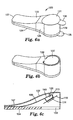
- FIG. 6A is a perspective view of another embodiment of an applicator device 120 having a housing 122 that includes a base 124 and an upper cover structure 126.
- the device is elongate in shape and has a first, tapered end 127 and a second end 129.
- the second end 129 has a top and bottom sealed by a top peelable seal 131 having a tab 133 and a bottom peelable seal 132 having a tab 135 (only tab 135 is visible in FIG. 6A).
- FIG. 6B shows the applicator device after the peelable seals 131, 132 have been removed.
- a trigger 137 is integrally formed in the top surface of the housing 122.
- the trigger is connected to the top surface of the housing at a single attachment point 139, thus allowing the trigger to be deflected downward by thumb or finger pressure as shown in FIG. 6D .
- FIG. 6C is a cross-sectional view of the device showing a patch 172 mounted on an impactor 170.
- the impactor 170 is integrally formed with a drive member 166 having a length extending from a fixed end 167 attached to the housing 122 to a movable end 169.
- the drive member 166 is bendable along its length.
- a holding mechanism in the form of a latch uses a hook 125 attached to the housing 122.
- the hook 125 engages with a slot 171 in the movable end 169 of the drive member 166 to hold the movable end 169 of the drive member 166 away from the skin-contacting face 124 of the housing 122.
- the drive member may be any elongate, bendable member, such as, for example, a leaf spring.
- FIG. 6C In use the device as shown in FIG. 6C is placed against a target surface, such as a skin surface (not shown). Depression of the trigger 137, as shown in FIG. 6D , causes the hook 125 to pivot, thus releasing the movable end 169 of the drive member 166 and allowing the drive member 166 to bias the patch 172 towards the skin-contacting face 124.
- FIG. 6E shows the drive member 166 fully deployed, having propelled the patch 172 past the skin-contacting face 124 so that the patch is pressed against the skin surface (not shown).
- FIG. 6F shows the device 120 being removed from the skin surface 181, leaving a patch 172 with a microneedle array 174 in place on the skin surface 181.
- the impactor 170 is shown as a curled end of a leaf spring, as this allows for a convenient means for providing a holding mechanism (via the slot 171 in the movable end 169 of the leaf spring) while also providing a separate patch contacting and holding surface.
- any variety of suitable shapes may be used for the movable end 169 of the drive member 166, including a flat leaf spring having no curled end.
- FIG. 7A is a perspective top view of another embodiment of an applicator device 220 having a housing 222 that includes a base 224 and an upper cover structure 226.
- a trigger 237 extends from the upper cover structure 226.
- FIG. 7B is perspective bottom view of the applicator 220 showing a handle 249 and having retainers 240 for holding a microneedle patch 272 with a microneedle array 274, similar to the patch retaining structure shown in FIG. 3 .
- FIG. 7C is a cross-sectional view showing an impactor 270 integrally formed with a drive member 266 having a length extending from a fixed end 267 attached to the housing 222 to a movable end 269. The drive member 266 is bendable along its length.
- a holding mechanism in the form of a latch uses a hook 225 attached to the housing 222.
- the hook 225 engages with a slot 271 in the movable end 269 of the drive member 266 to hold the movable end 269 of the drive member 266 away from the skin-contacting face 224 of the housing 222.
- a lifting mechanism 251 is shown in a raised position.
- the lifting mechanism 251 is operably connected to the handle 249 (shown in dashed lines on the back side of the applicator) and is also configured so that it can lift the drive member 266 into a position such as shown in FIG. 7C , where the drive member 266 has been raised and latched onto hook 225. In use the device as shown in FIG.
- FIG. 7C is placed against a target surface, such as a skin surface (not shown).
- the handle 249 may be released, thereby releasing the lifting mechanism 251 to a lowered position, such as shown in FIG. 7D .
- the trigger 237 may be pushed sideways, as shown in FIG. 7D , thus releasing the movable end 269 of the drive member 266 and allowing the drive member 266 to bias the impactor 270 towards the patch 272 and the skin-contacting face 224.
- the impactor 270 drives the patch 272 from the retainers 240 and past the skin-contacting face 224 so that the patch is pressed against the skin surface (not shown).
- FIG. 7E shows the device 220 being removed from the skin surface 281, leaving a patch 272 with a microneedle array 274 in place on the skin surface 281.
- the applicator 220 may be used for applying multiple patches in the following manner. After application of a patch, the handle 249 may be lifted, thereby raising the lifting mechanism 251 and thus the drive member 266 to a raised position, such as shown in FIG. 7C , and the trigger 237 may be pushed back into place to lock the drive member 266 in a raised position.
- the trigger 237 may be manually moved into position to lock the drive member 266.
- the trigger 237 may be moved into position to lock the drive member 266 by a spring (not shown) that biases it towards the locked position or by a mechanism (not shown) connected to the handle 249 which causes the trigger 237 to move to the locked position as the drive member 266 is raised by the handle. Any other suitable triggers and re-cocking mechanisms may be employed.
- Another patch may then be loaded into the retaining mechanism and applied as described above.
- the applicator device of the present invention may provide numerous benefits and advantages.
- the housing may be shaped in a way that generally resembles a mouse for a personal computer. This shape is less threatening to patients than applicators or other drug delivery devices that are shaped, for example, like a gun.
- the housing also provides adequate interior volume for protecting the patch accelerating assembly and can optionally provide storage space for patches prior to application. Patch mounting may be quickly and easily accomplished, which is helpful for mass inoculations and other applications. It should be understood, however, that any suitable housing shape may be used.
- the housing may have a circular, square, or rectangular cross-section in some embodiments and may be a polyhedron in certain embodiments (i.e., the housing may define a volume formed by plane faces).
- the housing may be a polyhedron having one or more rectangular faces, that is, a rectangular polyhedron.
- the housing may have a flat or planar base with sides that are continuously curved. It is preferred, but not necessary, that the patch accelerating assembly is fully contained (with the exception of the handle) within the housing.
- a torsion spring or leaf spring allows for simple and efficient adjustment of force used to apply patch with the applicator device, permitting the applicator device to be used in a variety of contexts and for patch application to a variety of desired patch sites.
- a method of applying a microneedle array using an application device of the present invention comprises mounting the microneedle array on the microneedle array application device and moving the microneedle array toward the target site along a substantially arcuate path.
- the array for example, may be affixed to an impactor within the device, as described above. Release of the impactor allows the array to travel towards the target site along a substantially arcuate path.
- a method of applying a microneedle array using an application device of the present invention comprises mounting the microneedle array on the microneedle array application device and moving the impactor along a substantially arcuate path to bring the microneedle array into contact with the target site.
- the array may be mounted within the application device using a retainer separate from the impactor, such as shown in FIG. 3 , and the impactor may be placed in a loaded position (i.e., where it contains stored energy) and then released so as to travel along an arcuate path. The impactor will then contact the microneedle array (or a patch holding the microneedle array) and bring the microneedle array into contact with the target site.
- a method of applying a microneedle array using an application device of the present invention comprises placing a microneedle patch on or adjacent to a target site.
- An application device of the present invention may be brought into alignment with the microneedle array and triggered so as to cause the impactor to press the microneedle array into the target site.
- the microneedle patch may be held in place on a skin surface prior to contacting it with the application device by any suitable means, such as with use of a collapsible patch as described in United States Patent Application Serial No. 60/693,901, filed on June 24, 2005 , the disclosure of which is herein incorporated by reference.
- a method of applying a microneedle array using an application device of the present invention involves having the microneedle array reach a desired velocity that is effective to pierce the microneedles into the skin.
- the desired velocity is preferably controlled to limit or prevent stimulation of the underlying nerve tissue.
- the maximum velocity achieved by the microneedle array upon impact with the skin is often 20 meters per second (m/s) or less, potentially 15 m/s or less, and possibly 10 m/s or less. In some instances, the maximum velocity is 8 m/s or less. In other instances, the minimum velocity achieved by the microneedle array upon impact with the skin is often 2 m/s or more, potentially 4 m/s or more, and possibly 6 m/s or more.
- the mass of the portion of the device driving the microneedle array into the skin is preferably light enough to avoid causing undue discomfort to a patient.
- the mass of the impactor is less than about 6 grams, potentially less than about 4 grams, and possibly less than about 2 grams.
- the mass of the impactor is typically more than about 0.4 grams, potentially more than about 0.8 grams, and possibly greater than about 1.2 gram.
- the impactor will generally be considered to include the portion above and behind the microneedle array, but not to include the portion of the drive member extending away from the movable end of the drive member and towards the fixed end of the drive member.
- the velocity achieved by the microneedle array upon impact with the skin will be between about 4 m/s and 8 m/s, and the mass of the impactor will be between about 0.4 grams and about 2 grams.
- Use of a leaf spring as a drive member directly coupled to a microneedle patch may be particularly advantageous, as this allows the device to obtain desired velocities upon impact with the skin in combination with a relatively low mass impactor.
- Such high-speed, low-mass delivery may be particularly advantageous when applying a microneedle array having a large number of microneedles. While not wishing to be bound by theory, it is believed that the momentum of an array having a large number of microneedles can be quite low and still achieve acceptable penetration of the microneedles through the stratum corneum, because each microneedle has a very tiny mass and only penetrates a relatively short distance into the skin. In particular, insertion of microneedle arrays having more than 100 microneedles, often more than 500 microneedles, and occasionally more than 1000 microneedles may be particularly effective when performed using devices as described above.
- the depth of penetration of the microneedles will vary depending on a number of factors, such as the size and design of both the microneedles and the microneedle array, as well as upon the velocity with which the array impacts the skin.
- the microneedles will penetrate to a depth of more than 40 ⁇ m, sometimes more than 80 ⁇ m, and occasionally more than 100 ⁇ m.
- the microneedles will penetrate to a depth of less than 300 ⁇ m, sometimes less than 200 ⁇ m, and occasionally less than 150 ⁇ m.
- the microneedles will penetrate to a depth that is more than 20% of the full height of the microneedle, sometimes more than 40%, and occasionally more than 50%.
- the microneedles will penetrate to a depth that is less than about 80% of the full height of the microneedle, sometimes less than 60%, and occasionally less than 50%.
- the microneedles are typically less than 500 microns in height, and sometimes less than 300 microns in height.
- the microneedles are typically more than 20 microns in height, often more than 50 microns in height, and sometimes more than microns in height.
- the height of the microneedles may be measured as the distance that they protrude from a flat base or substrate.
- the microneedles may protrude from an irregular substrate, for example, each microneedle may rest upon a flat base or pedestal that itself protrudes from a planar substrate.
- the application device be designed such that the microneedle array travels at a velocity at or above the desired minimum velocities over a distance that is sufficient to accommodate the variations in skin location and appendage size relative to the application device.
- the microneedle array in the application device may move at or above the minimum velocity over a distance of one millimeter or more. In some embodiments, the microneedle array may move at or above the minimum velocity over a distance of 5 millimeters or more.
- microneedle arrays useful in the various embodiments of the invention may comprise any of a variety of configurations, such as those described in the following patents and patent applications, the disclosures of which are herein incorporated by reference.
- One embodiment for the microneedle arrays comprises the structures disclosed in United States Patent Application Publication No. 2003/0045837 .
- the disclosed microstructures in the aforementioned patent application are in the form of microneedles having tapered structures that include at least one channel formed in the outside surface of each microneedle.
- the microneedles may have bases that are elongated in one direction.
- the channels in microneedles with elongated bases may extend from one of the ends of the elongated bases towards the tips of the microneedles.
- the channels formed along the sides of the microneedles may optionally be terminated short of the tips of the microneedles.
- the microneedle arrays may also include conduit structures formed on the surface of the substrate on which the microneedle array is located. The channels in the microneedles may be in fluid communication with the conduit structures.
- Another embodiment for the microneedle arrays comprises the structures disclosed U. S. Patent Application Publication No. 2005/0261631 , which describes microneedles having a truncated tapered shape and a controlled aspect ratio.
- Still another embodiment for the microneedle arrays comprises the structures disclosed in United States Patent No. 6,091,975 (Daddona, et al. ) which describes blade-like microprotrusions for piercing the skin.
- Still another embodiment for the microneedle devices comprises the structures disclosed in United States Patent No. 6,313,612 (Sherman, et al. ) which describes tapered structures having a hollow central channel. Still another embodiment for the micro arrays comprises the structures disclosed in U. S. Patent No. 6,379,324 (Gartstein, et al. ) which describes hollow microneedles having at least one longitudinal blade at the top surface of tip of the microneedle.
- Microneedle arrays and microneedle patches of the present invention may be used to deliver drugs (including any pharmacological agent or agents) through the skin in a variation on transdermal delivery, or to the skin for intradermal or topical treatment, such as vaccination.
- drugs that are of a large molecular weight may be delivered transdermally. Increasing molecular weight of a drug typically causes a decrease in unassisted transdermal delivery.
- Microneedle arrays of the present invention have utility for the delivery of large molecules that are ordinarily difficult to deliver by passive transdermal delivery. Examples of such large molecules include proteins, peptides, nucleotide sequences, monoclonal antibodies, DNA vaccines, polysaccharides, such as heparin, and antibiotics, such as ceftriaxone.
- microneedle arrays and microneedle patches of the present invention may have utility for enhancing or allowing transdermal delivery of small molecules that are otherwise difficult or impossible to deliver by passive transdermal delivery.
- molecules include salt forms; ionic molecules, such as bisphosphonates, preferably sodium alendronate or pamedronate; and molecules with physicochemical properties that are not conducive to passive transdermal delivery.
- microneedle arrays and microneedle patches of the present invention may have utility for enhancing delivery of molecules to the skin, such as in dermatological treatments, vaccine delivery, or in enhancing immune response of vaccine adjuvants.
- Microneedle arrays and microneedle patches may be used for immediate delivery, that is where they are applied and immediately removed from the application site, or they may be left in place for an extended time, which may range from a few minutes to as long as 1 week.
- an extended time of delivery may be from 1 to 30 minutes to allow for more complete delivery of a drug than can be obtained upon application and immediate removal.
- an extended time of delivery may be from 4 hours to 1 week to provide for a sustained release of drug.
Applications Claiming Priority (3)
| Application Number | Priority Date | Filing Date | Title |
|---|---|---|---|
| US69444705P | 2005-06-27 | 2005-06-27 | |
| US74629806P | 2006-05-03 | 2006-05-03 | |
| EP06773934A EP1901799B1 (en) | 2005-06-27 | 2006-06-23 | Microneedle array applicator device |
Related Parent Applications (1)
| Application Number | Title | Priority Date | Filing Date |
|---|---|---|---|
| EP06773934.2 Division | 2006-06-23 |
Publications (2)
| Publication Number | Publication Date |
|---|---|
| EP2474338A1 EP2474338A1 (en) | 2012-07-11 |
| EP2474338B1 true EP2474338B1 (en) | 2013-07-24 |
Family
ID=37054466
Family Applications (2)
| Application Number | Title | Priority Date | Filing Date |
|---|---|---|---|
| EP12163072.7A Not-in-force EP2474338B1 (en) | 2005-06-27 | 2006-06-23 | Microneedle array applicator device |
| EP06773934A Not-in-force EP1901799B1 (en) | 2005-06-27 | 2006-06-23 | Microneedle array applicator device |
Family Applications After (1)
| Application Number | Title | Priority Date | Filing Date |
|---|---|---|---|
| EP06773934A Not-in-force EP1901799B1 (en) | 2005-06-27 | 2006-06-23 | Microneedle array applicator device |
Country Status (7)
| Country | Link |
|---|---|
| US (2) | US8784363B2 (zh) |
| EP (2) | EP2474338B1 (zh) |
| JP (1) | JP5144510B2 (zh) |
| CN (1) | CN101208130B (zh) |
| AU (1) | AU2006261898B2 (zh) |
| CA (1) | CA2613111C (zh) |
| WO (1) | WO2007002521A2 (zh) |
Families Citing this family (98)
| Publication number | Priority date | Publication date | Assignee | Title |
|---|---|---|---|---|
| GB0402131D0 (en) | 2004-01-30 | 2004-03-03 | Isis Innovation | Delivery method |
| WO2006055795A1 (en) * | 2004-11-18 | 2006-05-26 | 3M Innovative Properties Company | Low-profile microneedle array applicator |
| WO2006108185A1 (en) | 2005-04-07 | 2006-10-12 | 3M Innovative Properties Company | System and method for tool feedback sensing |
| EP1896115B2 (en) | 2005-06-27 | 2020-01-22 | 3M Innovative Properties Company | Microneedle cartridge assembly |
| WO2007124411A1 (en) | 2006-04-20 | 2007-11-01 | 3M Innovative Properties Company | Device for applying a microneedle array |
| GB2448493B (en) | 2007-04-16 | 2009-10-14 | Dewan Fazlul Hoque Chowdhury | Microneedle transdermal delivery device |
| EP2146689B1 (en) | 2007-04-16 | 2020-08-12 | Corium, Inc. | Solvent-cast microneedle arrays containing active |
| US8911749B2 (en) | 2007-04-16 | 2014-12-16 | Corium International, Inc. | Vaccine delivery via microneedle arrays |
| US9220678B2 (en) | 2007-12-24 | 2015-12-29 | The University Of Queensland | Coating method |
| AU2009212106B9 (en) | 2008-02-07 | 2014-05-22 | Vaxxas Pty Limited | Patch production |
| AU2009250341A1 (en) | 2008-05-23 | 2009-11-26 | The University Of Queensland | Analyte detection using a needle projection patch |
| KR20190064676A (ko) | 2008-11-18 | 2019-06-10 | 쓰리엠 이노베이티브 프로퍼티즈 컴파니 | 중공 마이크로니들 어레이 |
| WO2010095456A1 (ja) | 2009-02-23 | 2010-08-26 | 株式会社メドレックス | 剣山型マイクロニードルのアプリケーター |
| WO2010101620A2 (en) | 2009-03-02 | 2010-09-10 | Seventh Sense Biosystems, Inc. | Systems and methods for creating and using suction blisters or other pooled regions of fluid within the skin |
| US9033898B2 (en) | 2010-06-23 | 2015-05-19 | Seventh Sense Biosystems, Inc. | Sampling devices and methods involving relatively little pain |
| US9041541B2 (en) | 2010-01-28 | 2015-05-26 | Seventh Sense Biosystems, Inc. | Monitoring or feedback systems and methods |
| BR112012001685B8 (pt) * | 2009-07-31 | 2021-06-22 | 3M Innovative Properties Co | conjuntos de microagulhas ocas |
| US20120184916A1 (en) | 2009-08-07 | 2012-07-19 | Medrx Co., Ltd. | Applicator device of pinholder type microneedle |
| CN103096970B (zh) | 2010-01-22 | 2016-10-26 | 株式会社医药处方 | 用于微针粘附皮肤贴剂的粘附贴剂辅助工具 |
| GB201007207D0 (en) * | 2010-04-29 | 2010-06-16 | Univ Cork | Method |
| RU2569029C2 (ru) * | 2010-05-04 | 2015-11-20 | Кориум Интернэшнл, Инк. | Аппликаторы для микроигл |
| JP6327852B2 (ja) | 2010-05-04 | 2018-05-23 | コリウム インターナショナル, インコーポレイテッド | 微小突起アレイを使用した副甲状腺ホルモンの経皮送達のための方法及びデバイス |
| JP5562138B2 (ja) | 2010-06-24 | 2014-07-30 | シスメックス株式会社 | 微細孔形成装置 |
| US9943673B2 (en) * | 2010-07-14 | 2018-04-17 | Vaxxas Pty Limited | Patch applying apparatus |
| CN103068308B (zh) | 2010-07-16 | 2016-03-16 | 第七感生物系统有限公司 | 用于流体传输装置的低压环境 |
| US20130158482A1 (en) | 2010-07-26 | 2013-06-20 | Seventh Sense Biosystems, Inc. | Rapid delivery and/or receiving of fluids |
| WO2012021801A2 (en) | 2010-08-13 | 2012-02-16 | Seventh Sense Biosystems, Inc. | Systems and techniques for monitoring subjects |
| US20120089118A1 (en) * | 2010-10-08 | 2012-04-12 | A Nevada Corporation | Delivery of bisphosphonates by microinjection systems |
| CN103370007B (zh) | 2010-11-09 | 2018-12-18 | 第七感生物系统有限公司 | 用于采血的系统和界面 |
| US9950109B2 (en) | 2010-11-30 | 2018-04-24 | Becton, Dickinson And Company | Slide-activated angled inserter and cantilevered ballistic insertion for intradermal drug infusion |
| US8814831B2 (en) | 2010-11-30 | 2014-08-26 | Becton, Dickinson And Company | Ballistic microneedle infusion device |
| US8795234B2 (en) | 2010-11-30 | 2014-08-05 | Becton, Dickinson And Company | Integrated spring-activated ballistic insertion for drug infusion device |
| WO2012075339A1 (en) * | 2010-12-02 | 2012-06-07 | Lanco Biosciences, Inc. | Delivery of heparins by microinjection systems |
| WO2012075209A1 (en) * | 2010-12-02 | 2012-06-07 | Lanco Biosciences, Inc. | Delivery of triptans by microinjection systems |
| WO2012075375A1 (en) * | 2010-12-02 | 2012-06-07 | Lanco Biosciences, Inc. | Delivery of parathyroid hormones by microinjection systems |
| WO2012074721A2 (en) * | 2010-12-02 | 2012-06-07 | Lanco Biosciences, Inc. | Delivery of serotonin receptor antagonists by microinjection systems |
| JP6082697B2 (ja) | 2010-12-22 | 2017-02-15 | バレリタス, インコーポレイテッド | 極微針パッチアプリケータ |
| IT1403293B1 (it) | 2010-12-27 | 2013-10-17 | Fond Don Carlo Gnocchi Onlus | Apparecchiatura ad aghi per la somministrazione transdermica di farmaci. |
| CN102727992A (zh) * | 2011-03-31 | 2012-10-17 | 株式会社汉比特科技与创新 | 印章式针组件 |
| CA2833175A1 (en) | 2011-04-29 | 2012-11-01 | Seventh Sense Biosystems, Inc. | Devices and methods for collection and/or manipulation of blood spots or other bodily fluids |
| US20130158468A1 (en) | 2011-12-19 | 2013-06-20 | Seventh Sense Biosystems, Inc. | Delivering and/or receiving material with respect to a subject surface |
| ES2597081T3 (es) | 2011-04-29 | 2017-01-13 | Seventh Sense Biosystems, Inc. | Entrega y/o recepción de fluidos |
| EP2701598A1 (en) | 2011-04-29 | 2014-03-05 | Seventh Sense Biosystems, Inc. | Systems and methods for collecting fluid from a subject |
| CN103764197B (zh) * | 2011-09-07 | 2017-03-15 | 3M创新有限公司 | 用于中空微针阵列的递送系统 |
| WO2013038890A1 (ja) * | 2011-09-16 | 2013-03-21 | 久光製薬株式会社 | アプリケータ |
| NL2007461C2 (en) | 2011-09-23 | 2013-03-26 | Ambro B V | System for transporting fluid across or into a biological barrier, device and capsule as part of the system. |
| CA2851606C (en) | 2011-10-12 | 2020-08-04 | 3M Innovative Properties Company | Integrated microneedle array delivery system |
| US11179553B2 (en) | 2011-10-12 | 2021-11-23 | Vaxxas Pty Limited | Delivery device |
| CA2851620A1 (en) * | 2011-10-12 | 2013-04-18 | 3M Innovative Properties Company | Integrated microneedle array delivery system |
| CA2896188C (en) | 2012-12-21 | 2021-02-23 | Corium International, Inc. | Microarray for delivery of therapeutic agent and methods of use |
| KR102158891B1 (ko) * | 2012-12-21 | 2020-09-22 | 히사미쓰 세이야꾸 가부시키가이샤 | 어플리케이터 |
| KR102236575B1 (ko) * | 2012-12-21 | 2021-04-05 | 쓰리엠 이노베이티브 프로퍼티즈 컴파니 | 접착제 조립체 및 이를 포함하는 마이크로니들 주사 장치 |
| US10105524B2 (en) | 2012-12-27 | 2018-10-23 | 3M Innovative Properties Company | Article with hollow microneedles and method of making |
| US10245422B2 (en) | 2013-03-12 | 2019-04-02 | Corium International, Inc. | Microprojection applicators and methods of use |
| US10384045B2 (en) | 2013-03-15 | 2019-08-20 | Corium, Inc. | Microarray with polymer-free microstructures, methods of making, and methods of use |
| EP2968751B1 (en) | 2013-03-15 | 2022-11-30 | Corium, Inc. | Multiple impact microprojection applicators |
| CA2906541C (en) | 2013-03-15 | 2022-06-21 | Corium International, Inc. | Microarray for delivery of therapeutic agent and methods of use |
| AU2014233541B2 (en) | 2013-03-15 | 2018-11-22 | Corium Pharma Solutions, Inc. | Microarray for delivery of therapeutic agent, methods of use, and methods of making |
| WO2014193729A1 (en) * | 2013-05-31 | 2014-12-04 | 3M Innovative Properties Company | Microneedle injection apparatus comprising an inverted actuator |
| JP6494601B2 (ja) | 2013-05-31 | 2019-04-03 | スリーエム イノベイティブ プロパティズ カンパニー | マイクロニードル注射及び注入装置並びにその使用方法 |
| SG11201509722PA (en) | 2013-05-31 | 2015-12-30 | 3M Innovative Properties Co | Microneedle injection apparatus comprising a dual cover |
| WO2015017561A1 (en) | 2013-07-30 | 2015-02-05 | Zosano Pharma, Inc. | Low-profile microneedle patch applicator |
| US10369278B2 (en) * | 2013-09-05 | 2019-08-06 | Sanofi-Aventis Deutschland Gmbh | Drive mechanism for a needle insertion arrangement |
| ES2756574T3 (es) | 2013-11-05 | 2020-04-27 | Hisamitsu Pharmaceutical Co | Aplicador |
| JP6199702B2 (ja) * | 2013-11-06 | 2017-09-20 | 久光製薬株式会社 | アプリケータ |
| CN106535979B (zh) | 2014-04-30 | 2018-12-21 | 金伯利-克拉克环球有限公司 | 透皮药物递送设备的控制器部分和方法 |
| US10624843B2 (en) | 2014-09-04 | 2020-04-21 | Corium, Inc. | Microstructure array, methods of making, and methods of use |
| US10292734B1 (en) | 2014-10-24 | 2019-05-21 | Verily Life Sciences Llc | Micro-structures with magnetic removal capability and optionally clear optical path |
| WO2016121499A1 (ja) * | 2015-01-27 | 2016-08-04 | 凸版印刷株式会社 | 経皮投与デバイス |
| EP4218892A1 (en) | 2015-02-02 | 2023-08-02 | Vaxxas Pty Limited | Microprojection array applicator |
| WO2017004067A1 (en) | 2015-06-29 | 2017-01-05 | Corium International, Inc. | Microarray for delivery of therapeutic agent, methods of use, and methods of making |
| USD776264S1 (en) | 2015-07-30 | 2017-01-10 | Becton, Dickinson And Company | Medical injector |
| USD776265S1 (en) | 2015-07-30 | 2017-01-10 | Becton, Dickinson And Company | Medical injector |
| USD776263S1 (en) | 2015-07-30 | 2017-01-10 | Becton, Dickinson And Company | Medical injector |
| USD776262S1 (en) | 2015-07-30 | 2017-01-10 | Becton, Dickinson And Company | Medical injector |
| USD774640S1 (en) | 2015-07-30 | 2016-12-20 | Becton, Dickinson And Company | Medical injector |
| USD794776S1 (en) | 2015-07-30 | 2017-08-15 | Becton, Dickinson And Company | Medical injector |
| USD767120S1 (en) | 2015-07-30 | 2016-09-20 | Becton, Dickinson And Company | Medical injector |
| KR102135518B1 (ko) | 2015-09-02 | 2020-07-17 | 히사미쓰 세이야꾸 가부시키가이샤 | 어플리케이터 |
| US11103259B2 (en) | 2015-09-18 | 2021-08-31 | Vaxxas Pty Limited | Microprojection arrays with microprojections having large surface area profiles |
| WO2018031529A1 (en) * | 2016-08-08 | 2018-02-15 | Avedro, Inc. | Systems and methods for cross-linking treatments of an eye |
| KR101746048B1 (ko) * | 2016-09-13 | 2017-06-12 | 주식회사 라파스 | 마이크로니들 패치 어플리케이터 |
| JP7152787B2 (ja) | 2017-03-31 | 2022-10-13 | ヴァクザス ピーティーワイ リミテッド | 表面をコーティングするための装置および方法 |
| US11175128B2 (en) | 2017-06-13 | 2021-11-16 | Vaxxas Pty Limited | Quality control of substrate coatings |
| JP7408398B2 (ja) | 2017-07-14 | 2024-01-05 | アムジエン・インコーポレーテツド | 二重ねじりばねシステムを有する針挿入後退システム |
| EP3661587A4 (en) | 2017-08-04 | 2021-06-09 | Vaxxas Pty Limited | COMPACT HIGH MECHANICAL ENERGY STORAGE AND LOW RELEASE FORCE ACTUATOR FOR MICROPROJECTION NETWORK (PRM) PATCH DELIVERY |
| DE102017007485A1 (de) * | 2017-08-09 | 2019-02-14 | Lts Lohmann Therapie-Systeme Ag | Adaptersystem mit Rahmen, Wirkstoffpad und Deckel |
| EP3718595B1 (en) * | 2017-11-30 | 2023-09-13 | Hisamitsu Pharmaceutical Co., Inc. | Applicator, cartridge, and application kit |
| US10786203B1 (en) * | 2018-01-30 | 2020-09-29 | Daniel M. Besser | Medical patch applicator device |
| WO2019166572A1 (en) | 2018-02-28 | 2019-09-06 | Pharming Intellectual Property B.V. | Pharmaceutical system for transdermal administration of a c1 -esterase inhibitor |
| DE102019001251A1 (de) | 2019-02-21 | 2020-08-27 | Lts Lohmann Therapie-Systeme Ag | Applikator für Mikronadelpflaster |
| JP2023504540A (ja) * | 2019-12-05 | 2023-02-03 | フォリカ,インコーポレーテッド | 穿刺装置及び侵入深さ |
| CN116390688A (zh) * | 2020-06-17 | 2023-07-04 | 比奥林股份有限公司 | 用于施用微针阵列的装置和方法 |
| US11389376B2 (en) | 2020-12-21 | 2022-07-19 | Mediccene Inc. | Wearable intravenous fluid delivery system |
| JP2024512870A (ja) * | 2021-09-28 | 2024-03-21 | バイオリンク インコーポレイテッド | 微小針アレイベースの持続的分析物監視デバイスのための微小針エンクロージャおよびアプリケータデバイス |
| US11877848B2 (en) | 2021-11-08 | 2024-01-23 | Satio, Inc. | Dermal patch for collecting a physiological sample |
| US11964121B2 (en) | 2021-10-13 | 2024-04-23 | Satio, Inc. | Mono dose dermal patch for pharmaceutical delivery |
| CN114081538B (zh) * | 2021-11-12 | 2023-09-15 | 江西中医药大学 | 一种用于皮肤组织液穿刺的微针装置 |
Family Cites Families (110)
| Publication number | Priority date | Publication date | Assignee | Title |
|---|---|---|---|---|
| USRE25637E (en) | 1964-09-08 | Means for vaccinating | ||
| US3123212A (en) | 1964-03-03 | Multiple disposable intracutaneous injector package | ||
| US3072122A (en) | 1959-01-15 | 1963-01-08 | Rosenthal Sol Roy | Package for transcutaneous injection |
| US3034507A (en) | 1960-05-10 | 1962-05-15 | American Cyanamid Co | Intracutaneous injection device |
| US3136314A (en) | 1960-08-01 | 1964-06-09 | Kravitz Harvey | Vaccinating devices |
| US3246647A (en) | 1962-07-23 | 1966-04-19 | American Cyanamid Co | Disposable intracutaneous injector |
| US3221740A (en) | 1962-08-31 | 1965-12-07 | Rosenthal Sol Roy | Injection device |
| GB1080986A (en) | 1964-09-02 | 1967-08-31 | Allen And Hanburys Surgical En | Multiple puncture apparatus |
| US3322121A (en) | 1965-11-26 | 1967-05-30 | Oscar H Banker | Skin-puncturing unit with a collapsible protective cover |
| US3510933A (en) | 1967-05-26 | 1970-05-12 | American Cyanamid Co | Apparatus and method for continuously forming intracutaneous injectors |
| US3466131A (en) | 1967-09-07 | 1969-09-09 | Becton Dickinson Co | Dispensing applicator package |
| US3512520A (en) | 1967-11-01 | 1970-05-19 | Michael N Cowan | Antigenic test applicator |
| US3596660A (en) | 1969-05-12 | 1971-08-03 | Illinois Tool Works | Injection device |
| US3675766A (en) | 1970-02-04 | 1972-07-11 | Sol Roy Rosenthal | Multiple puncture injector device |
| US3688764A (en) | 1970-08-20 | 1972-09-05 | Bard Hamilton Co Inc | Intracutaneous injection system |
| US3964482A (en) | 1971-05-17 | 1976-06-22 | Alza Corporation | Drug delivery device |
| US3678150A (en) | 1971-07-27 | 1972-07-18 | American Cyanamid Co | Process for improving the stability of ppd, qt and histoplasmin on tine applicators |
| DE2250293A1 (de) | 1972-10-13 | 1974-04-25 | Bayern Freistaat | Impfstempel zur cutanen pockenimpfung mittels trockenimpfstoff |
| OA05448A (fr) | 1975-10-16 | 1981-03-31 | Manufrance Manufacture Francai | Dispositif vaccinateur multipénétrant. |
| US4304241A (en) | 1978-09-05 | 1981-12-08 | Aller-Screen, Inc. | Skin testing device |
| US4237906A (en) | 1978-12-06 | 1980-12-09 | Havstad Harold R | Antigen injection assembly |
| GB2064329B (en) | 1979-11-01 | 1983-06-22 | Matburn Holdings Ltd | Multiple puncture apparatus |
| FR2474856A1 (fr) | 1980-01-31 | 1981-08-07 | Merieux Inst | Dispositif scarificateur |
| US4360016A (en) | 1980-07-01 | 1982-11-23 | Transidyne General Corp. | Blood collecting device |
| US4503856A (en) | 1981-06-29 | 1985-03-12 | Sherwood Medical Company | Lancet injector |
| US4517978A (en) | 1983-01-13 | 1985-05-21 | Levin Paul D | Blood sampling instrument |
| US4627445A (en) | 1985-04-08 | 1986-12-09 | Garid, Inc. | Glucose medical monitoring system |
| GB8710470D0 (en) | 1987-05-01 | 1987-06-03 | Mumford Ltd Owen | Blood sampling devices |
| US4858607A (en) | 1987-10-16 | 1989-08-22 | Pavel Jordan & Associates | Plastic device for injection and obtaining blood samples |
| GB2221394B (en) | 1988-08-05 | 1992-03-04 | Eilert Eilertsen | An injection device |
| US4924879A (en) | 1988-10-07 | 1990-05-15 | Brien Walter J O | Blood lancet device |
| US4920977A (en) | 1988-10-25 | 1990-05-01 | Becton, Dickinson And Company | Blood collection assembly with lancet and microcollection tube |
| US4983178A (en) * | 1988-11-14 | 1991-01-08 | Invictus, Inc. | Lancing device |
| CA2016900A1 (en) | 1989-07-06 | 1991-01-06 | Ronald J. Filipski | Tines structure in clinical applicator |
| EP0429842B1 (en) | 1989-10-27 | 1996-08-28 | Korea Research Institute Of Chemical Technology | Device for the transdermal administration of protein or peptide drug |
| US5402798A (en) | 1991-07-18 | 1995-04-04 | Swierczek; Remi | Disposable skin perforator and blood testing device |
| DE4212315A1 (de) | 1992-04-13 | 1993-10-14 | Boehringer Mannheim Gmbh | Blutlanzettenvorrichtung zur Entnahme von Blut für Diagnosezwecke |
| JP2630197B2 (ja) | 1993-04-28 | 1997-07-16 | 株式会社ニッショー | 血液吸出器具 |
| FR2720003B1 (fr) | 1994-05-23 | 1998-06-26 | Samsung Electro Mech | Dispositif servant à inciser la peau pour une médication transcutanée. |
| US5487726A (en) | 1994-06-16 | 1996-01-30 | Ryder International Corporation | Vaccine applicator system |
| WO1996010630A1 (en) | 1994-09-30 | 1996-04-11 | Rutgers, The State University | Direct introduction of foreign materials into cells |
| AU5740496A (en) | 1995-05-22 | 1996-12-11 | General Hospital Corporation, The | Micromechanical device and method for enhancing delivery of compounds through the skin |
| WO1996037256A1 (en) | 1995-05-22 | 1996-11-28 | Silicon Microdevices, Inc. | Micromechanical patch for enhancing the delivery of compounds through the skin |
| DE19525607A1 (de) | 1995-07-14 | 1997-01-16 | Boehringer Ingelheim Kg | Transcorneales Arzneimittelfreigabesystem |
| EP0934093B1 (en) | 1996-09-17 | 2003-01-15 | Deka Products Limited Partnership | System for delivery of drugs by transport |
| US6797276B1 (en) | 1996-11-14 | 2004-09-28 | The United States Of America As Represented By The Secretary Of The Army | Use of penetration enhancers and barrier disruption agents to enhance the transcutaneous immune response |
| WO1999029364A1 (en) | 1997-12-11 | 1999-06-17 | Alza Corporation | Device for enhancing transdermal agent flux |
| EP1037687B8 (en) | 1997-12-11 | 2008-10-22 | Alza Corporation | Device for enhancing transdermal agent flux |
| CA2484271C (en) | 1997-12-31 | 2007-04-24 | Medtronic Minimed, Inc. | Insertion device for an insertion set and method of using the same |
| US6091975A (en) | 1998-04-01 | 2000-07-18 | Alza Corporation | Minimally invasive detecting device |
| WO1999064580A1 (en) | 1998-06-10 | 1999-12-16 | Georgia Tech Research Corporation | Microneedle devices and methods of manufacture and use thereof |
| US6503231B1 (en) | 1998-06-10 | 2003-01-07 | Georgia Tech Research Corporation | Microneedle device for transport of molecules across tissue |
| GB9817662D0 (en) | 1998-08-13 | 1998-10-07 | Crocker Peter J | Substance delivery |
| ATE280615T1 (de) | 1998-08-31 | 2004-11-15 | Johnson & Johnson Consumer | Elektrotransportvorrichtung mit klingen |
| CN2347607Y (zh) * | 1998-10-08 | 1999-11-10 | 郭文学 | 自动注射器 |
| DE60007290T2 (de) | 1999-01-28 | 2004-09-23 | Cyto Pulse Sciences, Inc. | Einbringen von makromolekülen in zellen |
| US6713291B2 (en) | 1999-01-28 | 2004-03-30 | Alan D. King | Electrodes coated with treating agent and uses thereof |
| TW480759B (en) | 1999-03-18 | 2002-03-21 | Seiko Epson Corp | Electronic machine, charged electronic machine and control method of electronic machine |
| US6743211B1 (en) | 1999-11-23 | 2004-06-01 | Georgia Tech Research Corporation | Devices and methods for enhanced microneedle penetration of biological barriers |
| US6611707B1 (en) | 1999-06-04 | 2003-08-26 | Georgia Tech Research Corporation | Microneedle drug delivery device |
| US6256533B1 (en) | 1999-06-09 | 2001-07-03 | The Procter & Gamble Company | Apparatus and method for using an intracutaneous microneedle array |
| US6312612B1 (en) | 1999-06-09 | 2001-11-06 | The Procter & Gamble Company | Apparatus and method for manufacturing an intracutaneous microneedle array |
| US6379324B1 (en) | 1999-06-09 | 2002-04-30 | The Procter & Gamble Company | Intracutaneous microneedle array apparatus |
| US6623457B1 (en) | 1999-09-22 | 2003-09-23 | Becton, Dickinson And Company | Method and apparatus for the transdermal administration of a substance |
| US20020095134A1 (en) | 1999-10-14 | 2002-07-18 | Pettis Ronald J. | Method for altering drug pharmacokinetics based on medical delivery platform |
| JP2003513765A (ja) | 1999-11-15 | 2003-04-15 | ベルクロ インダストリーズ ビー ヴィッ | 皮膚取付部材 |
| WO2001041863A1 (en) | 1999-12-10 | 2001-06-14 | Alza Corporation | Device and method for enhancing microprotrusion skin piercing |
| WO2001041864A1 (en) | 1999-12-10 | 2001-06-14 | Alza Corporation | Skin treatment apparatus for sustained transdermal drug delivery |
| US6595947B1 (en) | 2000-05-22 | 2003-07-22 | Becton, Dickinson And Company | Topical delivery of vaccines |
| US6565532B1 (en) | 2000-07-12 | 2003-05-20 | The Procter & Gamble Company | Microneedle apparatus used for marking skin and for dispensing semi-permanent subcutaneous makeup |
| WO2001093930A1 (en) | 2000-06-02 | 2001-12-13 | The University Of Utah Research Foundation | Active needle devices with integrated functionality |
| US6537242B1 (en) | 2000-06-06 | 2003-03-25 | Becton, Dickinson And Company | Method and apparatus for enhancing penetration of a member for the intradermal sampling or administration of a substance |
| US6589202B1 (en) | 2000-06-29 | 2003-07-08 | Becton Dickinson And Company | Method and apparatus for transdermally sampling or administering a substance to a patient |
| US6440096B1 (en) | 2000-07-14 | 2002-08-27 | Becton, Dickinson And Co. | Microdevice and method of manufacturing a microdevice |
| GB0017999D0 (en) | 2000-07-21 | 2000-09-13 | Smithkline Beecham Biolog | Novel device |
| IL155389A0 (en) | 2000-10-13 | 2003-11-23 | Alza Corportion | Microprotrusion member retainer for impact applicator |
| RU2277390C2 (ru) | 2000-10-13 | 2006-06-10 | Алза Корпорейшн | Аппликатор для силового воздействия комплектом микроножей |
| PL360998A1 (en) | 2000-10-13 | 2004-09-20 | Alza Corporation | Apparatus and method for piercing skin with microprotrusions |
| US7131987B2 (en) | 2000-10-16 | 2006-11-07 | Corium International, Inc. | Microstructures and method for treating and conditioning skin which cause less irritation during exfoliation |
| WO2002045771A2 (en) | 2000-11-09 | 2002-06-13 | Biovalve Technologies, Inc. | Microneedle adapter |
| CA2430590C (en) | 2000-11-30 | 2012-08-14 | Biovalve Technologies, Inc. | Fluid delivery and measurement systems and methods |
| WO2002064193A2 (en) | 2000-12-14 | 2002-08-22 | Georgia Tech Research Corporation | Microneedle devices and production thereof |
| US6591124B2 (en) | 2001-05-11 | 2003-07-08 | The Procter & Gamble Company | Portable interstitial fluid monitoring system |
| US20060024673A1 (en) | 2001-06-05 | 2006-02-02 | Lori Friedman | Slc2as as modifiers of the p53 pathway and methods of use |
| EP1395328B1 (en) | 2001-06-08 | 2006-08-16 | Becton, Dickinson and Company | Device for manipulating a needle or abrader array |
| EP1416986A4 (en) | 2001-06-29 | 2005-12-14 | Becton Dickinson Co | INTRADERMIC DISTRIBUTION OF VACCINES AND GENE THERAPEUTIC AGENTS VIA MICROCANNULE |
| US6881203B2 (en) | 2001-09-05 | 2005-04-19 | 3M Innovative Properties Company | Microneedle arrays and methods of manufacturing the same |
| AU2002333554C1 (en) | 2001-09-12 | 2008-12-11 | Becton, Dickinson And Company | Microneedle-based pen device for drug delivery and method for using same |
| AU2002330083A1 (en) | 2001-09-21 | 2003-04-01 | Biovalve Technologies, Inc. | Gas pressure actuated microneedle arrays, and systems and methods relating to same |
| US7429258B2 (en) | 2001-10-26 | 2008-09-30 | Massachusetts Institute Of Technology | Microneedle transport device |
| US6908453B2 (en) | 2002-01-15 | 2005-06-21 | 3M Innovative Properties Company | Microneedle devices and methods of manufacture |
| EP1478428B1 (en) * | 2002-02-04 | 2009-07-15 | Becton, Dickinson and Company | Device and method for delivering or withdrawing a substance through the skin |
| US7004928B2 (en) * | 2002-02-08 | 2006-02-28 | Rosedale Medical, Inc. | Autonomous, ambulatory analyte monitor or drug delivery device |
| US6780171B2 (en) | 2002-04-02 | 2004-08-24 | Becton, Dickinson And Company | Intradermal delivery device |
| AU2003251831B2 (en) * | 2002-07-19 | 2009-06-11 | 3M Innovative Properties Company | Microneedle devices and microneedle delivery apparatus |
| US7250037B2 (en) | 2002-07-22 | 2007-07-31 | Becton, Dickinson And Company | Patch-like infusion device |
| US7166086B2 (en) * | 2002-08-29 | 2007-01-23 | Becton, Dickinson And Company | Substance delivery via a rotating microabrading surface |
| DE10255133B3 (de) * | 2002-11-26 | 2004-04-08 | Disetronic Licensing Ag | Einführvorrichtung für Nadeleinheiten |
| ATE474611T1 (de) * | 2003-05-08 | 2010-08-15 | Novo Nordisk As | Eine auf die haut aufbringbare injektionsvorrichtung mit abtrennbarem betätigungsteil zum einführen der nadel |
| EP1633250A2 (en) | 2003-06-04 | 2006-03-15 | Georgia Tech Research Corporation | Drilling microneedle device |
| US20050025778A1 (en) | 2003-07-02 | 2005-02-03 | Cormier Michel J.N. | Microprojection array immunization patch and method |
| EP2609946B1 (en) * | 2003-08-12 | 2018-05-16 | Becton, Dickinson and Company | Patch-like infusion device with shielding member |
| US8353861B2 (en) | 2003-09-18 | 2013-01-15 | Texmac, Inc. | Applicator for applying functional substances into human skin |
| WO2005042054A2 (en) | 2003-10-24 | 2005-05-12 | Alza Corporation | Pretreatment method and system for enhancing transdermal drug delivery |
| EP1680154B1 (en) | 2003-10-31 | 2012-01-04 | ALZA Corporation | Self-actuating applicator for microprojection array |
| JP2007518468A (ja) | 2003-11-21 | 2007-07-12 | アルザ・コーポレーシヨン | 超音波支援経皮ワクチン送達方法およびシステム |
| CN1886171A (zh) | 2003-11-28 | 2006-12-27 | 艾克若克斯Dds有限公司 | 快速经皮施用的方法和系统 |
| CA2552385C (en) | 2003-12-29 | 2013-07-23 | 3M Innovative Properties Company | Medical devices and kits including same |
| ES2650188T3 (es) | 2004-06-10 | 2018-01-17 | 3M Innovative Properties Company | Dispositivo y kit de aplicación de parches |
| ES2558980T3 (es) * | 2005-04-07 | 2016-02-09 | Becton Dickinson And Company | Dispositivo de lanceta activado con el dedo |
-
2006
- 2006-06-23 AU AU2006261898A patent/AU2006261898B2/en not_active Ceased
- 2006-06-23 EP EP12163072.7A patent/EP2474338B1/en not_active Not-in-force
- 2006-06-23 US US11/993,137 patent/US8784363B2/en active Active
- 2006-06-23 CA CA2613111A patent/CA2613111C/en not_active Expired - Fee Related
- 2006-06-23 JP JP2008519435A patent/JP5144510B2/ja active Active
- 2006-06-23 WO PCT/US2006/024671 patent/WO2007002521A2/en active Application Filing
- 2006-06-23 EP EP06773934A patent/EP1901799B1/en not_active Not-in-force
- 2006-06-23 CN CN2006800233630A patent/CN101208130B/zh not_active Expired - Fee Related
-
2014
- 2014-07-17 US US14/333,676 patent/US9789249B2/en not_active Expired - Fee Related
Also Published As
| Publication number | Publication date |
|---|---|
| EP1901799A2 (en) | 2008-03-26 |
| US8784363B2 (en) | 2014-07-22 |
| CN101208130A (zh) | 2008-06-25 |
| JP2008543527A (ja) | 2008-12-04 |
| EP1901799B1 (en) | 2012-06-13 |
| EP2474338A1 (en) | 2012-07-11 |
| US9789249B2 (en) | 2017-10-17 |
| AU2006261898B2 (en) | 2011-11-03 |
| CA2613111C (en) | 2015-05-26 |
| CN101208130B (zh) | 2012-05-16 |
| AU2006261898A1 (en) | 2007-01-04 |
| JP5144510B2 (ja) | 2013-02-13 |
| WO2007002521A3 (en) | 2007-06-21 |
| US20140330209A1 (en) | 2014-11-06 |
| WO2007002521A2 (en) | 2007-01-04 |
| CA2613111A1 (en) | 2007-01-04 |
| US20100222743A1 (en) | 2010-09-02 |
Similar Documents
| Publication | Publication Date | Title |
|---|---|---|
| EP2474338B1 (en) | Microneedle array applicator device | |
| CA2587505C (en) | Low-profile microneedle array applicator | |
| US20080009811A1 (en) | Non-Skin-Contacting Microneedle Array Applicator | |
| EP1973479B1 (en) | Microneedle array, patch, and applicator for transdermal drug delivery | |
| EP1773444B1 (en) | Patch application device and kit | |
| JP4927752B2 (ja) | マイクロニードルアレイアプリケーターおよび保持装置 | |
| CA2492867C (en) | Microneedle devices and microneedle delivery apparatus | |
| KR20030068136A (ko) | 미세 돌기부로 피부를 천공하기 위한 장치 및 방법 | |
| JP2016517707A (ja) | カウンタ組立体を備えているマイクロニードルアプリケータ | |
| AU2012200649A1 (en) | Microneedle array applicator device | |
| AU2012201016B2 (en) | Low-profile microneedle array applicator |
Legal Events
| Date | Code | Title | Description |
|---|---|---|---|
| PUAI | Public reference made under article 153(3) epc to a published international application that has entered the european phase |
Free format text: ORIGINAL CODE: 0009012 |
|
| AC | Divisional application: reference to earlier application |
Ref document number: 1901799 Country of ref document: EP Kind code of ref document: P |
|
| AK | Designated contracting states |
Kind code of ref document: A1 Designated state(s): AT BE BG CH CY CZ DE DK EE ES FI FR GB GR HU IE IS IT LI LT LU LV MC NL PL PT RO SE SI SK TR |
|
| 17P | Request for examination filed |
Effective date: 20130111 |
|
| GRAP | Despatch of communication of intention to grant a patent |
Free format text: ORIGINAL CODE: EPIDOSNIGR1 |
|
| RIC1 | Information provided on ipc code assigned before grant |
Ipc: A61N 1/30 20060101AFI20130207BHEP Ipc: A61M 37/00 20060101ALI20130207BHEP Ipc: A61B 17/20 20060101ALI20130207BHEP |
|
| GRAS | Grant fee paid |
Free format text: ORIGINAL CODE: EPIDOSNIGR3 |
|
| GRAA | (expected) grant |
Free format text: ORIGINAL CODE: 0009210 |
|
| AC | Divisional application: reference to earlier application |
Ref document number: 1901799 Country of ref document: EP Kind code of ref document: P |
|
| AK | Designated contracting states |
Kind code of ref document: B1 Designated state(s): AT BE BG CH CY CZ DE DK EE ES FI FR GB GR HU IE IS IT LI LT LU LV MC NL PL PT RO SE SI SK TR |
|
| REG | Reference to a national code |
Ref country code: GB Ref legal event code: FG4D |
|
| REG | Reference to a national code |
Ref country code: CH Ref legal event code: EP |
|
| REG | Reference to a national code |
Ref country code: AT Ref legal event code: REF Ref document number: 623044 Country of ref document: AT Kind code of ref document: T Effective date: 20130815 |
|
| REG | Reference to a national code |
Ref country code: IE Ref legal event code: FG4D |
|
| REG | Reference to a national code |
Ref country code: DE Ref legal event code: R096 Ref document number: 602006037579 Country of ref document: DE Effective date: 20130919 |
|
| REG | Reference to a national code |
Ref country code: AT Ref legal event code: MK05 Ref document number: 623044 Country of ref document: AT Kind code of ref document: T Effective date: 20130724 |
|
| REG | Reference to a national code |
Ref country code: NL Ref legal event code: VDEP Effective date: 20130724 |
|
| REG | Reference to a national code |
Ref country code: LT Ref legal event code: MG4D |
|
| PG25 | Lapsed in a contracting state [announced via postgrant information from national office to epo] |
Ref country code: PT Free format text: LAPSE BECAUSE OF FAILURE TO SUBMIT A TRANSLATION OF THE DESCRIPTION OR TO PAY THE FEE WITHIN THE PRESCRIBED TIME-LIMIT Effective date: 20131125 Ref country code: SE Free format text: LAPSE BECAUSE OF FAILURE TO SUBMIT A TRANSLATION OF THE DESCRIPTION OR TO PAY THE FEE WITHIN THE PRESCRIBED TIME-LIMIT Effective date: 20130724 Ref country code: IS Free format text: LAPSE BECAUSE OF FAILURE TO SUBMIT A TRANSLATION OF THE DESCRIPTION OR TO PAY THE FEE WITHIN THE PRESCRIBED TIME-LIMIT Effective date: 20131124 Ref country code: LT Free format text: LAPSE BECAUSE OF FAILURE TO SUBMIT A TRANSLATION OF THE DESCRIPTION OR TO PAY THE FEE WITHIN THE PRESCRIBED TIME-LIMIT Effective date: 20130724 Ref country code: CY Free format text: LAPSE BECAUSE OF FAILURE TO SUBMIT A TRANSLATION OF THE DESCRIPTION OR TO PAY THE FEE WITHIN THE PRESCRIBED TIME-LIMIT Effective date: 20130904 Ref country code: AT Free format text: LAPSE BECAUSE OF FAILURE TO SUBMIT A TRANSLATION OF THE DESCRIPTION OR TO PAY THE FEE WITHIN THE PRESCRIBED TIME-LIMIT Effective date: 20130724 Ref country code: BE Free format text: LAPSE BECAUSE OF FAILURE TO SUBMIT A TRANSLATION OF THE DESCRIPTION OR TO PAY THE FEE WITHIN THE PRESCRIBED TIME-LIMIT Effective date: 20130724 |
|
| PG25 | Lapsed in a contracting state [announced via postgrant information from national office to epo] |
Ref country code: PL Free format text: LAPSE BECAUSE OF FAILURE TO SUBMIT A TRANSLATION OF THE DESCRIPTION OR TO PAY THE FEE WITHIN THE PRESCRIBED TIME-LIMIT Effective date: 20130724 Ref country code: GR Free format text: LAPSE BECAUSE OF FAILURE TO SUBMIT A TRANSLATION OF THE DESCRIPTION OR TO PAY THE FEE WITHIN THE PRESCRIBED TIME-LIMIT Effective date: 20131025 Ref country code: LV Free format text: LAPSE BECAUSE OF FAILURE TO SUBMIT A TRANSLATION OF THE DESCRIPTION OR TO PAY THE FEE WITHIN THE PRESCRIBED TIME-LIMIT Effective date: 20130724 Ref country code: FI Free format text: LAPSE BECAUSE OF FAILURE TO SUBMIT A TRANSLATION OF THE DESCRIPTION OR TO PAY THE FEE WITHIN THE PRESCRIBED TIME-LIMIT Effective date: 20130724 Ref country code: NL Free format text: LAPSE BECAUSE OF FAILURE TO SUBMIT A TRANSLATION OF THE DESCRIPTION OR TO PAY THE FEE WITHIN THE PRESCRIBED TIME-LIMIT Effective date: 20130724 Ref country code: SI Free format text: LAPSE BECAUSE OF FAILURE TO SUBMIT A TRANSLATION OF THE DESCRIPTION OR TO PAY THE FEE WITHIN THE PRESCRIBED TIME-LIMIT Effective date: 20130724 |
|
| PG25 | Lapsed in a contracting state [announced via postgrant information from national office to epo] |
Ref country code: CY Free format text: LAPSE BECAUSE OF FAILURE TO SUBMIT A TRANSLATION OF THE DESCRIPTION OR TO PAY THE FEE WITHIN THE PRESCRIBED TIME-LIMIT Effective date: 20130724 |
|
| PG25 | Lapsed in a contracting state [announced via postgrant information from national office to epo] |
Ref country code: CZ Free format text: LAPSE BECAUSE OF FAILURE TO SUBMIT A TRANSLATION OF THE DESCRIPTION OR TO PAY THE FEE WITHIN THE PRESCRIBED TIME-LIMIT Effective date: 20130724 Ref country code: RO Free format text: LAPSE BECAUSE OF FAILURE TO SUBMIT A TRANSLATION OF THE DESCRIPTION OR TO PAY THE FEE WITHIN THE PRESCRIBED TIME-LIMIT Effective date: 20130724 Ref country code: EE Free format text: LAPSE BECAUSE OF FAILURE TO SUBMIT A TRANSLATION OF THE DESCRIPTION OR TO PAY THE FEE WITHIN THE PRESCRIBED TIME-LIMIT Effective date: 20130724 Ref country code: DK Free format text: LAPSE BECAUSE OF FAILURE TO SUBMIT A TRANSLATION OF THE DESCRIPTION OR TO PAY THE FEE WITHIN THE PRESCRIBED TIME-LIMIT Effective date: 20130724 Ref country code: SK Free format text: LAPSE BECAUSE OF FAILURE TO SUBMIT A TRANSLATION OF THE DESCRIPTION OR TO PAY THE FEE WITHIN THE PRESCRIBED TIME-LIMIT Effective date: 20130724 |
|
| PG25 | Lapsed in a contracting state [announced via postgrant information from national office to epo] |
Ref country code: ES Free format text: LAPSE BECAUSE OF FAILURE TO SUBMIT A TRANSLATION OF THE DESCRIPTION OR TO PAY THE FEE WITHIN THE PRESCRIBED TIME-LIMIT Effective date: 20130724 |
|
| PLBE | No opposition filed within time limit |
Free format text: ORIGINAL CODE: 0009261 |
|
| STAA | Information on the status of an ep patent application or granted ep patent |
Free format text: STATUS: NO OPPOSITION FILED WITHIN TIME LIMIT |
|
| 26N | No opposition filed |
Effective date: 20140425 |
|
| REG | Reference to a national code |
Ref country code: DE Ref legal event code: R097 Ref document number: 602006037579 Country of ref document: DE Effective date: 20140425 |
|
| PG25 | Lapsed in a contracting state [announced via postgrant information from national office to epo] |
Ref country code: MC Free format text: LAPSE BECAUSE OF FAILURE TO SUBMIT A TRANSLATION OF THE DESCRIPTION OR TO PAY THE FEE WITHIN THE PRESCRIBED TIME-LIMIT Effective date: 20130724 Ref country code: LU Free format text: LAPSE BECAUSE OF FAILURE TO SUBMIT A TRANSLATION OF THE DESCRIPTION OR TO PAY THE FEE WITHIN THE PRESCRIBED TIME-LIMIT Effective date: 20140623 |
|
| REG | Reference to a national code |
Ref country code: CH Ref legal event code: PL |
|
| PG25 | Lapsed in a contracting state [announced via postgrant information from national office to epo] |
Ref country code: LI Free format text: LAPSE BECAUSE OF NON-PAYMENT OF DUE FEES Effective date: 20140630 Ref country code: CH Free format text: LAPSE BECAUSE OF NON-PAYMENT OF DUE FEES Effective date: 20140630 |
|
| REG | Reference to a national code |
Ref country code: FR Ref legal event code: PLFP Year of fee payment: 11 |
|
| PG25 | Lapsed in a contracting state [announced via postgrant information from national office to epo] |
Ref country code: BG Free format text: LAPSE BECAUSE OF FAILURE TO SUBMIT A TRANSLATION OF THE DESCRIPTION OR TO PAY THE FEE WITHIN THE PRESCRIBED TIME-LIMIT Effective date: 20130724 |
|
| PG25 | Lapsed in a contracting state [announced via postgrant information from national office to epo] |
Ref country code: TR Free format text: LAPSE BECAUSE OF FAILURE TO SUBMIT A TRANSLATION OF THE DESCRIPTION OR TO PAY THE FEE WITHIN THE PRESCRIBED TIME-LIMIT Effective date: 20130724 Ref country code: HU Free format text: LAPSE BECAUSE OF FAILURE TO SUBMIT A TRANSLATION OF THE DESCRIPTION OR TO PAY THE FEE WITHIN THE PRESCRIBED TIME-LIMIT; INVALID AB INITIO Effective date: 20060623 |
|
| REG | Reference to a national code |
Ref country code: FR Ref legal event code: PLFP Year of fee payment: 12 |
|
| REG | Reference to a national code |
Ref country code: FR Ref legal event code: PLFP Year of fee payment: 13 |
|
| PGFP | Annual fee paid to national office [announced via postgrant information from national office to epo] |
Ref country code: IE Payment date: 20200629 Year of fee payment: 15 Ref country code: DE Payment date: 20200629 Year of fee payment: 15 Ref country code: FR Payment date: 20200625 Year of fee payment: 15 |
|
| REG | Reference to a national code |
Ref country code: GB Ref legal event code: 732E Free format text: REGISTERED BETWEEN 20200723 AND 20200729 |
|
| PGFP | Annual fee paid to national office [announced via postgrant information from national office to epo] |
Ref country code: GB Payment date: 20200629 Year of fee payment: 15 Ref country code: IT Payment date: 20200619 Year of fee payment: 15 |
|
| REG | Reference to a national code |
Ref country code: GB Ref legal event code: 732E Free format text: REGISTERED BETWEEN 20200917 AND 20200923 |
|
| REG | Reference to a national code |
Ref country code: DE Ref legal event code: R119 Ref document number: 602006037579 Country of ref document: DE |
|
| GBPC | Gb: european patent ceased through non-payment of renewal fee |
Effective date: 20210623 |
|
| PG25 | Lapsed in a contracting state [announced via postgrant information from national office to epo] |
Ref country code: IE Free format text: LAPSE BECAUSE OF NON-PAYMENT OF DUE FEES Effective date: 20210623 Ref country code: GB Free format text: LAPSE BECAUSE OF NON-PAYMENT OF DUE FEES Effective date: 20210623 Ref country code: DE Free format text: LAPSE BECAUSE OF NON-PAYMENT OF DUE FEES Effective date: 20220101 |
|
| PG25 | Lapsed in a contracting state [announced via postgrant information from national office to epo] |
Ref country code: FR Free format text: LAPSE BECAUSE OF NON-PAYMENT OF DUE FEES Effective date: 20210630 |
|
| PG25 | Lapsed in a contracting state [announced via postgrant information from national office to epo] |
Ref country code: IT Free format text: LAPSE BECAUSE OF NON-PAYMENT OF DUE FEES Effective date: 20210623 |