EP2474090B1 - Verfahren und vorrichtung zur bestimmung einer rotorlage einer synchronmaschine - Google Patents
Verfahren und vorrichtung zur bestimmung einer rotorlage einer synchronmaschine Download PDFInfo
- Publication number
- EP2474090B1 EP2474090B1 EP10734110.9A EP10734110A EP2474090B1 EP 2474090 B1 EP2474090 B1 EP 2474090B1 EP 10734110 A EP10734110 A EP 10734110A EP 2474090 B1 EP2474090 B1 EP 2474090B1
- Authority
- EP
- European Patent Office
- Prior art keywords
- drive
- winding
- time window
- phase
- rotor position
- Prior art date
- Legal status (The legal status is an assumption and is not a legal conclusion. Google has not performed a legal analysis and makes no representation as to the accuracy of the status listed.)
- Active
Links
- 230000001360 synchronised effect Effects 0.000 title claims description 50
- 238000000034 method Methods 0.000 title claims description 27
- 238000005259 measurement Methods 0.000 claims description 35
- 238000004804 winding Methods 0.000 claims description 35
- 230000001419 dependent effect Effects 0.000 claims description 12
- 230000008859 change Effects 0.000 claims description 4
- 238000004590 computer program Methods 0.000 claims description 2
- 238000012545 processing Methods 0.000 claims description 2
- 230000005291 magnetic effect Effects 0.000 description 15
- 238000012360 testing method Methods 0.000 description 6
- 239000004065 semiconductor Substances 0.000 description 5
- 230000004913 activation Effects 0.000 description 4
- 238000010586 diagram Methods 0.000 description 4
- 230000008901 benefit Effects 0.000 description 3
- 230000000694 effects Effects 0.000 description 3
- 230000004907 flux Effects 0.000 description 3
- 230000007423 decrease Effects 0.000 description 2
- 238000001514 detection method Methods 0.000 description 2
- 239000000654 additive Substances 0.000 description 1
- 230000000996 additive effect Effects 0.000 description 1
- 238000010276 construction Methods 0.000 description 1
- 238000013461 design Methods 0.000 description 1
- 238000011156 evaluation Methods 0.000 description 1
- 238000013213 extrapolation Methods 0.000 description 1
- 230000005294 ferromagnetic effect Effects 0.000 description 1
- 230000001771 impaired effect Effects 0.000 description 1
- 229910001172 neodymium magnet Inorganic materials 0.000 description 1
- 230000000737 periodic effect Effects 0.000 description 1
- 230000009467 reduction Effects 0.000 description 1
Images

Classifications
-
- H—ELECTRICITY
- H02—GENERATION; CONVERSION OR DISTRIBUTION OF ELECTRIC POWER
- H02P—CONTROL OR REGULATION OF ELECTRIC MOTORS, ELECTRIC GENERATORS OR DYNAMO-ELECTRIC CONVERTERS; CONTROLLING TRANSFORMERS, REACTORS OR CHOKE COILS
- H02P6/00—Arrangements for controlling synchronous motors or other dynamo-electric motors using electronic commutation dependent on the rotor position; Electronic commutators therefor
- H02P6/14—Electronic commutators
- H02P6/16—Circuit arrangements for detecting position
- H02P6/18—Circuit arrangements for detecting position without separate position detecting elements
- H02P6/185—Circuit arrangements for detecting position without separate position detecting elements using inductance sensing, e.g. pulse excitation
-
- G—PHYSICS
- G01—MEASURING; TESTING
- G01D—MEASURING NOT SPECIALLY ADAPTED FOR A SPECIFIC VARIABLE; ARRANGEMENTS FOR MEASURING TWO OR MORE VARIABLES NOT COVERED IN A SINGLE OTHER SUBCLASS; TARIFF METERING APPARATUS; MEASURING OR TESTING NOT OTHERWISE PROVIDED FOR
- G01D5/00—Mechanical means for transferring the output of a sensing member; Means for converting the output of a sensing member to another variable where the form or nature of the sensing member does not constrain the means for converting; Transducers not specially adapted for a specific variable
- G01D5/12—Mechanical means for transferring the output of a sensing member; Means for converting the output of a sensing member to another variable where the form or nature of the sensing member does not constrain the means for converting; Transducers not specially adapted for a specific variable using electric or magnetic means
- G01D5/14—Mechanical means for transferring the output of a sensing member; Means for converting the output of a sensing member to another variable where the form or nature of the sensing member does not constrain the means for converting; Transducers not specially adapted for a specific variable using electric or magnetic means influencing the magnitude of a current or voltage
- G01D5/20—Mechanical means for transferring the output of a sensing member; Means for converting the output of a sensing member to another variable where the form or nature of the sensing member does not constrain the means for converting; Transducers not specially adapted for a specific variable using electric or magnetic means influencing the magnitude of a current or voltage by varying inductance, e.g. by a movable armature
- G01D5/2006—Mechanical means for transferring the output of a sensing member; Means for converting the output of a sensing member to another variable where the form or nature of the sensing member does not constrain the means for converting; Transducers not specially adapted for a specific variable using electric or magnetic means influencing the magnitude of a current or voltage by varying inductance, e.g. by a movable armature by influencing the self-induction of one or more coils
- G01D5/2013—Mechanical means for transferring the output of a sensing member; Means for converting the output of a sensing member to another variable where the form or nature of the sensing member does not constrain the means for converting; Transducers not specially adapted for a specific variable using electric or magnetic means influencing the magnitude of a current or voltage by varying inductance, e.g. by a movable armature by influencing the self-induction of one or more coils by a movable ferromagnetic element, e.g. a core
-
- H—ELECTRICITY
- H02—GENERATION; CONVERSION OR DISTRIBUTION OF ELECTRIC POWER
- H02P—CONTROL OR REGULATION OF ELECTRIC MOTORS, ELECTRIC GENERATORS OR DYNAMO-ELECTRIC CONVERTERS; CONTROLLING TRANSFORMERS, REACTORS OR CHOKE COILS
- H02P25/00—Arrangements or methods for the control of AC motors characterised by the kind of AC motor or by structural details
- H02P25/02—Arrangements or methods for the control of AC motors characterised by the kind of AC motor or by structural details characterised by the kind of motor
- H02P25/022—Synchronous motors
- H02P25/03—Synchronous motors with brushless excitation
Definitions
- the invention relates to synchronous machines, in particular permanent magnet synchronous machines, with a rotor generating a permanent magnetic flux.
- the invention further relates to the field of sensorless rotor position determination for synchronous machines.
- phase voltage or the phase current is applied as a constant voltage or constant current as long as the rotor is within a certain range of the rotor position, in particular for a rotor within an angular position range of an electrical rotor position.
- the rotor position is determined by an elaborate sensor system.
- Hall sensors or GMR sensors GMR: Giant Magnetic Resistance
- GMR Giant Magnetic Resistance
- Such additionally arranged in the synchronous machine sensors are in usually prone to failure and represent an additional expense in the production of synchronous machines.
- sensorless methods for determining the rotor position.
- an evaluation of the current profile is usually carried out by the synchronous machine. This is usually inaccurate because the current profile in the synchronous machine is usually superimposed by interference signals. This is especially the case when operating at low speeds and during a start under load.
- sensorless methods for determining the rotor position are generally of limited use.
- the stator position of the synchronous machine by measuring the inductance of the stator coil.
- the inductance of the stator coil varies depending on the rotor position due to the caused by the rotor magnet saturation in the stator coils.
- the dependence of the inductance of the stator coil is a consequence of the superposition of the caused by the permanent magnet magnetic field and caused by the measuring pulse magnetic field, which can add or cancel depending on the rotor position. With an additive superimposition of the magnetic fields, the stator coil saturates and its inductance decreases as a result.
- This inductance is measured by a measuring pulse on the stator coil, which is preferably applied when the respective stator coil is in the de-energized state, on the one hand to avoid influences of the measuring pulse on the torque and on the other hand, to repercussions on the measurement of the instantaneous inductance.
- the accuracy of the measurement of the rotor-dependent inductance requires that the stator coil is de-energized, otherwise due to superposition of the magnetic field generated by the drive current through the stator coil due to the effect of the magnetic saturation results in a false measurement of the inductance. As a result, the rotor position is not exactly determinable.
- the publication US 2007/252587 discloses a method for determining a rotor position of a synchronous machine by evaluating electrical test pulses obtained by applying voltage pulses to the individual phase windings of the stator. Changes in the inductance of the phase windings, which are caused by the saturation of the stator body depending on the rotor position, are determined in opposite current directions by calculating the current differences of the currents of the two test pulses. Angular values of the rotor position are determined by the number of phase windings associated with the current differences.
- the publication US 5,854,548 relates to a method and apparatus for detecting a rotor position of a synchronous motor utilizing the differences in rotor position dependent inductances between the phases.
- the currents flowing through the phase strands are determined simultaneously as a function of the different inductances, depending on the rotor position, and the rotor position angle is determined from the relationships between the three currents.
- One idea of the method described above is to provide for a two-phase synchronous machine with a, in particular by 90 °, mutually offset control with successive control windows time windows in which a strand, ie a phase arrangement of one or more coils that together are interconnected and assigned to a phase, no control variable, ie no voltage and no current is applied.
- This is achieved by carrying out a drive with a drive variable not equal to 0 in a range of the rotor position of less than 180 ° within the drive time window.
- a voltage of 0V or this is not energized.
- This measurement time window is then suitable, a rotor position measurement by applying a measuring pulse during the measuring time window without the disadvantages described above for the two-phase synchronous machine.
- the determined strand inductance of the corresponding strand can be assigned an electrical rotor position.
- measuring pulses can be regularly applied to the corresponding string, wherein an electrical commutation of the control in the form of a change in the control variable is performed on the corresponding strand when the determined strand inductance of one of the strands exceeds or falls below a threshold.
- the measuring pulse can be applied as a measured variable of positive or negative polarity to one of the strings during a defined measuring pulse time window.
- the rotor position-dependent phase inductance may be determined by measuring an indication of an edge steepness of an edge of a resulting magnitude caused by the application of the measurement pulse, in particular by a given strand inductance function.
- the indication of the steepness of the slope can be carried out by two threshold comparisons of the quantity resulting from the application of the measurement pulse with predetermined threshold values, and the time duration from reaching a first of the threshold values to reaching a second of the threshold values being provided as an indication of the slew rate ,
- a drive current can be applied to a second of the strings, which is selected such that a torque of the synchronous machine generated during the measuring time window corresponds to a torque which is generated by applying control variables not equal to 0 to both strings.
- a computer program product having a program code which, when executed on a data processing apparatus, performs the above method.
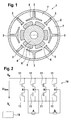
- FIG. 1 is a cross section through an electrical machine in the form of a synchronous motor 1 is shown schematically.
- the synchronous motor 1 has a stator arrangement 2 with eight stator teeth 3.
- the stator assembly 2 is arranged annularly and concentrically about a rotation axis of a rotor 4.
- the stator assembly 2 has in the interior a likewise concentric around the axis of rotation recess.
- the rotor has six rotor poles 5, which are formed by means of permanent magnets 6.
- the rotor 4 is arranged rotatably about the rotation axis in the recess of the stator assembly 2, so that the rotor poles 5 at a rotation of the rotor 4 at inner ends of the stator teeth 3 pass.
- the rotor 4 can advantageously be constructed with three ferromagnetic magnet shells each magnetized in two poles or with a ring of plastic-bonded NdFeB.
- Stator coils 7 are arranged in the form of a follower pole arrangement on the stator teeth 3, ie only every second stator tooth 3 is provided with a stator coil 7 and has a widened tooth head 8 as an inner end compared to unwound stator coils 3.
- the tooth head 8 serves on the one hand for holding the stator coil 7 on the respective stator tooth 3 and on the other hand for widening the region of the magnetic flux generated by the stator coil 7 and directed onto the rotor 4.
- 8n 1, 2, 3, ..., n
- These topologies have the advantage that by selecting the number of stator teeth 3 and by choosing a follower tooth arrangement, the strands formed by the stator coils 7, each associated with a phase are magnetically decoupled, as they magnetize in relation to an electrical rotor position perpendicular axes and additionally separated by auxiliary teeth, which form a magnetic conclusion.
- the invention is applicable to all two-phase synchronous motors in which the stator coils 7 are as magnetic as possible decoupled.
- FIG. 2 a driver circuit 10 for driving circuit of the two-phase bipolar synchronous motor 1 is shown.
- the driver circuit 10 has two bipolar H-bridge circuits.
- Each of the H-bridge circuits comprises two series circuits of power semiconductor switches 11.
- Each of the series circuits has a first power semiconductor switch 11 connected to a first terminal having a high supply potential V H and a second terminal to an output node K.
- each of the series circuits has a second power semiconductor switch 12, which is connected with a first terminal to the output node K and to a second terminal with a low supply potential V L. Between the high supply potential V H and the low supply potential V L is the supply voltage U verse .
- a string comprises one or more stator coils 7 which are connected in a suitable manner for the common energization, i. serial, parallel or a combination of serial and parallel interconnection.
- driver circuit 10 With the help of in FIG. 2 shown driver circuit 10, the strands A and B can be controlled independently, so that they can be energized both individually and simultaneously in any polarity.
- the individual power semiconductor switches 11 are controlled by a control unit 15, so that, depending on the selected switching states of the individual power semiconductor switch 11 of the H-bridge circuit, a positive supply voltage, the negative supply voltage or 0V is applied.
- a pulse width modulation method depending on a duty cycle, an effective voltage can be applied as a control variable to the respective string A, B, which lies between the positive supply voltage U verse and the negative supply voltage -U verse .
- the pulse width modulation method provides a periodic control in which during a first time window, the positive supply voltage (or the negative supply voltage) and during a second time window as voltage 0V output via the output node K of one of the H-bridge circuits.
- the first time window and the second time window define a constant drive period, the duty cycle corresponding to the ratio of the time duration of the first time window to the duration of the drive period.
- the rotor position is detected by a permanent, regular or at predetermined times measuring the characteristic strand inductances, which vary depending on the rotor position. That By assigning a measured phase inductance, the electrical rotor position can be determined by recalculation, readout of a map or the like.
- the characteristic strand inductances are determined by superimposing measuring pulses having a predefined time length (measuring pulse time window) on the driving phase voltages and measuring edge steepnesses as indications of rise times and fall times of a resulting electrical variable.
- An indication of the rise time of the resulting electrical quantity can be measured, for example, by subjecting the edge of the resulting electrical quantity caused by the measurement pulse to threshold comparisons. For example, as an indication of the rise time the Duration of exceeding a first to exceeding a second threshold are measured. Alternatively, a fall time of an edge may also be measured as the time duration of falling below a first threshold to below a second threshold value. From the information on the rise times or the fall times can be determined by a suitable predetermined strand inductance function, for example in the form of a map, an indication of a strand inductance.
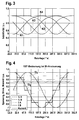
- the four waveforms of the inductance data respectively correspond to inductance curves for a pulse of positive voltage on the string A (K1), a pulse of positive voltage on the string B (K2), a pulse of negative voltage strand A (K3) and a pulse of negative voltage on strand B (K4).
- the measured inductance reaches a minimum of approximately 0.5 of the real (unsaturated) inductance for a given electrical rotor position.
- This rotor position corresponds to a rotor position in which the magnetic flux in the respective stator coil 7 reaches a saturation, whereby the inductance of the relevant stator coil or the relevant strand depends.
- the impressing of a current pulse for determining the rotor position can lead to a disturbance of the torque generation, if the current pulse occurs simultaneously with a current supply of the stator coil for generating a torque.
- torque ripple may increase in this case.
- the measurement of the inductance can be impaired by the energization of the stator coil 7 in particular in a change in the current flow during the measurement.
- FIG. 4 is a diagram illustrating the waveforms of the phase currents and the phase voltages and the resulting torque is shown.
- the diagram shows an example of an energization, in which the phase current is shown with a block length of 135 ° electrical rotor position. That is, during a period of time in which the rotor moves over an electrical rotor position of 180 °, a voltage is applied only during a time window in which the rotor moves in a range of 135 °. In other words, no current is applied to the stator coil during a rotation of the rotor over a rotation angle range of 45 ° electrical rotor position.
- the loss of torque resulting from the reduction in the time length of the current block is compensated for by placing within the current block in the region of the rotor position of 180 °, e.g. in the time center of the current block, the voltage, i. the current amplitude is increased.
- the increase is designed to compensate for the loss of torque due to the non-energization in the range of 45 ° electrical rotor position.
- the voltage pulses are adapted to the sinusoidal current profile. As a result, a small torque ripple can be achieved and at the same time energization gaps can be created in which test pulses for rotor position determination can be discontinued without influencing the activation of the synchronous motor 1.
- the corresponding strand is not energized and instead increased during a time window in the middle of the Bestromungsblocks the current, so that more torque is formed there.
- the measuring impulse for rotor position determination is not or only insignificantly affected by the current in the other strand.
- the rotor position can even be resolved into more than four, for example eight, areas. For determining four ranges of electric rotor position, it is sufficient to determine whether an inductance measured with a certain measurement pulse on a particular string is smaller than a limit value to be determined. For determining more than four, in particular eight ranges of electric rotor position, it must be stated that Whether at least two inductance indications measured with one respective measuring pulse on one or more specific strings and with the same or different polarities are in each case smaller than one or more limit values to be defined. Thus, intermediate positions can be detected to resolve the rotor position finer.
- the inductance curve for different test pulses is shown.
- the electrical commutation ie the driving with corresponding phase currents in predetermined time windows can be determined by threshold value comparisons of the measured normalized inductances.
- a phase current of 0 V is applied to the strand A as a modulation until the inductance determined with the aid of a first of the measuring pulses of positive polarity (curve K1) exceeds a threshold value S.
- the threshold value S is exceeded by the inductance detected by the first measuring pulse at an electrical rotor position of 22.5 °.
- a current with a first positive current value is applied, ie from an electrical rotor position of 22.5 °. Furthermore, the inductance is measured by means of a second measuring pulse having a negative polarity.
- the threshold value S is undershot by the inductance measured using the second measuring pulse (curve K2), the phase current of the strand A is again set to 0 A.
- the phase current of the strand A is set to a second negative current value when the inductance (curve K2) measured by the second measuring pulse exceeds the threshold value S. If the inductance (curve K1) measured by the first measuring pulse falls below the threshold value S, then the phase current is set to 0A. That is, as long as either the inductance measured by the first measuring pulse or the second measuring pulse falls below the threshold value, a phase current of 0 A is applied.
- the elevation of the phase current in the direction of positive currents or in the direction of negative currents in the middle of the respective current block takes place as long as a measured with a third measuring pulse on the second strand B with positive polarity inductance (curve K3) or with a fourth measuring pulse on the second strand B with negative polarity measured inductance (curve K4) below the threshold value S.
- FIG. 5 Another example is shown with a current supply of the strands with a block length of a range of 90 ° electrical rotor position.
- energization of a first strand A occurs at an electrical rotor position between 45 ° and 135 ° in accordance with a current block of positive polarity and between 225 ° and 315 ° with a current block of negative polarity.
- current is applied between 0 ° and 45 ° and between 315 ° and 360 ° with a current block of positive polarity and between 135 ° and 225 ° with a current block of negative polarity.
- no voltage or no current is applied to the strands A, B.
- the other areas of electrical rotor position of the strands, in which no energization of the respective strand takes place, are thus suitable for applying a measuring pulse for determining the rotor position in the respective strand.
- a measuring pulse for determining the rotor position in the respective strand.
- the times for measuring pulses in which the torque-forming current is exposed can be significantly reduced compared to the known methods since the torque-forming method provides time windows in which one or the other branch is not energized, wherein in the time windows, in which no energization is performed, measurements are carried out to the rotor position.
- the advantage of the method described above is that it can also be used when the synchronous machine is at a standstill. Due to the magnetic decoupling of the strands A and B, the inductance influence is isolated without measuring the influences of the other strands and the measuring impulses can be applied simultaneously, whereby the time required to apply the measuring impulses can be reduced. For this purpose, the test pulses can be introduced into the Bestromungslücken, in which no torque is generated anyway.
- the relative difference of the inductances is small. Even with a triangular circuit, one strand with saturation in the stator tooth and two strands without saturation in the stator tooth would always be measured together. The effect to be evaluated is only sufficiently large for reliable detection if the additional inductance as a function of the rotor position is added by the reluctance difference between the follower pole and the magnetic pole.
Applications Claiming Priority (2)
| Application Number | Priority Date | Filing Date | Title |
|---|---|---|---|
| DE102009029155A DE102009029155A1 (de) | 2009-09-03 | 2009-09-03 | Verfahren und Vorrichtung zur Bestimmung einer Rotorlage einer Synchronmaschine |
| PCT/EP2010/060192 WO2011026681A2 (de) | 2009-09-03 | 2010-07-15 | Verfahren und vorrichtung zur bestimmung einer rotorlage einer synchronmaschine |
Publications (2)
| Publication Number | Publication Date |
|---|---|
| EP2474090A2 EP2474090A2 (de) | 2012-07-11 |
| EP2474090B1 true EP2474090B1 (de) | 2013-12-11 |
Family
ID=43571005
Family Applications (1)
| Application Number | Title | Priority Date | Filing Date |
|---|---|---|---|
| EP10734110.9A Active EP2474090B1 (de) | 2009-09-03 | 2010-07-15 | Verfahren und vorrichtung zur bestimmung einer rotorlage einer synchronmaschine |
Country Status (6)
| Country | Link |
|---|---|
| US (1) | US8907606B2 (ja) |
| EP (1) | EP2474090B1 (ja) |
| JP (1) | JP5503004B2 (ja) |
| CN (1) | CN102668360B (ja) |
| DE (1) | DE102009029155A1 (ja) |
| WO (1) | WO2011026681A2 (ja) |
Families Citing this family (4)
| Publication number | Priority date | Publication date | Assignee | Title |
|---|---|---|---|---|
| DE102010020215A1 (de) * | 2010-05-12 | 2011-11-17 | Andreas Stihl Ag & Co. Kg | Verfahren zum Betrieb eines elektronisch kommutierten Elektromotors sowie Vorrichtung zur Durchführung des Verfahrens |
| JP2016518103A (ja) * | 2013-05-07 | 2016-06-20 | サノフィ−アベンティス・ドイチュラント・ゲゼルシャフト・ミット・ベシュレンクテル・ハフツング | コイルインダクタンス決定を採用した装置および装置を動作させるための方法 |
| CN103439655B (zh) * | 2013-06-19 | 2016-05-25 | 南京航空航天大学 | 开关磁阻电机位置传感器的带有容错控制的故障诊断方法 |
| CN108459271B (zh) * | 2018-02-07 | 2021-01-15 | 福建睿能科技股份有限公司 | 两相电机的检测方法及检测装置、具有存储功能的装置 |
Family Cites Families (11)
| Publication number | Priority date | Publication date | Assignee | Title |
|---|---|---|---|---|
| DE2436886C2 (de) * | 1974-07-31 | 1976-05-20 | Berger Gerhard | Selbstanlaufender Synchronmotor und Schrittmotor mit Dauermagnetrotor |
| JPH04359691A (ja) | 1991-03-22 | 1992-12-11 | Fuji Electric Co Ltd | ブラシレスモータの回転子位置検出装置 |
| JP3419157B2 (ja) | 1995-07-20 | 2003-06-23 | 株式会社日立製作所 | モータ駆動方法及びそれを用いた電気機器 |
| JP3381509B2 (ja) * | 1996-02-29 | 2003-03-04 | トヨタ自動車株式会社 | 電気角検出装置および同期モータの駆動装置 |
| JP3393367B2 (ja) | 1998-02-19 | 2003-04-07 | 三菱電機株式会社 | センサレスモータの回転子位置検出装置及びその方法 |
| WO2001073448A1 (fr) * | 2000-03-27 | 2001-10-04 | Mitsubishi Denki Kabushiki Kaisha | Capteur concu pour detecter l'etat de rotation d'une machine synchrone et procede de detection de l'etat de rotation d'une machine synchrone |
| DE10156243A1 (de) * | 2001-11-15 | 2003-06-05 | Bosch Gmbh Robert | Elektronisch kommutierter Motor |
| DE112004001967A5 (de) * | 2003-11-06 | 2012-03-22 | Continental Teves Ag & Co. Ohg | Verfahren zur Ermittlung der Rotorlage einer Synchronmaschine |
| JP4576857B2 (ja) * | 2004-03-12 | 2010-11-10 | 株式会社富士通ゼネラル | 回転子位置推定方法、モータの制御方法、およびプログラム |
| DE102005015783A1 (de) * | 2005-04-01 | 2006-10-05 | Volkswagen Ag | Vorrichtung und Verfahren zum Betrieb einer elektrischen Antriebsmaschine |
| JP4818176B2 (ja) * | 2007-03-26 | 2011-11-16 | 三菱電機株式会社 | モータ駆動制御装置並びに換気扇、液体用ポンプ、冷媒圧縮機、送風機、空気調和機及び冷蔵庫 |
-
2009
- 2009-09-03 DE DE102009029155A patent/DE102009029155A1/de not_active Withdrawn
-
2010
- 2010-07-15 US US13/394,213 patent/US8907606B2/en not_active Expired - Fee Related
- 2010-07-15 WO PCT/EP2010/060192 patent/WO2011026681A2/de active Application Filing
- 2010-07-15 JP JP2012527257A patent/JP5503004B2/ja active Active
- 2010-07-15 CN CN201080039347.7A patent/CN102668360B/zh active Active
- 2010-07-15 EP EP10734110.9A patent/EP2474090B1/de active Active
Also Published As
| Publication number | Publication date |
|---|---|
| CN102668360A (zh) | 2012-09-12 |
| JP2013504290A (ja) | 2013-02-04 |
| EP2474090A2 (de) | 2012-07-11 |
| CN102668360B (zh) | 2015-03-18 |
| WO2011026681A3 (de) | 2012-05-24 |
| US8907606B2 (en) | 2014-12-09 |
| WO2011026681A2 (de) | 2011-03-10 |
| JP5503004B2 (ja) | 2014-05-28 |
| US20120223665A1 (en) | 2012-09-06 |
| DE102009029155A1 (de) | 2011-03-17 |
Similar Documents
| Publication | Publication Date | Title |
|---|---|---|
| EP1961107B1 (de) | Vorrichtung und verfahren zur ermittlung der drehlage des rotors einer elektrischen maschine | |
| EP2875579B1 (de) | Verfahren zur bestimmung der rotorlage eines elektronisch kommutierten mehrphasigen gleichstrommotors | |
| WO1992019038A1 (de) | Verfahren und schaltungsanordnungen zur bestimmung maschinenbezogener elektromagnetischer und mechanischer zustandsgrössen an über umrichter gespeisten elektrodydynamischen drehfeldmaschinen | |
| EP2047585B1 (de) | Synchronmotor, geberloses motorsystem, sowie ein verfahren zum betreiben eines geberlosen motorsystems mit einem synchronmotor | |
| EP2332249A1 (de) | Bestimmung des rotorwinkels einer synchronmaschine im stillstand mit hilfe von iterativen testpulsen | |
| WO2016128468A1 (de) | Verfahren zum betreiben eines bürstenlosen gleichstrommotors | |
| EP1514342B1 (de) | Verfahren und schaltungsanordnung zum betreiben von schrittmotoren | |
| DE102009011674A1 (de) | Verfahren und Vorrichtung zum Betreiben einer elektrischen Maschine | |
| DE102012013652A1 (de) | Verfahren und Vorrichtung zur Positionsbestimmung eines bürstenlosen Elektroantriebs | |
| EP2474090B1 (de) | Verfahren und vorrichtung zur bestimmung einer rotorlage einer synchronmaschine | |
| DE102006038162A1 (de) | Elektromotor mit Messsystem für Position oder Bewegung | |
| EP0418712B1 (de) | Positionssensor | |
| EP1856792B1 (de) | Rotorlagendetektion | |
| EP0670627B1 (de) | Verfahren für den Anlauf und die Kommutierung bei Synchronmaschinen | |
| DE102016123715A1 (de) | Ansteuervorrichtung für einen mehrphasigen Motor und Verfahren zum Ansteuern eines mehrphasigen Motors | |
| EP3297153B1 (de) | Verfahren und vorrichtung zum bestimmen einer läuferlage eines läufers einer elektronisch kommutierten elektrischen maschine | |
| WO2018095482A1 (de) | Verfahren und schaltungsanordnung zur ermittlung der stellung eines rotors eines elektromotors | |
| EP4016835A1 (de) | Verfahren zur bestimmung der winkellage des rotors eines von einem wechselrichter gespeisten synchronmotors und eine vorrichtung zur durchführung des verfahrens | |
| EP3568910A1 (de) | Verfahren zur bestimmung der drehwinkelposition des rotors einer mehrphasigen elektrischen maschine | |
| EP3549254B1 (de) | Vorrichtung und verfahren zur bestimmung der rotorposition | |
| DE4108630C2 (de) | Tachogenerator | |
| DE102014109170A1 (de) | Verfahren zum Betrieb eines sensorlosen Elektromotors und Motoransteuerungsvorrichtung | |
| DE102013218122A1 (de) | Elektronisch kommutierte elektrische Maschine sowie Verfahren zum Betreiben einer elektrischen Maschine | |
| EP4298722A1 (de) | Verfahren und vorrichtung zur identifikation der anisotropie einer elektrischen drehfeldmaschine | |
| WO2013164093A2 (de) | Verfahren und vorrichtung zur positionierung eines bürstenlosen elektroantriebs |
Legal Events
| Date | Code | Title | Description |
|---|---|---|---|
| PUAI | Public reference made under article 153(3) epc to a published international application that has entered the european phase |
Free format text: ORIGINAL CODE: 0009012 |
|
| AK | Designated contracting states |
Kind code of ref document: A2 Designated state(s): AL AT BE BG CH CY CZ DE DK EE ES FI FR GB GR HR HU IE IS IT LI LT LU LV MC MK MT NL NO PL PT RO SE SI SK SM TR |
|
| AX | Request for extension of the european patent |
Extension state: BA ME RS |
|
| 17P | Request for examination filed |
Effective date: 20121126 |
|
| RBV | Designated contracting states (corrected) |
Designated state(s): AL AT BE BG CH CY CZ DE DK EE ES FI FR GB GR HR HU IE IS IT LI LT LU LV MC MK MT NL NO PL PT RO SE SI SK SM TR |
|
| DAX | Request for extension of the european patent (deleted) | ||
| GRAP | Despatch of communication of intention to grant a patent |
Free format text: ORIGINAL CODE: EPIDOSNIGR1 |
|
| RIC1 | Information provided on ipc code assigned before grant |
Ipc: H02P 25/02 20060101AFI20130826BHEP Ipc: H02P 6/18 20060101ALI20130826BHEP Ipc: G01D 5/20 20060101ALI20130826BHEP |
|
| INTG | Intention to grant announced |
Effective date: 20130912 |
|
| GRAS | Grant fee paid |
Free format text: ORIGINAL CODE: EPIDOSNIGR3 |
|
| GRAA | (expected) grant |
Free format text: ORIGINAL CODE: 0009210 |
|
| AK | Designated contracting states |
Kind code of ref document: B1 Designated state(s): AL AT BE BG CH CY CZ DE DK EE ES FI FR GB GR HR HU IE IS IT LI LT LU LV MC MK MT NL NO PL PT RO SE SI SK SM TR |
|
| REG | Reference to a national code |
Ref country code: GB Ref legal event code: FG4D Free format text: NOT ENGLISH |
|
| REG | Reference to a national code |
Ref country code: CH Ref legal event code: EP |
|
| REG | Reference to a national code |
Ref country code: AT Ref legal event code: REF Ref document number: 645025 Country of ref document: AT Kind code of ref document: T Effective date: 20140115 |
|
| REG | Reference to a national code |
Ref country code: IE Ref legal event code: FG4D Free format text: LANGUAGE OF EP DOCUMENT: GERMAN |
|
| REG | Reference to a national code |
Ref country code: DE Ref legal event code: R096 Ref document number: 502010005632 Country of ref document: DE Effective date: 20140206 |
|
| REG | Reference to a national code |
Ref country code: NL Ref legal event code: VDEP Effective date: 20131211 |
|
| PG25 | Lapsed in a contracting state [announced via postgrant information from national office to epo] |
Ref country code: NO Free format text: LAPSE BECAUSE OF FAILURE TO SUBMIT A TRANSLATION OF THE DESCRIPTION OR TO PAY THE FEE WITHIN THE PRESCRIBED TIME-LIMIT Effective date: 20140311 Ref country code: FI Free format text: LAPSE BECAUSE OF FAILURE TO SUBMIT A TRANSLATION OF THE DESCRIPTION OR TO PAY THE FEE WITHIN THE PRESCRIBED TIME-LIMIT Effective date: 20131211 Ref country code: NL Free format text: LAPSE BECAUSE OF FAILURE TO SUBMIT A TRANSLATION OF THE DESCRIPTION OR TO PAY THE FEE WITHIN THE PRESCRIBED TIME-LIMIT Effective date: 20131211 Ref country code: SE Free format text: LAPSE BECAUSE OF FAILURE TO SUBMIT A TRANSLATION OF THE DESCRIPTION OR TO PAY THE FEE WITHIN THE PRESCRIBED TIME-LIMIT Effective date: 20131211 Ref country code: LT Free format text: LAPSE BECAUSE OF FAILURE TO SUBMIT A TRANSLATION OF THE DESCRIPTION OR TO PAY THE FEE WITHIN THE PRESCRIBED TIME-LIMIT Effective date: 20131211 Ref country code: HR Free format text: LAPSE BECAUSE OF FAILURE TO SUBMIT A TRANSLATION OF THE DESCRIPTION OR TO PAY THE FEE WITHIN THE PRESCRIBED TIME-LIMIT Effective date: 20131211 |
|
| REG | Reference to a national code |
Ref country code: LT Ref legal event code: MG4D |
|
| PG25 | Lapsed in a contracting state [announced via postgrant information from national office to epo] |
Ref country code: CY Free format text: LAPSE BECAUSE OF FAILURE TO SUBMIT A TRANSLATION OF THE DESCRIPTION OR TO PAY THE FEE WITHIN THE PRESCRIBED TIME-LIMIT Effective date: 20131211 Ref country code: LV Free format text: LAPSE BECAUSE OF FAILURE TO SUBMIT A TRANSLATION OF THE DESCRIPTION OR TO PAY THE FEE WITHIN THE PRESCRIBED TIME-LIMIT Effective date: 20131211 |
|
| PG25 | Lapsed in a contracting state [announced via postgrant information from national office to epo] |
Ref country code: EE Free format text: LAPSE BECAUSE OF FAILURE TO SUBMIT A TRANSLATION OF THE DESCRIPTION OR TO PAY THE FEE WITHIN THE PRESCRIBED TIME-LIMIT Effective date: 20131211 Ref country code: IS Free format text: LAPSE BECAUSE OF FAILURE TO SUBMIT A TRANSLATION OF THE DESCRIPTION OR TO PAY THE FEE WITHIN THE PRESCRIBED TIME-LIMIT Effective date: 20140411 |
|
| PG25 | Lapsed in a contracting state [announced via postgrant information from national office to epo] |
Ref country code: PL Free format text: LAPSE BECAUSE OF FAILURE TO SUBMIT A TRANSLATION OF THE DESCRIPTION OR TO PAY THE FEE WITHIN THE PRESCRIBED TIME-LIMIT Effective date: 20131211 Ref country code: RO Free format text: LAPSE BECAUSE OF FAILURE TO SUBMIT A TRANSLATION OF THE DESCRIPTION OR TO PAY THE FEE WITHIN THE PRESCRIBED TIME-LIMIT Effective date: 20131211 Ref country code: SK Free format text: LAPSE BECAUSE OF FAILURE TO SUBMIT A TRANSLATION OF THE DESCRIPTION OR TO PAY THE FEE WITHIN THE PRESCRIBED TIME-LIMIT Effective date: 20131211 Ref country code: PT Free format text: LAPSE BECAUSE OF FAILURE TO SUBMIT A TRANSLATION OF THE DESCRIPTION OR TO PAY THE FEE WITHIN THE PRESCRIBED TIME-LIMIT Effective date: 20140411 Ref country code: CZ Free format text: LAPSE BECAUSE OF FAILURE TO SUBMIT A TRANSLATION OF THE DESCRIPTION OR TO PAY THE FEE WITHIN THE PRESCRIBED TIME-LIMIT Effective date: 20131211 Ref country code: ES Free format text: LAPSE BECAUSE OF FAILURE TO SUBMIT A TRANSLATION OF THE DESCRIPTION OR TO PAY THE FEE WITHIN THE PRESCRIBED TIME-LIMIT Effective date: 20131211 |
|
| REG | Reference to a national code |
Ref country code: DE Ref legal event code: R097 Ref document number: 502010005632 Country of ref document: DE |
|
| PLBE | No opposition filed within time limit |
Free format text: ORIGINAL CODE: 0009261 |
|
| STAA | Information on the status of an ep patent application or granted ep patent |
Free format text: STATUS: NO OPPOSITION FILED WITHIN TIME LIMIT |
|
| PG25 | Lapsed in a contracting state [announced via postgrant information from national office to epo] |
Ref country code: DK Free format text: LAPSE BECAUSE OF FAILURE TO SUBMIT A TRANSLATION OF THE DESCRIPTION OR TO PAY THE FEE WITHIN THE PRESCRIBED TIME-LIMIT Effective date: 20131211 |
|
| 26N | No opposition filed |
Effective date: 20140912 |
|
| REG | Reference to a national code |
Ref country code: DE Ref legal event code: R097 Ref document number: 502010005632 Country of ref document: DE Effective date: 20140912 |
|
| PG25 | Lapsed in a contracting state [announced via postgrant information from national office to epo] |
Ref country code: LU Free format text: LAPSE BECAUSE OF FAILURE TO SUBMIT A TRANSLATION OF THE DESCRIPTION OR TO PAY THE FEE WITHIN THE PRESCRIBED TIME-LIMIT Effective date: 20140715 Ref country code: SI Free format text: LAPSE BECAUSE OF FAILURE TO SUBMIT A TRANSLATION OF THE DESCRIPTION OR TO PAY THE FEE WITHIN THE PRESCRIBED TIME-LIMIT Effective date: 20131211 |
|
| REG | Reference to a national code |
Ref country code: CH Ref legal event code: PL |
|
| GBPC | Gb: european patent ceased through non-payment of renewal fee |
Effective date: 20140715 |
|
| REG | Reference to a national code |
Ref country code: IE Ref legal event code: MM4A |
|
| PG25 | Lapsed in a contracting state [announced via postgrant information from national office to epo] |
Ref country code: CH Free format text: LAPSE BECAUSE OF NON-PAYMENT OF DUE FEES Effective date: 20140731 Ref country code: LI Free format text: LAPSE BECAUSE OF NON-PAYMENT OF DUE FEES Effective date: 20140731 |
|
| PG25 | Lapsed in a contracting state [announced via postgrant information from national office to epo] |
Ref country code: GB Free format text: LAPSE BECAUSE OF NON-PAYMENT OF DUE FEES Effective date: 20140715 |
|
| PG25 | Lapsed in a contracting state [announced via postgrant information from national office to epo] |
Ref country code: IE Free format text: LAPSE BECAUSE OF NON-PAYMENT OF DUE FEES Effective date: 20140715 |
|
| PG25 | Lapsed in a contracting state [announced via postgrant information from national office to epo] |
Ref country code: MC Free format text: LAPSE BECAUSE OF FAILURE TO SUBMIT A TRANSLATION OF THE DESCRIPTION OR TO PAY THE FEE WITHIN THE PRESCRIBED TIME-LIMIT Effective date: 20131211 Ref country code: SM Free format text: LAPSE BECAUSE OF FAILURE TO SUBMIT A TRANSLATION OF THE DESCRIPTION OR TO PAY THE FEE WITHIN THE PRESCRIBED TIME-LIMIT Effective date: 20131211 |
|
| PG25 | Lapsed in a contracting state [announced via postgrant information from national office to epo] |
Ref country code: GR Free format text: LAPSE BECAUSE OF FAILURE TO SUBMIT A TRANSLATION OF THE DESCRIPTION OR TO PAY THE FEE WITHIN THE PRESCRIBED TIME-LIMIT Effective date: 20140312 Ref country code: BG Free format text: LAPSE BECAUSE OF FAILURE TO SUBMIT A TRANSLATION OF THE DESCRIPTION OR TO PAY THE FEE WITHIN THE PRESCRIBED TIME-LIMIT Effective date: 20131211 Ref country code: MT Free format text: LAPSE BECAUSE OF FAILURE TO SUBMIT A TRANSLATION OF THE DESCRIPTION OR TO PAY THE FEE WITHIN THE PRESCRIBED TIME-LIMIT Effective date: 20131211 |
|
| REG | Reference to a national code |
Ref country code: FR Ref legal event code: PLFP Year of fee payment: 7 |
|
| PG25 | Lapsed in a contracting state [announced via postgrant information from national office to epo] |
Ref country code: HU Free format text: LAPSE BECAUSE OF FAILURE TO SUBMIT A TRANSLATION OF THE DESCRIPTION OR TO PAY THE FEE WITHIN THE PRESCRIBED TIME-LIMIT; INVALID AB INITIO Effective date: 20100715 Ref country code: BE Free format text: LAPSE BECAUSE OF FAILURE TO SUBMIT A TRANSLATION OF THE DESCRIPTION OR TO PAY THE FEE WITHIN THE PRESCRIBED TIME-LIMIT Effective date: 20140731 Ref country code: TR Free format text: LAPSE BECAUSE OF FAILURE TO SUBMIT A TRANSLATION OF THE DESCRIPTION OR TO PAY THE FEE WITHIN THE PRESCRIBED TIME-LIMIT Effective date: 20131211 |
|
| REG | Reference to a national code |
Ref country code: AT Ref legal event code: MM01 Ref document number: 645025 Country of ref document: AT Kind code of ref document: T Effective date: 20150715 |
|
| PG25 | Lapsed in a contracting state [announced via postgrant information from national office to epo] |
Ref country code: AT Free format text: LAPSE BECAUSE OF NON-PAYMENT OF DUE FEES Effective date: 20150715 |
|
| REG | Reference to a national code |
Ref country code: FR Ref legal event code: PLFP Year of fee payment: 8 |
|
| PG25 | Lapsed in a contracting state [announced via postgrant information from national office to epo] |
Ref country code: MK Free format text: LAPSE BECAUSE OF FAILURE TO SUBMIT A TRANSLATION OF THE DESCRIPTION OR TO PAY THE FEE WITHIN THE PRESCRIBED TIME-LIMIT Effective date: 20131211 |
|
| REG | Reference to a national code |
Ref country code: FR Ref legal event code: PLFP Year of fee payment: 9 |
|
| PG25 | Lapsed in a contracting state [announced via postgrant information from national office to epo] |
Ref country code: AL Free format text: LAPSE BECAUSE OF FAILURE TO SUBMIT A TRANSLATION OF THE DESCRIPTION OR TO PAY THE FEE WITHIN THE PRESCRIBED TIME-LIMIT Effective date: 20131211 |
|
| PGFP | Annual fee paid to national office [announced via postgrant information from national office to epo] |
Ref country code: IT Payment date: 20220729 Year of fee payment: 13 Ref country code: DE Payment date: 20220927 Year of fee payment: 13 |
|
| PGFP | Annual fee paid to national office [announced via postgrant information from national office to epo] |
Ref country code: FR Payment date: 20220725 Year of fee payment: 13 |
|
| REG | Reference to a national code |
Ref country code: DE Ref legal event code: R119 Ref document number: 502010005632 Country of ref document: DE |
|
| PG25 | Lapsed in a contracting state [announced via postgrant information from national office to epo] |
Ref country code: DE Free format text: LAPSE BECAUSE OF NON-PAYMENT OF DUE FEES Effective date: 20240201 |