EP2472268B1 - Marking or scanning apparatus with a measuring device for measuring the speed of an object and a method of measuring the speed of an object with such a marking or scanning apparatus - Google Patents
Marking or scanning apparatus with a measuring device for measuring the speed of an object and a method of measuring the speed of an object with such a marking or scanning apparatus Download PDFInfo
- Publication number
- EP2472268B1 EP2472268B1 EP10016201A EP10016201A EP2472268B1 EP 2472268 B1 EP2472268 B1 EP 2472268B1 EP 10016201 A EP10016201 A EP 10016201A EP 10016201 A EP10016201 A EP 10016201A EP 2472268 B1 EP2472268 B1 EP 2472268B1
- Authority
- EP
- European Patent Office
- Prior art keywords
- marking
- receiving
- scanning
- fibre
- scanning apparatus
- Prior art date
- Legal status (The legal status is an assumption and is not a legal conclusion. Google has not performed a legal analysis and makes no representation as to the accuracy of the status listed.)
- Not-in-force
Links
Images


Classifications
-
- G—PHYSICS
- G01—MEASURING; TESTING
- G01P—MEASURING LINEAR OR ANGULAR SPEED, ACCELERATION, DECELERATION, OR SHOCK; INDICATING PRESENCE, ABSENCE, OR DIRECTION, OF MOVEMENT
- G01P3/00—Measuring linear or angular speed; Measuring differences of linear or angular speeds
- G01P3/36—Devices characterised by the use of optical means, e.g. using infrared, visible, or ultraviolet light
-
- B—PERFORMING OPERATIONS; TRANSPORTING
- B41—PRINTING; LINING MACHINES; TYPEWRITERS; STAMPS
- B41J—TYPEWRITERS; SELECTIVE PRINTING MECHANISMS, i.e. MECHANISMS PRINTING OTHERWISE THAN FROM A FORME; CORRECTION OF TYPOGRAPHICAL ERRORS
- B41J2/00—Typewriters or selective printing mechanisms characterised by the printing or marking process for which they are designed
- B41J2/435—Typewriters or selective printing mechanisms characterised by the printing or marking process for which they are designed characterised by selective application of radiation to a printing material or impression-transfer material
- B41J2/447—Typewriters or selective printing mechanisms characterised by the printing or marking process for which they are designed characterised by selective application of radiation to a printing material or impression-transfer material using arrays of radiation sources
- B41J2/46—Typewriters or selective printing mechanisms characterised by the printing or marking process for which they are designed characterised by selective application of radiation to a printing material or impression-transfer material using arrays of radiation sources characterised by using glass fibres
-
- G—PHYSICS
- G01—MEASURING; TESTING
- G01P—MEASURING LINEAR OR ANGULAR SPEED, ACCELERATION, DECELERATION, OR SHOCK; INDICATING PRESENCE, ABSENCE, OR DIRECTION, OF MOVEMENT
- G01P1/00—Details of instruments
- G01P1/02—Housings
- G01P1/026—Housings for speed measuring devices, e.g. pulse generator
-
- G—PHYSICS
- G01—MEASURING; TESTING
- G01P—MEASURING LINEAR OR ANGULAR SPEED, ACCELERATION, DECELERATION, OR SHOCK; INDICATING PRESENCE, ABSENCE, OR DIRECTION, OF MOVEMENT
- G01P3/00—Measuring linear or angular speed; Measuring differences of linear or angular speeds
- G01P3/64—Devices characterised by the determination of the time taken to traverse a fixed distance
- G01P3/68—Devices characterised by the determination of the time taken to traverse a fixed distance using optical means, i.e. using infrared, visible, or ultraviolet light
-
- G—PHYSICS
- G01—MEASURING; TESTING
- G01S—RADIO DIRECTION-FINDING; RADIO NAVIGATION; DETERMINING DISTANCE OR VELOCITY BY USE OF RADIO WAVES; LOCATING OR PRESENCE-DETECTING BY USE OF THE REFLECTION OR RERADIATION OF RADIO WAVES; ANALOGOUS ARRANGEMENTS USING OTHER WAVES
- G01S17/00—Systems using the reflection or reradiation of electromagnetic waves other than radio waves, e.g. lidar systems
- G01S17/02—Systems using the reflection of electromagnetic waves other than radio waves
- G01S17/50—Systems of measurement based on relative movement of target
- G01S17/58—Velocity or trajectory determination systems; Sense-of-movement determination systems
-
- G—PHYSICS
- G01—MEASURING; TESTING
- G01S—RADIO DIRECTION-FINDING; RADIO NAVIGATION; DETERMINING DISTANCE OR VELOCITY BY USE OF RADIO WAVES; LOCATING OR PRESENCE-DETECTING BY USE OF THE REFLECTION OR RERADIATION OF RADIO WAVES; ANALOGOUS ARRANGEMENTS USING OTHER WAVES
- G01S7/00—Details of systems according to groups G01S13/00, G01S15/00, G01S17/00
- G01S7/48—Details of systems according to groups G01S13/00, G01S15/00, G01S17/00 of systems according to group G01S17/00
- G01S7/481—Constructional features, e.g. arrangements of optical elements
- G01S7/4818—Constructional features, e.g. arrangements of optical elements using optical fibres
Definitions
- the present invention relates to a marking and/or scanning apparatus comprising measuring device for measuring the speed of an object according to claim 1.
- the invention further relates to a method for measuring the speed of an object according to claim 13.
- Measuring devices for measuring the speed of an object are well known in the art.
- the rotating speed of a driveshaft, which drives the object is measured and the determined value is converted to the speed of the object.
- a drawback of this principle of measurement is a limited accuracy, if for example the object is placed on a conveyor belt and there is a slip between the conveyor belt and the driveshaft or between the object and the conveyor belt.
- Another example of a measuring principle is the use of photodetectors or photosensors to determine the speed of an object based on the time the object needs to cover a certain distance.
- WO 85/05187 describes an apparatus for optical measurement of movement of an object including means adapted to transmit light onto the surface of the object and means adapted to receive light reflected by this surface. An electric signal is produced corresponding to light received from each of a number of mutually spaced light-receiving elements, and a signal processing circuit is provided for determining the relative timeshift of two electric signals, this timeshift constituting a measurement of the velocity of the object.
- DE 38 26 113 A1 discloses a device for determining the velocity of moving particles, in particular in a multiple-phase-flow.
- US 6,855,921 B1 discloses a portable speed measurement apparatus for determining and displaying speed characteristics of a body passing through a target zone.
- the object is solved according to the invention with a marking and/or scanning apparatus comprising a measuring device for measuring the speed of an object having the features of claim 1 and a method for measuring the speed of an object having the features of claim 13.
- the inventive measuring device comprises a transmitter having a transmitting fibre for transmitting a light to the object, a receiver having a first receiving fibre and a second receiving fibre for receiving light reflected from the object, wherein the reflected light received by the first receiving fibre forms a first light signal and a reflected light received by the second receiving fibre forms a second light signal, and a sensor and signal processor means for detecting the first and second light signals, for determining a time shift between the first light signal and the second light signal and for converting the determined time shift to a speed value of the object.
- the transmitting fibre, the first receiving fibre and the second receiving fibre are arranged in a common ferrule.
- light is transmitted to the object through a transmitting fibre, the light is at least partly reflected or scattered by the object and received by a first receiving fibre and a second receiving fibre, wherein the reflected light received the first receiving fibre forms a first light signal and the reflected light received by the second receiving fibre forms a second light signal and wherein the transmitting fibre, the first receiving fibre and the second receiving fibre are arranged in a common ferrule, the first and second light signals are detected and a time shift between the first light signal and the second light signal is determined and converted to a speed value of the object.
- One basic idea of the invention is to provide a speed measuring device having a plurality of optical fibres arranged in a common housing called a ferrule.
- the ends of the fibres are arranged in the ferrule.
- the ferrule is adapted to tightly hold the fibre ends arranged therein, that is, to tightly hold the ends of at least one transmitting fibre and at least two receiving fibres.
- the measuring device is based on the principle of determining the speed of the object with an optical sensor element such as a photosensor or photodetector arranged in the sensor and signal processor means.
- the photosensor or photodetector may be a photodiode, a phototransistor, or a photoresistor.
- Light is transmitted onto a surface of the object through a transmitting fibre, reflected or scattered by the surface of the object and received by two receiving fibres.
- a lighting element such as a light emitting diode (LED) is arranged to emit a light signal.
- the light emitted by the lighting element and transmitted through the transmitting fibre may be visible light, infrared light or any other type of electromagnetic radiation.
- the light is detected by one or more sensor elements such as photodiodes arranged at an end of the receiving fibres opposed to the surface of the object.
- the sensor and signal processor means comprises at least one sensor element connected to the first receiving fibre and the second receiving fibre, the sensor element being configured to detect varying light power levels due to a roughness and/or structure of a surface of the object and the sensor and signal processor means is configured to convert a phase shift of the varying light power levels to the speed value of the object.
- an inherent roughness and/or structure in the surface of the object leads to varying light power levels, which are detectable by a sensor element.
- the varying light power levels are in particular detectable at the ends of both the first and second receiving fibres. If the object is moved along an advance direction, which may also be called a product movement direction, there will be a time or phase shift between the varying light power levels received by the first receiving fibre and the second receiving fibre. This time or phase shift is converted to the speed value of the object.
- the object may be a one-colored object, for example a piece of paper or an object made of plastic such as a cap of a bottle.
- the object can have a planar surface with a micro-structure of roughness or have a structured surface such as a profiling, as for example the profiled surface of a plastic cap of a bottle.
- the sensor element being adapted and configured to detect rather small differences in the light power or light intensity, it is in particular not necessary to provide a special speed measuring marking on the object.
- the presence of a roughness and/or structure on the object is sufficient for determining the speed of the object based on the detected phase or time shift of the light power levels.
- an optical element in particular at least one optical lens, is provided in front of the fibre ends, in particular between the fibres ends and the object.
- the optical element is in particular configured to focus the light emitted by the transmitting fibre and reflected from the object.
- the ferrule has a body having a substantially cylindrical outer shape with a profiling for being inserted into a receiving hole of a marking and/or scanning apparatus in a defined angular position.
- the ferrule may in particular be keyed, so that it may be placed in a receiving hole having a corresponding keying in a defined position. It is therefore preferred that the ferrule has a keyed body for being inserted into a receiving hole of a marking and/or scanning apparatus in a defined angular position. It is particularly preferred that the ferrule has a keying such as a groove or tongue extending along a longitudinal axis of the ferrule.
- the ferrule has a body with a polygonal cross-section for being inserted into a receiving hole of a marking and/or scanning apparatus in a defined angular position.
- the polygonal cross-section may in particular be a triangle or a rectangle.
- the receiving hole may have a corresponding cross-section according to the cross-section of the ferrule.
- the ferrule has a molded body.
- the technology of molding is an advantageous manufacturing technology in order to provide a robust body with precise predetermined dimensions.
- the invention relates to a marking and/or scanning apparatus for marking and/or scanning an object.
- a known marking and/or scanning apparatus for marking and/or scanning an object comprises a marking and/or scanning head having a plurality of receiving spaces for individual marking and/or scanning devices and a driving mechanism for providing a relative movement of the object relative to the marking and/or scanning head in an advance direction during a marking and/or scanning operation.
- the object is usually placed on a conveyor belt, which is driven by a driveshaft.
- the speed of the object is measured based on the rotating speed of the driveshaft.
- a drawback of this measuring principle is that a slip between the driveshaft and the conveyor belt adversely affects the preciseness of the measuring result.
- the marking and/or scanning apparatus comprises a measuring device as defined in this document which is arranged in at least one of the receiving spaces of the marking and/or scanning head for measuring the speed of the object in the advance direction.
- a basic of idea of the invention is to provide an integrated marking and/or scanning apparatus with a measuring device.
- the inventive marking and/or scanning apparatus allows for a very precise determination of the speed of the object to be marked or scanned relative to the marking and/or scanning devices arranged in the marking and/or scanning head.
- the marking and/or scanning apparatus comprises a plurality of marking and/or scanning devices in a ferrule shape.
- the combination of marking and/or scanning devices including ferrules and a measuring device also having a ferrule provides a very flexible marking and/or scanning apparatus.
- a marking and/or scanning devices includes a ferrule and one or more fibre ends coupled to the ferrule.
- the fibres may be coupled to a lighting element, for example a laser for marking and/or engraving the object by means of a laser beam.
- the fibres may be coupled to a sensor element for detecting light received through the fibre.
- the shape of the ferrule of the measuring device corresponds to the shape of the ferrule of at least one marking and/or scanning device, so that the measuring device and the marking and/or scanning device may be exchanged.
- the ferrules of the marking and/or scanning devices and the ferrule of the measuring device have corresponding connector sections for being variably connected to or engaged with the receiving spaces of the marking and/or scanning head. That is, the ferrules of the marking and/or scanning devices and the ferrule of the measuring device have equal or corresponding connector sections, so that a receiving space of the marking and/or scanning head may be selectively equipped with a marking and/or scanning device or the measuring device according to the invention.
- the receiving spaces of the marking and/or scanning head are receiving holes formed in a receiving plate.
- the receiving holes may in particular be through-holes.
- the ferrules of the marking and/or scanning devices and the ferrule of the measuring device may be inserted into the receiving holes and thereby coupled to the receiving plate.
- the receiving spaces are arranged in a two-dimensional array having a plurality of rows extending transversely to the advance direction, wherein the marking and/or scanning devices are arranged in at least one first row and the measuring device is arranged in a second row.
- the plurality of rows allows at least one row to be exclusively used for the marking and/or scanning devices, so that the complete width of the marking and/or scanning head in the transverse direction may be used for marking and/or scanning the object.
- the marking and/or scanning head provides at least one additional row for arranging the measuring device.
- the array of receiving spaces is tilted with regard to the advance direction, wherein the receiving spaces of a successive row are offset with regard to the receiving spaces of preceding row in a direction perpendicular to the advance direction.
- the resolution of the marking and/or scanning apparatus may be enhanced.
- the array of receiving spaces comprises a plurality of rows and a plurality of columns, in which the receiving spaces are arranged, wherein the rows and the columns extend perpendicularly to each other.
- Such an array may also be called a rectangular pattern of the receiving spaces.
- the array is slightly inclined so that the receiving spaces of a successive row are offset with regard to the receiving spaces of a preceding row.
- the amount of offset is preferably smaller than a pitch between the receiving spaces of one row, wherein the pitch is defined as the distance between two adjacent or adjoining receiving spaces of one row.
- the marking and/or scanning head is rotatable about an axis perpendicular to the advance direction, in particular perpendicular to a surface of the object to be marked and/or scanned.
- a measuring means is provided for determining a tilting angle of the marking and/or scanning head and that an output value of the measuring means is provided at the sensor and signal processor means.
- the sensor and signal processor means may then determine the speed of the object relative to the tilted marking and/or scanning head based on the time shift between the light signals and the tilting angle of the head.
- the fist receiving fibre and the second receiving fibre are arranged along the advance direction.
- the first receiving fibre and the second receiving fibre should be arranged relative to the advance direction such that there is a predetermined distance between the central points of the first and second receiving fibres in the advance direction.
- first receiving fibre and the second receiving fibre are offset with regard to the advance direction.
- first receiving fibre and the second receiving fibre are aligned in the advance direction.
- the transmitting fibre is preferably arranged between the first receiving fibre and the second receiving fibre.
- the transmitting fibre may be aligned with at least one of the receiving fibres in the advance direction.
- the transmitting fibre can be offset with regard to the first receiving fibre and/or the second receiving fibre in a direction perpendicular to the advance direction.
- the transmitting fibre is centrally arranged between the first and second receiving fibres, that is, a distance between the first receiving fibre and the transmitting fibre is equal to a distance between the second receiving fibre and the transmitting fibre.
- the transmitting fibre and the first and second receiving fibres are arranged in the corners of a triangle.
- Another preferred embodiment of the invention is given by a method for marking and/or scanning an object, in particular with a marking and/or scanning apparatus as described in this document, wherein the object is marked and/or scanned by a plurality of individual marking and/or scanning devices arranged in a common marking and/or scanning head and the object is moved relative to the marking and/or scanning head in an advance direction during a marking and/or scanning operation, wherein a speed of the object in the advance direction is measured with the method as described in this document.
- the object is marked and/or scanned by a plurality of marking and/or scanning devices arranged in a marking and/or scanning head, wherein the speed of the object is determined by a measuring device arranged in the same head.
- the marking and/or scanning devices and the measuring device are arranged in the same head, no relative movement between these components is possible.
- the method therefore provides a very exact determination of the speed of the object to be marked or scanned.
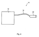
- the principle structure of a marking and/or scanning apparatus 10 is shown in Fig. 4 .
- the marking and/or scanning apparatus 10 comprises a marking and/or scanning head 20 with a plurality of marking and/or scanning devices 40.
- the apparatus 10 further comprises a control and driving unit 12 for controlling the marking and/or scanning devices 40.
- the control and driving unit 12 is connected and the marking and/or scanning head 20 through an umbilical 14.
- the umbilical 14 may have a plurality of fibres arranged therein.
- the marking and/or scanning devices can for example be printing devices for printing an object.
- the printing devices can include ink jet nozzles, laser printing devices or laser engraving devices, which apply a printing with a laser beam directed onto the object.
- the marking and/or scanning apparatus 10 may in particular be a matrix or pixel printer or a matrix or pixel scanner.
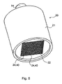
- Fig. 5 shows a general embodiment of a marking and/or scanning head 20, which can in particular be a printing head and/or sensor head.
- the marking and/or scanning head 20 comprises a housing 21, which in the shown embodiment has a cylindrical outer shape.
- the marking and/or scanning head 20 includes a plurality of receiving spaces 24 arranged in a regular rectangular pattern forming a two-dimensional array 22.
- the receiving spaces 24 may be equipped with individual marking and/or scanning devices 40.
- FIG. 6 An empty array 22 of receiving spaces 24 is shown in Fig. 6 .
- the receiving spaces 24 are arranged in rows 30 and columns 32 extending perpendicularly to each other.
- the array 22 of receiving spaces 24 has a rectangular outer shape.
- the marking and/or scanning head 20 includes a receiving plate 28 having a plurality of receiving holes 26 forming the receiving spaces 24.
- the receiving plate 28 may for example be a metal plate, in particular a steel plate.
- the receiving holes 26 each have a substantially circular cross-section and may in particular be through holes.
- the receiving plate 28 comprises an array 22 of receiving spaces 24 arranged in a regular square pattern.
- the shown array 22 comprises 32 times 32 receiving spaces 24.
- a plurality of spare receiving spaces 25 is provided for accommodating spare marking and/or scanning devices.
- the spare receiving spaces 25 are also formed as receiving holes in the receiving plate 28.
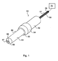
- Fig. 1 schematically shows an embodiment of a measuring device 50 according to the invention.
- the measuring device 50 includes a ferrule 52 with a substantially cylindrical body 53.
- the ferrule 52 can for example include a metal, a ceramic, a plastic material or glass. It is particularly preferred that the ferrule 52 includes steal or zirconia.
- the body 53 of the ferrule 52 includes a connecting portion or a connector section 59 for engaging a receiving space 24 of the marking and/or scanning head 20.
- the connector section 59 has a substantially cylindrical shape for a mating engagement with a cylindrical receiving hole 26 provided in the receiving plate 28 of a marking and/or scanning head 20.
- the body 53 of the ferrule 52 further includes a collar 54 with an abutment surface 55 for contacting a planar surface of the receiving plate 28.
- the measuring device 50 comprises three optical fibres.
- One of the fibres is a transmitting fibre 56 for transmitting light to an object.
- the light can be any kind of electromagnetic radiation such as for example visible light or infrared light.
- the other two fibres are receiving fibres 57, 58 for receiving light transmitted by the transmitting fibre 56 and reflected by the object.
- the transmitting fibre 56 and the receiving fibres 57, 58 are arranged along a longitudinal axis of the ferrule 52. In a cross-section of the ferrule, the transmitting fibre 57 and the receiving fibres 57, 58 are arranged symmetrically to each other in the corners of a triangle.
- the transmitting fibre 56 is connected to a lighting element such as a light emitting diode for transmitting light through the transmitting fibre 56 onto a surface of the object.
- the first and second receiving fibres 57, 58 are connected to a sensor and signal processor means 70 for detecting the light signals received by the receiving fibres 57, 58 and converting a time shift between the light signals into a speed value of the object in a movement or advance direction 16.
- the sensor and signal processor means 70 may in particular comprise one or more sensor elements such as photodiodes for detecting the light signals.
- Fig. 2 illustrates a detector device 80.
- the detector device 80 has fundamentally the same structure as the measuring device 50, except that it has only two fibres instead of the at least three fibres of the measuring device 50.
- one of the two fibres is a transmitting fibre 56 and the other is a receiving fibre 57.
- the detector device 80 may be used for detecting the presence of the object to be marked and/or scanned. To this end, light may be emitted from the transmitting fibre 56. If the object is present, the light will be at least partly reflected by the object and received by the receiving fibre 57. The light received by the receiving fibre 57 may then be detected by a sensor element such as a photodiode coupled to the receiving fibre 57.
- the detector device 80 may be used for verification of the functioning of the measuring device 50.
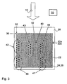
- Fig. 3 shows a receiving plate 28 of a marking and/or scanning head 20, in which the receiving spaces 24 are partly populated with marking and/or scanning devices 40.
- the marking and/or scanning devices 40 include a plurality of marking devices 42, 43, 44 and a plurality of scanning devices 46, 47.
- the marking devices 42, 43, 44 may be of different types.
- the marking devices 42 may be ink jet nozzles
- the marking devices 43 may be CO 2 laser ferrules
- the marking devices 44 may be laser diode ferrules.
- the scanning devices 44 are arranged downstream of the marking devices 42 in the advance direction 16 of the object.
- the advance direction 16 may also be called a product or object movement direction. With the scanning devices 44 a marking applied by the marking devices 42 can be verified.
- a measuring device 50 is arranged in one of the receiving spaces 24. With the measuring device 50 the speed of the object to be marked and/or scanned can be precisely measured.
- the marking head 20 includes a detector device 80, as shown in Fig. 4 , for detecting the presence of the object to be marked and/or scanned.
- the array 22 of receiving spaces may be tilted or rotated with regard to the advance direction 16, so that the receiving spaces 24 of a preceding row 30a are offset with regard to the receiving spaces 24 of a successive row 30b in a transverse direction to the advance direction 16.
- the tilted or rotated array 22 provides an enhanced resolution of the marking and/or scanning being performed by the marking and/or scanning head 20.
Landscapes
- Physics & Mathematics (AREA)
- Engineering & Computer Science (AREA)
- General Physics & Mathematics (AREA)
- Electromagnetism (AREA)
- Computer Networks & Wireless Communication (AREA)
- Remote Sensing (AREA)
- Radar, Positioning & Navigation (AREA)
- General Health & Medical Sciences (AREA)
- Toxicology (AREA)
- Health & Medical Sciences (AREA)
- Power Engineering (AREA)
- Length Measuring Devices By Optical Means (AREA)
- Investigating Materials By The Use Of Optical Means Adapted For Particular Applications (AREA)
- Optical Transform (AREA)
Priority Applications (8)
| Application Number | Priority Date | Filing Date | Title |
|---|---|---|---|
| ES10016201T ES2405982T3 (es) | 2010-12-30 | 2010-12-30 | Aparato de marcado o de barrido con un dispositivo de medición para medir la velocidad de un objeto y procedimiento de medición de la velocidad de un objeto con dicho aparato de marcado o de barrido |
| EP10016201A EP2472268B1 (en) | 2010-12-30 | 2010-12-30 | Marking or scanning apparatus with a measuring device for measuring the speed of an object and a method of measuring the speed of an object with such a marking or scanning apparatus |
| DK10016201.5T DK2472268T3 (da) | 2010-12-30 | 2010-12-30 | Markerings- eller scanningsapparat med en måleindretning til måling af hastigheden af en genstand samt fremgangsmåde til måling af hastigheden af en genstand med et sådant markerings- eller scanningsapparat |
| EA201390512A EA023994B1 (ru) | 2010-12-30 | 2011-12-22 | Аппарат для маркирования объекта, аппарат для сканирования объекта и способ маркирования и сканирования объекта с их использованием |
| BR112013014969A BR112013014969A2 (pt) | 2010-12-30 | 2011-12-22 | aparelho de marcação ou leitura com dispositivo de medição para medir a velocidade de objeto e método de medir a velocidade de objeto com tal aparelho de marcação ou leitura |
| CN201180062337.XA CN103282783B (zh) | 2010-12-30 | 2011-12-22 | 带有用于测量物体速度的测量设备的标记或扫描装置,以及使用该标记或扫描装置测量物体速度的方法 |
| PCT/EP2011/006518 WO2012089323A1 (en) | 2010-12-30 | 2011-12-22 | Marking or scanning apparatus with a measuring device for measuring the speed of an object and a method of measuring the speed of an object with such a marking or scanning apparatus |
| US13/976,814 US8982335B2 (en) | 2010-12-30 | 2011-12-22 | Marking or scanning apparatus with a measuring device for measuring the speed of an object and a method of measuring the speed of an object with such a marking or scanning apparatus |
Applications Claiming Priority (1)
| Application Number | Priority Date | Filing Date | Title |
|---|---|---|---|
| EP10016201A EP2472268B1 (en) | 2010-12-30 | 2010-12-30 | Marking or scanning apparatus with a measuring device for measuring the speed of an object and a method of measuring the speed of an object with such a marking or scanning apparatus |
Publications (2)
| Publication Number | Publication Date |
|---|---|
| EP2472268A1 EP2472268A1 (en) | 2012-07-04 |
| EP2472268B1 true EP2472268B1 (en) | 2013-02-13 |
Family
ID=44026188
Family Applications (1)
| Application Number | Title | Priority Date | Filing Date |
|---|---|---|---|
| EP10016201A Not-in-force EP2472268B1 (en) | 2010-12-30 | 2010-12-30 | Marking or scanning apparatus with a measuring device for measuring the speed of an object and a method of measuring the speed of an object with such a marking or scanning apparatus |
Country Status (8)
| Country | Link |
|---|---|
| US (1) | US8982335B2 (da) |
| EP (1) | EP2472268B1 (da) |
| CN (1) | CN103282783B (da) |
| BR (1) | BR112013014969A2 (da) |
| DK (1) | DK2472268T3 (da) |
| EA (1) | EA023994B1 (da) |
| ES (1) | ES2405982T3 (da) |
| WO (1) | WO2012089323A1 (da) |
Families Citing this family (12)
| Publication number | Priority date | Publication date | Assignee | Title |
|---|---|---|---|---|
| DK2472843T3 (da) | 2010-12-30 | 2019-02-25 | Alltec Angewandte Laserlicht Tech Gesellschaft Mit Beschraenkter Haftung | Fremgangsmåde til styring af et apparat til at udskrive og/eller skanne en genstand |
| EP2471664B1 (en) | 2010-12-30 | 2013-04-24 | ALLTEC Angewandte Laserlicht Technologie Gesellschaft mit beschränkter Haftung | Device for marking and/or scanning an object |
| ES2398780T3 (es) | 2010-12-30 | 2013-03-21 | ALLTEC Angewandte Laserlicht Technologie Gesellschaft mit beschränkter Haftung | Dispositivo de vigilancia y procedimiento de vigilancia de elementos de marcado de una cabeza de marcado |
| DK2471665T3 (da) * | 2010-12-30 | 2013-05-06 | Alltec Angewandte Laserlicht Technologie Gmbh | Markerings- og/eller scanningshoved, -indretning og -fremgangsmåde |
| EP2472842B1 (en) | 2010-12-30 | 2020-03-04 | ALLTEC Angewandte Laserlicht Technologie Gesellschaft mit beschränkter Haftung | Sensor apparatus |
| ES2398134T3 (es) | 2010-12-30 | 2013-03-13 | ALLTEC Angewandte Laserlicht Technologie Gesellschaft mit beschränkter Haftung | Procedimiento para aplicar una marca sobre un objeto y aparato de marcado |
| DK2472268T3 (da) | 2010-12-30 | 2013-03-04 | Alltec Angewandte Laserlicht Technologie Gmbh | Markerings- eller scanningsapparat med en måleindretning til måling af hastigheden af en genstand samt fremgangsmåde til måling af hastigheden af en genstand med et sådant markerings- eller scanningsapparat |
| EP2471658B1 (en) | 2010-12-30 | 2018-10-03 | ALLTEC Angewandte Laserlicht Technologie Gesellschaft mit beschränkter Haftung | Marking apparatus |
| EP2471669B1 (en) | 2010-12-30 | 2013-07-10 | ALLTEC Angewandte Laserlicht Technologie Gesellschaft mit beschränkter Haftung | Marking apparatus |
| ES2398132T3 (es) | 2010-12-30 | 2013-03-13 | ALLTEC Angewandte Laserlicht Technologie Gesellschaft mit beschränkter Haftung | Aparato de marcado y procedimiento para operar un aparato de marcado |
| EP2950057B1 (de) * | 2014-11-18 | 2016-10-26 | Espros Photonics AG | Drehwinkelsensorsystem |
| CN109279076A (zh) * | 2018-10-09 | 2019-01-29 | 北京首钢冷轧薄板有限公司 | 一种冷轧钢卷打捆定位装置及方法 |
Family Cites Families (63)
| Publication number | Priority date | Publication date | Assignee | Title |
|---|---|---|---|---|
| DE2401322A1 (de) * | 1974-01-11 | 1975-07-24 | Schulz Walz Axel Dr Ing | Verfahren und vorrichtung zur geschwindigkeitsmessung an bewegten feststoffteilchen |
| JPS59136267A (ja) | 1983-01-26 | 1984-08-04 | Fujitsu Kiden Ltd | 印字位置決め方式 |
| US4540246A (en) | 1983-03-28 | 1985-09-10 | Polaroid Corporation | Holographic optical apparatus for use with expanded-beam type fiber optical components |
| US4707063A (en) | 1984-02-02 | 1987-11-17 | Polaroid Corporation | Widely spaced fiber optic connector and multiplexer/demultiplexer using same |
| SE440150B (sv) * | 1984-05-08 | 1985-07-15 | Stiftelsen Inst Mikrovags | Anordning for optisk metning av ett foremals rorelse |
| DD262920B5 (de) * | 1987-08-10 | 1994-08-18 | Petrak Dieter Dr Sc Nat | Vorrichtung zur Ermittlung der raeumlichen Geschwindigkeit von bewegten Teilchen, insbesondere in Mehrphasenstroemungen |
| US5399032A (en) | 1991-12-04 | 1995-03-21 | Fujitsu Limited | Print head having replaceable print elements for wire dot-matrix printer |
| JPH05185686A (ja) | 1992-01-13 | 1993-07-27 | Toshiba Corp | 印刷装置 |
| JPH0647954A (ja) | 1992-07-29 | 1994-02-22 | Dainippon Screen Mfg Co Ltd | 光源ユニット |
| EP0609560B1 (en) | 1992-12-28 | 2002-05-08 | Canon Kabushiki Kaisha | Sheet convey apparatus |
| JP3382427B2 (ja) | 1994-09-26 | 2003-03-04 | キヤノン株式会社 | インクジェット記録装置 |
| JPH0961132A (ja) * | 1995-08-28 | 1997-03-07 | Olympus Optical Co Ltd | 3次元形状計測装置 |
| JP2978459B2 (ja) | 1996-09-30 | 1999-11-15 | キヤノン株式会社 | カラーフィルタの製造方法及び製造装置及びカラーフィルタ及び表示装置及び表示装置を備えた装置 |
| US6286927B1 (en) * | 1997-12-25 | 2001-09-11 | Canon Kabushiki Kaisha | Ink jet element substrate and ink jet head that employs the substrate, and ink jet apparatus on which the head is mounted |
| US6189991B1 (en) | 1998-08-14 | 2001-02-20 | Eastman Kodak Company | Compensating for receiver skew and changing resolution in ink jet printer |
| US6406115B2 (en) | 1999-01-19 | 2002-06-18 | Xerox Corporation | Method of printing with multiple sized drop ejectors on a single printhead |
| US6381377B1 (en) | 1999-06-21 | 2002-04-30 | Hewlett-Packard Company | Generating a high resolution scan image with a low resolution scan sensor |
| US6469729B1 (en) | 1999-10-15 | 2002-10-22 | Videojet Technologies Inc. | Laser marking device and method for marking arcuate surfaces |
| JP2001332806A (ja) | 2000-03-16 | 2001-11-30 | Konica Corp | レーザ露光装置 |
| US6523920B2 (en) | 2001-02-01 | 2003-02-25 | Hewlett-Packard Company | Combination ink jet pen and optical scanner head and methods of improving print quality |
| JP2002292853A (ja) | 2001-03-29 | 2002-10-09 | Tomoegawa Paper Co Ltd | マーキングシステム、マーキング方法およびマーキング装置 |
| JP3808327B2 (ja) | 2001-06-13 | 2006-08-09 | 大日本スクリーン製造株式会社 | 画像記録装置 |
| US6943873B2 (en) * | 2001-07-17 | 2005-09-13 | Bae Systems Integrated Defense Solutions Inc. | Fiber optical laser detection and ranging system |
| US20030210861A1 (en) | 2002-05-13 | 2003-11-13 | Creo Il. Ltd. | Individually addressable laser diode arrays based imaging systems with increased redundancy |
| JP3803072B2 (ja) | 2002-06-24 | 2006-08-02 | 株式会社アクトワン | 多芯フェルール及び多芯フェルールの製造方法 |
| JP2004268565A (ja) | 2002-10-09 | 2004-09-30 | Oce Technologies Bv | マルチカラーインクジェット印刷方法およびプリンタ |
| JP4507509B2 (ja) | 2002-10-18 | 2010-07-21 | コニカミノルタホールディングス株式会社 | インクジェット記録装置 |
| US6855921B1 (en) * | 2002-12-13 | 2005-02-15 | Jahn Stopperan | Swing speed indicator |
| US7366382B2 (en) | 2003-10-01 | 2008-04-29 | Photon, Inc. | Optical beam diagnostic device and method |
| US7426064B2 (en) | 2003-12-08 | 2008-09-16 | Lexmark International, Inc | Scan bar and method for scanning an image |
| KR100636135B1 (ko) | 2003-12-31 | 2006-10-19 | 삼성전자주식회사 | 양면인쇄장치의 화상정렬 인쇄방법 |
| JP4448726B2 (ja) * | 2004-03-31 | 2010-04-14 | サンクス株式会社 | レーザマーキング装置及びその印字制御方法 |
| TW200606601A (en) | 2004-06-17 | 2006-02-16 | Fuji Photo Film Co Ltd | A plotting device and a plotting method |
| AT500831B1 (de) | 2004-09-27 | 2008-05-15 | Durst Phototech Digital Tech | Vorrichtung zum erzeugen eines mehrfarbigen, digitalen bildes |
| GB0421863D0 (en) | 2004-10-01 | 2004-11-03 | Retainagroup Ltd | Apparatus for marking a vehicle |
| US20060109525A1 (en) | 2004-11-19 | 2006-05-25 | Evans Charles E | Scanning non-flat objects with a 2-D CMOS/CCD sensor |
| JP2006220466A (ja) * | 2005-02-09 | 2006-08-24 | Tokai Univ | 自己混合型のレーザドップラ速度計 |
| JP4352019B2 (ja) | 2005-04-22 | 2009-10-28 | キヤノン株式会社 | インクジェット記録ヘッドおよび該ヘッドを用いるインクジェット記録装置 |
| JP2007010453A (ja) * | 2005-06-30 | 2007-01-18 | Mitsubishi Heavy Ind Ltd | 速度測定方法、速度測定装置、被測定物形状識別装置および飛しょう体 |
| WO2007019460A2 (en) * | 2005-08-08 | 2007-02-15 | Lambda Solutions | Linear fiber array mount to a spectrometer |
| JP2007090814A (ja) | 2005-09-30 | 2007-04-12 | Seiko Epson Corp | 発光素子アレイの検査方法及び検査装置 |
| KR100708469B1 (ko) | 2005-10-24 | 2007-04-18 | 삼성전자주식회사 | 사용노즐 자동조절장치, 그것을 구비하는 화상형성장치 및그 사용노즐 자동조절방법 |
| US7564020B2 (en) | 2005-11-09 | 2009-07-21 | Black & Decker Inc. | System and method for laser detector with marker |
| US7671337B1 (en) * | 2005-11-29 | 2010-03-02 | Lockheed Martin Corporation | System and method for pointing a laser beam |
| WO2007107030A1 (de) | 2006-03-21 | 2007-09-27 | Xpose Holding Ag | Innentrommelbelichter |
| TW200803448A (en) | 2006-06-02 | 2008-01-01 | Primax Electronics Ltd | Contact image sensor |
| US7648216B2 (en) | 2006-08-30 | 2010-01-19 | Hewlett-Packard Development Company, L.P. | Method for printing on a print media |
| JP2008126471A (ja) | 2006-11-20 | 2008-06-05 | Seiko Epson Corp | プリンタヘッドの検査装置、プリンタヘッドの検査方法並びにプリンタヘッドの製造方法 |
| WO2008104222A1 (en) | 2007-02-27 | 2008-09-04 | Hewlett-Packard Development Company, L.P. | Printhead diagnostic plot |
| GB0704078D0 (en) | 2007-03-02 | 2007-04-11 | Domino Printing Sciences Plc | Improvements in or relating to marking and/or coding |
| US7448719B1 (en) | 2007-05-11 | 2008-11-11 | Xerox Corporation | Ink jet printhead having a movable redundant array of nozzles |
| US7908968B2 (en) | 2007-06-13 | 2011-03-22 | Mccoin Jerry Wayne | Vertical marking system |
| JP2009037128A (ja) | 2007-08-03 | 2009-02-19 | Canon Inc | 画像形成装置 |
| JP2009171561A (ja) | 2007-12-21 | 2009-07-30 | Canon Inc | 画像処理装置及び画像処理方法 |
| JP5106210B2 (ja) | 2008-03-28 | 2012-12-26 | 富士フイルム株式会社 | 画像形成装置、記録ヘッド調整方法 |
| KR101641392B1 (ko) | 2008-06-19 | 2016-07-20 | 엑스제트 엘티디. | 비접촉 재료 증착에서 노즐 보상을 위한 방법 및 시스템 |
| JP5138011B2 (ja) | 2010-08-31 | 2013-02-06 | キヤノン株式会社 | インクジェット記録装置 |
| EP2471658B1 (en) | 2010-12-30 | 2018-10-03 | ALLTEC Angewandte Laserlicht Technologie Gesellschaft mit beschränkter Haftung | Marking apparatus |
| DK2472268T3 (da) | 2010-12-30 | 2013-03-04 | Alltec Angewandte Laserlicht Technologie Gmbh | Markerings- eller scanningsapparat med en måleindretning til måling af hastigheden af en genstand samt fremgangsmåde til måling af hastigheden af en genstand med et sådant markerings- eller scanningsapparat |
| ES2398134T3 (es) | 2010-12-30 | 2013-03-13 | ALLTEC Angewandte Laserlicht Technologie Gesellschaft mit beschränkter Haftung | Procedimiento para aplicar una marca sobre un objeto y aparato de marcado |
| EP2471664B1 (en) | 2010-12-30 | 2013-04-24 | ALLTEC Angewandte Laserlicht Technologie Gesellschaft mit beschränkter Haftung | Device for marking and/or scanning an object |
| ES2398132T3 (es) | 2010-12-30 | 2013-03-13 | ALLTEC Angewandte Laserlicht Technologie Gesellschaft mit beschränkter Haftung | Aparato de marcado y procedimiento para operar un aparato de marcado |
| US8506038B2 (en) | 2011-07-18 | 2013-08-13 | Xerox Corporation | Method and system for aligning printheads that eject clear ink in an inkjet printer |
-
2010
- 2010-12-30 DK DK10016201.5T patent/DK2472268T3/da active
- 2010-12-30 ES ES10016201T patent/ES2405982T3/es active Active
- 2010-12-30 EP EP10016201A patent/EP2472268B1/en not_active Not-in-force
-
2011
- 2011-12-22 US US13/976,814 patent/US8982335B2/en active Active
- 2011-12-22 WO PCT/EP2011/006518 patent/WO2012089323A1/en not_active Ceased
- 2011-12-22 BR BR112013014969A patent/BR112013014969A2/pt not_active IP Right Cessation
- 2011-12-22 CN CN201180062337.XA patent/CN103282783B/zh not_active Expired - Fee Related
- 2011-12-22 EA EA201390512A patent/EA023994B1/ru not_active IP Right Cessation
Also Published As
| Publication number | Publication date |
|---|---|
| US8982335B2 (en) | 2015-03-17 |
| WO2012089323A1 (en) | 2012-07-05 |
| CN103282783B (zh) | 2015-06-24 |
| EP2472268A1 (en) | 2012-07-04 |
| EA023994B1 (ru) | 2016-08-31 |
| EA201390512A1 (ru) | 2013-12-30 |
| DK2472268T3 (da) | 2013-03-04 |
| BR112013014969A2 (pt) | 2016-09-13 |
| US20130342823A1 (en) | 2013-12-26 |
| ES2405982T3 (es) | 2013-06-04 |
| CN103282783A (zh) | 2013-09-04 |
Similar Documents
| Publication | Publication Date | Title |
|---|---|---|
| EP2472268B1 (en) | Marking or scanning apparatus with a measuring device for measuring the speed of an object and a method of measuring the speed of an object with such a marking or scanning apparatus | |
| US9041755B2 (en) | Marking apparatus | |
| US9102168B2 (en) | Method for applying a marking on an object and marking apparatus | |
| CN108463739B (zh) | 用于光学距离测量的方法和装置 | |
| US20190310370A1 (en) | Optoelectronic sensor and method for detection and distance determination of objects | |
| US20130293658A1 (en) | Marking apparatus and method for operating a marking apparatus | |
| JP6682569B2 (ja) | 光電センサ及び物体検出方法 | |
| KR20140079090A (ko) | 레이저 방출기 모듈 및 그것이 적용된 레이저 감지 시스템 | |
| EP1587030A1 (en) | Identification sensor | |
| JP2008269219A (ja) | 情報コード、情報コード読取装置および情報コード生成方法 | |
| US8823952B2 (en) | Measurement system for optical touch trigger or scanning probe with a concave mirror | |
| US9429420B2 (en) | Distance measurement apparatus | |
| US9377329B2 (en) | Sensor apparatus | |
| CN1870885B (zh) | 用于对象的光学检测的传感器和传感器系统、装配头、确定元器件高度位置的方法 |
Legal Events
| Date | Code | Title | Description |
|---|---|---|---|
| 17P | Request for examination filed |
Effective date: 20111103 |
|
| AK | Designated contracting states |
Kind code of ref document: A1 Designated state(s): AL AT BE BG CH CY CZ DE DK EE ES FI FR GB GR HR HU IE IS IT LI LT LU LV MC MK MT NL NO PL PT RO RS SE SI SK SM TR |
|
| AX | Request for extension of the european patent |
Extension state: BA ME |
|
| PUAI | Public reference made under article 153(3) epc to a published international application that has entered the european phase |
Free format text: ORIGINAL CODE: 0009012 |
|
| RIC1 | Information provided on ipc code assigned before grant |
Ipc: G01P 3/68 20060101ALI20120629BHEP Ipc: G01P 1/02 20060101AFI20120629BHEP Ipc: G01S 17/58 20060101ALI20120629BHEP Ipc: G01P 3/36 20060101ALI20120629BHEP Ipc: B41J 2/435 20060101ALI20120629BHEP Ipc: G01P 3/80 20060101ALI20120629BHEP Ipc: B23K 26/00 20060101ALI20120629BHEP |
|
| GRAP | Despatch of communication of intention to grant a patent |
Free format text: ORIGINAL CODE: EPIDOSNIGR1 |
|
| GRAS | Grant fee paid |
Free format text: ORIGINAL CODE: EPIDOSNIGR3 |
|
| GRAA | (expected) grant |
Free format text: ORIGINAL CODE: 0009210 |
|
| AK | Designated contracting states |
Kind code of ref document: B1 Designated state(s): AL AT BE BG CH CY CZ DE DK EE ES FI FR GB GR HR HU IE IS IT LI LT LU LV MC MK MT NL NO PL PT RO RS SE SI SK SM TR |
|
| REG | Reference to a national code |
Ref country code: GB Ref legal event code: FG4D |
|
| REG | Reference to a national code |
Ref country code: AT Ref legal event code: REF Ref document number: 596757 Country of ref document: AT Kind code of ref document: T Effective date: 20130215 |
|
| REG | Reference to a national code |
Ref country code: DK Ref legal event code: T3 |
|
| REG | Reference to a national code |
Ref country code: IE Ref legal event code: FG4D |
|
| REG | Reference to a national code |
Ref country code: DE Ref legal event code: R096 Ref document number: 602010004924 Country of ref document: DE Effective date: 20130411 |
|
| REG | Reference to a national code |
Ref country code: SE Ref legal event code: TRGR |
|
| REG | Reference to a national code |
Ref country code: NL Ref legal event code: T3 |
|
| REG | Reference to a national code |
Ref country code: ES Ref legal event code: FG2A Ref document number: 2405982 Country of ref document: ES Kind code of ref document: T3 Effective date: 20130604 |
|
| REG | Reference to a national code |
Ref country code: LT Ref legal event code: MG4D |
|
| PG25 | Lapsed in a contracting state [announced via postgrant information from national office to epo] |
Ref country code: IS Free format text: LAPSE BECAUSE OF FAILURE TO SUBMIT A TRANSLATION OF THE DESCRIPTION OR TO PAY THE FEE WITHIN THE PRESCRIBED TIME-LIMIT Effective date: 20130613 Ref country code: LT Free format text: LAPSE BECAUSE OF FAILURE TO SUBMIT A TRANSLATION OF THE DESCRIPTION OR TO PAY THE FEE WITHIN THE PRESCRIBED TIME-LIMIT Effective date: 20130213 Ref country code: BG Free format text: LAPSE BECAUSE OF FAILURE TO SUBMIT A TRANSLATION OF THE DESCRIPTION OR TO PAY THE FEE WITHIN THE PRESCRIBED TIME-LIMIT Effective date: 20130513 Ref country code: NO Free format text: LAPSE BECAUSE OF FAILURE TO SUBMIT A TRANSLATION OF THE DESCRIPTION OR TO PAY THE FEE WITHIN THE PRESCRIBED TIME-LIMIT Effective date: 20130513 |
|
| PG25 | Lapsed in a contracting state [announced via postgrant information from national office to epo] |
Ref country code: BE Free format text: LAPSE BECAUSE OF FAILURE TO SUBMIT A TRANSLATION OF THE DESCRIPTION OR TO PAY THE FEE WITHIN THE PRESCRIBED TIME-LIMIT Effective date: 20130213 Ref country code: FI Free format text: LAPSE BECAUSE OF FAILURE TO SUBMIT A TRANSLATION OF THE DESCRIPTION OR TO PAY THE FEE WITHIN THE PRESCRIBED TIME-LIMIT Effective date: 20130213 Ref country code: SI Free format text: LAPSE BECAUSE OF FAILURE TO SUBMIT A TRANSLATION OF THE DESCRIPTION OR TO PAY THE FEE WITHIN THE PRESCRIBED TIME-LIMIT Effective date: 20130213 Ref country code: GR Free format text: LAPSE BECAUSE OF FAILURE TO SUBMIT A TRANSLATION OF THE DESCRIPTION OR TO PAY THE FEE WITHIN THE PRESCRIBED TIME-LIMIT Effective date: 20130514 Ref country code: PL Free format text: LAPSE BECAUSE OF FAILURE TO SUBMIT A TRANSLATION OF THE DESCRIPTION OR TO PAY THE FEE WITHIN THE PRESCRIBED TIME-LIMIT Effective date: 20130213 Ref country code: LV Free format text: LAPSE BECAUSE OF FAILURE TO SUBMIT A TRANSLATION OF THE DESCRIPTION OR TO PAY THE FEE WITHIN THE PRESCRIBED TIME-LIMIT Effective date: 20130213 Ref country code: PT Free format text: LAPSE BECAUSE OF FAILURE TO SUBMIT A TRANSLATION OF THE DESCRIPTION OR TO PAY THE FEE WITHIN THE PRESCRIBED TIME-LIMIT Effective date: 20130613 |
|
| PG25 | Lapsed in a contracting state [announced via postgrant information from national office to epo] |
Ref country code: RS Free format text: LAPSE BECAUSE OF FAILURE TO SUBMIT A TRANSLATION OF THE DESCRIPTION OR TO PAY THE FEE WITHIN THE PRESCRIBED TIME-LIMIT Effective date: 20130213 Ref country code: HR Free format text: LAPSE BECAUSE OF FAILURE TO SUBMIT A TRANSLATION OF THE DESCRIPTION OR TO PAY THE FEE WITHIN THE PRESCRIBED TIME-LIMIT Effective date: 20130213 |
|
| PG25 | Lapsed in a contracting state [announced via postgrant information from national office to epo] |
Ref country code: RO Free format text: LAPSE BECAUSE OF FAILURE TO SUBMIT A TRANSLATION OF THE DESCRIPTION OR TO PAY THE FEE WITHIN THE PRESCRIBED TIME-LIMIT Effective date: 20130213 Ref country code: SK Free format text: LAPSE BECAUSE OF FAILURE TO SUBMIT A TRANSLATION OF THE DESCRIPTION OR TO PAY THE FEE WITHIN THE PRESCRIBED TIME-LIMIT Effective date: 20130213 Ref country code: CZ Free format text: LAPSE BECAUSE OF FAILURE TO SUBMIT A TRANSLATION OF THE DESCRIPTION OR TO PAY THE FEE WITHIN THE PRESCRIBED TIME-LIMIT Effective date: 20130213 Ref country code: EE Free format text: LAPSE BECAUSE OF FAILURE TO SUBMIT A TRANSLATION OF THE DESCRIPTION OR TO PAY THE FEE WITHIN THE PRESCRIBED TIME-LIMIT Effective date: 20130213 |
|
| PLBE | No opposition filed within time limit |
Free format text: ORIGINAL CODE: 0009261 |
|
| STAA | Information on the status of an ep patent application or granted ep patent |
Free format text: STATUS: NO OPPOSITION FILED WITHIN TIME LIMIT |
|
| 26N | No opposition filed |
Effective date: 20131114 |
|
| REG | Reference to a national code |
Ref country code: DE Ref legal event code: R097 Ref document number: 602010004924 Country of ref document: DE Effective date: 20131114 |
|
| PG25 | Lapsed in a contracting state [announced via postgrant information from national office to epo] |
Ref country code: LU Free format text: LAPSE BECAUSE OF FAILURE TO SUBMIT A TRANSLATION OF THE DESCRIPTION OR TO PAY THE FEE WITHIN THE PRESCRIBED TIME-LIMIT Effective date: 20131230 |
|
| REG | Reference to a national code |
Ref country code: IE Ref legal event code: MM4A |
|
| PG25 | Lapsed in a contracting state [announced via postgrant information from national office to epo] |
Ref country code: IE Free format text: LAPSE BECAUSE OF NON-PAYMENT OF DUE FEES Effective date: 20131230 |
|
| PGFP | Annual fee paid to national office [announced via postgrant information from national office to epo] |
Ref country code: DK Payment date: 20141223 Year of fee payment: 5 Ref country code: SE Payment date: 20141219 Year of fee payment: 5 |
|
| PGFP | Annual fee paid to national office [announced via postgrant information from national office to epo] |
Ref country code: NL Payment date: 20141230 Year of fee payment: 5 |
|
| PG25 | Lapsed in a contracting state [announced via postgrant information from national office to epo] |
Ref country code: MC Free format text: LAPSE BECAUSE OF FAILURE TO SUBMIT A TRANSLATION OF THE DESCRIPTION OR TO PAY THE FEE WITHIN THE PRESCRIBED TIME-LIMIT Effective date: 20130213 |
|
| PG25 | Lapsed in a contracting state [announced via postgrant information from national office to epo] |
Ref country code: SM Free format text: LAPSE BECAUSE OF FAILURE TO SUBMIT A TRANSLATION OF THE DESCRIPTION OR TO PAY THE FEE WITHIN THE PRESCRIBED TIME-LIMIT Effective date: 20130213 |
|
| PG25 | Lapsed in a contracting state [announced via postgrant information from national office to epo] |
Ref country code: CY Free format text: LAPSE BECAUSE OF FAILURE TO SUBMIT A TRANSLATION OF THE DESCRIPTION OR TO PAY THE FEE WITHIN THE PRESCRIBED TIME-LIMIT Effective date: 20130213 |
|
| PG25 | Lapsed in a contracting state [announced via postgrant information from national office to epo] |
Ref country code: MK Free format text: LAPSE BECAUSE OF FAILURE TO SUBMIT A TRANSLATION OF THE DESCRIPTION OR TO PAY THE FEE WITHIN THE PRESCRIBED TIME-LIMIT Effective date: 20130213 Ref country code: HU Free format text: LAPSE BECAUSE OF FAILURE TO SUBMIT A TRANSLATION OF THE DESCRIPTION OR TO PAY THE FEE WITHIN THE PRESCRIBED TIME-LIMIT; INVALID AB INITIO Effective date: 20101230 |
|
| REG | Reference to a national code |
Ref country code: CH Ref legal event code: PL |
|
| PG25 | Lapsed in a contracting state [announced via postgrant information from national office to epo] |
Ref country code: MT Free format text: LAPSE BECAUSE OF FAILURE TO SUBMIT A TRANSLATION OF THE DESCRIPTION OR TO PAY THE FEE WITHIN THE PRESCRIBED TIME-LIMIT Effective date: 20130213 |
|
| PG25 | Lapsed in a contracting state [announced via postgrant information from national office to epo] |
Ref country code: CH Free format text: LAPSE BECAUSE OF NON-PAYMENT OF DUE FEES Effective date: 20141231 Ref country code: LI Free format text: LAPSE BECAUSE OF NON-PAYMENT OF DUE FEES Effective date: 20141231 |
|
| REG | Reference to a national code |
Ref country code: FR Ref legal event code: PLFP Year of fee payment: 6 |
|
| REG | Reference to a national code |
Ref country code: DK Ref legal event code: EBP Effective date: 20151231 |
|
| PG25 | Lapsed in a contracting state [announced via postgrant information from national office to epo] |
Ref country code: TR Free format text: LAPSE BECAUSE OF FAILURE TO SUBMIT A TRANSLATION OF THE DESCRIPTION OR TO PAY THE FEE WITHIN THE PRESCRIBED TIME-LIMIT Effective date: 20130213 |
|
| REG | Reference to a national code |
Ref country code: SE Ref legal event code: EUG |
|
| PG25 | Lapsed in a contracting state [announced via postgrant information from national office to epo] |
Ref country code: SE Free format text: LAPSE BECAUSE OF NON-PAYMENT OF DUE FEES Effective date: 20151231 |
|
| REG | Reference to a national code |
Ref country code: NL Ref legal event code: MM Effective date: 20160101 |
|
| PG25 | Lapsed in a contracting state [announced via postgrant information from national office to epo] |
Ref country code: NL Free format text: LAPSE BECAUSE OF NON-PAYMENT OF DUE FEES Effective date: 20160101 |
|
| REG | Reference to a national code |
Ref country code: FR Ref legal event code: PLFP Year of fee payment: 7 |
|
| PG25 | Lapsed in a contracting state [announced via postgrant information from national office to epo] |
Ref country code: DK Free format text: LAPSE BECAUSE OF NON-PAYMENT OF DUE FEES Effective date: 20151231 |
|
| REG | Reference to a national code |
Ref country code: AT Ref legal event code: MM01 Ref document number: 596757 Country of ref document: AT Kind code of ref document: T Effective date: 20151230 |
|
| PG25 | Lapsed in a contracting state [announced via postgrant information from national office to epo] |
Ref country code: AT Free format text: LAPSE BECAUSE OF NON-PAYMENT OF DUE FEES Effective date: 20151230 |
|
| REG | Reference to a national code |
Ref country code: FR Ref legal event code: PLFP Year of fee payment: 8 |
|
| REG | Reference to a national code |
Ref country code: DE Ref legal event code: R082 Ref document number: 602010004924 Country of ref document: DE Representative=s name: WUNDERLICH & HEIM PATENTANWAELTE PARTNERSCHAFT, DE |
|
| PG25 | Lapsed in a contracting state [announced via postgrant information from national office to epo] |
Ref country code: AL Free format text: LAPSE BECAUSE OF FAILURE TO SUBMIT A TRANSLATION OF THE DESCRIPTION OR TO PAY THE FEE WITHIN THE PRESCRIBED TIME-LIMIT Effective date: 20130213 |
|
| PGFP | Annual fee paid to national office [announced via postgrant information from national office to epo] |
Ref country code: IT Payment date: 20221111 Year of fee payment: 13 |
|
| P01 | Opt-out of the competence of the unified patent court (upc) registered |
Effective date: 20230530 |
|
| PGFP | Annual fee paid to national office [announced via postgrant information from national office to epo] |
Ref country code: GB Payment date: 20231220 Year of fee payment: 14 |
|
| PGFP | Annual fee paid to national office [announced via postgrant information from national office to epo] |
Ref country code: FR Payment date: 20231221 Year of fee payment: 14 Ref country code: DE Payment date: 20231214 Year of fee payment: 14 |
|
| PGFP | Annual fee paid to national office [announced via postgrant information from national office to epo] |
Ref country code: ES Payment date: 20240126 Year of fee payment: 14 |
|
| REG | Reference to a national code |
Ref country code: DE Ref legal event code: R119 Ref document number: 602010004924 Country of ref document: DE |
|
| GBPC | Gb: european patent ceased through non-payment of renewal fee |
Effective date: 20241230 |
|
| PG25 | Lapsed in a contracting state [announced via postgrant information from national office to epo] |
Ref country code: IT Free format text: LAPSE BECAUSE OF NON-PAYMENT OF DUE FEES Effective date: 20231230 |
|
| PG25 | Lapsed in a contracting state [announced via postgrant information from national office to epo] |
Ref country code: DE Free format text: LAPSE BECAUSE OF NON-PAYMENT OF DUE FEES Effective date: 20250701 |
|
| PG25 | Lapsed in a contracting state [announced via postgrant information from national office to epo] |
Ref country code: GB Free format text: LAPSE BECAUSE OF NON-PAYMENT OF DUE FEES Effective date: 20241230 |
|
| PG25 | Lapsed in a contracting state [announced via postgrant information from national office to epo] |
Ref country code: FR Free format text: LAPSE BECAUSE OF NON-PAYMENT OF DUE FEES Effective date: 20241231 |
|
| REG | Reference to a national code |
Ref country code: ES Ref legal event code: FD2A Effective date: 20260206 |