EP2472118B1 - Cross flow fan and air conditioner - Google Patents
Cross flow fan and air conditioner Download PDFInfo
- Publication number
- EP2472118B1 EP2472118B1 EP10818529.9A EP10818529A EP2472118B1 EP 2472118 B1 EP2472118 B1 EP 2472118B1 EP 10818529 A EP10818529 A EP 10818529A EP 2472118 B1 EP2472118 B1 EP 2472118B1
- Authority
- EP
- European Patent Office
- Prior art keywords
- air
- blades
- flow fan
- cross flow
- blade
- Prior art date
- Legal status (The legal status is an assumption and is not a legal conclusion. Google has not performed a legal analysis and makes no representation as to the accuracy of the status listed.)
- Not-in-force
Links
Images


Classifications
-
- F—MECHANICAL ENGINEERING; LIGHTING; HEATING; WEAPONS; BLASTING
- F04—POSITIVE - DISPLACEMENT MACHINES FOR LIQUIDS; PUMPS FOR LIQUIDS OR ELASTIC FLUIDS
- F04D—NON-POSITIVE-DISPLACEMENT PUMPS
- F04D17/00—Radial-flow pumps, e.g. centrifugal pumps; Helico-centrifugal pumps
- F04D17/02—Radial-flow pumps, e.g. centrifugal pumps; Helico-centrifugal pumps having non-centrifugal stages, e.g. centripetal
- F04D17/04—Radial-flow pumps, e.g. centrifugal pumps; Helico-centrifugal pumps having non-centrifugal stages, e.g. centripetal of transverse-flow type
-
- F—MECHANICAL ENGINEERING; LIGHTING; HEATING; WEAPONS; BLASTING
- F04—POSITIVE - DISPLACEMENT MACHINES FOR LIQUIDS; PUMPS FOR LIQUIDS OR ELASTIC FLUIDS
- F04D—NON-POSITIVE-DISPLACEMENT PUMPS
- F04D29/00—Details, component parts, or accessories
- F04D29/26—Rotors specially for elastic fluids
- F04D29/28—Rotors specially for elastic fluids for centrifugal or helico-centrifugal pumps for radial-flow or helico-centrifugal pumps
- F04D29/281—Rotors specially for elastic fluids for centrifugal or helico-centrifugal pumps for radial-flow or helico-centrifugal pumps for fans or blowers
- F04D29/282—Rotors specially for elastic fluids for centrifugal or helico-centrifugal pumps for radial-flow or helico-centrifugal pumps for fans or blowers the leading edge of each vane being substantially parallel to the rotation axis
- F04D29/283—Rotors specially for elastic fluids for centrifugal or helico-centrifugal pumps for radial-flow or helico-centrifugal pumps for fans or blowers the leading edge of each vane being substantially parallel to the rotation axis rotors of the squirrel-cage type
-
- F—MECHANICAL ENGINEERING; LIGHTING; HEATING; WEAPONS; BLASTING
- F04—POSITIVE - DISPLACEMENT MACHINES FOR LIQUIDS; PUMPS FOR LIQUIDS OR ELASTIC FLUIDS
- F04D—NON-POSITIVE-DISPLACEMENT PUMPS
- F04D29/00—Details, component parts, or accessories
- F04D29/26—Rotors specially for elastic fluids
- F04D29/28—Rotors specially for elastic fluids for centrifugal or helico-centrifugal pumps for radial-flow or helico-centrifugal pumps
- F04D29/30—Vanes
Definitions
- the present invention relates to a cross flow fan used in an indoor unit of an air conditioner and an air blower and an air conditioner using the cross flow fan.
- JP H09-100795 A is directed to an air conditioner.
- the problem to be solved is to restrain generation of abnormal sound and to increase air capacity by dividing a cross-flow fan into a plural number of blocks partitioned by a disc and making structure different in a blade outside diameter at an adjoining part adjoining to at least one block in an air conditioner provided with a cross- flow fan as a blower of an indoor machine.
- the solution is that an impeller is divided into a plural number of blocks partitioned by discs and each of blades arranged in the circumferential direction is formed for each block unit between the discs so that chord length of a blade outside diameter varies on a cross-flow fan used as a blower of an indoor machine.
- a cross flow fan is generally configured of blades and rings disposed at both ends of the blades to support the blades.
- an outer diameter of a ring part is greater than an outer diameter of a blade part.
- a distance between the cross flow fan and a member configuring an air trunk becomes smaller at the ring part. Therefore, a smaller gap is generated between the ring part of the cross flow fan and the air trunk. Accordingly, among the air flowed into the cross flow fan by way of an entrance of the air trunk, air that passes through the ring part passes through a smaller gap, so that the air passes through the cross flow fan as a high speed flow.
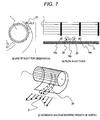
- Fig. 7 is a schematic view showing a flow of a blow course of an air blower equipped with the related art cross flow fan.
- a gap generated between a cross flow fan 1 and a rear guide 13, which is a member configuring the air trunk is observed from a position above an air conditioner.
- Fig. 7(b) is a view schematically showing the flow generated at this time. Since the gap becomes narrow at the ring part, a fast flow 19a develops. In the meantime, since the gap becomes wide at the blade part, a slow flow 19b develops. When a velocity difference occurs in a widthwise direction as mentioned above, a second flow that is a mixture of the fast flow 19a and the slow flow 19b develops.
- a vortex 20 whose axis is oriented along a direction of the blow course grows. As shown in Figs. 7(c) , the vortex extends to a downstream of the air trunk, to thus become gradually greater and hinder an air flow at a blow outlet. Thus, variations in velocity distribution 21 achieved in a widthwise direction at the blow outlet become noticeable.
- Fig. 8 is a view showing a simulation result of velocity of a blow course of the related art air blower.
- An upper drawing of Fig. 8 is a front view of an air conditioner, and numbers 1 through 20 depicting points of observation are provided at a position below the cross flow fan configured by the rings 2 and the blades 3.
- a lower drawing of Fig. 8 is a graph showing an average wind velocity achieved at each of the points of observation. When viewed together with the upper drawing of Fig. 8 , it can be seen that the average wind velocity assumes a local maximum value near each of the rings 2. When a local high speed flow collides against blades for controlling a direction of wind at the blow outlet, a pressure loss contributing a square of wind velocity becomes greater. Further, variations in pressure exerted on surfaces of the blades for adjusting the direction of the wind also become greater, whereby a noise value also becomes greater.
- gap between the blades and the air trunk member becomes narrow in an area where a blade chord length is long and where an outer diameter of the fan is large, and the flow of the blow also becomes faster in the area. For these reasons, there is a problem that abnormal sound stemming from the air trunk member increases. Moreover, a contact may occur between the blades and the air trunk member due to a manufacturing error, or the like.
- the present invention has been conceived to solve the above-described problems and the object of the thereof is to provide a cross flow fan that makes uniform the distribution of wind velocity along an axial direction of a fan at an exit of an air trunk, in consideration of variations in wind velocity of a air flow passing through gap between the cross flow fan and the air trunk member, and that realizes reduced separation of the airflow at an inlet side of the fan, thereby providing a cross flow fan that realizes reduced input and noise and an air blower or an air conditioner using the cross flow fan.
- a cross flow fan according to claim 1 defines the present invention.
- the word 'embodiment' simply means 'example' and does not imply that the example is part of the invention.
- the use of the word 'aspect' to introduce (or to refer) some subject-matter does not imply that this subject-matter is part of the invention.
- the words 'embodiments' and/or 'aspects' are used to refer to the invention, this will be stated explicitly.
- the invention is defined by the appended claims only.
- the present invention makes it possible to make a distribution of wind velocity along a longitudinal direction of a fan at an exit of an air trunk uniform in consideration of variations in wind velocity of an air flow passing through gap between the cross flow fan and an air trunk member.
- a cross flow fan that realizes a reduced input and smaller noise and an air blower or an air conditioner using the cross flow fan.
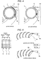
- Fig. 1(a) is an oblique perspective view showing an appearance of a cross flow fan 1 of a first embodiment.
- a plurality of blades 3, each of which is at both ends thereof supported by rings 2, are provided along a circumferential direction of the rings 2.
- Some single impellers 4 (hereinafter called a "single wheel”), each of which is made up of the rings 2 and the blades 3, are joined together along an axial direction of a fan, to thus configure the cross flow fan 1.
- Fig. 1(b) is a front view of a main section of the single impeller 4. As shown in Fig. 1(b) , an outer diameter defined by outer edges of the blades 3 is constant along the axial direction of the cross flow fan 1.
- Fig. 1(b) an outer diameter defined by outer edges of the blades 3 is constant along the axial direction of the cross flow fan 1.
- FIG. 1(c) shows a longitudinal cross sectional view of the impeller of the single wheel.
- a ring outer diameter 5 is larger than the outer diameter of the blades 3, and the blades 3 are radially, fixedly bonded to the ring 2 at an inside with reference to an outer circumference of the ring 2. Further, each of the blades 3 is formed in a circular-arc cross sectional shape.
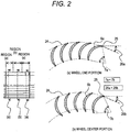
- Fig. 2 is a longitudinal cross sectional view of the cross flow fan 1 of the first embodiment.
- the blades 3 of the impeller of the single wheel, which are sandwiched between the rings, are divided into three regions (a), (b), and (a) from the left, and the cross sectional shape of the blade differs in each region.
- a division ratio of the region (a) is set to about one-third to less than one-half of a length of the single wheel.
- the regions (a) of the blades 3 close to the respective rings 2 are hereinafter called “wheel end portions," whilst the region (b) of the blade center is hereinafter called a “wheel center portion.”
- Fig. 2(a) is a longitudinal cross sectional view of the wheel end portion
- Fig. 2(b) is a longitudinal cross sectional view of the wheel center portion.
- a center of a thickness of each blade, from a blade leading end that configures an outer periphery of the blade 3 to a rear end that configures an inner periphery of the blade 3, is defined as a blade center line.
- the blade center line of the wheel end portion is assigned reference numeral 6a
- the blade center line of the wheel center portion is assigned reference numeral 6b.
- Angles that the blade leading ends of the blade center lines 6a, 6b form with the rear ends of the blade center lines 6a, 6b are respectively defined as camber angles 7a, 7b.
- the amber angle 7b of the wheel center portion is made larger than the camber angle 7a of the wheel end portion (7a ⁇ 7b).
- the exit angle means an angle that a tangential line of the blade center line 6a (or 6b) and a tangential line of the circular arc 24 along the outer diameter of the blades form at the point of intersection 25.
- the blade center line 6b can be extended toward the inner circumference of the blade 3.
- a blade chord length which will be described later, can be extended toward the inner circumference on condition that the exit angle 26b remains unchanged. This alternative is an embodiment of the invention.
- Fig. 3 is a longitudinal cross sectional view of an air conditioner using the cross flow fan 1.
- a heat exchanger 8 that exchanges heat between air and a coolant is disposed so as to enclose surroundings of the cross flow fan 1.
- a suction opening 30 are formed in an upper surface of the air conditioner.
- An air purifier 9 and a filter 10 are interposed between the suction opening 30 and the heat exchanger 8.
- An inlet side and an outlet side of the cross flow fan 1 are partitioned by a stabilizer 12 attached to an extremity of a nozzle 11 located on a front side of the unit and a rear guide 13 located on a rear side of the unit.
- a stabilizer 12 attached to an extremity of a nozzle 11 located on a front side of the unit and a rear guide 13 located on a rear side of the unit.
- an air trunk extending from the suction opening 30 to the blow outlet 17 is divided into two.
- the blow outlet 17 is provided with a vane 16 for adjusting a wind direction.
- Fig. 4 is a longitudinal cross sectional view of a main section of the air conditioner using the cross flow fan of the first embodiment.
- a gap between the rings 2 and the rear guide 13 is narrower than a gap between the blades 3 and the rear guide 13.
- An air flow 19a passed near the rings becomes faster than an air flow 19b passed near the blades.
- the camber angle of each of the blades 3 achieved at the wheel center portion becomes larger than the camber angle of each of the blades 3 achieved at the wheel end portion.
- workload imparted to the airflow by the blades 3 at the wheel center portion is larger than workload imparted to the airflow by the blades 3 at the wheel end portion.
- an air flow 22b exiting out of the wheel center portion becomes faster than an air flow 22a exiting out of the wheel end portion.
- a speed of the faster air flow 19a passed through the gap in the vicinity of the rings is increased by the slower air flow 22a.
- a speed of the slower air flow 19b passed near the blades is increased by the faster air flow 22b.
- the slower air flow 19b passed near the blades is increased speed by the faster air flow 22b, a difference between the wind velocity of the air flow 19a and the wind velocity of the air flow 19b achieved at a downstream of the fan can be reduced.
- the workload imparted by the blades to the air flow passed through the gap between the cross flow fan 1 and the rear guide 13 is changed, whereby the difference between the wind velocity of the air flow from the wheel end portion at the downstream of the fan and the wind velocity of the air flow from wheel center portion at the downstream of the fan becomes smaller, and hence occurrence of a vortex, which would otherwise be caused by a difference in wind velocity, can be prevented.
- the distribution of wind achieved at downstream of the fan is made uniform.
- the air flow having a uniform distribution of wind velocity at the downstream of the fan is let outside the unit by way of the blow outlet 17 along the direction defined by the vane 16 for controlling an air flow.
- the exit angles 26 are made uniform, so that an inflow state of air to extremities of the respective blades is made uniform. As a consequence, a distribution of wind velocity achieved in an air blow trunk can be made uniform without deteriorating noise, which would otherwise be caused when inflow air is separated by a row of blades.
- Table 1 shows results of comparative tests conducted by use of an air conditioner using a related art cross flow fan and the air conditioner of the first embodiment. Table 1 shows differences in fan power and noise. As illustrated in Table 1, it turns out that both power and noise are lessened and improved by use of the cross flow fan of the first embodiment.
- an outer diameter of each of the blades 3 is made constant.
- a distribution of velocity that is caused, in the air blower and the air conditioner, by differences in gap between the cross flow fan 1 and the rear guide 13 is canceled by the distribution of wind velocity of a blow of the cross flow fan. Therefore, a vortex that acts as resistance to the air flow disappears, and the distribution of wind velocity achieved at the exit of the air trunk can be made uniform.
- the exit angles being made uniform, there can be realized a cross flow fan that is free from hindrance to passage of an air flow among blades and separation of the air flow.
- an increase or decrease in the volume of air blow is changed by camber of the blades.
- the volume of air can also be changed by the blade chord length.
- Fig. 5 is a longitudinal cross sectional view of the cross flow fan 1 of a second embodiment, which is part of the invention.
- the cross section of the impeller for one wheel is illustrated while separated into the wheel end portion (a) and the wheel center portion (b) as in the first embodiment.
- a straight line (a blade chord length 23) from the extremity of the blade to the rear end of the blade is characterized in that a blade chord length 23b of the wheel center portion is longer than a blade chord length 23a of the wheel end portion (23a ⁇ 23b).
- the outer diameter of each of the blades 3 is made uniform, and the distribution of velocity caused by differences in gap between the fan and the air trunk developing in the air blower or the air conditioner is canceled by the distribution of velocity of the blow of the cross flow fan, as in the first embodiment.
- the direction of an outer circumference edge of the blades is made uniform with respect to the direction of the air flow achieved on the inlet side. This yields an advantage of the ability to realize a cross flow fan that prevents hindrance to passage of an air flow among blades and air flow separation. Even in an air blower and an air conditioner that yield large differences in wind velocity of a blow from the fan, the distribution of wind velocity achieved at the exit of air trunk is made uniform. There is yielded an advantage of accomplishment of a smaller pressure loss caused by a vane, a smaller input, and lower noise.
- the type of a parameter of blade shape is changed one at a time.
- the differences in wind velocity occurred in the wind trunk are large, the velocity distribution of fan blow must be intensified.
- a blade shape that is a combination of parameters, like the blade chord length and camber.
- each of the blades belonging to a single wheel of the impellers changes in shape along its widthwise direction.
- a step appears in the surface of the blade when the shape is sharply changed.
- the step may induce a vortex on the surface of the blade or increase pressure fluctuations, which may in turn deteriorate noise.
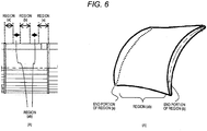
- Fig. 6(A) is a front view of a cross flow fan of the third embodiment, which is part of the invention
- Fig. 6(B) is an oblique perspective view of the cross flow fan of a region (ab) shown in Fig. 6(A)
- the region (ab) which is a continuous inclined surface, is provided between the region (a) and the region (b) of the impeller.
- the shape of the blade is smoothly changed so that a step will not arise on the surface of the blade between the region (a) and the region (b).
- the step is absent from the surface of the blade, which yields an advantage of prevention of occurrence of a vortex at the surface and development of noise caused by pressure fluctuations.
- an air blower or an air conditioner is equipped with the cross flow fan, the distribution of wind velocity achieved at downstream of the fan is made uniform while influence of the changes in shape of the blades is suppressed, whereby there is yielded an advantage of the ability to implement an air blower and an air conditioner that realizes a smaller input and reduced noise.
- the present invention yields a similar advantage even when applied to another equipment using the cross flow fan, like an air purification apparatus or a dehumidification apparatus.
Landscapes
- Engineering & Computer Science (AREA)
- Mechanical Engineering (AREA)
- General Engineering & Computer Science (AREA)
- Structures Of Non-Positive Displacement Pumps (AREA)
Applications Claiming Priority (2)
| Application Number | Priority Date | Filing Date | Title |
|---|---|---|---|
| JP2009222563A JP4998530B2 (ja) | 2009-09-28 | 2009-09-28 | 貫流ファン、送風機及び空気調和機 |
| PCT/JP2010/005476 WO2011036848A1 (ja) | 2009-09-28 | 2010-09-07 | 貫流ファン、送風機及び空気調和機 |
Publications (3)
| Publication Number | Publication Date |
|---|---|
| EP2472118A1 EP2472118A1 (en) | 2012-07-04 |
| EP2472118A4 EP2472118A4 (en) | 2017-07-05 |
| EP2472118B1 true EP2472118B1 (en) | 2019-05-08 |
Family
ID=43795618
Family Applications (1)
| Application Number | Title | Priority Date | Filing Date |
|---|---|---|---|
| EP10818529.9A Not-in-force EP2472118B1 (en) | 2009-09-28 | 2010-09-07 | Cross flow fan and air conditioner |
Country Status (6)
| Country | Link |
|---|---|
| US (1) | US9039347B2 (enExample) |
| EP (1) | EP2472118B1 (enExample) |
| JP (1) | JP4998530B2 (enExample) |
| CN (1) | CN102686887B (enExample) |
| ES (1) | ES2729480T3 (enExample) |
| WO (1) | WO2011036848A1 (enExample) |
Families Citing this family (15)
| Publication number | Priority date | Publication date | Assignee | Title |
|---|---|---|---|---|
| JP5269060B2 (ja) * | 2010-12-24 | 2013-08-21 | 三菱電機株式会社 | 貫流ファン及び空気調和機の室内機 |
| CN103429906B (zh) * | 2011-03-11 | 2016-04-27 | 三菱电机株式会社 | 贯流风扇和送风机以及空气调节机 |
| JP5143317B1 (ja) * | 2012-04-06 | 2013-02-13 | 三菱電機株式会社 | 空気調和装置の室内機 |
| JP5533969B2 (ja) * | 2012-09-28 | 2014-06-25 | ダイキン工業株式会社 | 空気調和機 |
| JP5991898B2 (ja) * | 2012-10-30 | 2016-09-14 | 三菱電機株式会社 | クロスフローファン |
| KR102143389B1 (ko) * | 2013-03-20 | 2020-08-28 | 삼성전자주식회사 | 원심팬 및 이를 포함하는 공기조화기 |
| DE102014013755B4 (de) * | 2014-09-22 | 2021-07-01 | Dinghan SMART Railway Technology GmbH | Lüfteranordnung und leistungselektronische Schaltung |
| CN106321473B (zh) * | 2016-09-05 | 2019-02-05 | 青岛海尔空调器有限总公司 | 用于空调器的贯流风机 |
| CN108708876A (zh) * | 2018-05-16 | 2018-10-26 | 广东美的环境电器制造有限公司 | 叶片调节机构和空气循环器 |
| CN110043511B (zh) * | 2018-05-18 | 2024-11-26 | 广东美的制冷设备有限公司 | 风轮及其叶片 |
| GB2575064B (en) | 2018-06-27 | 2021-06-09 | Dyson Technology Ltd | A nozzle for a fan assembly |
| GB2578617B (en) * | 2018-11-01 | 2021-02-24 | Dyson Technology Ltd | A nozzle for a fan assembly |
| KR102782040B1 (ko) * | 2020-02-25 | 2025-03-13 | 엘지전자 주식회사 | 횡류팬 |
| CN214660989U (zh) * | 2021-04-30 | 2021-11-09 | 中强光电股份有限公司 | 风扇结构 |
| GB2608124B (en) | 2021-06-22 | 2023-11-15 | Dyson Technology Ltd | Nozzle for a fan assembly |
Citations (1)
| Publication number | Priority date | Publication date | Assignee | Title |
|---|---|---|---|---|
| JP3260544B2 (ja) * | 1994-04-06 | 2002-02-25 | 松下精工株式会社 | 多翼ファン |
Family Cites Families (9)
| Publication number | Priority date | Publication date | Assignee | Title |
|---|---|---|---|---|
| JP2594063B2 (ja) | 1987-10-09 | 1997-03-26 | 三洋電機株式会社 | 送風装置 |
| JP2591615Y2 (ja) * | 1993-12-31 | 1999-03-10 | 日本高分子株式会社 | 円筒形羽根車 |
| JPH081320A (ja) * | 1994-06-20 | 1996-01-09 | Hitachi Ltd | ろう付け曲面積層パネルおよびその製作方法 |
| JP3918207B2 (ja) * | 1995-08-02 | 2007-05-23 | 株式会社日立製作所 | 空気調和機 |
| JP3137897B2 (ja) | 1996-03-12 | 2001-02-26 | 株式会社日立製作所 | 貫流ファン |
| JP3777891B2 (ja) * | 1999-08-03 | 2006-05-24 | 株式会社日立製作所 | 空気調和機 |
| JP2001280288A (ja) * | 2000-03-31 | 2001-10-10 | Daikin Ind Ltd | 多翼送風機の羽根車構造 |
| JP2006152886A (ja) * | 2004-11-26 | 2006-06-15 | Toshiba Kyaria Kk | 横流ファン、空気調和機の室内機 |
| JP2006329099A (ja) | 2005-05-27 | 2006-12-07 | Daikin Ind Ltd | クロスフローファン |
-
2009
- 2009-09-28 JP JP2009222563A patent/JP4998530B2/ja not_active Expired - Fee Related
-
2010
- 2010-09-07 US US13/497,287 patent/US9039347B2/en active Active
- 2010-09-07 EP EP10818529.9A patent/EP2472118B1/en not_active Not-in-force
- 2010-09-07 CN CN201080043124.8A patent/CN102686887B/zh not_active Expired - Fee Related
- 2010-09-07 WO PCT/JP2010/005476 patent/WO2011036848A1/ja not_active Ceased
- 2010-09-07 ES ES10818529T patent/ES2729480T3/es active Active
Patent Citations (1)
| Publication number | Priority date | Publication date | Assignee | Title |
|---|---|---|---|---|
| JP3260544B2 (ja) * | 1994-04-06 | 2002-02-25 | 松下精工株式会社 | 多翼ファン |
Also Published As
| Publication number | Publication date |
|---|---|
| US20120263573A1 (en) | 2012-10-18 |
| JP4998530B2 (ja) | 2012-08-15 |
| CN102686887A (zh) | 2012-09-19 |
| HK1175516A1 (zh) | 2013-07-05 |
| US9039347B2 (en) | 2015-05-26 |
| ES2729480T3 (es) | 2019-11-04 |
| CN102686887B (zh) | 2015-11-25 |
| EP2472118A4 (en) | 2017-07-05 |
| EP2472118A1 (en) | 2012-07-04 |
| WO2011036848A1 (ja) | 2011-03-31 |
| JP2011069320A (ja) | 2011-04-07 |
Similar Documents
| Publication | Publication Date | Title |
|---|---|---|
| EP2472118B1 (en) | Cross flow fan and air conditioner | |
| EP3842644B1 (en) | Counter-rotating fan | |
| EP2233847B1 (en) | Air conditioner | |
| CN107850083B (zh) | 送风机和搭载有该送风机的空调装置 | |
| JP3698150B2 (ja) | 遠心送風機 | |
| JP4690682B2 (ja) | 空調機 | |
| JP2011069320A5 (enExample) | ||
| WO2011062062A1 (ja) | 遠心式送風機の多翼ファン | |
| JP2012092680A (ja) | 多翼遠心ファンおよびそれを用いた空気調和機 | |
| EP2960525B1 (en) | Propeller fan and air conditioner equipped with same | |
| JP4989705B2 (ja) | 貫流ファン及び送風機及び空気調和機 | |
| JP4687675B2 (ja) | 貫流送風機および空気調和機 | |
| JP6005256B2 (ja) | 羽根車及びこれを用いた軸流送風機 | |
| JP2008232049A (ja) | 遠心羽根車と遠心送風機 | |
| JP2012140881A (ja) | 多翼送風機 | |
| JP5879486B2 (ja) | 送風装置 | |
| JP4994433B2 (ja) | シロッコファン及びこのシロッコファンを用いた空気調和機の室内機 | |
| JP6972385B2 (ja) | 遠心送風機 | |
| US9453512B2 (en) | Cross flow fan, air-sending device, and air-conditioning apparatus | |
| KR200467395Y1 (ko) | 송풍장치 | |
| JP7555474B2 (ja) | 送風装置および空気調和装置 | |
| JP5460749B2 (ja) | 貫流ファン及び送風機及び空気調和機 | |
| JPH08210665A (ja) | 空気調和装置用室外機 | |
| JPH06299994A (ja) | 多翼ファン | |
| EP3587937B1 (en) | Air conditioning indoor unit |
Legal Events
| Date | Code | Title | Description |
|---|---|---|---|
| PUAI | Public reference made under article 153(3) epc to a published international application that has entered the european phase |
Free format text: ORIGINAL CODE: 0009012 |
|
| 17P | Request for examination filed |
Effective date: 20120322 |
|
| AK | Designated contracting states |
Kind code of ref document: A1 Designated state(s): AL AT BE BG CH CY CZ DE DK EE ES FI FR GB GR HR HU IE IS IT LI LT LU LV MC MK MT NL NO PL PT RO SE SI SK SM TR |
|
| DAX | Request for extension of the european patent (deleted) | ||
| RA4 | Supplementary search report drawn up and despatched (corrected) |
Effective date: 20170606 |
|
| RIC1 | Information provided on ipc code assigned before grant |
Ipc: F04D 29/28 20060101ALI20170530BHEP Ipc: F04D 17/04 20060101AFI20170530BHEP Ipc: F04D 29/66 20060101ALI20170530BHEP Ipc: F04D 29/30 20060101ALI20170530BHEP |
|
| STAA | Information on the status of an ep patent application or granted ep patent |
Free format text: STATUS: EXAMINATION IS IN PROGRESS |
|
| 17Q | First examination report despatched |
Effective date: 20180205 |
|
| GRAP | Despatch of communication of intention to grant a patent |
Free format text: ORIGINAL CODE: EPIDOSNIGR1 |
|
| STAA | Information on the status of an ep patent application or granted ep patent |
Free format text: STATUS: GRANT OF PATENT IS INTENDED |
|
| INTG | Intention to grant announced |
Effective date: 20181120 |
|
| GRAS | Grant fee paid |
Free format text: ORIGINAL CODE: EPIDOSNIGR3 |
|
| GRAA | (expected) grant |
Free format text: ORIGINAL CODE: 0009210 |
|
| STAA | Information on the status of an ep patent application or granted ep patent |
Free format text: STATUS: THE PATENT HAS BEEN GRANTED |
|
| AK | Designated contracting states |
Kind code of ref document: B1 Designated state(s): AL AT BE BG CH CY CZ DE DK EE ES FI FR GB GR HR HU IE IS IT LI LT LU LV MC MK MT NL NO PL PT RO SE SI SK SM TR |
|
| REG | Reference to a national code |
Ref country code: GB Ref legal event code: FG4D |
|
| REG | Reference to a national code |
Ref country code: CH Ref legal event code: EP Ref country code: AT Ref legal event code: REF Ref document number: 1130557 Country of ref document: AT Kind code of ref document: T Effective date: 20190515 |
|
| REG | Reference to a national code |
Ref country code: DE Ref legal event code: R096 Ref document number: 602010058814 Country of ref document: DE Ref country code: IE Ref legal event code: FG4D |
|
| REG | Reference to a national code |
Ref country code: NL Ref legal event code: MP Effective date: 20190508 |
|
| REG | Reference to a national code |
Ref country code: LT Ref legal event code: MG4D |
|
| PG25 | Lapsed in a contracting state [announced via postgrant information from national office to epo] |
Ref country code: AL Free format text: LAPSE BECAUSE OF FAILURE TO SUBMIT A TRANSLATION OF THE DESCRIPTION OR TO PAY THE FEE WITHIN THE PRESCRIBED TIME-LIMIT Effective date: 20190508 Ref country code: PT Free format text: LAPSE BECAUSE OF FAILURE TO SUBMIT A TRANSLATION OF THE DESCRIPTION OR TO PAY THE FEE WITHIN THE PRESCRIBED TIME-LIMIT Effective date: 20190908 Ref country code: FI Free format text: LAPSE BECAUSE OF FAILURE TO SUBMIT A TRANSLATION OF THE DESCRIPTION OR TO PAY THE FEE WITHIN THE PRESCRIBED TIME-LIMIT Effective date: 20190508 Ref country code: LT Free format text: LAPSE BECAUSE OF FAILURE TO SUBMIT A TRANSLATION OF THE DESCRIPTION OR TO PAY THE FEE WITHIN THE PRESCRIBED TIME-LIMIT Effective date: 20190508 Ref country code: HR Free format text: LAPSE BECAUSE OF FAILURE TO SUBMIT A TRANSLATION OF THE DESCRIPTION OR TO PAY THE FEE WITHIN THE PRESCRIBED TIME-LIMIT Effective date: 20190508 Ref country code: NL Free format text: LAPSE BECAUSE OF FAILURE TO SUBMIT A TRANSLATION OF THE DESCRIPTION OR TO PAY THE FEE WITHIN THE PRESCRIBED TIME-LIMIT Effective date: 20190508 Ref country code: SE Free format text: LAPSE BECAUSE OF FAILURE TO SUBMIT A TRANSLATION OF THE DESCRIPTION OR TO PAY THE FEE WITHIN THE PRESCRIBED TIME-LIMIT Effective date: 20190508 Ref country code: NO Free format text: LAPSE BECAUSE OF FAILURE TO SUBMIT A TRANSLATION OF THE DESCRIPTION OR TO PAY THE FEE WITHIN THE PRESCRIBED TIME-LIMIT Effective date: 20190808 |
|
| REG | Reference to a national code |
Ref country code: ES Ref legal event code: FG2A Ref document number: 2729480 Country of ref document: ES Kind code of ref document: T3 Effective date: 20191104 |
|
| PG25 | Lapsed in a contracting state [announced via postgrant information from national office to epo] |
Ref country code: BG Free format text: LAPSE BECAUSE OF FAILURE TO SUBMIT A TRANSLATION OF THE DESCRIPTION OR TO PAY THE FEE WITHIN THE PRESCRIBED TIME-LIMIT Effective date: 20190808 Ref country code: GR Free format text: LAPSE BECAUSE OF FAILURE TO SUBMIT A TRANSLATION OF THE DESCRIPTION OR TO PAY THE FEE WITHIN THE PRESCRIBED TIME-LIMIT Effective date: 20190809 Ref country code: LV Free format text: LAPSE BECAUSE OF FAILURE TO SUBMIT A TRANSLATION OF THE DESCRIPTION OR TO PAY THE FEE WITHIN THE PRESCRIBED TIME-LIMIT Effective date: 20190508 |
|
| REG | Reference to a national code |
Ref country code: AT Ref legal event code: MK05 Ref document number: 1130557 Country of ref document: AT Kind code of ref document: T Effective date: 20190508 |
|
| PG25 | Lapsed in a contracting state [announced via postgrant information from national office to epo] |
Ref country code: CZ Free format text: LAPSE BECAUSE OF FAILURE TO SUBMIT A TRANSLATION OF THE DESCRIPTION OR TO PAY THE FEE WITHIN THE PRESCRIBED TIME-LIMIT Effective date: 20190508 Ref country code: RO Free format text: LAPSE BECAUSE OF FAILURE TO SUBMIT A TRANSLATION OF THE DESCRIPTION OR TO PAY THE FEE WITHIN THE PRESCRIBED TIME-LIMIT Effective date: 20190508 Ref country code: DK Free format text: LAPSE BECAUSE OF FAILURE TO SUBMIT A TRANSLATION OF THE DESCRIPTION OR TO PAY THE FEE WITHIN THE PRESCRIBED TIME-LIMIT Effective date: 20190508 Ref country code: AT Free format text: LAPSE BECAUSE OF FAILURE TO SUBMIT A TRANSLATION OF THE DESCRIPTION OR TO PAY THE FEE WITHIN THE PRESCRIBED TIME-LIMIT Effective date: 20190508 Ref country code: EE Free format text: LAPSE BECAUSE OF FAILURE TO SUBMIT A TRANSLATION OF THE DESCRIPTION OR TO PAY THE FEE WITHIN THE PRESCRIBED TIME-LIMIT Effective date: 20190508 Ref country code: SK Free format text: LAPSE BECAUSE OF FAILURE TO SUBMIT A TRANSLATION OF THE DESCRIPTION OR TO PAY THE FEE WITHIN THE PRESCRIBED TIME-LIMIT Effective date: 20190508 |
|
| REG | Reference to a national code |
Ref country code: DE Ref legal event code: R097 Ref document number: 602010058814 Country of ref document: DE |
|
| PG25 | Lapsed in a contracting state [announced via postgrant information from national office to epo] |
Ref country code: SM Free format text: LAPSE BECAUSE OF FAILURE TO SUBMIT A TRANSLATION OF THE DESCRIPTION OR TO PAY THE FEE WITHIN THE PRESCRIBED TIME-LIMIT Effective date: 20190508 |
|
| PLBE | No opposition filed within time limit |
Free format text: ORIGINAL CODE: 0009261 |
|
| STAA | Information on the status of an ep patent application or granted ep patent |
Free format text: STATUS: NO OPPOSITION FILED WITHIN TIME LIMIT |
|
| PG25 | Lapsed in a contracting state [announced via postgrant information from national office to epo] |
Ref country code: TR Free format text: LAPSE BECAUSE OF FAILURE TO SUBMIT A TRANSLATION OF THE DESCRIPTION OR TO PAY THE FEE WITHIN THE PRESCRIBED TIME-LIMIT Effective date: 20190508 |
|
| REG | Reference to a national code |
Ref country code: DE Ref legal event code: R119 Ref document number: 602010058814 Country of ref document: DE |
|
| 26N | No opposition filed |
Effective date: 20200211 |
|
| PG25 | Lapsed in a contracting state [announced via postgrant information from national office to epo] |
Ref country code: PL Free format text: LAPSE BECAUSE OF FAILURE TO SUBMIT A TRANSLATION OF THE DESCRIPTION OR TO PAY THE FEE WITHIN THE PRESCRIBED TIME-LIMIT Effective date: 20190508 |
|
| PG25 | Lapsed in a contracting state [announced via postgrant information from national office to epo] |
Ref country code: MC Free format text: LAPSE BECAUSE OF FAILURE TO SUBMIT A TRANSLATION OF THE DESCRIPTION OR TO PAY THE FEE WITHIN THE PRESCRIBED TIME-LIMIT Effective date: 20190508 Ref country code: SI Free format text: LAPSE BECAUSE OF FAILURE TO SUBMIT A TRANSLATION OF THE DESCRIPTION OR TO PAY THE FEE WITHIN THE PRESCRIBED TIME-LIMIT Effective date: 20190508 |
|
| REG | Reference to a national code |
Ref country code: CH Ref legal event code: PL |
|
| PG25 | Lapsed in a contracting state [announced via postgrant information from national office to epo] |
Ref country code: CH Free format text: LAPSE BECAUSE OF NON-PAYMENT OF DUE FEES Effective date: 20190930 Ref country code: LU Free format text: LAPSE BECAUSE OF NON-PAYMENT OF DUE FEES Effective date: 20190907 Ref country code: DE Free format text: LAPSE BECAUSE OF NON-PAYMENT OF DUE FEES Effective date: 20200401 Ref country code: LI Free format text: LAPSE BECAUSE OF NON-PAYMENT OF DUE FEES Effective date: 20190930 Ref country code: IE Free format text: LAPSE BECAUSE OF NON-PAYMENT OF DUE FEES Effective date: 20190907 |
|
| REG | Reference to a national code |
Ref country code: BE Ref legal event code: MM Effective date: 20190930 |
|
| PG25 | Lapsed in a contracting state [announced via postgrant information from national office to epo] |
Ref country code: BE Free format text: LAPSE BECAUSE OF NON-PAYMENT OF DUE FEES Effective date: 20190930 |
|
| GBPC | Gb: european patent ceased through non-payment of renewal fee |
Effective date: 20190907 |
|
| PG25 | Lapsed in a contracting state [announced via postgrant information from national office to epo] |
Ref country code: FR Free format text: LAPSE BECAUSE OF NON-PAYMENT OF DUE FEES Effective date: 20190930 Ref country code: GB Free format text: LAPSE BECAUSE OF NON-PAYMENT OF DUE FEES Effective date: 20190907 |
|
| PG25 | Lapsed in a contracting state [announced via postgrant information from national office to epo] |
Ref country code: CY Free format text: LAPSE BECAUSE OF FAILURE TO SUBMIT A TRANSLATION OF THE DESCRIPTION OR TO PAY THE FEE WITHIN THE PRESCRIBED TIME-LIMIT Effective date: 20190508 |
|
| PG25 | Lapsed in a contracting state [announced via postgrant information from national office to epo] |
Ref country code: IS Free format text: LAPSE BECAUSE OF FAILURE TO SUBMIT A TRANSLATION OF THE DESCRIPTION OR TO PAY THE FEE WITHIN THE PRESCRIBED TIME-LIMIT Effective date: 20190908 |
|
| PG25 | Lapsed in a contracting state [announced via postgrant information from national office to epo] |
Ref country code: MT Free format text: LAPSE BECAUSE OF FAILURE TO SUBMIT A TRANSLATION OF THE DESCRIPTION OR TO PAY THE FEE WITHIN THE PRESCRIBED TIME-LIMIT Effective date: 20190508 Ref country code: HU Free format text: LAPSE BECAUSE OF FAILURE TO SUBMIT A TRANSLATION OF THE DESCRIPTION OR TO PAY THE FEE WITHIN THE PRESCRIBED TIME-LIMIT; INVALID AB INITIO Effective date: 20100907 |
|
| PG25 | Lapsed in a contracting state [announced via postgrant information from national office to epo] |
Ref country code: MK Free format text: LAPSE BECAUSE OF FAILURE TO SUBMIT A TRANSLATION OF THE DESCRIPTION OR TO PAY THE FEE WITHIN THE PRESCRIBED TIME-LIMIT Effective date: 20190508 |
|
| P01 | Opt-out of the competence of the unified patent court (upc) registered |
Effective date: 20230512 |
|
| PGFP | Annual fee paid to national office [announced via postgrant information from national office to epo] |
Ref country code: IT Payment date: 20230810 Year of fee payment: 14 |
|
| PGFP | Annual fee paid to national office [announced via postgrant information from national office to epo] |
Ref country code: ES Payment date: 20231003 Year of fee payment: 14 |
|
| REG | Reference to a national code |
Ref country code: ES Ref legal event code: GC2A Effective date: 20240410 |
|
| PG25 | Lapsed in a contracting state [announced via postgrant information from national office to epo] |
Ref country code: IT Free format text: LAPSE BECAUSE OF NON-PAYMENT OF DUE FEES Effective date: 20240907 |
|
| REG | Reference to a national code |
Ref country code: ES Ref legal event code: FD2A Effective date: 20251028 |