EP2471131B1 - Elektrochemisches element mit reduziertem innenwiderstand - Google Patents
Elektrochemisches element mit reduziertem innenwiderstand Download PDFInfo
- Publication number
- EP2471131B1 EP2471131B1 EP10732358.6A EP10732358A EP2471131B1 EP 2471131 B1 EP2471131 B1 EP 2471131B1 EP 10732358 A EP10732358 A EP 10732358A EP 2471131 B1 EP2471131 B1 EP 2471131B1
- Authority
- EP
- European Patent Office
- Prior art keywords
- electrode
- electrochemical element
- element according
- housing
- segments
- Prior art date
- Legal status (The legal status is an assumption and is not a legal conclusion. Google has not performed a legal analysis and makes no representation as to the accuracy of the status listed.)
- Active
Links
Images

Classifications
-
- H—ELECTRICITY
- H01—ELECTRIC ELEMENTS
- H01M—PROCESSES OR MEANS, e.g. BATTERIES, FOR THE DIRECT CONVERSION OF CHEMICAL ENERGY INTO ELECTRICAL ENERGY
- H01M4/00—Electrodes
- H01M4/02—Electrodes composed of, or comprising, active material
- H01M4/06—Electrodes for primary cells
-
- H—ELECTRICITY
- H01—ELECTRIC ELEMENTS
- H01M—PROCESSES OR MEANS, e.g. BATTERIES, FOR THE DIRECT CONVERSION OF CHEMICAL ENERGY INTO ELECTRICAL ENERGY
- H01M4/00—Electrodes
- H01M4/02—Electrodes composed of, or comprising, active material
- H01M4/64—Carriers or collectors
- H01M4/66—Selection of materials
- H01M4/661—Metal or alloys, e.g. alloy coatings
-
- H—ELECTRICITY
- H01—ELECTRIC ELEMENTS
- H01M—PROCESSES OR MEANS, e.g. BATTERIES, FOR THE DIRECT CONVERSION OF CHEMICAL ENERGY INTO ELECTRICAL ENERGY
- H01M4/00—Electrodes
- H01M4/02—Electrodes composed of, or comprising, active material
- H01M4/64—Carriers or collectors
- H01M4/66—Selection of materials
- H01M4/663—Selection of materials containing carbon or carbonaceous materials as conductive part, e.g. graphite, carbon fibres
-
- H—ELECTRICITY
- H01—ELECTRIC ELEMENTS
- H01M—PROCESSES OR MEANS, e.g. BATTERIES, FOR THE DIRECT CONVERSION OF CHEMICAL ENERGY INTO ELECTRICAL ENERGY
- H01M6/00—Primary cells; Manufacture thereof
- H01M6/04—Cells with aqueous electrolyte
- H01M6/06—Dry cells, i.e. cells wherein the electrolyte is rendered non-fluid
- H01M6/08—Dry cells, i.e. cells wherein the electrolyte is rendered non-fluid with cup-shaped electrodes
- H01M6/085—Dry cells, i.e. cells wherein the electrolyte is rendered non-fluid with cup-shaped electrodes of the reversed type, i.e. anode in the centre
-
- Y—GENERAL TAGGING OF NEW TECHNOLOGICAL DEVELOPMENTS; GENERAL TAGGING OF CROSS-SECTIONAL TECHNOLOGIES SPANNING OVER SEVERAL SECTIONS OF THE IPC; TECHNICAL SUBJECTS COVERED BY FORMER USPC CROSS-REFERENCE ART COLLECTIONS [XRACs] AND DIGESTS
- Y02—TECHNOLOGIES OR APPLICATIONS FOR MITIGATION OR ADAPTATION AGAINST CLIMATE CHANGE
- Y02E—REDUCTION OF GREENHOUSE GAS [GHG] EMISSIONS, RELATED TO ENERGY GENERATION, TRANSMISSION OR DISTRIBUTION
- Y02E60/00—Enabling technologies; Technologies with a potential or indirect contribution to GHG emissions mitigation
- Y02E60/10—Energy storage using batteries
-
- Y—GENERAL TAGGING OF NEW TECHNOLOGICAL DEVELOPMENTS; GENERAL TAGGING OF CROSS-SECTIONAL TECHNOLOGIES SPANNING OVER SEVERAL SECTIONS OF THE IPC; TECHNICAL SUBJECTS COVERED BY FORMER USPC CROSS-REFERENCE ART COLLECTIONS [XRACs] AND DIGESTS
- Y02—TECHNOLOGIES OR APPLICATIONS FOR MITIGATION OR ADAPTATION AGAINST CLIMATE CHANGE
- Y02P—CLIMATE CHANGE MITIGATION TECHNOLOGIES IN THE PRODUCTION OR PROCESSING OF GOODS
- Y02P70/00—Climate change mitigation technologies in the production process for final industrial or consumer products
- Y02P70/50—Manufacturing or production processes characterised by the final manufactured product
Definitions
- the present invention relates to an electrochemical element having a housing, two electrodes, one of which bears against the inside of the housing and defines a cavity in which the other is arranged, and a separator arranged between the electrodes.
- Cells of this type are often so-called alkali-manganese batteries, ie cells with a positive electrode of manganese dioxide (MnO 2 ) and a negative electrode of zinc and an alkaline electrolyte, the latter in particular based on potassium hydroxide (KOH).
- the positive electrode is designed as a hollow cylinder, the outside of which contacts the inside of a cup-shaped cell housing. Inside the positive electrode is disposed the negative electrode and also a separator to physically separate the positive electrode from the negative electrode while allowing ion transport between the two electrodes.
- the negative electrode is usually formed by mixing the active zinc compound in the form of a zinc alloy powder with the alkaline electrolyte and a gelling agent. The mixture is distributed in the cavity formed inside the positive electrode, or the cavity is filled with the mixture. Subsequently, a collector assembly is inserted into the open end of the cup-shaped cell housing. The negative electrode is preferably contacted via a pin-shaped collector, which is pressed upon insertion of the collector assembly in the cavity or in the negative electrode located therein. Finally, the cell housing is sealed, typically by placing a cover over the collector assembly. To seal the cell, The walls of the cell housing can be folded over this cover.
- the positive electrode formed as a hollow cylinder is usually not integrally incorporated into the cup-shaped cell housing, but in the form of individual segments, which then form the positive electrode.
- a disc-shaped segment can be inserted into a cylindrical cup-shaped cell housing, on which subsequently a plurality of annular segments are stacked.
- the inner diameter of the annular segments determines the volume and diameter of the cavity for the negative electrode.
- the outer diameter of both the disk-shaped and the annular segments are usually matched exactly to the corresponding inner diameter of the cup-shaped cell housing.
- electrochemical cells of the type described have a very high capacity. Common to them on the other hand but also a relatively high internal resistance, resulting in poor discharge properties can result. In particular, for pulse-shaped discharge profiles and for discharges under high current densities, the cells described are not optimally designed, which is why they are not or only partially suitable for many applications.
- the WO 01/97302 A2 is concerned with improving the current carrying capacity of al kali manganese batteries. This is to be achieved in that the cathodes are formed in a very specific geometry, namely they have to the inner cavity towards elongated bulges, which have the purpose to increase the contact areas between the anode and cathode. In addition, ring-shaped or disk-like connecting pieces can be arranged between individual cathode segments as cathode current collectors.
- a layer of a conductive material between a hollow cylindrical arranged within a housing to introduce positive electrode and the inner wall of the housing is carbon black.
- An electrochemical element according to the invention like the generic electrochemical elements described above, always comprises a housing having an inner side, a first electrode abutting the inside of the housing, which at the same time defines a cavity and a second electrode of opposite polarity, which is arranged inside this cavity.
- an inventive electrochemical element always has a separator which is arranged between the first and the second electrode.
- the first electrode is composed at least of at least two, preferably three or more individual segments. These borders on the one hand via first contact surfaces flat against each other and are on the other hand over other contact surfaces flat on the inside of the housing.
- the second electrode usually fills the cavity in the interior of the first electrode substantially completely. Your contacting can be done for example via a pin-shaped collector, as described above.
- the electrochemical element according to the invention is characterized in that between the first contact surfaces of the at least two individual segments, over which the individual segments adjoin one another flat, at least one connecting means is arranged, which connects the segments electrically conductive.
- An electrochemical element according to the invention is preferably a commercially available battery.
- the housing of an electrochemical element is preferably formed substantially cylindrical.
- Housing of an electrochemical element according to the invention particularly preferably has a standardized size such as, for example, AA (Mignon), AAA (Micro), C (Baby) or D (Mono).
- the first electrode may comprise, for example, a disc-shaped and one or more annular individual segments, preferably each with the same outer diameter. If, for example, one inserts the disc-shaped individual segment into the bottom of a cup-shaped, substantially cylindrically shaped housing and stacks one or more of the annular individual segments, this gives - a suitable outside diameter Assuming the annular segments - the aforementioned applied to the inside of the housing first electrode together with the cavity in which the second electrode is arranged. The volume or the dimensions of the cavity are determined by the dimensions and the number of annular individual segments (in particular by their inner diameter).
- An electrochemical element according to the invention preferably comprises two or more of the already mentioned annular individual segments, each with the same outside and inside diameter. Particularly preferably, it has a first electrode which consists of these two or more annular individual segments.
- the at least one connecting means is then arranged in each case between adjacent segments, so that adjacent segments are in each case conductively connected to one another via the at least one connecting means.
- the formed as a hollow cylinder part of the first electrode or the first electrode as a whole consist correspondingly particularly preferably of a plurality of stacked present annular individual segments each having the same outer and inner diameter. Consequently, it is also preferred that the cavity within the first electrode, which is formed by the stacked present individual segments, is formed substantially cylindrical.
- the annular individual segments preferably have a small height compared to their outer diameter.
- they are preferably the end faces of the segments.
- the size of the contact surfaces is correspondingly preferably defined by the outer and inner diameters of the annular individual segments.
- an electrochemical element according to the invention preferably comprises a connecting means of a material which has a higher electrical conductivity than the material from which the first electrode is made.
- Particularly suitable are connecting means made of metal, in particular of a metal foil or a metal sheet.
- the at least one connecting means does not extend only to the area between the contact surfaces of the segments of the first electrode of an electrochemical element according to the invention. Instead, it extends into the contact area between the other contact surfaces of the segments and the inside of the housing and thus connects the segments not only electrically conductive with each other, but also with the housing.
- the at least one connecting means is annular, in particular its outer and / or inner diameter preferably corresponds to the outer and / or inner diameter of the annular individual segments used. It thus optimally fills the contact area between the individual segments in preferred embodiments. Furthermore, it comprises at least one preferably strip-shaped extension, which is integrally formed on the outside of the ring.
- the first electrode of an electrochemical element according to the invention is preferably the positive electrode.
- the second electrode of an electrochemical element according to the invention is preferably the negative electrode.
- the positive electrode is a manganese dioxide electrode.
- the negative electrode is particularly preferably a zinc electrode.
- the electrochemical element according to the invention is in particular an alkali-manganese cell. As such, of course, it preferably also has a corresponding alkaline electrolyte.
- a preferred embodiment of an electrochemical element 100 according to the invention is shown schematically.
- the electrochemical element 100 is shown partly in cross-section (right), partly in an uncut view with hidden edges (left) shown. It has on the one hand a cup-shaped housing 101 with a substantially cylindrical shell and a substantially planar, circular bottom portion.
- On the inside 101a of the housing is formed as a hollow cylinder formed first electrode 102 , which is composed of the individual segments 103, 104, 105 and 106 . These individual segments are each ring-shaped and each have an identical outer and inner diameter.
- Within the housing 101 they are stacked and define in their center the cavity 107.
- the negative electrode 108 is arranged, which in turn is surrounded by a cup-shaped separator 109 which separates the electrodes 102 and 108 from each other.
- the mentioned individual segments 103, 104, 105 and 106 adjoin one another via first contact surfaces 103a, 104b, 104a, 105b, 105a and 106b (the respective end faces of adjacent segments). Via further contact surfaces 103c, 104c, 105c and 106c (the respective lateral surfaces of the annular individual segments 103, 104, 105 and 106) , they adjoin the inside 101a of the housing 101 in a planar manner .
- a connecting means (110, 111 and 112) is arranged, which connects the segments 103, 104, 105 and 106 electrically conductively.
- this connection means not only covers the area between the first contact surfaces 103a, 104b, 104a, 105b, 105a and 106b , but also extends into the contact area between the further contact surfaces 103c, 104c and 105c of the respective segments and the inside of the housing 101 and thus connects both the individual segments 103, 104, 105 and 106 with each other and the segments 103, 104 and 105 with the housing 101.
- the cup-shaped housing 101 thus forms a pole of the electrochemical element 100 .
- the other pole 113 can be found on the open side of the housing cup 101. From this, the pin-shaped arrester 114 protrudes into the cavity 107 in the interior of the first electrode 102 and thereby contacts the second electrode 108 arranged therein. Via the cover 114, which contacts the pole 113 simultaneously isolated from the housing 101 , the open end of the housing cup 101 is sealed.
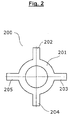
- connection means 200 is a ring-shaped metal foil 201 with four strip-shaped extensions 202, 203, 204 and 205.
- the connection means 200 corresponds in form and function to the connection means 110, 111 and 112, which in the in Fig. 1 illustrated electrochemical element 100 are installed.
- the outer and inner diameter of the ring 201 corresponds exactly to the outer and inner diameter of the in Fig. 1 shown single segments 103, 104, 105 and 106 of the first electrode 108. If such a connecting means in a cup-shaped housing 101, as in Fig. 1 shown, laid flat, so the strip-shaped extensions 202, 203, 204 and 205 buckle upwards. So are three such connection means, as in Fig.
- connection means 110 represented as connecting means 110, 111 and 112 disposed between the individual segments 103, 104, 105 and 106 , the strip-shaped extensions 202, 203, 204 and 205, the mentioned electrically conductive connection between the other contact surfaces 103c, 104c and 105c of the respective segments and the inside 101a of the housing 101 .
- the annular part 201 of the connection means 200 connects the segments 103, 104, 105 and 106 with each other.
Landscapes
- Chemical & Material Sciences (AREA)
- Chemical Kinetics & Catalysis (AREA)
- Electrochemistry (AREA)
- General Chemical & Material Sciences (AREA)
- Engineering & Computer Science (AREA)
- Materials Engineering (AREA)
- Manufacturing & Machinery (AREA)
- Connection Of Batteries Or Terminals (AREA)
- Primary Cells (AREA)
- Battery Electrode And Active Subsutance (AREA)
- Cell Electrode Carriers And Collectors (AREA)
Applications Claiming Priority (2)
| Application Number | Priority Date | Filing Date | Title |
|---|---|---|---|
| DE102009039945A DE102009039945A1 (de) | 2009-08-26 | 2009-08-26 | Elektrochemisches Element mit reduziertem Innenwiderstand |
| PCT/EP2010/059959 WO2011023447A1 (de) | 2009-08-26 | 2010-07-12 | Elektrochemisches element mit reduziertem innenwiderstand |
Publications (2)
| Publication Number | Publication Date |
|---|---|
| EP2471131A1 EP2471131A1 (de) | 2012-07-04 |
| EP2471131B1 true EP2471131B1 (de) | 2013-11-13 |
Family
ID=43063205
Family Applications (1)
| Application Number | Title | Priority Date | Filing Date |
|---|---|---|---|
| EP10732358.6A Active EP2471131B1 (de) | 2009-08-26 | 2010-07-12 | Elektrochemisches element mit reduziertem innenwiderstand |
Country Status (7)
| Country | Link |
|---|---|
| US (1) | US8673484B2 (enExample) |
| EP (1) | EP2471131B1 (enExample) |
| JP (1) | JP5563085B2 (enExample) |
| KR (1) | KR20120055685A (enExample) |
| CN (1) | CN102612770B (enExample) |
| DE (1) | DE102009039945A1 (enExample) |
| WO (1) | WO2011023447A1 (enExample) |
Families Citing this family (2)
| Publication number | Priority date | Publication date | Assignee | Title |
|---|---|---|---|---|
| DE102018218287A1 (de) * | 2018-10-25 | 2020-04-30 | Robert Bosch Gmbh | Batteriezelle |
| EP4553966A1 (de) | 2023-11-07 | 2025-05-14 | VARTA Microbattery GmbH | Elektrochemische energiespeicherzelle |
Family Cites Families (13)
| Publication number | Priority date | Publication date | Assignee | Title |
|---|---|---|---|---|
| US3738869A (en) * | 1972-05-25 | 1973-06-12 | Mallory & Co Inc P R | Electric cell with depolarizer compensated against current erosion effects |
| FR2316759A1 (fr) * | 1975-06-30 | 1977-01-28 | Accumulateurs Fixes | Generateur electrochimique cylindrique |
| JPS55120076U (enExample) * | 1979-02-16 | 1980-08-25 | ||
| DE3543425A1 (de) * | 1985-12-09 | 1987-06-11 | Varta Batterie | Galvanisches element mit einer negativen lithium-elektrode |
| JPS6324559A (ja) * | 1986-07-17 | 1988-02-01 | Fuji Elelctrochem Co Ltd | 筒型アルカリ電池 |
| JP2707638B2 (ja) * | 1988-10-07 | 1998-02-04 | 松下電器産業株式会社 | アルカリマンガン電池 |
| US5283139A (en) * | 1993-04-12 | 1994-02-01 | Duracell Inc. | Alkaline cell |
| JPH08287902A (ja) * | 1995-04-11 | 1996-11-01 | Matsushita Electric Ind Co Ltd | アルカリ乾電池 |
| US6521378B2 (en) * | 1997-08-01 | 2003-02-18 | Duracell Inc. | Electrode having multi-modal distribution of zinc-based particles |
| DE60034870T2 (de) | 1999-09-16 | 2008-01-17 | Matsushita Electric Industrial Co., Ltd., Kadoma | Abgedichtete zylindrische nickel-wasserstoffspeicherbatterie |
| US6472099B1 (en) * | 2000-06-13 | 2002-10-29 | The Gillette Company | Cathode indentations in alkaline cell |
| US20020172867A1 (en) * | 2001-04-10 | 2002-11-21 | Anglin David L. | Battery cathode |
| JP2006500742A (ja) * | 2002-09-20 | 2006-01-05 | エヴァレディー バッテリー カンパニー インコーポレイテッド | 電極界面表面積を増大させ、活物質を増加させたバッテリ |
-
2009
- 2009-08-26 DE DE102009039945A patent/DE102009039945A1/de not_active Withdrawn
-
2010
- 2010-07-12 CN CN201080037841.XA patent/CN102612770B/zh active Active
- 2010-07-12 KR KR1020127006633A patent/KR20120055685A/ko not_active Withdrawn
- 2010-07-12 WO PCT/EP2010/059959 patent/WO2011023447A1/de not_active Ceased
- 2010-07-12 US US13/390,547 patent/US8673484B2/en active Active
- 2010-07-12 EP EP10732358.6A patent/EP2471131B1/de active Active
- 2010-07-12 JP JP2012525953A patent/JP5563085B2/ja active Active
Also Published As
| Publication number | Publication date |
|---|---|
| KR20120055685A (ko) | 2012-05-31 |
| CN102612770B (zh) | 2014-10-29 |
| US8673484B2 (en) | 2014-03-18 |
| JP5563085B2 (ja) | 2014-07-30 |
| EP2471131A1 (de) | 2012-07-04 |
| US20120141865A1 (en) | 2012-06-07 |
| WO2011023447A1 (de) | 2011-03-03 |
| DE102009039945A1 (de) | 2011-03-03 |
| JP2013503420A (ja) | 2013-01-31 |
| CN102612770A (zh) | 2012-07-25 |
Similar Documents
| Publication | Publication Date | Title |
|---|---|---|
| EP2771922B1 (de) | Knopfzelle mit elektrodenwickel | |
| EP3371841B1 (de) | Dichtsystem für poldurchführung | |
| DE2803211A1 (de) | Elektrochemische zelle und kathode dafuer | |
| DE3420585A1 (de) | Bipolare metall-luftsauerstoffbatterie mit einer sich selbst erhaltenden anode | |
| EP1011163A1 (de) | Elektrischer Akkumulator in Form einer Knopfzelle | |
| DE4443688C1 (de) | Bipolarplatte für Brennstoffzellen | |
| DE69905574T2 (de) | Elektrochemische zelle mit grosser mündung an der gehäuseöffnung | |
| DE102012217478A1 (de) | Batteriezelle mit Stromabnehmer zur Gehäusekontaktierung | |
| DE112018000798T5 (de) | Blattfeder-kompressionssystemauslegung | |
| EP2471131B1 (de) | Elektrochemisches element mit reduziertem innenwiderstand | |
| EP3284119B1 (de) | Batterie mit prismatischem metallgehäuse | |
| DE102022107471B3 (de) | Batteriezelle und Verfahren zu ihrer Herstellung | |
| EP2606519A1 (de) | Metall-luft-zelle mit hoher kapazität | |
| DE102022103728B3 (de) | Batteriezelle | |
| DE2527783A1 (de) | Silber(ii)oxid-zelle, deren entladung bei 1 potentialwert erfolgt | |
| DE102016215666A1 (de) | Elektrodenanordnung für Lithium-basierte galvanische Zellen und Verfahren zu deren Herstellung | |
| EP2978041B1 (de) | Batterie mit flüssigem Elektrolyten und Herstellungsverfahren | |
| EP3082179B1 (de) | Batterie mit pneumo-elektrischem sicherheitsschalter | |
| WO2022248253A1 (de) | Batteriezelle | |
| DE102015207069A1 (de) | Batterie mit prismatischem Metallgehäuse | |
| EP3276700B1 (de) | Elektrochemische zelle | |
| DE102015201662A1 (de) | Galvanische Zelle mit flächiger Ableiteranordnung | |
| EP2833449B1 (de) | Elektrochemische Zelle mit einer als Hohlzylinder ausgebildeten positiven und einer darin angeordneten negativen Elektrode | |
| DE102021111378A1 (de) | Elektrodenstapel für eine Batteriezelle, Batteriezelle und Verfahren zur Herstellung | |
| EP4465393A1 (de) | Elektrochemische knopfzelle und verfahren zur herstellung |
Legal Events
| Date | Code | Title | Description |
|---|---|---|---|
| PUAI | Public reference made under article 153(3) epc to a published international application that has entered the european phase |
Free format text: ORIGINAL CODE: 0009012 |
|
| 17P | Request for examination filed |
Effective date: 20120202 |
|
| AK | Designated contracting states |
Kind code of ref document: A1 Designated state(s): AL AT BE BG CH CY CZ DE DK EE ES FI FR GB GR HR HU IE IS IT LI LT LU LV MC MK MT NL NO PL PT RO SE SI SK SM TR |
|
| DAX | Request for extension of the european patent (deleted) | ||
| GRAP | Despatch of communication of intention to grant a patent |
Free format text: ORIGINAL CODE: EPIDOSNIGR1 |
|
| INTG | Intention to grant announced |
Effective date: 20130704 |
|
| GRAS | Grant fee paid |
Free format text: ORIGINAL CODE: EPIDOSNIGR3 |
|
| GRAA | (expected) grant |
Free format text: ORIGINAL CODE: 0009210 |
|
| AK | Designated contracting states |
Kind code of ref document: B1 Designated state(s): AL AT BE BG CH CY CZ DE DK EE ES FI FR GB GR HR HU IE IS IT LI LT LU LV MC MK MT NL NO PL PT RO SE SI SK SM TR |
|
| REG | Reference to a national code |
Ref country code: GB Ref legal event code: FG4D Free format text: NOT ENGLISH |
|
| REG | Reference to a national code |
Ref country code: CH Ref legal event code: EP |
|
| REG | Reference to a national code |
Ref country code: AT Ref legal event code: REF Ref document number: 640913 Country of ref document: AT Kind code of ref document: T Effective date: 20131215 |
|
| REG | Reference to a national code |
Ref country code: IE Ref legal event code: FG4D Free format text: LANGUAGE OF EP DOCUMENT: GERMAN |
|
| REG | Reference to a national code |
Ref country code: DE Ref legal event code: R096 Ref document number: 502010005378 Country of ref document: DE Effective date: 20140109 |
|
| REG | Reference to a national code |
Ref country code: NL Ref legal event code: VDEP Effective date: 20131113 |
|
| REG | Reference to a national code |
Ref country code: LT Ref legal event code: MG4D |
|
| PG25 | Lapsed in a contracting state [announced via postgrant information from national office to epo] |
Ref country code: HR Free format text: LAPSE BECAUSE OF FAILURE TO SUBMIT A TRANSLATION OF THE DESCRIPTION OR TO PAY THE FEE WITHIN THE PRESCRIBED TIME-LIMIT Effective date: 20131113 Ref country code: IS Free format text: LAPSE BECAUSE OF FAILURE TO SUBMIT A TRANSLATION OF THE DESCRIPTION OR TO PAY THE FEE WITHIN THE PRESCRIBED TIME-LIMIT Effective date: 20140313 Ref country code: NO Free format text: LAPSE BECAUSE OF FAILURE TO SUBMIT A TRANSLATION OF THE DESCRIPTION OR TO PAY THE FEE WITHIN THE PRESCRIBED TIME-LIMIT Effective date: 20140213 Ref country code: LT Free format text: LAPSE BECAUSE OF FAILURE TO SUBMIT A TRANSLATION OF THE DESCRIPTION OR TO PAY THE FEE WITHIN THE PRESCRIBED TIME-LIMIT Effective date: 20131113 Ref country code: FI Free format text: LAPSE BECAUSE OF FAILURE TO SUBMIT A TRANSLATION OF THE DESCRIPTION OR TO PAY THE FEE WITHIN THE PRESCRIBED TIME-LIMIT Effective date: 20131113 Ref country code: SE Free format text: LAPSE BECAUSE OF FAILURE TO SUBMIT A TRANSLATION OF THE DESCRIPTION OR TO PAY THE FEE WITHIN THE PRESCRIBED TIME-LIMIT Effective date: 20131113 Ref country code: NL Free format text: LAPSE BECAUSE OF FAILURE TO SUBMIT A TRANSLATION OF THE DESCRIPTION OR TO PAY THE FEE WITHIN THE PRESCRIBED TIME-LIMIT Effective date: 20131113 |
|
| PG25 | Lapsed in a contracting state [announced via postgrant information from national office to epo] |
Ref country code: CY Free format text: LAPSE BECAUSE OF FAILURE TO SUBMIT A TRANSLATION OF THE DESCRIPTION OR TO PAY THE FEE WITHIN THE PRESCRIBED TIME-LIMIT Effective date: 20131113 Ref country code: ES Free format text: LAPSE BECAUSE OF FAILURE TO SUBMIT A TRANSLATION OF THE DESCRIPTION OR TO PAY THE FEE WITHIN THE PRESCRIBED TIME-LIMIT Effective date: 20131113 Ref country code: LV Free format text: LAPSE BECAUSE OF FAILURE TO SUBMIT A TRANSLATION OF THE DESCRIPTION OR TO PAY THE FEE WITHIN THE PRESCRIBED TIME-LIMIT Effective date: 20131113 |
|
| PG25 | Lapsed in a contracting state [announced via postgrant information from national office to epo] |
Ref country code: PT Free format text: LAPSE BECAUSE OF FAILURE TO SUBMIT A TRANSLATION OF THE DESCRIPTION OR TO PAY THE FEE WITHIN THE PRESCRIBED TIME-LIMIT Effective date: 20140313 |
|
| PG25 | Lapsed in a contracting state [announced via postgrant information from national office to epo] |
Ref country code: EE Free format text: LAPSE BECAUSE OF FAILURE TO SUBMIT A TRANSLATION OF THE DESCRIPTION OR TO PAY THE FEE WITHIN THE PRESCRIBED TIME-LIMIT Effective date: 20131113 |
|
| REG | Reference to a national code |
Ref country code: DE Ref legal event code: R097 Ref document number: 502010005378 Country of ref document: DE |
|
| PG25 | Lapsed in a contracting state [announced via postgrant information from national office to epo] |
Ref country code: CZ Free format text: LAPSE BECAUSE OF FAILURE TO SUBMIT A TRANSLATION OF THE DESCRIPTION OR TO PAY THE FEE WITHIN THE PRESCRIBED TIME-LIMIT Effective date: 20131113 Ref country code: SK Free format text: LAPSE BECAUSE OF FAILURE TO SUBMIT A TRANSLATION OF THE DESCRIPTION OR TO PAY THE FEE WITHIN THE PRESCRIBED TIME-LIMIT Effective date: 20131113 Ref country code: PL Free format text: LAPSE BECAUSE OF FAILURE TO SUBMIT A TRANSLATION OF THE DESCRIPTION OR TO PAY THE FEE WITHIN THE PRESCRIBED TIME-LIMIT Effective date: 20131113 Ref country code: RO Free format text: LAPSE BECAUSE OF FAILURE TO SUBMIT A TRANSLATION OF THE DESCRIPTION OR TO PAY THE FEE WITHIN THE PRESCRIBED TIME-LIMIT Effective date: 20131113 |
|
| PLBE | No opposition filed within time limit |
Free format text: ORIGINAL CODE: 0009261 |
|
| STAA | Information on the status of an ep patent application or granted ep patent |
Free format text: STATUS: NO OPPOSITION FILED WITHIN TIME LIMIT |
|
| PG25 | Lapsed in a contracting state [announced via postgrant information from national office to epo] |
Ref country code: DK Free format text: LAPSE BECAUSE OF FAILURE TO SUBMIT A TRANSLATION OF THE DESCRIPTION OR TO PAY THE FEE WITHIN THE PRESCRIBED TIME-LIMIT Effective date: 20131113 |
|
| 26N | No opposition filed |
Effective date: 20140814 |
|
| REG | Reference to a national code |
Ref country code: DE Ref legal event code: R097 Ref document number: 502010005378 Country of ref document: DE Effective date: 20140814 |
|
| PG25 | Lapsed in a contracting state [announced via postgrant information from national office to epo] |
Ref country code: SI Free format text: LAPSE BECAUSE OF FAILURE TO SUBMIT A TRANSLATION OF THE DESCRIPTION OR TO PAY THE FEE WITHIN THE PRESCRIBED TIME-LIMIT Effective date: 20131113 Ref country code: LU Free format text: LAPSE BECAUSE OF FAILURE TO SUBMIT A TRANSLATION OF THE DESCRIPTION OR TO PAY THE FEE WITHIN THE PRESCRIBED TIME-LIMIT Effective date: 20140712 |
|
| REG | Reference to a national code |
Ref country code: CH Ref legal event code: PL |
|
| REG | Reference to a national code |
Ref country code: IE Ref legal event code: MM4A |
|
| PG25 | Lapsed in a contracting state [announced via postgrant information from national office to epo] |
Ref country code: IT Free format text: LAPSE BECAUSE OF FAILURE TO SUBMIT A TRANSLATION OF THE DESCRIPTION OR TO PAY THE FEE WITHIN THE PRESCRIBED TIME-LIMIT Effective date: 20131113 Ref country code: CH Free format text: LAPSE BECAUSE OF NON-PAYMENT OF DUE FEES Effective date: 20140731 Ref country code: LI Free format text: LAPSE BECAUSE OF NON-PAYMENT OF DUE FEES Effective date: 20140731 |
|
| PG25 | Lapsed in a contracting state [announced via postgrant information from national office to epo] |
Ref country code: IE Free format text: LAPSE BECAUSE OF NON-PAYMENT OF DUE FEES Effective date: 20140712 |
|
| REG | Reference to a national code |
Ref country code: DE Ref legal event code: R082 Ref document number: 502010005378 Country of ref document: DE Representative=s name: OSTERTAG & PARTNER, PATENTANWAELTE MBB, DE Ref country code: DE Ref legal event code: R082 Ref document number: 502010005378 Country of ref document: DE Representative=s name: PATENTANWALTSKANZLEI CARTAGENA PARTNERSCHAFTSG, DE |
|
| PG25 | Lapsed in a contracting state [announced via postgrant information from national office to epo] |
Ref country code: MC Free format text: LAPSE BECAUSE OF FAILURE TO SUBMIT A TRANSLATION OF THE DESCRIPTION OR TO PAY THE FEE WITHIN THE PRESCRIBED TIME-LIMIT Effective date: 20131113 Ref country code: SM Free format text: LAPSE BECAUSE OF FAILURE TO SUBMIT A TRANSLATION OF THE DESCRIPTION OR TO PAY THE FEE WITHIN THE PRESCRIBED TIME-LIMIT Effective date: 20131113 |
|
| PG25 | Lapsed in a contracting state [announced via postgrant information from national office to epo] |
Ref country code: BG Free format text: LAPSE BECAUSE OF FAILURE TO SUBMIT A TRANSLATION OF THE DESCRIPTION OR TO PAY THE FEE WITHIN THE PRESCRIBED TIME-LIMIT Effective date: 20131113 Ref country code: MT Free format text: LAPSE BECAUSE OF FAILURE TO SUBMIT A TRANSLATION OF THE DESCRIPTION OR TO PAY THE FEE WITHIN THE PRESCRIBED TIME-LIMIT Effective date: 20131113 Ref country code: GR Free format text: LAPSE BECAUSE OF FAILURE TO SUBMIT A TRANSLATION OF THE DESCRIPTION OR TO PAY THE FEE WITHIN THE PRESCRIBED TIME-LIMIT Effective date: 20140214 |
|
| REG | Reference to a national code |
Ref country code: FR Ref legal event code: PLFP Year of fee payment: 7 |
|
| PG25 | Lapsed in a contracting state [announced via postgrant information from national office to epo] |
Ref country code: TR Free format text: LAPSE BECAUSE OF FAILURE TO SUBMIT A TRANSLATION OF THE DESCRIPTION OR TO PAY THE FEE WITHIN THE PRESCRIBED TIME-LIMIT Effective date: 20131113 Ref country code: HU Free format text: LAPSE BECAUSE OF FAILURE TO SUBMIT A TRANSLATION OF THE DESCRIPTION OR TO PAY THE FEE WITHIN THE PRESCRIBED TIME-LIMIT; INVALID AB INITIO Effective date: 20100712 Ref country code: BE Free format text: LAPSE BECAUSE OF FAILURE TO SUBMIT A TRANSLATION OF THE DESCRIPTION OR TO PAY THE FEE WITHIN THE PRESCRIBED TIME-LIMIT Effective date: 20140731 |
|
| REG | Reference to a national code |
Ref country code: AT Ref legal event code: MM01 Ref document number: 640913 Country of ref document: AT Kind code of ref document: T Effective date: 20150712 |
|
| PG25 | Lapsed in a contracting state [announced via postgrant information from national office to epo] |
Ref country code: AT Free format text: LAPSE BECAUSE OF NON-PAYMENT OF DUE FEES Effective date: 20150712 |
|
| REG | Reference to a national code |
Ref country code: FR Ref legal event code: PLFP Year of fee payment: 8 |
|
| PG25 | Lapsed in a contracting state [announced via postgrant information from national office to epo] |
Ref country code: MK Free format text: LAPSE BECAUSE OF FAILURE TO SUBMIT A TRANSLATION OF THE DESCRIPTION OR TO PAY THE FEE WITHIN THE PRESCRIBED TIME-LIMIT Effective date: 20131113 |
|
| REG | Reference to a national code |
Ref country code: FR Ref legal event code: PLFP Year of fee payment: 9 |
|
| PG25 | Lapsed in a contracting state [announced via postgrant information from national office to epo] |
Ref country code: AL Free format text: LAPSE BECAUSE OF FAILURE TO SUBMIT A TRANSLATION OF THE DESCRIPTION OR TO PAY THE FEE WITHIN THE PRESCRIBED TIME-LIMIT Effective date: 20131113 |
|
| REG | Reference to a national code |
Ref country code: DE Ref legal event code: R082 Ref document number: 502010005378 Country of ref document: DE Representative=s name: OSTERTAG & PARTNER, PATENTANWAELTE MBB, DE |
|
| P01 | Opt-out of the competence of the unified patent court (upc) registered |
Effective date: 20230526 |
|
| PGFP | Annual fee paid to national office [announced via postgrant information from national office to epo] |
Ref country code: DE Payment date: 20240723 Year of fee payment: 15 |
|
| PGFP | Annual fee paid to national office [announced via postgrant information from national office to epo] |
Ref country code: GB Payment date: 20240723 Year of fee payment: 15 |
|
| PGFP | Annual fee paid to national office [announced via postgrant information from national office to epo] |
Ref country code: FR Payment date: 20240724 Year of fee payment: 15 |