EP2471131B1 - Elektrochemisches element mit reduziertem innenwiderstand - Google Patents
Elektrochemisches element mit reduziertem innenwiderstand Download PDFInfo
- Publication number
- EP2471131B1 EP2471131B1 EP10732358.6A EP10732358A EP2471131B1 EP 2471131 B1 EP2471131 B1 EP 2471131B1 EP 10732358 A EP10732358 A EP 10732358A EP 2471131 B1 EP2471131 B1 EP 2471131B1
- Authority
- EP
- European Patent Office
- Prior art keywords
- electrode
- electrochemical element
- element according
- housing
- segments
- Prior art date
- Legal status (The legal status is an assumption and is not a legal conclusion. Google has not performed a legal analysis and makes no representation as to the accuracy of the status listed.)
- Active
Links
- 229910052751 metal Inorganic materials 0.000 claims description 7
- 239000002184 metal Substances 0.000 claims description 7
- NUJOXMJBOLGQSY-UHFFFAOYSA-N manganese dioxide Chemical compound O=[Mn]=O NUJOXMJBOLGQSY-UHFFFAOYSA-N 0.000 claims description 6
- HCHKCACWOHOZIP-UHFFFAOYSA-N Zinc Chemical compound [Zn] HCHKCACWOHOZIP-UHFFFAOYSA-N 0.000 claims description 3
- 239000011888 foil Substances 0.000 claims description 3
- 239000011701 zinc Substances 0.000 claims description 3
- 229910052725 zinc Inorganic materials 0.000 claims description 3
- 238000010276 construction Methods 0.000 claims 1
- 230000000284 resting effect Effects 0.000 claims 1
- 239000003792 electrolyte Substances 0.000 description 3
- 229910052748 manganese Inorganic materials 0.000 description 3
- 239000011572 manganese Substances 0.000 description 3
- 239000000463 material Substances 0.000 description 3
- 239000007767 bonding agent Substances 0.000 description 2
- 239000000203 mixture Substances 0.000 description 2
- 230000008092 positive effect Effects 0.000 description 2
- 241001397173 Kali <angiosperm> Species 0.000 description 1
- PWHULOQIROXLJO-UHFFFAOYSA-N Manganese Chemical compound [Mn] PWHULOQIROXLJO-UHFFFAOYSA-N 0.000 description 1
- KWYUFKZDYYNOTN-UHFFFAOYSA-M Potassium hydroxide Chemical compound [OH-].[K+] KWYUFKZDYYNOTN-UHFFFAOYSA-M 0.000 description 1
- 229910001297 Zn alloy Inorganic materials 0.000 description 1
- 239000006229 carbon black Substances 0.000 description 1
- 239000004020 conductor Substances 0.000 description 1
- 230000001419 dependent effect Effects 0.000 description 1
- 230000000694 effects Effects 0.000 description 1
- 239000003349 gelling agent Substances 0.000 description 1
- 230000037431 insertion Effects 0.000 description 1
- 238000003780 insertion Methods 0.000 description 1
- 230000037427 ion transport Effects 0.000 description 1
- 239000000843 powder Substances 0.000 description 1
- 230000009467 reduction Effects 0.000 description 1
- 150000003752 zinc compounds Chemical class 0.000 description 1
Images

Classifications
-
- H—ELECTRICITY
- H01—ELECTRIC ELEMENTS
- H01M—PROCESSES OR MEANS, e.g. BATTERIES, FOR THE DIRECT CONVERSION OF CHEMICAL ENERGY INTO ELECTRICAL ENERGY
- H01M4/00—Electrodes
- H01M4/02—Electrodes composed of, or comprising, active material
- H01M4/06—Electrodes for primary cells
-
- H—ELECTRICITY
- H01—ELECTRIC ELEMENTS
- H01M—PROCESSES OR MEANS, e.g. BATTERIES, FOR THE DIRECT CONVERSION OF CHEMICAL ENERGY INTO ELECTRICAL ENERGY
- H01M4/00—Electrodes
- H01M4/02—Electrodes composed of, or comprising, active material
- H01M4/64—Carriers or collectors
- H01M4/66—Selection of materials
- H01M4/661—Metal or alloys, e.g. alloy coatings
-
- H—ELECTRICITY
- H01—ELECTRIC ELEMENTS
- H01M—PROCESSES OR MEANS, e.g. BATTERIES, FOR THE DIRECT CONVERSION OF CHEMICAL ENERGY INTO ELECTRICAL ENERGY
- H01M4/00—Electrodes
- H01M4/02—Electrodes composed of, or comprising, active material
- H01M4/64—Carriers or collectors
- H01M4/66—Selection of materials
- H01M4/663—Selection of materials containing carbon or carbonaceous materials as conductive part, e.g. graphite, carbon fibres
-
- H—ELECTRICITY
- H01—ELECTRIC ELEMENTS
- H01M—PROCESSES OR MEANS, e.g. BATTERIES, FOR THE DIRECT CONVERSION OF CHEMICAL ENERGY INTO ELECTRICAL ENERGY
- H01M6/00—Primary cells; Manufacture thereof
- H01M6/04—Cells with aqueous electrolyte
- H01M6/06—Dry cells, i.e. cells wherein the electrolyte is rendered non-fluid
- H01M6/08—Dry cells, i.e. cells wherein the electrolyte is rendered non-fluid with cup-shaped electrodes
- H01M6/085—Dry cells, i.e. cells wherein the electrolyte is rendered non-fluid with cup-shaped electrodes of the reversed type, i.e. anode in the centre
-
- Y—GENERAL TAGGING OF NEW TECHNOLOGICAL DEVELOPMENTS; GENERAL TAGGING OF CROSS-SECTIONAL TECHNOLOGIES SPANNING OVER SEVERAL SECTIONS OF THE IPC; TECHNICAL SUBJECTS COVERED BY FORMER USPC CROSS-REFERENCE ART COLLECTIONS [XRACs] AND DIGESTS
- Y02—TECHNOLOGIES OR APPLICATIONS FOR MITIGATION OR ADAPTATION AGAINST CLIMATE CHANGE
- Y02P—CLIMATE CHANGE MITIGATION TECHNOLOGIES IN THE PRODUCTION OR PROCESSING OF GOODS
- Y02P70/00—Climate change mitigation technologies in the production process for final industrial or consumer products
- Y02P70/50—Manufacturing or production processes characterised by the final manufactured product
Definitions
- the present invention relates to an electrochemical element having a housing, two electrodes, one of which bears against the inside of the housing and defines a cavity in which the other is arranged, and a separator arranged between the electrodes.
- Cells of this type are often so-called alkali-manganese batteries, ie cells with a positive electrode of manganese dioxide (MnO 2 ) and a negative electrode of zinc and an alkaline electrolyte, the latter in particular based on potassium hydroxide (KOH).
- the positive electrode is designed as a hollow cylinder, the outside of which contacts the inside of a cup-shaped cell housing. Inside the positive electrode is disposed the negative electrode and also a separator to physically separate the positive electrode from the negative electrode while allowing ion transport between the two electrodes.
- the negative electrode is usually formed by mixing the active zinc compound in the form of a zinc alloy powder with the alkaline electrolyte and a gelling agent. The mixture is distributed in the cavity formed inside the positive electrode, or the cavity is filled with the mixture. Subsequently, a collector assembly is inserted into the open end of the cup-shaped cell housing. The negative electrode is preferably contacted via a pin-shaped collector, which is pressed upon insertion of the collector assembly in the cavity or in the negative electrode located therein. Finally, the cell housing is sealed, typically by placing a cover over the collector assembly. To seal the cell, The walls of the cell housing can be folded over this cover.
- the positive electrode formed as a hollow cylinder is usually not integrally incorporated into the cup-shaped cell housing, but in the form of individual segments, which then form the positive electrode.
- a disc-shaped segment can be inserted into a cylindrical cup-shaped cell housing, on which subsequently a plurality of annular segments are stacked.
- the inner diameter of the annular segments determines the volume and diameter of the cavity for the negative electrode.
- the outer diameter of both the disk-shaped and the annular segments are usually matched exactly to the corresponding inner diameter of the cup-shaped cell housing.
- electrochemical cells of the type described have a very high capacity. Common to them on the other hand but also a relatively high internal resistance, resulting in poor discharge properties can result. In particular, for pulse-shaped discharge profiles and for discharges under high current densities, the cells described are not optimally designed, which is why they are not or only partially suitable for many applications.
- the WO 01/97302 A2 is concerned with improving the current carrying capacity of al kali manganese batteries. This is to be achieved in that the cathodes are formed in a very specific geometry, namely they have to the inner cavity towards elongated bulges, which have the purpose to increase the contact areas between the anode and cathode. In addition, ring-shaped or disk-like connecting pieces can be arranged between individual cathode segments as cathode current collectors.
- a layer of a conductive material between a hollow cylindrical arranged within a housing to introduce positive electrode and the inner wall of the housing is carbon black.
- An electrochemical element according to the invention like the generic electrochemical elements described above, always comprises a housing having an inner side, a first electrode abutting the inside of the housing, which at the same time defines a cavity and a second electrode of opposite polarity, which is arranged inside this cavity.
- an inventive electrochemical element always has a separator which is arranged between the first and the second electrode.
- the first electrode is composed at least of at least two, preferably three or more individual segments. These borders on the one hand via first contact surfaces flat against each other and are on the other hand over other contact surfaces flat on the inside of the housing.
- the second electrode usually fills the cavity in the interior of the first electrode substantially completely. Your contacting can be done for example via a pin-shaped collector, as described above.
- the electrochemical element according to the invention is characterized in that between the first contact surfaces of the at least two individual segments, over which the individual segments adjoin one another flat, at least one connecting means is arranged, which connects the segments electrically conductive.
- An electrochemical element according to the invention is preferably a commercially available battery.
- the housing of an electrochemical element is preferably formed substantially cylindrical.
- Housing of an electrochemical element according to the invention particularly preferably has a standardized size such as, for example, AA (Mignon), AAA (Micro), C (Baby) or D (Mono).
- the first electrode may comprise, for example, a disc-shaped and one or more annular individual segments, preferably each with the same outer diameter. If, for example, one inserts the disc-shaped individual segment into the bottom of a cup-shaped, substantially cylindrically shaped housing and stacks one or more of the annular individual segments, this gives - a suitable outside diameter Assuming the annular segments - the aforementioned applied to the inside of the housing first electrode together with the cavity in which the second electrode is arranged. The volume or the dimensions of the cavity are determined by the dimensions and the number of annular individual segments (in particular by their inner diameter).
- An electrochemical element according to the invention preferably comprises two or more of the already mentioned annular individual segments, each with the same outside and inside diameter. Particularly preferably, it has a first electrode which consists of these two or more annular individual segments.
- the at least one connecting means is then arranged in each case between adjacent segments, so that adjacent segments are in each case conductively connected to one another via the at least one connecting means.
- the formed as a hollow cylinder part of the first electrode or the first electrode as a whole consist correspondingly particularly preferably of a plurality of stacked present annular individual segments each having the same outer and inner diameter. Consequently, it is also preferred that the cavity within the first electrode, which is formed by the stacked present individual segments, is formed substantially cylindrical.
- the annular individual segments preferably have a small height compared to their outer diameter.
- they are preferably the end faces of the segments.
- the size of the contact surfaces is correspondingly preferably defined by the outer and inner diameters of the annular individual segments.
- an electrochemical element according to the invention preferably comprises a connecting means of a material which has a higher electrical conductivity than the material from which the first electrode is made.
- Particularly suitable are connecting means made of metal, in particular of a metal foil or a metal sheet.
- the at least one connecting means does not extend only to the area between the contact surfaces of the segments of the first electrode of an electrochemical element according to the invention. Instead, it extends into the contact area between the other contact surfaces of the segments and the inside of the housing and thus connects the segments not only electrically conductive with each other, but also with the housing.
- the at least one connecting means is annular, in particular its outer and / or inner diameter preferably corresponds to the outer and / or inner diameter of the annular individual segments used. It thus optimally fills the contact area between the individual segments in preferred embodiments. Furthermore, it comprises at least one preferably strip-shaped extension, which is integrally formed on the outside of the ring.
- the first electrode of an electrochemical element according to the invention is preferably the positive electrode.
- the second electrode of an electrochemical element according to the invention is preferably the negative electrode.
- the positive electrode is a manganese dioxide electrode.
- the negative electrode is particularly preferably a zinc electrode.
- the electrochemical element according to the invention is in particular an alkali-manganese cell. As such, of course, it preferably also has a corresponding alkaline electrolyte.
- a preferred embodiment of an electrochemical element 100 according to the invention is shown schematically.
- the electrochemical element 100 is shown partly in cross-section (right), partly in an uncut view with hidden edges (left) shown. It has on the one hand a cup-shaped housing 101 with a substantially cylindrical shell and a substantially planar, circular bottom portion.
- On the inside 101a of the housing is formed as a hollow cylinder formed first electrode 102 , which is composed of the individual segments 103, 104, 105 and 106 . These individual segments are each ring-shaped and each have an identical outer and inner diameter.
- Within the housing 101 they are stacked and define in their center the cavity 107.
- the negative electrode 108 is arranged, which in turn is surrounded by a cup-shaped separator 109 which separates the electrodes 102 and 108 from each other.
- the mentioned individual segments 103, 104, 105 and 106 adjoin one another via first contact surfaces 103a, 104b, 104a, 105b, 105a and 106b (the respective end faces of adjacent segments). Via further contact surfaces 103c, 104c, 105c and 106c (the respective lateral surfaces of the annular individual segments 103, 104, 105 and 106) , they adjoin the inside 101a of the housing 101 in a planar manner .
- a connecting means (110, 111 and 112) is arranged, which connects the segments 103, 104, 105 and 106 electrically conductively.
- this connection means not only covers the area between the first contact surfaces 103a, 104b, 104a, 105b, 105a and 106b , but also extends into the contact area between the further contact surfaces 103c, 104c and 105c of the respective segments and the inside of the housing 101 and thus connects both the individual segments 103, 104, 105 and 106 with each other and the segments 103, 104 and 105 with the housing 101.
- the cup-shaped housing 101 thus forms a pole of the electrochemical element 100 .
- the other pole 113 can be found on the open side of the housing cup 101. From this, the pin-shaped arrester 114 protrudes into the cavity 107 in the interior of the first electrode 102 and thereby contacts the second electrode 108 arranged therein. Via the cover 114, which contacts the pole 113 simultaneously isolated from the housing 101 , the open end of the housing cup 101 is sealed.
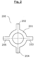
- connection means 200 is a ring-shaped metal foil 201 with four strip-shaped extensions 202, 203, 204 and 205.
- the connection means 200 corresponds in form and function to the connection means 110, 111 and 112, which in the in Fig. 1 illustrated electrochemical element 100 are installed.
- the outer and inner diameter of the ring 201 corresponds exactly to the outer and inner diameter of the in Fig. 1 shown single segments 103, 104, 105 and 106 of the first electrode 108. If such a connecting means in a cup-shaped housing 101, as in Fig. 1 shown, laid flat, so the strip-shaped extensions 202, 203, 204 and 205 buckle upwards. So are three such connection means, as in Fig.
- connection means 110 represented as connecting means 110, 111 and 112 disposed between the individual segments 103, 104, 105 and 106 , the strip-shaped extensions 202, 203, 204 and 205, the mentioned electrically conductive connection between the other contact surfaces 103c, 104c and 105c of the respective segments and the inside 101a of the housing 101 .
- the annular part 201 of the connection means 200 connects the segments 103, 104, 105 and 106 with each other.
Landscapes
- Chemical & Material Sciences (AREA)
- Chemical Kinetics & Catalysis (AREA)
- Electrochemistry (AREA)
- General Chemical & Material Sciences (AREA)
- Engineering & Computer Science (AREA)
- Materials Engineering (AREA)
- Manufacturing & Machinery (AREA)
- Connection Of Batteries Or Terminals (AREA)
- Primary Cells (AREA)
- Battery Electrode And Active Subsutance (AREA)
- Cell Electrode Carriers And Collectors (AREA)
Description
- Die vorliegende Erfindung betrifft ein elektrochemisches Element mit einem Gehäuse, zwei Elektroden, von denen eine an der Innenseite des Gehäuses anliegt und einen Hohlraum definiert, in dem die andere angeordnet ist, sowie einem zwischen den Elektroden angeordneten Separator.
- Bei Zellen dieser Bauart handelt es sich häufig um sogenannte Alkali-Mangan-Batterien, also um Zellen mit einer positiven Elektrode aus Mangandioxid (MnO2) und einer negativen Elektrode aus Zink sowie einem alkalischen Elektrolyten, letzterer insbesondere auf Basis von Kaliumhydroxid (KOH). In der Regel ist die positive Elektrode als Hohlzylinder ausgebildet, dessen Außenseite die Innenseite eines becherförmigen Zellengehäuses kontaktiert. Im Inneren der positiven Elektrode ist die negative Elektrode angeordnet und außerdem ein Separator, um die positive Elektrode physikalisch von der negativen Elektrode zu trennen und dabei einen Ionentransport zwischen den beiden Elektroden zuzulassen.
- Die negative Elektrode wird in der Regel ausgebildet, indem die aktive Zinkmasse in Form eines Zinklegierungspulvers mit dem alkalischen Elektrolyten und einem Geliermittel vermischt wird. Das Gemisch wird in dem im Inneren der positiven Elektrode ausgebildeten Hohlraum verteilt, bzw. der Hohlraum wird mit dem Gemisch befüllt. Anschließend wird eine Kollektorenbaugruppe in das offenen Ende des becherförmigen Zellengehäuses eingesetzt. Die negative Elektrode wird dabei bevorzugt über einen stiftförmigen Kollektor kontaktiert, der beim Einsetzen der Kollektorbaugruppe in den Hohlraum bzw. in die sich darin befindliche negative Elektrode gepresst wird. Abschließend wird das Zellengehäuse verschlossen, in der Regel durch Einbringen einer Abdeckung, die über der Kollektorbaugruppe angebracht wird. Um die Zelle abzudichten, können die Wände des Zellengehäuses über diese Abdeckung umgefalzt werden.
- Insbesondere aus produktionstechnischen Gründen wird die als Hohlzylinder ausgebildete positive Elektrode in aller Regel nicht einstückig in das becherförmige Zellengehäuse eingebracht, sondern in Form von einzelnen Segmenten, die zusammengesetzt dann die positive Elektrode bilden. Beispielsweise kann ein scheibenförmiges Segment in ein zylindrisches becherförmiges Zellengehäuse eingelegt werden, auf das anschließend mehrere ringförmige Segmente gestapelt werden. Der Innendurchmesser der ringförmigen Segmente bestimmt dann das Volumen und den Durchmesser des Hohlraums für die negative Elektrode. Die Außendurchmesser sowohl des scheibenförmigen als auch der ringförmigen Segmente sind in der Regel exakt auf den entsprechenden Innendurchmesser des becherförmigen Zellengehäuses abgestimmt.
- Naturgemäß haben elektrochemische Zellen der beschriebenen Bauart eine sehr hohe Kapazität. Gemein ist ihnen auf der anderen Seite aber auch ein relativ hoher Innenwiderstand, woraus schlechte Entladeeigenschaften resultieren können. Insbesondere für pulsförmige Entladeprofile und für Entladungen unter hohen Stromdichten sind die beschriebenen Zellen nicht optimal ausgelegt, weswegen sie für viele Anwendungszwecke nicht oder nur bedingt geeignet sind.
- Die
WO 01/97302 A2 - Aus der
WO 02/084766 - Der vorliegenden Erfindung lag die Aufgabe zugrunde, die Entladeeigenschaften der eingangs erwähnten gattungsgemäßen elektrochemischen Elemente zu verbessern und so ihr potenzielles Anwendungsspektrum zu erweitern.
- Diese Aufgabe wird gelöst durch das elektrochemische Element mit den Merkmalen des Anspruchs 1. Bevorzugte Ausführungsformen des erfindungsgemäßen elektrochemischen Elements finden sich in den abhängigen Ansprüchen 2 bis 13. Der Wortlaut sämtlicher Ansprüche wird hiermit mit durch Bezugnahme zum Inhalt dieser Beschreibung gemacht.
- Ein erfindungsgemäßes elektrochemisches Element umfasst wie die eingangs beschriebenen gattungsgemäßen elektrochemischen Elemente stets ein Gehäuse mit einer Innenseite, eine an der Innenseite des Gehäuses anliegende erste Elektrode, die zugleich einen Hohlraum definiert und eine zweite Elektrode entgegengesetzter Polarität, die innerhalb dieses Hohlraums angeordnet ist. Daneben weist ein erfindungsgemäßes elektrochemisches Element stets einen Separator auf, der zwischen der ersten und der zweiten Elektrode angeordnet ist.
- Die erste Elektrode setzt sich dabei zumindest aus mindestens zwei, vorzugsweise aus drei oder mehr Einzelsegmenten zusammen. Diese grenzen zum einen über erste Kontaktflächen flächig aneinander und liegen zum anderen über weitere Kontaktflächen flächig an der Innenseite des Gehäuses an.
- Die zweite Elektrode füllt den Hohlraum im Inneren der ersten Elektrode in der Regel im wesentlich vollständig aus. Ihre Kontaktierung kann beispielsweise über einen stiftförmigen Kollektor erfolgen, wie er eingangs beschrieben wurde.
- Besonders zeichnet sich das erfindungsgemäße elektrochemische Element dadurch aus, dass zwischen den ersten Kontaktflächen der mindestens zwei Einzelsegmente, über die die Einzelsegmente flächig aneinandergrenzen, mindestens ein Verbindungsmittel angeordnet ist, das die Segmente elektrisch leitend verbindet.
- Überraschenderweise wurde festgestellt, das durch die Anordnung eines solchen mindestens einen Verbindungsmittels zwischen den Segmenten der Innenwiderstand von elektrochemischen Elementen der oben beschriebenen Bauart drastisch reduziert werden konnte. Teilweise konnten Rückgänge des Innenwiderstandes um deutlich mehr als die Hälfte gemessen werden, was sich natürlich positiv auf das potenzielle Anwendungsspektrum des erfindungsgemäßen elektrochemischen Elements auswirkt. Dieses eignet sich besser als vergleichbare, aus dem Stand der Technik bekannte elektrochemische Elemente auch für Anwendungen, bei denen die erwähnten anspruchsvollen pulsförmigen Entladeprofile auftreten bzw. für Entladungen unter hohen Stromdichten.
- Bevorzugt handelt es sich bei einem erfindungsgemäßen elektrochemischen Element um eine handelsübliche Batterie. Das Gehäuse eines elektrochemischen Elementes ist vorzugsweise im Wesentlichen zylindrisch ausgebildet. Besonders bevorzugt weist Gehäuse eines erfindungsgemäßen elektrochemischen Element eine genormte Größe wie zum Beispiel AA (Mignon), AAA (Micro), C (Baby) oder D (Mono) auf.
- Wie bei aus dem Stand der Technik bekannten Elementen ist auch bei einem erfindungsgemäßen elektrochemischen Element bevorzugt zumindest ein Teil des ersten Elektrode, gegebenenfalls auch die ganze erste Elektrode, als Hohlzylinder ausgebildet. Dazu kann die erste Elektrode beispielsweise ein scheibenförmiges und ein oder mehrere ringförmige Einzelsegmente mit vorzugsweise jeweils gleichem Außendurchmesser umfassen. Legt man z.B. das scheibenförmige Einzelsegment in den Boden eines becherartigen, im Wesentlichen zylindrisch ausgebildeten Gehäuses ein und stapelt darauf ein oder mehrere der ringförmigen Einzelsegmente, so erhält man - einen passenden Außendurchmesser der ringförmigen Segmente vorausgesetzt - die erwähnte an der Innenseite des Gehäuses anliegende erste Elektrode mitsamt dem Hohlraum, in dem die zweite Elektrode angeordnet ist. Das Volumen bzw. die Dimensionen des Hohlraums werden dabei durch die Dimensionen und die Anzahl der ringförmigen Einzelsegmente (insbesondere durch deren Innendurchmesser) bestimmt.
- Bevorzugt umfasst ein erfindungsgemäßes elektrochemisches Element zwei oder mehr der bereits erwähnten ringförmigen Einzelsegmente mit jeweils gleichem Außen- und Innendurchmesser. Besonders bevorzugt weist es eine erste Elektrode auf, die aus diesen zwei oder mehr ringförmigen Einzelsegmenten besteht. Bevorzugt ist dann jeweils zwischen benachbarten Segmenten das mindestens eine Verbindungsmittel angeordnet, so dass benachbarte Segmente über das mindestens eine Verbindungsmittel jeweils leitend miteinander verbunden sind.
- Der als Hohlzylinder ausgebildete Teil der ersten Elektrode oder die erste Elektrode als Ganzes bestehen entsprechend besonders bevorzugt aus mehreren gestapelt vorliegenden ringförmigen Einzelsegmenten mit jeweils gleichem Außen- und Innendurchmesser. Konsequenterweise ist es auch bevorzugt, dass der Hohlraum innerhalb der ersten Elektrode, der ja durch die gestapelt vorliegenden Einzelsegmente gebildet wird, im Wesentlichen zylindrisch ausgebildet ist.
- Die ringförmigen Einzelsegmente weisen bevorzugt eine im Vergleich zu ihrem Außendurchmesser nur geringe Höhe auf. Bei den Kontaktflächen, in denen die Einzelsegmente flächig aneinander grenzen, handelt es sich bevorzugt um die Stirnseiten der Segmente. Die Größe der Kontaktflächen wird entsprechend bevorzugt durch die Außen- und Innendurchmesser der ringförmigen Einzelsegmente definiert.
- Als Verbindungsmittel umfasst ein erfindungsgemäßes elektrochemisches Element bevorzugt ein Verbindungsmittel aus einem Material, das eine höhere elektrische Leitfähigkeit aufweist als das Material, aus dem die erste Elektrode besteht. Besonders geeignet sind Verbindungsmittel aus Metall, insbesondere aus einer Metallfolie oder einem Metallblech.
- Erfindungsgemäß erstreckt sich das mindestens eine Verbindungsmittel nicht nur auf den Bereich zwischen den Kontaktflächen der Segmente der ersten Elektrode eines erfindungsgemäßen elektrochemischen Elements. Stattdessen erstreckt es sich bis in den Kontaktbereich zwischen den weiteren Kontaktflächen der Segmente und der Innenseite des Gehäuses und verbindet somit die Segmente nicht nur untereinander elektrisch leitend, sondern auch mit dem Gehäuse.
- An dieser Stelle sei noch einmal klargestellt, dass natürlich auch in den eingangs erwähnten, aus dem Stand der Technik bereits bekannten elektrochemischen Elementen elektrische Verbindungen zwischen der Innenseite des Gehäuses und der an der Innenseite anliegenden Elektrode sowie zwischen einzelnen Segmenten der positiven Elektrode bestehen. Der Einsatz des mindestens einen Verbindungsmittels gemäß der vorliegenden Erfindung verbessert jedoch die elektrische Leitung zwischen diesen Komponenten in einem Ausmaß, der so für den Fachmann nicht absehbar war. Durch eine für sich gesehen sehr einfache technische Maßnahme, das Einbringen eines Verbindungsmittels zwischen zwei in Kontakt stehende, an sich schon elektrisch leitfähige Bauteile eines elektrochemischen Elements, wird somit eine technischer Effekt mit erheblichen positiven Auswirkungen erzielt.
- Das mindestens eine Verbindungsmittel ist ringförmig ausgebildet, insbesondere entspricht sein Außen- und/oder Innendurchmesser bevorzugt dem Außen- und/oder Innendurchmesser der verwendeten ringförmigen Einzelsegmente. Es füllt somit den Kontaktbereich zwischen den Einzelsegment in bevorzugten Ausführungsformen optimal aus. Weiterhin umfasst es mindestens einen vorzugsweise streifenförmigen Fortsatz, der an der Außenseite des Ringes angeformt ist.
- Bei der ersten Elektrode eines erfindungsgemäßen elektrochemischen Elements handelt es sich bevorzugt um die positive Elektrode. Entsprechend handelt es sich bei der zweiten Elektrode eines erfindungsgemäßen elektrochemischen Elements bevorzugt um die negative Elektrode.
- Besonders bevorzugt handelt es sich bei der positiven Elektrode um eine Mangandioxidelektrode. Bei der negativen Elektrode handelt es sich besonders bevorzugt um eine Zinkelektrode. Entsprechend ist das erfindungsgemäße elektrochemische Element insbesondere eine Alkali-Mangan-Zelle. Als solche weist es natürlich bevorzugt auch einen entsprechenden alkalischen Elektrolyten auf.
- Die beschriebenen sowie weitere Merkmale des erfindungsgemäßen elektrochemischen Elements ergeben sich auch aus der nun folgenden Beschreibung der in den Zeichnungen dargestellten bevorzugten Ausführungsformen in Verbindung mit den Unteransprüchen. Die beschriebenen Ausführungsformen dienen lediglich zur Erläuterung und zum besseren Verstehen der Erfindung und sind in keiner Weise einschränkend zu verstehen.
-
- Fig. 1
- zeigt eine schematische Ansicht einer Ausführungsform eines erfindungsgemäßen elektrochemischen Elements.
- Fig. 2
- zeigt eine bevorzugte Ausführungsform eines Verbindungsmittels zum elektrischen Kontaktieren von Einzelsegmenten der ersten Elektrode.
- In
Fig. 1 ist eine bevorzugte Ausführungsform eines erfindungsgemäßen elektrochemischen Elements 100 schematisch dargestellt. Das elektrochemische Element 100 ist dabei teils im Querschnitt (rechts), teils in einer ungeschnittenen Ansicht mit dargestellten verdeckten Kanten (links) dargestellt. Es weist zum einen ein becherförmiges Gehäuse 101 mit einem im Wesentlichen zylindrischen Mantel und einem im Wesentlichen ebenen, kreisförmig ausgebildeten Bodenbereich auf. An der Innenseite 101a des Gehäuses liegt die als Hohlzylinder ausgebildete erste Elektrode 102 an, die aus den Einzelsegmenten 103, 104, 105 und 106 zusammengesetzt ist. Diese Einzelsegmente sind jeweils ringförmig ausgebildet und weisen einen jeweils identischen Außen- und Innendurchmesser auf. Innerhalb des Gehäuses 101 sind sie stapelförmig angeordnet und definieren in ihrem Zentrum den Hohlraum 107. In diesem ist die negative Elektrode 108 angeordnet, die wiederum von einem becherförmigen Separator 109 umgeben ist, der die Elektroden 102 und 108 voneinander trennt. Die erwähnten Einzelsegmente 103, 104, 105 und 106 grenzen über erste Kontaktflächen 103a, 104b, 104a, 105b, 105a und 106b (die jeweiligen Stirnseiten benachbarter Segmente) flächig aneinander. Über weitere Kontaktflächen 103c, 104c, 105c und 106c (die jeweiligen Mantelflächen der ringförmigen Einzelsegmente 103, 104, 105 und 106) grenzen sie flächig an der Innenseite 101a des Gehäuses 101 an. Zwischen den ersten Kontaktflächen 103a und 104b, 104a und 105b sowie 105a und 106b ist dabei jeweils ein Verbindungsmittel (110, 111 und 112) angeordnet, das die Segmente 103, 104, 105 und 106 elektrisch leitend verbindet. Dieses Verbindungsmittel deckt allerdings nicht nur den Bereich zwischen den ersten Kontaktflächen 103a, 104b, 104a, 105b, 105a und 106b ab, sondern es erstreckt sich bis in den Kontaktbereich zwischen den weiteren Kontaktflächen 103c, 104c und 105c der entsprechenden Segmente und der Innenseite des Gehäuses 101 und verbindet damit sowohl die Einzelsegmente 103, 104, 105 und 106 untereinander als auch die Segmente 103, 104 und 105 mit dem Gehäuse 101. - Das becherförmige Gehäuse 101 bildet somit einen Pol des elektrochemischen Elements 100 aus. Der andere Pol 113 findet sich an der offenen Seite des Gehäusebechers 101. Von diesem ausgehend ragt der stiftförmige Ableiter 114 in den Hohlraum 107 im Inneren der ersten Elektrode 102 und kontaktiert dabei die darin angeordnete zweite Elektrode 108. Über die Abdeckung 114, die den Pol 113 gleichzeitig vom Gehäuse 101 isoliert, ist das offene Ende des Gehäusebechers 101 abgedichtet.
- Bei dem in
Fig. 2 abgebildeten Verbindungsmittel 200 handelt es sich um eine ringförmig ausgebildete Metallfolie 201 mit vier streifenförmigen Fortsätzen 202, 203, 204 und 205. Das Verbindungsmittel 200 entspricht in Form und Funktion den Verbindungsmitteln 110, 111 und 112, die in dem inFig. 1 dargestellten elektrochemischen Element 100 verbaut sind. Der Außen- und der Innendurchmesser des Ringes 201 entspricht dabei exakt dem Außen- und Innendurchmesser der inFig. 1 dargestellten Einzelsegmente 103, 104, 105 und 106 der ersten Elektrode 108. Wird ein solches Verbindungsmittel in ein becherförmiges Gehäuse 101, wie inFig. 1 dargestellt, flach eingelegt, so knicken die streifenförmigen Fortsätze 202, 203, 204 und 205 nach oben ab. Werden also drei solcher Verbindungsmittel, wie inFig. 1 dargestellt, als Verbindungsmittel 110, 111 und 112 zwischen den Einzelsegmenten 103, 104, 105 und 106 angeordnet, so können die streifenförmigen Fortsätze 202, 203, 204 und 205 die erwähnte elektrisch leitende Verbindung zwischen den weiteren Kontaktflächen 103c, 104c und 105c der entsprechenden Segmente und der Innenseite 101a des Gehäuses 101 bilden. Der ringförmige Teil 201 des Verbindungsmittels 200 verbindet dann dagegen die Segmente 103, 104, 105 und 106 untereinander.
Claims (13)
- Elektrochemisches Element, umfassend• ein Gehäuse mit einer Innenseite• eine an der Innenseite des Gehäuses anliegende erste Elektrode, die einen Hohlraum definiert,• eine zweite Elektrode entgegengesetzter Polarität, die innerhalb des Hohlraums angeordnet ist und• einen zwischen der ersten und der zweiten Elektrode angeordneten Separator,wobei sich die erste Elektrode aus mindestens zwei Einzelsegmenten zusammensetzt, die über erste Kontaktflächen flächig aneinandergrenzen und über weitere Kontaktflächen an der Innenseite des Gehäuses anliegen und wobei zwischen den ersten Kontaktflächen mindestens ein Verbindungsmittel angeordnet ist, das die Segmente untereinander elektrisch leitend verbindet und das sich bis in den Kontaktbereich zwischen den weiteren Kontaktflächen der Segmente und der Innenseite des Gehäuses erstreckt und die Segmente mit dem Gehäuse elektrisch leitend verbindet,
dadurch gekennzeichnet,
dass das Verbindungsmittel ringförmig ausgebildet ist und mindestens einen Fortsatz umfasst, der an die Außenseite des Ringes angeformt ist. - Elektrochemisches Element nach Anspruch 1, dadurch gekennzeichnet, dass sein Gehäuse im Wesentlichen zylindrisch ausgebildet ist.
- Elektrochemisches Element nach Anspruch 1 oder Anspruch 2, dadurch gekennzeichnet, dass zumindest ein Teil der ersten Elektrode, gegebenenfalls die ganze Elektrode, als Hohlzylinder ausgebildet ist.
- Elektrochemisches Element nach einem der Ansprüche 1 bis 3, dadurch gekennzeichnet, dass die erste Elektrode mindestens ein scheibenförmiges und mindestens ein ringförmiges Einzelsegment mit jeweils gleichem Außendurchmesser umfasst.
- Elektrochemisches Element nach einem der vorhergehenden Ansprüche, dadurch gekennzeichnet, dass die erste Elektrode mindestens zwei ringförmige Einzelsegmente mit jeweils gleichem Außen- und Innendurchmesser umfasst.
- Elektrochemisches Element nach einem der Ansprüche 3 bis 5, dadurch gekennzeichnet, dass zumindest der als Hohlzylinder ausgebildete Teil der ersten Elektrode aus einem oder mehreren gestapelt vorliegenden ringförmigen Einzelsegmenten mit jeweils gleichem Außen- und Innendurchmesser besteht.
- Elektrochemisches Element nach einem der Ansprüche 4 bis 6, dadurch gekennzeichnet, dass die Kontaktflächen, in denen die Einzelsegmente flächig aneinandergrenzen, durch die Außen- und Innendurchmesser der ringförmigen Einzelsegmente definiert sind.
- Elektrochemisches Element nach einem der vorhergehenden Ansprüche, dadurch gekennzeichnet, dass der Hohlraum innerhalb der ersten Elektrode im Wesentlichen zylindrisch ausgebildet ist.
- Elektrochemisches Element nach einem vorhergehenden Ansprüche, dadurch gekennzeichnet, dass es als Verbindungsmittel ein Verbindungsmittel aus Metall, insbesondere eine Metall-Folie oder ein Metall-Blech, umfasst.
- Elektrochemisches Element nach einem der vorhergehenden Ansprüche, dadurch gekennzeichnet, dass der Außen- und/ oder Innendurchmesser des mindestens einen ringförmigen Verbindungsmittels dem Außen- und/oder Innendurchmesser der ringförmigen Einzelsegmente entspricht.
- Elektrochemisches Element nach einem der vorhergehenden Ansprüche, dadurch gekennzeichnet, dass das ringförmige Verbindungsmittel mindestens einen streifenförmigen Fortsatz umfasst, der an die Außenseite des Ringes angeformt ist.
- Elektrochemisches Element nach einem vorhergehenden Ansprüche, dadurch gekennzeichnet, dass die erste Elektrode die positive Elektrode und die zweite Elektrode die negative Elektrode ist.
- Elektrochemisches Element nach Anspruch 12, dadurch gekennzeichnet, dass es sich der bei positiven Elektrode um eine Braunstein-Elektrode und bei der negativen Elektrode um eine ZinkElektrode handelt.
Applications Claiming Priority (2)
| Application Number | Priority Date | Filing Date | Title |
|---|---|---|---|
| DE102009039945A DE102009039945A1 (de) | 2009-08-26 | 2009-08-26 | Elektrochemisches Element mit reduziertem Innenwiderstand |
| PCT/EP2010/059959 WO2011023447A1 (de) | 2009-08-26 | 2010-07-12 | Elektrochemisches element mit reduziertem innenwiderstand |
Publications (2)
| Publication Number | Publication Date |
|---|---|
| EP2471131A1 EP2471131A1 (de) | 2012-07-04 |
| EP2471131B1 true EP2471131B1 (de) | 2013-11-13 |
Family
ID=43063205
Family Applications (1)
| Application Number | Title | Priority Date | Filing Date |
|---|---|---|---|
| EP10732358.6A Active EP2471131B1 (de) | 2009-08-26 | 2010-07-12 | Elektrochemisches element mit reduziertem innenwiderstand |
Country Status (7)
| Country | Link |
|---|---|
| US (1) | US8673484B2 (de) |
| EP (1) | EP2471131B1 (de) |
| JP (1) | JP5563085B2 (de) |
| KR (1) | KR20120055685A (de) |
| CN (1) | CN102612770B (de) |
| DE (1) | DE102009039945A1 (de) |
| WO (1) | WO2011023447A1 (de) |
Families Citing this family (1)
| Publication number | Priority date | Publication date | Assignee | Title |
|---|---|---|---|---|
| DE102018218287A1 (de) * | 2018-10-25 | 2020-04-30 | Robert Bosch Gmbh | Batteriezelle |
Family Cites Families (13)
| Publication number | Priority date | Publication date | Assignee | Title |
|---|---|---|---|---|
| US3738869A (en) * | 1972-05-25 | 1973-06-12 | Mallory & Co Inc P R | Electric cell with depolarizer compensated against current erosion effects |
| FR2316759A1 (fr) | 1975-06-30 | 1977-01-28 | Accumulateurs Fixes | Generateur electrochimique cylindrique |
| JPS55120076U (de) * | 1979-02-16 | 1980-08-25 | ||
| DE3543425A1 (de) * | 1985-12-09 | 1987-06-11 | Varta Batterie | Galvanisches element mit einer negativen lithium-elektrode |
| JPS6324559A (ja) * | 1986-07-17 | 1988-02-01 | Fuji Elelctrochem Co Ltd | 筒型アルカリ電池 |
| JP2707638B2 (ja) * | 1988-10-07 | 1998-02-04 | 松下電器産業株式会社 | アルカリマンガン電池 |
| US5283139A (en) * | 1993-04-12 | 1994-02-01 | Duracell Inc. | Alkaline cell |
| JPH08287902A (ja) * | 1995-04-11 | 1996-11-01 | Matsushita Electric Ind Co Ltd | アルカリ乾電池 |
| US6521378B2 (en) * | 1997-08-01 | 2003-02-18 | Duracell Inc. | Electrode having multi-modal distribution of zinc-based particles |
| JP4512301B2 (ja) | 1999-09-16 | 2010-07-28 | パナソニック株式会社 | 密閉円筒型ニッケル−水素蓄電池 |
| US6472099B1 (en) * | 2000-06-13 | 2002-10-29 | The Gillette Company | Cathode indentations in alkaline cell |
| US20020172867A1 (en) * | 2001-04-10 | 2002-11-21 | Anglin David L. | Battery cathode |
| AU2003267282A1 (en) * | 2002-09-20 | 2004-04-08 | Eveready Battery Company, Inc. | Battery with increased electrode interfacial surface area and increased active materials |
-
2009
- 2009-08-26 DE DE102009039945A patent/DE102009039945A1/de not_active Withdrawn
-
2010
- 2010-07-12 WO PCT/EP2010/059959 patent/WO2011023447A1/de active Application Filing
- 2010-07-12 CN CN201080037841.XA patent/CN102612770B/zh active Active
- 2010-07-12 KR KR1020127006633A patent/KR20120055685A/ko not_active Application Discontinuation
- 2010-07-12 US US13/390,547 patent/US8673484B2/en active Active
- 2010-07-12 JP JP2012525953A patent/JP5563085B2/ja active Active
- 2010-07-12 EP EP10732358.6A patent/EP2471131B1/de active Active
Also Published As
| Publication number | Publication date |
|---|---|
| CN102612770A (zh) | 2012-07-25 |
| CN102612770B (zh) | 2014-10-29 |
| JP5563085B2 (ja) | 2014-07-30 |
| DE102009039945A1 (de) | 2011-03-03 |
| JP2013503420A (ja) | 2013-01-31 |
| US8673484B2 (en) | 2014-03-18 |
| US20120141865A1 (en) | 2012-06-07 |
| WO2011023447A1 (de) | 2011-03-03 |
| EP2471131A1 (de) | 2012-07-04 |
| KR20120055685A (ko) | 2012-05-31 |
Similar Documents
| Publication | Publication Date | Title |
|---|---|---|
| EP2771922B1 (de) | Knopfzelle mit elektrodenwickel | |
| DE2803211A1 (de) | Elektrochemische zelle und kathode dafuer | |
| EP3371841B1 (de) | Dichtsystem für poldurchführung | |
| DE3420585A1 (de) | Bipolare metall-luftsauerstoffbatterie mit einer sich selbst erhaltenden anode | |
| EP1011163A1 (de) | Elektrischer Akkumulator in Form einer Knopfzelle | |
| DE102012102016B4 (de) | Verbesserte Vorrichtung zum Speichern von elektrischer Energie und Verfahren zur Herstellung derselben | |
| DE112011100279T5 (de) | Batteriezellen- Modul für eine modulare Batterie mit einem verschachtelt angeordnetem Trennelement | |
| DE4443688C1 (de) | Bipolarplatte für Brennstoffzellen | |
| WO2014048618A1 (de) | Batteriezelle mit stromabnehmer zur gehäusekontaktierung | |
| DE112018000798T5 (de) | Blattfeder-kompressionssystemauslegung | |
| EP2606519A1 (de) | Metall-luft-zelle mit hoher kapazität | |
| WO2018228977A1 (de) | Flat terminal design für energiespeicher | |
| EP2471131B1 (de) | Elektrochemisches element mit reduziertem innenwiderstand | |
| DE2527783A1 (de) | Silber(ii)oxid-zelle, deren entladung bei 1 potentialwert erfolgt | |
| EP3284119B1 (de) | Batterie mit prismatischem metallgehäuse | |
| EP3082179B1 (de) | Batterie mit pneumo-elektrischem sicherheitsschalter | |
| EP2978041B1 (de) | Batterie mit flüssigem Elektrolyten und Herstellungsverfahren | |
| DE102016215666A1 (de) | Elektrodenanordnung für Lithium-basierte galvanische Zellen und Verfahren zu deren Herstellung | |
| EP3276700B1 (de) | Elektrochemische zelle | |
| DE102015201662A1 (de) | Galvanische Zelle mit flächiger Ableiteranordnung | |
| EP2833449B1 (de) | Elektrochemische Zelle mit einer als Hohlzylinder ausgebildeten positiven und einer darin angeordneten negativen Elektrode | |
| DE102022107471B3 (de) | Batteriezelle und Verfahren zu ihrer Herstellung | |
| DE102021111378A1 (de) | Elektrodenstapel für eine Batteriezelle, Batteriezelle und Verfahren zur Herstellung | |
| DE102022103728B3 (de) | Batteriezelle | |
| DE102015207069A1 (de) | Batterie mit prismatischem Metallgehäuse |
Legal Events
| Date | Code | Title | Description |
|---|---|---|---|
| PUAI | Public reference made under article 153(3) epc to a published international application that has entered the european phase |
Free format text: ORIGINAL CODE: 0009012 |
|
| 17P | Request for examination filed |
Effective date: 20120202 |
|
| AK | Designated contracting states |
Kind code of ref document: A1 Designated state(s): AL AT BE BG CH CY CZ DE DK EE ES FI FR GB GR HR HU IE IS IT LI LT LU LV MC MK MT NL NO PL PT RO SE SI SK SM TR |
|
| DAX | Request for extension of the european patent (deleted) | ||
| GRAP | Despatch of communication of intention to grant a patent |
Free format text: ORIGINAL CODE: EPIDOSNIGR1 |
|
| INTG | Intention to grant announced |
Effective date: 20130704 |
|
| GRAS | Grant fee paid |
Free format text: ORIGINAL CODE: EPIDOSNIGR3 |
|
| GRAA | (expected) grant |
Free format text: ORIGINAL CODE: 0009210 |
|
| AK | Designated contracting states |
Kind code of ref document: B1 Designated state(s): AL AT BE BG CH CY CZ DE DK EE ES FI FR GB GR HR HU IE IS IT LI LT LU LV MC MK MT NL NO PL PT RO SE SI SK SM TR |
|
| REG | Reference to a national code |
Ref country code: GB Ref legal event code: FG4D Free format text: NOT ENGLISH |
|
| REG | Reference to a national code |
Ref country code: CH Ref legal event code: EP |
|
| REG | Reference to a national code |
Ref country code: AT Ref legal event code: REF Ref document number: 640913 Country of ref document: AT Kind code of ref document: T Effective date: 20131215 |
|
| REG | Reference to a national code |
Ref country code: IE Ref legal event code: FG4D Free format text: LANGUAGE OF EP DOCUMENT: GERMAN |
|
| REG | Reference to a national code |
Ref country code: DE Ref legal event code: R096 Ref document number: 502010005378 Country of ref document: DE Effective date: 20140109 |
|
| REG | Reference to a national code |
Ref country code: NL Ref legal event code: VDEP Effective date: 20131113 |
|
| REG | Reference to a national code |
Ref country code: LT Ref legal event code: MG4D |
|
| PG25 | Lapsed in a contracting state [announced via postgrant information from national office to epo] |
Ref country code: HR Free format text: LAPSE BECAUSE OF FAILURE TO SUBMIT A TRANSLATION OF THE DESCRIPTION OR TO PAY THE FEE WITHIN THE PRESCRIBED TIME-LIMIT Effective date: 20131113 Ref country code: IS Free format text: LAPSE BECAUSE OF FAILURE TO SUBMIT A TRANSLATION OF THE DESCRIPTION OR TO PAY THE FEE WITHIN THE PRESCRIBED TIME-LIMIT Effective date: 20140313 Ref country code: NO Free format text: LAPSE BECAUSE OF FAILURE TO SUBMIT A TRANSLATION OF THE DESCRIPTION OR TO PAY THE FEE WITHIN THE PRESCRIBED TIME-LIMIT Effective date: 20140213 Ref country code: LT Free format text: LAPSE BECAUSE OF FAILURE TO SUBMIT A TRANSLATION OF THE DESCRIPTION OR TO PAY THE FEE WITHIN THE PRESCRIBED TIME-LIMIT Effective date: 20131113 Ref country code: FI Free format text: LAPSE BECAUSE OF FAILURE TO SUBMIT A TRANSLATION OF THE DESCRIPTION OR TO PAY THE FEE WITHIN THE PRESCRIBED TIME-LIMIT Effective date: 20131113 Ref country code: SE Free format text: LAPSE BECAUSE OF FAILURE TO SUBMIT A TRANSLATION OF THE DESCRIPTION OR TO PAY THE FEE WITHIN THE PRESCRIBED TIME-LIMIT Effective date: 20131113 Ref country code: NL Free format text: LAPSE BECAUSE OF FAILURE TO SUBMIT A TRANSLATION OF THE DESCRIPTION OR TO PAY THE FEE WITHIN THE PRESCRIBED TIME-LIMIT Effective date: 20131113 |
|
| PG25 | Lapsed in a contracting state [announced via postgrant information from national office to epo] |
Ref country code: CY Free format text: LAPSE BECAUSE OF FAILURE TO SUBMIT A TRANSLATION OF THE DESCRIPTION OR TO PAY THE FEE WITHIN THE PRESCRIBED TIME-LIMIT Effective date: 20131113 Ref country code: ES Free format text: LAPSE BECAUSE OF FAILURE TO SUBMIT A TRANSLATION OF THE DESCRIPTION OR TO PAY THE FEE WITHIN THE PRESCRIBED TIME-LIMIT Effective date: 20131113 Ref country code: LV Free format text: LAPSE BECAUSE OF FAILURE TO SUBMIT A TRANSLATION OF THE DESCRIPTION OR TO PAY THE FEE WITHIN THE PRESCRIBED TIME-LIMIT Effective date: 20131113 |
|
| PG25 | Lapsed in a contracting state [announced via postgrant information from national office to epo] |
Ref country code: PT Free format text: LAPSE BECAUSE OF FAILURE TO SUBMIT A TRANSLATION OF THE DESCRIPTION OR TO PAY THE FEE WITHIN THE PRESCRIBED TIME-LIMIT Effective date: 20140313 |
|
| PG25 | Lapsed in a contracting state [announced via postgrant information from national office to epo] |
Ref country code: EE Free format text: LAPSE BECAUSE OF FAILURE TO SUBMIT A TRANSLATION OF THE DESCRIPTION OR TO PAY THE FEE WITHIN THE PRESCRIBED TIME-LIMIT Effective date: 20131113 |
|
| REG | Reference to a national code |
Ref country code: DE Ref legal event code: R097 Ref document number: 502010005378 Country of ref document: DE |
|
| PG25 | Lapsed in a contracting state [announced via postgrant information from national office to epo] |
Ref country code: CZ Free format text: LAPSE BECAUSE OF FAILURE TO SUBMIT A TRANSLATION OF THE DESCRIPTION OR TO PAY THE FEE WITHIN THE PRESCRIBED TIME-LIMIT Effective date: 20131113 Ref country code: SK Free format text: LAPSE BECAUSE OF FAILURE TO SUBMIT A TRANSLATION OF THE DESCRIPTION OR TO PAY THE FEE WITHIN THE PRESCRIBED TIME-LIMIT Effective date: 20131113 Ref country code: PL Free format text: LAPSE BECAUSE OF FAILURE TO SUBMIT A TRANSLATION OF THE DESCRIPTION OR TO PAY THE FEE WITHIN THE PRESCRIBED TIME-LIMIT Effective date: 20131113 Ref country code: RO Free format text: LAPSE BECAUSE OF FAILURE TO SUBMIT A TRANSLATION OF THE DESCRIPTION OR TO PAY THE FEE WITHIN THE PRESCRIBED TIME-LIMIT Effective date: 20131113 |
|
| PLBE | No opposition filed within time limit |
Free format text: ORIGINAL CODE: 0009261 |
|
| STAA | Information on the status of an ep patent application or granted ep patent |
Free format text: STATUS: NO OPPOSITION FILED WITHIN TIME LIMIT |
|
| PG25 | Lapsed in a contracting state [announced via postgrant information from national office to epo] |
Ref country code: DK Free format text: LAPSE BECAUSE OF FAILURE TO SUBMIT A TRANSLATION OF THE DESCRIPTION OR TO PAY THE FEE WITHIN THE PRESCRIBED TIME-LIMIT Effective date: 20131113 |
|
| 26N | No opposition filed |
Effective date: 20140814 |
|
| REG | Reference to a national code |
Ref country code: DE Ref legal event code: R097 Ref document number: 502010005378 Country of ref document: DE Effective date: 20140814 |
|
| PG25 | Lapsed in a contracting state [announced via postgrant information from national office to epo] |
Ref country code: SI Free format text: LAPSE BECAUSE OF FAILURE TO SUBMIT A TRANSLATION OF THE DESCRIPTION OR TO PAY THE FEE WITHIN THE PRESCRIBED TIME-LIMIT Effective date: 20131113 Ref country code: LU Free format text: LAPSE BECAUSE OF FAILURE TO SUBMIT A TRANSLATION OF THE DESCRIPTION OR TO PAY THE FEE WITHIN THE PRESCRIBED TIME-LIMIT Effective date: 20140712 |
|
| REG | Reference to a national code |
Ref country code: CH Ref legal event code: PL |
|
| REG | Reference to a national code |
Ref country code: IE Ref legal event code: MM4A |
|
| PG25 | Lapsed in a contracting state [announced via postgrant information from national office to epo] |
Ref country code: IT Free format text: LAPSE BECAUSE OF FAILURE TO SUBMIT A TRANSLATION OF THE DESCRIPTION OR TO PAY THE FEE WITHIN THE PRESCRIBED TIME-LIMIT Effective date: 20131113 Ref country code: CH Free format text: LAPSE BECAUSE OF NON-PAYMENT OF DUE FEES Effective date: 20140731 Ref country code: LI Free format text: LAPSE BECAUSE OF NON-PAYMENT OF DUE FEES Effective date: 20140731 |
|
| PG25 | Lapsed in a contracting state [announced via postgrant information from national office to epo] |
Ref country code: IE Free format text: LAPSE BECAUSE OF NON-PAYMENT OF DUE FEES Effective date: 20140712 |
|
| REG | Reference to a national code |
Ref country code: DE Ref legal event code: R082 Ref document number: 502010005378 Country of ref document: DE Representative=s name: OSTERTAG & PARTNER, PATENTANWAELTE MBB, DE Ref country code: DE Ref legal event code: R082 Ref document number: 502010005378 Country of ref document: DE Representative=s name: PATENTANWALTSKANZLEI CARTAGENA PARTNERSCHAFTSG, DE |
|
| PG25 | Lapsed in a contracting state [announced via postgrant information from national office to epo] |
Ref country code: MC Free format text: LAPSE BECAUSE OF FAILURE TO SUBMIT A TRANSLATION OF THE DESCRIPTION OR TO PAY THE FEE WITHIN THE PRESCRIBED TIME-LIMIT Effective date: 20131113 Ref country code: SM Free format text: LAPSE BECAUSE OF FAILURE TO SUBMIT A TRANSLATION OF THE DESCRIPTION OR TO PAY THE FEE WITHIN THE PRESCRIBED TIME-LIMIT Effective date: 20131113 |
|
| PG25 | Lapsed in a contracting state [announced via postgrant information from national office to epo] |
Ref country code: BG Free format text: LAPSE BECAUSE OF FAILURE TO SUBMIT A TRANSLATION OF THE DESCRIPTION OR TO PAY THE FEE WITHIN THE PRESCRIBED TIME-LIMIT Effective date: 20131113 Ref country code: MT Free format text: LAPSE BECAUSE OF FAILURE TO SUBMIT A TRANSLATION OF THE DESCRIPTION OR TO PAY THE FEE WITHIN THE PRESCRIBED TIME-LIMIT Effective date: 20131113 Ref country code: GR Free format text: LAPSE BECAUSE OF FAILURE TO SUBMIT A TRANSLATION OF THE DESCRIPTION OR TO PAY THE FEE WITHIN THE PRESCRIBED TIME-LIMIT Effective date: 20140214 |
|
| REG | Reference to a national code |
Ref country code: FR Ref legal event code: PLFP Year of fee payment: 7 |
|
| PG25 | Lapsed in a contracting state [announced via postgrant information from national office to epo] |
Ref country code: TR Free format text: LAPSE BECAUSE OF FAILURE TO SUBMIT A TRANSLATION OF THE DESCRIPTION OR TO PAY THE FEE WITHIN THE PRESCRIBED TIME-LIMIT Effective date: 20131113 Ref country code: HU Free format text: LAPSE BECAUSE OF FAILURE TO SUBMIT A TRANSLATION OF THE DESCRIPTION OR TO PAY THE FEE WITHIN THE PRESCRIBED TIME-LIMIT; INVALID AB INITIO Effective date: 20100712 Ref country code: BE Free format text: LAPSE BECAUSE OF FAILURE TO SUBMIT A TRANSLATION OF THE DESCRIPTION OR TO PAY THE FEE WITHIN THE PRESCRIBED TIME-LIMIT Effective date: 20140731 |
|
| REG | Reference to a national code |
Ref country code: AT Ref legal event code: MM01 Ref document number: 640913 Country of ref document: AT Kind code of ref document: T Effective date: 20150712 |
|
| PG25 | Lapsed in a contracting state [announced via postgrant information from national office to epo] |
Ref country code: AT Free format text: LAPSE BECAUSE OF NON-PAYMENT OF DUE FEES Effective date: 20150712 |
|
| REG | Reference to a national code |
Ref country code: FR Ref legal event code: PLFP Year of fee payment: 8 |
|
| PG25 | Lapsed in a contracting state [announced via postgrant information from national office to epo] |
Ref country code: MK Free format text: LAPSE BECAUSE OF FAILURE TO SUBMIT A TRANSLATION OF THE DESCRIPTION OR TO PAY THE FEE WITHIN THE PRESCRIBED TIME-LIMIT Effective date: 20131113 |
|
| REG | Reference to a national code |
Ref country code: FR Ref legal event code: PLFP Year of fee payment: 9 |
|
| PG25 | Lapsed in a contracting state [announced via postgrant information from national office to epo] |
Ref country code: AL Free format text: LAPSE BECAUSE OF FAILURE TO SUBMIT A TRANSLATION OF THE DESCRIPTION OR TO PAY THE FEE WITHIN THE PRESCRIBED TIME-LIMIT Effective date: 20131113 |
|
| REG | Reference to a national code |
Ref country code: DE Ref legal event code: R082 Ref document number: 502010005378 Country of ref document: DE Representative=s name: OSTERTAG & PARTNER, PATENTANWAELTE MBB, DE |
|
| P01 | Opt-out of the competence of the unified patent court (upc) registered |
Effective date: 20230526 |
|
| PGFP | Annual fee paid to national office [announced via postgrant information from national office to epo] |
Ref country code: GB Payment date: 20230724 Year of fee payment: 14 |
|
| PGFP | Annual fee paid to national office [announced via postgrant information from national office to epo] |
Ref country code: FR Payment date: 20230720 Year of fee payment: 14 Ref country code: DE Payment date: 20230720 Year of fee payment: 14 |