EP2468952A1 - Refiner - Google Patents
Refiner Download PDFInfo
- Publication number
- EP2468952A1 EP2468952A1 EP11009636A EP11009636A EP2468952A1 EP 2468952 A1 EP2468952 A1 EP 2468952A1 EP 11009636 A EP11009636 A EP 11009636A EP 11009636 A EP11009636 A EP 11009636A EP 2468952 A1 EP2468952 A1 EP 2468952A1
- Authority
- EP
- European Patent Office
- Prior art keywords
- refiner
- valve flap
- fiber
- steam
- housing
- Prior art date
- Legal status (The legal status is an assumption and is not a legal conclusion. Google has not performed a legal analysis and makes no representation as to the accuracy of the status listed.)
- Granted
Links
Images



Classifications
-
- D—TEXTILES; PAPER
- D21—PAPER-MAKING; PRODUCTION OF CELLULOSE
- D21D—TREATMENT OF THE MATERIALS BEFORE PASSING TO THE PAPER-MAKING MACHINE
- D21D1/00—Methods of beating or refining; Beaters of the Hollander type
- D21D1/20—Methods of refining
- D21D1/30—Disc mills
Definitions
- the invention relates to a refiner having at least one rotating refiner disk and a refiner housing, wherein the refiner housing has a tangential fiber outlet and a device for controlling the pressure and the fiber outflow.
- Such refiner are eg from the WO 2006/112769 known.
- the mechanical defibration of the material usually wood chips, requires energy, which is introduced through the refiner segments on the refiner discs. This energy is converted into heat, which evaporates the water contained in the material and creates pressure in the refiner housing.
- the majority of the steam is discharged from the refiner housing together with the fibers produced.
- refiners are used in which the outflowing amount of steam from the refiner is controlled by means of a blow valve. At the same time, with this amount of steam, the fiber produced is transported in the subsequent processes via a pipeline (blow pipe).
- the blow valve is mounted directly on the fiber outlet of the refiner or after a short piece of pipe after the refiner in the blowpipe and is operated so that the amount of steam flowing through the blow valve is adjusted so that kept via a live steam valve on Refinergephase supplied amount of fresh steam as low as possible can be. Due to the constantly flowing steam / fiber mixture a corresponding live steam supply is required to keep the pressure in the refiner housing constant. Here, the minimum steam removal and thus the subsequently required live steam supply is limited by the fiber content, which must be dissipated. Due to the rotation of the refiner disc, the generated fibers are thrown around in the housing, which increases the energy consumption. There is also a risk that the fibers caking and thus block the fiber flow or the entire outflow of the vapor-fiber mixture, which in turn leads to a higher energy consumption.
- the aim of the invention is therefore to achieve a further reduction of live steam and energy savings regardless of the amount of fiber flowing out.
- the invention is therefore characterized in that a valve flap is provided in the housing. Through this valve flap, a separation of the vapor / fiber mixture is such that only steam is deposited on the most intense with fibers is istmengt. The largely fiber-free vapor content remains in the refiner, whereby about this amount of live steam over the previous systems can be saved.
- valve flap is open and adjustable between a position.
- the residence time of the fibers in the refiner and thus the quality of the defibration can be controlled.
- the outflowing amount of steam can thus be regulated well.
- a favorable embodiment of the invention is characterized in that the valve flap is connected to a drive mounted outside the refiner, wherein the drive can be a self-locking spindle drive. With this design, the adjustment of the valve flap can be carried out well during operation.
- Fig. 1 shows a 3 D view of a refiner 1 according to the invention with Refinergeophuse 2 and a tangential Refinerauslass 3.
- the Refinergeophuse 2 has a pivotable Refinere 4 and a live steam supply line 5.
- the drive 6 (motor) of the refiner 1 is shown.
- Fig. 2 is a frontal view of a refiner 1 according to the invention shown.
- the actuator 7 for the control valve and the drive 8 which is designed here as a self-locking spindle drive, recognize.
- other variable speed drives can be used.
- Fig. 3 shows a section through a refiner housing 2 according to the invention with the tangential fiber outlet 3.
- an annular space 10 arranged, through which the steam / fiber mixture flows.
- the valve flap 11 In the area of the nozzle for the fiber outlet 3 is the valve flap 11 (here in the position "completely open”). The valve flap is located at the end of a deflection ring 12.
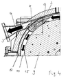
- Fig. 4 represents an enlarged section (approximately 1 ⁇ 4 circle) of the refiner, whereby the flows of the vapor / fiber mixture are also shown here.
- the steam / fiber mixture 13 formed in the refiner is located on the upper right Jardineck in the annular space 10 and rotated by the rotational movement of the rotor in the pressure housing with a certain speed (here counterclockwise).
- this steam / fiber mixture 13 is divided practically like a knife or scraper into a part 14 which exits the refiner 1 through the fiber outlet 3 and a part 15 which remains in the refiner pressure housing 2 (in the annular space 10).
- Fig. 5 shows a section in the region of the valve flap 11 It can be seen next to the refiner disc 9, the annular space 10, the deflection ring 12 and the tangential fiber outlet 3 and the valve flap 11 in a normal operating position.
- the valve flap 11 is rotatable about an axis 16, which is connected to the actuator 7, over an angular range 19.
- the entire steam / fiber mixture is diverted into the annular space 10, which is particularly advantageous during the starting process.
- the position “completely open” (18) of the valve flap 11 remains between the valve flap and the Refineremia 9 a small gap, wherein the valve flap 11 is set in extension of the fiber outlet 3 and thus the entire flow cross section of the same releases.
Landscapes
- Paper (AREA)
- Crushing And Grinding (AREA)
- Spinning Methods And Devices For Manufacturing Artificial Fibers (AREA)
- Disintegrating Or Milling (AREA)
Abstract
Description
- Die Erfindung betrifft einen Refiner mit mindestens einer rotierenden Refinerscheibe und einem Refinergehäuse, wobei das Refinergehäuse einen tangentialen Faserauslass und eine Einrichtung zur Kontrolle des Druckes und der Faserabströmung aufweist.
- Derartige Refiner sind z.B. aus der
WO 2006/112769 bekannt. Die mechanische Zerfaserung des Materials, meist Hackschnitzel, erfordert Energie, die durch die Refinersegmente auf den Refinerscheiben eingebracht wird. Diese Energie wird in Wärme umgesetzt, wodurch das im Material enthaltene Wasser verdampft und im Refinergehäuse einen Druck erzeugt. Der Großteil des Dampfes wird gemeinsam mit den erzeugten Fasern aus dem Refinergehäuse ausgetragen. Bei der Faserherstellung aus lignozellulosehaltigen Materialien, insbesondere für die Holzwerkstoffindustrie, z.B. für MDF Platten, werden Refiner eingesetzt, bei denen die ausströmende Dampfmenge aus dem Refiner mit Hilfe eines Blasventils kontrolliert wird. Mit dieser Dampfmenge wird gleichzeitig die erzeugte Faser in die nachfolgenden Prozesse über eine Rohrleitung (Blasleitung) transportiert. Das Blasventil ist direkt am Faserauslass des Refiners oder nach einem kurzen Rohrstück nach dem Refiner in der Blasleitung angebracht und wird so betrieben, dass die durch das Blasventil abströmende Dampfmenge so eingestellt ist, dass die über ein Frischdampfventil am Refinergehäuse zugeführte Frischdampfmenge so gering wie möglich gehalten werden kann. Durch das ständig abströmende Dampf/Fasergemisch ist eine entsprechende Frischdampfzufuhr erforderlich, um den Druck im Refinergehäuse konstant zu halten. Hier ist die minimale Dampfabfuhr und damit auch die anschließend erforderliche Frischdampfzufuhr durch den Faseranteil beschränkt, der gesamt abgeführt werden muss. Durch die Rotation der Refinerscheibe werden die erzeugten Fasern im Gehäuse herumgeschleudert, wodurch der Energieverbrauch erhöht wird. Auch besteht die Gefahr, dass die Fasern zusammenbacken und somit den Faserstrom bzw. die gesamte Abströmung des Dampf-Fasergemisches blockieren, was wiederum zu einem höheren Energieverbrauch führt. - Ziel der Erfindung ist es daher eine weitere Reduktion von Frischdampf und Energieeinsparung unabhängig von der abströmenden Fasermenge zu erreichen.
- Die Erfindung ist daher dadurch gekennzeichnet, dass im Gehäuse eine Ventilklappe vorgesehen ist. Durch diese Ventilklappe erfolgt eine Trennung des Dampf/Fasergemisches derart, dass nur Dampf abgeschieden wird, der am intensivsten mit Fasern durchmengt ist. Der weitestgehend faserfreie Dampfanteil verbleibt im Refiner, wodurch etwa diese Menge an Frischdampf gegenüber den bisherigen Systemen eingespart werden kann.
- Eine vorteilhafte Weiterbildung der Erfindung ist dadurch gekennzeichnet, dass die Ventilklappe zwischen einer Position offen und zu verstellbar ist. Damit kann auch die Verweilzeit der Fasern im Refiner und damit die Qualität der Zerfaserung kontrolliert werden. Weiters lässt sich die ausströmende Dampfmenge damit gut regeln.
- Eine günstige Ausgestaltung der Erfindung ist dadurch gekennzeichnet, dass die Ventilklappe mit einem außen am Refiner montierten Antrieb verbunden ist, wobei der Antrieb ein selbsthemmender Spindelantrieb sein kann. Mit dieser Ausführung lässt sich die Verstellung der Ventilklappe gut während des Betriebs durchführen.
- Die Erfindung wird nun anhand der Zeichnungen beispielhaft beschrieben, wobei
-
Fig. 1 die 3 D-Ansicht eines erfindungsgemäßen Refiners mit Antrieb, -
Fig. 2 eine Ansicht auf die Stirnseite eines erfindungsgemäßen Refiners, -
Fig. 3 einen Schnitt durch einen erfindungsgemäßen Refiner, -
Fig. 4 die Funktionsweise eines erfindungsgemäßen Refiners und -
Fig. 5 einen Ausschnitt eines erfindungsgemäßen Refiners im Bereich der Ventilklappe darstellt. -
Fig. 1 zeigt eine 3 D Ansicht eines erfindungsgemäßen Refiners 1 mit Refinergehäuse 2 und einem tangentialen Refinerauslass 3. Das Refinergehäuse 2 weist eine schwenkbare Refinertüre 4 und eine Frischdampfzufuhrleitung 5 auf. InFig. 1 ist weiters der Antrieb 6 (Motor) des Refiners 1 dargestellt. - In
Fig. 2 ist eine Frontalansicht auf einen erfindungsgemäßen Refiner 1 dargestellt. Neben dem tangential angeordneten Faserauslass 3 und der Refinertüre 4 kann man hier den Stellantrieb 7 für das Regelventil und den Antrieb 8, der hier als selbsthemmender Spindelantrieb ausgeführt ist, erkennen. Natürlich können auch andere Regelantriebe eingesetzt werden. -
Fig. 3 zeigt einen Schnitt durch ein erfindungsgemäßes Refinergehäuse 2 mit dem tangentialen Faserauslass 3. Um die Refinerscheibe 9 herum ist ein Ringraum 10 angeordnet, durch den das Dampf/Fasergemisch strömt. Im Bereich des Stutzens für den Faserauslass 3 befindet sich die Ventilklappe 11 (hier in der Position "ganz offen"). Die Ventilklappe befindet sich am Ende eines Umlenkrings 12. -
Fig. 4 stellt einen vergrößerten Ausschnitt (etwa ¼ Kreis) des Refiners dar, wobei hier auch die Strömungen des Dampf/Fasergemisches gezeigt werden. Das im Refiner gebildete Dampf/Fasergemisch 13 befindet sich am oberen rechten Bildeck im Ringraum 10 und rotiert durch die Drehbewegung des Rotors im Druckgehäuse mit einer gewissen Geschwindigkeit (hier gegen den Uhrzeigersinn). Durch die Ventilklappe 11 wird dieses Dampf/Fasergemisch 13 praktisch wie mit einem Messer oder Schaber in einen Teil 14, der durch den Faserauslass 3 aus dem Refiner 1 austritt und einen Teil 15, der im Refinerdruckgehäuse 2 (im Ringraum 10) verbleibt geteilt. Durch diese Trennung von Faser und Dampf ergibt sich die Möglichkeit einen nahezu faserfreien Dampf eher im Refiner zu belassen, wobei nur der Dampf abgeschieden wird, der am intensivsten mit Fasern durchmengt ist. Der Refiner wird somit zusätzlich zur Zerfaserung auch wie eine Faserzentrifuge zur Faser/Dampftrennung genutzt. Dadurch ergibt sich eine erhebliche Einsparung an Frischdampf, da nicht wie bisher der gesamte Dampf abgeführt wird. Durch die wesentlich höhere Faserkonzentration in der Blasleitung reduziert sich auch der Bedarf an Leim bei der nachgeschalteten Beleimung in der Blasleitung. -
Fig. 5 zeigt einen Ausschnitt im Bereich der Ventilklappe 11 Man erkennt neben der Refinerscheibe 9, dem Ringraum 10, dem Umlenkring 12 und dem tangentialen Faserauslass 3 auch die Ventilklappe 11 in einer üblichen Betriebsposition. Die Ventilklappe 11 ist um eine Achse 16, die mit dem Stellantrieb 7 verbunden ist, über einen Winkelbereich 19 drehbar. Bei der Position "ganz zu" (17) der Ventilklappe 11 wird das gesamte Dampf/Fasergemisch in den Ringraum 10 umgeleitet, was insbesondere beim Anfahrvorgang von Vorteil ist. Bei der Position "ganz offen" (18) der Ventilklappe 11 bleibt zwischen der Ventilklappe und der Refinerscheibe 9 ein kleiner Spalt, wobei die Ventilklappe 11 in Verlängerung des Faserauslasses 3 eingestellt ist und somit den gesamten Anströmquerschnitt desselben freigibt. Durch das Verschwenken der Ventilklappe 11 um die Achse 16 lässt sich immer ein optimaler Betriebspunkt für die Faserabgabe und Frischdampfbedarf einstellen.
Claims (4)
- Refiner mit mindestens einer rotierenden Refinerscheibe (9) und einem Refinergehäuse (2), wobei das Refinergehäuse (2) einen tangentialen Faserauslass (3) und eine Einrichtung zur Kontrolle des Druckes und der Faserabströmung aufweist, dadurch gekennzeichnet, dass im Gehäuse (2) eine Ventilklappe (11) vorgesehen ist.
- Refiner nach Anspruch 1, dadurch gekennzeichnet, dass die Ventilklappe (11) zwischen einer Position offen (18) und zu (17) verstellbar ist.
- Refiner nach Anspruch 2, dadurch gekennzeichnet, dass die Ventilklappe (11) mit einem außen am Refiner (1) montierten Antrieb (7,8) verbunden ist.
- Refiner nach Anspruch 3, dadurch gekennzeichnet, dass der Antrieb (7, 8) ein selbsthemmender Spindelantrieb ist.
Priority Applications (1)
| Application Number | Priority Date | Filing Date | Title |
|---|---|---|---|
| PL11009636T PL2468952T3 (pl) | 2010-12-23 | 2011-12-07 | Rafinator |
Applications Claiming Priority (1)
| Application Number | Priority Date | Filing Date | Title |
|---|---|---|---|
| ATA2127/2010A AT510594B1 (de) | 2010-12-23 | 2010-12-23 | Refiner |
Publications (2)
| Publication Number | Publication Date |
|---|---|
| EP2468952A1 true EP2468952A1 (de) | 2012-06-27 |
| EP2468952B1 EP2468952B1 (de) | 2013-06-19 |
Family
ID=45370375
Family Applications (1)
| Application Number | Title | Priority Date | Filing Date |
|---|---|---|---|
| EP11009636.9A Not-in-force EP2468952B1 (de) | 2010-12-23 | 2011-12-07 | Refiner |
Country Status (8)
| Country | Link |
|---|---|
| EP (1) | EP2468952B1 (de) |
| CN (1) | CN102535218B (de) |
| AT (1) | AT510594B1 (de) |
| BR (1) | BRPI1106976A2 (de) |
| CL (1) | CL2011003295A1 (de) |
| ES (1) | ES2428080T3 (de) |
| MY (1) | MY167736A (de) |
| PL (1) | PL2468952T3 (de) |
Families Citing this family (2)
| Publication number | Priority date | Publication date | Assignee | Title |
|---|---|---|---|---|
| CN110952359A (zh) * | 2019-12-16 | 2020-04-03 | 刘桥娣 | 一种提取植物皮肉纤维生产卫生巾的设备 |
| CN115229699B (zh) * | 2022-08-15 | 2023-07-18 | 陕西科技大学 | 一种等距直齿磨盘齿型设计方法、系统及计算机存储介质 |
Citations (3)
| Publication number | Priority date | Publication date | Assignee | Title |
|---|---|---|---|---|
| WO1983002788A1 (en) * | 1982-02-16 | 1983-08-18 | Klinga, Leif | Method and apparatus for producing fibre pulp from fibrous lignocellulose containing material |
| WO2006112769A1 (en) | 2005-04-18 | 2006-10-26 | Metso Panelboard Ab | Disc housing |
| DE102007022020A1 (de) * | 2007-05-08 | 2008-11-13 | Pallmann Maschinenfabrik Gmbh & Co Kg | Vorrichtung zum Aufbereiten von lignozellulosehaltigem Aufgabegut |
Family Cites Families (5)
| Publication number | Priority date | Publication date | Assignee | Title |
|---|---|---|---|---|
| GB763823A (en) * | 1955-01-31 | 1956-12-19 | Jackson And Church Company | Method for treating a fibrous material |
| SE435737B (sv) * | 1983-03-09 | 1984-10-15 | Sunds Defibrator | Sett och anordning for hel eller delvis atervinning av anga, som er tillford eller genererad vid en process for framstellning av fibermassa sett och anordning for hel eller delvis atervinning av anga, som er tillford eller genererad vid en process for framstellning av fibermassa |
| SE447737B (sv) * | 1983-11-30 | 1986-12-08 | Frotator Ab | Apparat for behandling av cellulosammassa med en konsistens ovanfor flytbarhetsgrensen med matningsbefremjande organ mellan bearbetande skivor |
| US5200038A (en) * | 1985-08-28 | 1993-04-06 | International Paper Company | Pulp refiner with fluidizing inlet |
| CN2078763U (zh) * | 1989-08-08 | 1991-06-12 | 张华� | 中浓低噪音反向双动盘磨机 |
-
2010
- 2010-12-23 AT ATA2127/2010A patent/AT510594B1/de not_active IP Right Cessation
-
2011
- 2011-12-07 EP EP11009636.9A patent/EP2468952B1/de not_active Not-in-force
- 2011-12-07 ES ES11009636T patent/ES2428080T3/es active Active
- 2011-12-07 PL PL11009636T patent/PL2468952T3/pl unknown
- 2011-12-21 MY MYPI2011006196A patent/MY167736A/en unknown
- 2011-12-23 BR BRPI1106976-7A patent/BRPI1106976A2/pt active Search and Examination
- 2011-12-23 CL CL2011003295A patent/CL2011003295A1/es unknown
- 2011-12-23 CN CN201110463121.6A patent/CN102535218B/zh not_active Expired - Fee Related
Patent Citations (3)
| Publication number | Priority date | Publication date | Assignee | Title |
|---|---|---|---|---|
| WO1983002788A1 (en) * | 1982-02-16 | 1983-08-18 | Klinga, Leif | Method and apparatus for producing fibre pulp from fibrous lignocellulose containing material |
| WO2006112769A1 (en) | 2005-04-18 | 2006-10-26 | Metso Panelboard Ab | Disc housing |
| DE102007022020A1 (de) * | 2007-05-08 | 2008-11-13 | Pallmann Maschinenfabrik Gmbh & Co Kg | Vorrichtung zum Aufbereiten von lignozellulosehaltigem Aufgabegut |
Also Published As
| Publication number | Publication date |
|---|---|
| BRPI1106976A2 (pt) | 2013-04-24 |
| EP2468952B1 (de) | 2013-06-19 |
| CN102535218A (zh) | 2012-07-04 |
| MY167736A (en) | 2018-09-24 |
| ES2428080T3 (es) | 2013-11-06 |
| AT510594A4 (de) | 2012-05-15 |
| CN102535218B (zh) | 2016-03-09 |
| CL2011003295A1 (es) | 2012-04-27 |
| AT510594B1 (de) | 2012-05-15 |
| PL2468952T3 (pl) | 2013-11-29 |
| RU2011152272A (ru) | 2013-06-27 |
Similar Documents
| Publication | Publication Date | Title |
|---|---|---|
| EP2213431B1 (de) | Verfahren und Anlage zur Herstellung von Faser-, MDF, HDF, Holzwerkstoff- oder Kunststoffplatten aus Fasern oder faserähnlichem Material | |
| DE60037695T2 (de) | Refinerplatte mit Düseneinlass | |
| DE60023658T2 (de) | Scheibenmühle mit tangentialem austritt | |
| EP1017550B1 (de) | Verfahren zum beleimen von fasern | |
| DE102008059877A1 (de) | Verfahren und Vorrichtung zur Beleimung von Spänen, Fasern oder faserähnlichem Material im Zuge der Herstellung von Werkstoffplatten | |
| DE2905419A1 (de) | Verfahren und einrichtung zum steuern der einwirkung der fliehkraft auf das mahlgut in einem mahlapparat fuer zellstoffherstellung | |
| WO2015055466A1 (de) | Vorrichtung und verfahren zum reinigen von kunststoff im zuge von kunststoffrecycling | |
| AT390455B (de) | Vorrichtung zum zerkleinern von fasermaterial | |
| DE3135509A1 (de) | Verfahren und vorrichtung zum vermahlen von faserigem ausgangsgut in mahlapparaten der doppelumlaufscheiben-bauart | |
| EP3027806B1 (de) | Anlage und verfahren zum verarbeiten von faserstoffen | |
| AT510594B1 (de) | Refiner | |
| DE69618255T2 (de) | Paarweise zusammenwirkende zerkleinerungselementen für eine scheibenfeinmühle | |
| AT405537B (de) | Vorrichtung zur entwässerung und zerfaserung von lignozellulosem material | |
| DE2323442A1 (de) | Verfahren und vorrichtung zum raffinieren eines mahlmaterials | |
| DE102015101530A1 (de) | Zerkleinerungsvorrichtung zur Rückgewinnung von Sekundärrohstoffen aus entsorgtem Material sowie Verfahren zu deren Steuerung | |
| AT527210B1 (de) | Anlage und verfahren zur herstellung einer faserplatte | |
| DE69209849T2 (de) | Vorrichtung zum teilen einer fasermaterialströmung in mindestens zwei gleiche strömungen | |
| DE102013206275A1 (de) | Verfahren und Vorrichtung zum Zerkleinern | |
| AT514329B1 (de) | Anlage und Verfahren zum Verarbeiten von Faserstoffen | |
| DE102007022020A1 (de) | Vorrichtung zum Aufbereiten von lignozellulosehaltigem Aufgabegut | |
| DE946278C (de) | Vorrichtung zur ununterbrochenen Defibration von Faserstoffen mittels hochgespannten Dampfes | |
| DE102015107321A1 (de) | Vorrichtung und Verfahren zum Beleimen von Fasern oder faserähnlichem Material | |
| DE657808C (de) | Vorrichtung zur Herstellung von Faser-, insbesondere Papierstoff | |
| EP1871949A1 (de) | Scheibengehäuse | |
| DE2334196C3 (de) | Kegelförmige Schleuder-Prallmühle |
Legal Events
| Date | Code | Title | Description |
|---|---|---|---|
| AK | Designated contracting states |
Kind code of ref document: A1 Designated state(s): AL AT BE BG CH CY CZ DE DK EE ES FI FR GB GR HR HU IE IS IT LI LT LU LV MC MK MT NL NO PL PT RO RS SE SI SK SM TR |
|
| AX | Request for extension of the european patent |
Extension state: BA ME |
|
| PUAI | Public reference made under article 153(3) epc to a published international application that has entered the european phase |
Free format text: ORIGINAL CODE: 0009012 |
|
| 17P | Request for examination filed |
Effective date: 20121217 |
|
| GRAP | Despatch of communication of intention to grant a patent |
Free format text: ORIGINAL CODE: EPIDOSNIGR1 |
|
| RIC1 | Information provided on ipc code assigned before grant |
Ipc: D21D 1/30 20060101AFI20130110BHEP |
|
| GRAS | Grant fee paid |
Free format text: ORIGINAL CODE: EPIDOSNIGR3 |
|
| GRAA | (expected) grant |
Free format text: ORIGINAL CODE: 0009210 |
|
| AK | Designated contracting states |
Kind code of ref document: B1 Designated state(s): AL AT BE BG CH CY CZ DE DK EE ES FI FR GB GR HR HU IE IS IT LI LT LU LV MC MK MT NL NO PL PT RO RS SE SI SK SM TR |
|
| REG | Reference to a national code |
Ref country code: GB Ref legal event code: FG4D Free format text: NOT ENGLISH |
|
| REG | Reference to a national code |
Ref country code: CH Ref legal event code: EP |
|
| REG | Reference to a national code |
Ref country code: AT Ref legal event code: REF Ref document number: 617731 Country of ref document: AT Kind code of ref document: T Effective date: 20130715 |
|
| REG | Reference to a national code |
Ref country code: IE Ref legal event code: FG4D Free format text: LANGUAGE OF EP DOCUMENT: GERMAN |
|
| REG | Reference to a national code |
Ref country code: DE Ref legal event code: R096 Ref document number: 502011000911 Country of ref document: DE Effective date: 20130814 |
|
| PG25 | Lapsed in a contracting state [announced via postgrant information from national office to epo] |
Ref country code: NO Free format text: LAPSE BECAUSE OF FAILURE TO SUBMIT A TRANSLATION OF THE DESCRIPTION OR TO PAY THE FEE WITHIN THE PRESCRIBED TIME-LIMIT Effective date: 20130919 Ref country code: LT Free format text: LAPSE BECAUSE OF FAILURE TO SUBMIT A TRANSLATION OF THE DESCRIPTION OR TO PAY THE FEE WITHIN THE PRESCRIBED TIME-LIMIT Effective date: 20130619 Ref country code: SE Free format text: LAPSE BECAUSE OF FAILURE TO SUBMIT A TRANSLATION OF THE DESCRIPTION OR TO PAY THE FEE WITHIN THE PRESCRIBED TIME-LIMIT Effective date: 20130619 Ref country code: SI Free format text: LAPSE BECAUSE OF FAILURE TO SUBMIT A TRANSLATION OF THE DESCRIPTION OR TO PAY THE FEE WITHIN THE PRESCRIBED TIME-LIMIT Effective date: 20130619 Ref country code: GR Free format text: LAPSE BECAUSE OF FAILURE TO SUBMIT A TRANSLATION OF THE DESCRIPTION OR TO PAY THE FEE WITHIN THE PRESCRIBED TIME-LIMIT Effective date: 20130920 Ref country code: FI Free format text: LAPSE BECAUSE OF FAILURE TO SUBMIT A TRANSLATION OF THE DESCRIPTION OR TO PAY THE FEE WITHIN THE PRESCRIBED TIME-LIMIT Effective date: 20130619 |
|
| REG | Reference to a national code |
Ref country code: ES Ref legal event code: FG2A Ref document number: 2428080 Country of ref document: ES Kind code of ref document: T3 Effective date: 20131106 |
|
| REG | Reference to a national code |
Ref country code: LT Ref legal event code: MG4D |
|
| PG25 | Lapsed in a contracting state [announced via postgrant information from national office to epo] |
Ref country code: RS Free format text: LAPSE BECAUSE OF FAILURE TO SUBMIT A TRANSLATION OF THE DESCRIPTION OR TO PAY THE FEE WITHIN THE PRESCRIBED TIME-LIMIT Effective date: 20130619 Ref country code: BG Free format text: LAPSE BECAUSE OF FAILURE TO SUBMIT A TRANSLATION OF THE DESCRIPTION OR TO PAY THE FEE WITHIN THE PRESCRIBED TIME-LIMIT Effective date: 20130919 Ref country code: HR Free format text: LAPSE BECAUSE OF FAILURE TO SUBMIT A TRANSLATION OF THE DESCRIPTION OR TO PAY THE FEE WITHIN THE PRESCRIBED TIME-LIMIT Effective date: 20130619 |
|
| REG | Reference to a national code |
Ref country code: PL Ref legal event code: T3 |
|
| REG | Reference to a national code |
Ref country code: NL Ref legal event code: VDEP Effective date: 20130619 |
|
| PG25 | Lapsed in a contracting state [announced via postgrant information from national office to epo] |
Ref country code: LV Free format text: LAPSE BECAUSE OF FAILURE TO SUBMIT A TRANSLATION OF THE DESCRIPTION OR TO PAY THE FEE WITHIN THE PRESCRIBED TIME-LIMIT Effective date: 20130619 |
|
| PG25 | Lapsed in a contracting state [announced via postgrant information from national office to epo] |
Ref country code: EE Free format text: LAPSE BECAUSE OF FAILURE TO SUBMIT A TRANSLATION OF THE DESCRIPTION OR TO PAY THE FEE WITHIN THE PRESCRIBED TIME-LIMIT Effective date: 20130619 Ref country code: CZ Free format text: LAPSE BECAUSE OF FAILURE TO SUBMIT A TRANSLATION OF THE DESCRIPTION OR TO PAY THE FEE WITHIN THE PRESCRIBED TIME-LIMIT Effective date: 20130619 Ref country code: SK Free format text: LAPSE BECAUSE OF FAILURE TO SUBMIT A TRANSLATION OF THE DESCRIPTION OR TO PAY THE FEE WITHIN THE PRESCRIBED TIME-LIMIT Effective date: 20130619 Ref country code: IS Free format text: LAPSE BECAUSE OF FAILURE TO SUBMIT A TRANSLATION OF THE DESCRIPTION OR TO PAY THE FEE WITHIN THE PRESCRIBED TIME-LIMIT Effective date: 20131019 Ref country code: PT Free format text: LAPSE BECAUSE OF FAILURE TO SUBMIT A TRANSLATION OF THE DESCRIPTION OR TO PAY THE FEE WITHIN THE PRESCRIBED TIME-LIMIT Effective date: 20131021 Ref country code: CY Free format text: LAPSE BECAUSE OF FAILURE TO SUBMIT A TRANSLATION OF THE DESCRIPTION OR TO PAY THE FEE WITHIN THE PRESCRIBED TIME-LIMIT Effective date: 20130828 |
|
| PG25 | Lapsed in a contracting state [announced via postgrant information from national office to epo] |
Ref country code: RO Free format text: LAPSE BECAUSE OF FAILURE TO SUBMIT A TRANSLATION OF THE DESCRIPTION OR TO PAY THE FEE WITHIN THE PRESCRIBED TIME-LIMIT Effective date: 20130619 Ref country code: NL Free format text: LAPSE BECAUSE OF FAILURE TO SUBMIT A TRANSLATION OF THE DESCRIPTION OR TO PAY THE FEE WITHIN THE PRESCRIBED TIME-LIMIT Effective date: 20130619 |
|
| PG25 | Lapsed in a contracting state [announced via postgrant information from national office to epo] |
Ref country code: CY Free format text: LAPSE BECAUSE OF FAILURE TO SUBMIT A TRANSLATION OF THE DESCRIPTION OR TO PAY THE FEE WITHIN THE PRESCRIBED TIME-LIMIT Effective date: 20130619 |
|
| PLBE | No opposition filed within time limit |
Free format text: ORIGINAL CODE: 0009261 |
|
| STAA | Information on the status of an ep patent application or granted ep patent |
Free format text: STATUS: NO OPPOSITION FILED WITHIN TIME LIMIT |
|
| PG25 | Lapsed in a contracting state [announced via postgrant information from national office to epo] |
Ref country code: DK Free format text: LAPSE BECAUSE OF FAILURE TO SUBMIT A TRANSLATION OF THE DESCRIPTION OR TO PAY THE FEE WITHIN THE PRESCRIBED TIME-LIMIT Effective date: 20130619 |
|
| 26N | No opposition filed |
Effective date: 20140320 |
|
| PG25 | Lapsed in a contracting state [announced via postgrant information from national office to epo] |
Ref country code: IT Free format text: LAPSE BECAUSE OF FAILURE TO SUBMIT A TRANSLATION OF THE DESCRIPTION OR TO PAY THE FEE WITHIN THE PRESCRIBED TIME-LIMIT Effective date: 20130619 |
|
| REG | Reference to a national code |
Ref country code: DE Ref legal event code: R097 Ref document number: 502011000911 Country of ref document: DE Effective date: 20140320 |
|
| BERE | Be: lapsed |
Owner name: ANDRITZ AG Effective date: 20131231 |
|
| PG25 | Lapsed in a contracting state [announced via postgrant information from national office to epo] |
Ref country code: LU Free format text: LAPSE BECAUSE OF FAILURE TO SUBMIT A TRANSLATION OF THE DESCRIPTION OR TO PAY THE FEE WITHIN THE PRESCRIBED TIME-LIMIT Effective date: 20131207 |
|
| REG | Reference to a national code |
Ref country code: IE Ref legal event code: MM4A |
|
| REG | Reference to a national code |
Ref country code: FR Ref legal event code: ST Effective date: 20140829 |
|
| PG25 | Lapsed in a contracting state [announced via postgrant information from national office to epo] |
Ref country code: IE Free format text: LAPSE BECAUSE OF NON-PAYMENT OF DUE FEES Effective date: 20131207 Ref country code: BE Free format text: LAPSE BECAUSE OF NON-PAYMENT OF DUE FEES Effective date: 20131231 |
|
| PG25 | Lapsed in a contracting state [announced via postgrant information from national office to epo] |
Ref country code: FR Free format text: LAPSE BECAUSE OF NON-PAYMENT OF DUE FEES Effective date: 20131231 |
|
| PG25 | Lapsed in a contracting state [announced via postgrant information from national office to epo] |
Ref country code: MC Free format text: LAPSE BECAUSE OF FAILURE TO SUBMIT A TRANSLATION OF THE DESCRIPTION OR TO PAY THE FEE WITHIN THE PRESCRIBED TIME-LIMIT Effective date: 20130619 |
|
| PG25 | Lapsed in a contracting state [announced via postgrant information from national office to epo] |
Ref country code: SM Free format text: LAPSE BECAUSE OF FAILURE TO SUBMIT A TRANSLATION OF THE DESCRIPTION OR TO PAY THE FEE WITHIN THE PRESCRIBED TIME-LIMIT Effective date: 20130619 |
|
| PG25 | Lapsed in a contracting state [announced via postgrant information from national office to epo] |
Ref country code: MK Free format text: LAPSE BECAUSE OF FAILURE TO SUBMIT A TRANSLATION OF THE DESCRIPTION OR TO PAY THE FEE WITHIN THE PRESCRIBED TIME-LIMIT Effective date: 20130619 Ref country code: HU Free format text: LAPSE BECAUSE OF FAILURE TO SUBMIT A TRANSLATION OF THE DESCRIPTION OR TO PAY THE FEE WITHIN THE PRESCRIBED TIME-LIMIT; INVALID AB INITIO Effective date: 20111207 |
|
| REG | Reference to a national code |
Ref country code: CH Ref legal event code: PL |
|
| PG25 | Lapsed in a contracting state [announced via postgrant information from national office to epo] |
Ref country code: MT Free format text: LAPSE BECAUSE OF FAILURE TO SUBMIT A TRANSLATION OF THE DESCRIPTION OR TO PAY THE FEE WITHIN THE PRESCRIBED TIME-LIMIT Effective date: 20130619 |
|
| PG25 | Lapsed in a contracting state [announced via postgrant information from national office to epo] |
Ref country code: CH Free format text: LAPSE BECAUSE OF NON-PAYMENT OF DUE FEES Effective date: 20141231 Ref country code: LI Free format text: LAPSE BECAUSE OF NON-PAYMENT OF DUE FEES Effective date: 20141231 |
|
| GBPC | Gb: european patent ceased through non-payment of renewal fee |
Effective date: 20151207 |
|
| PG25 | Lapsed in a contracting state [announced via postgrant information from national office to epo] |
Ref country code: GB Free format text: LAPSE BECAUSE OF NON-PAYMENT OF DUE FEES Effective date: 20151207 |
|
| PGFP | Annual fee paid to national office [announced via postgrant information from national office to epo] |
Ref country code: TR Payment date: 20171207 Year of fee payment: 7 |
|
| REG | Reference to a national code |
Ref country code: AT Ref legal event code: MM01 Ref document number: 617731 Country of ref document: AT Kind code of ref document: T Effective date: 20161207 |
|
| PG25 | Lapsed in a contracting state [announced via postgrant information from national office to epo] |
Ref country code: AT Free format text: LAPSE BECAUSE OF NON-PAYMENT OF DUE FEES Effective date: 20161207 |
|
| PG25 | Lapsed in a contracting state [announced via postgrant information from national office to epo] |
Ref country code: AL Free format text: LAPSE BECAUSE OF FAILURE TO SUBMIT A TRANSLATION OF THE DESCRIPTION OR TO PAY THE FEE WITHIN THE PRESCRIBED TIME-LIMIT Effective date: 20130619 |
|
| PGFP | Annual fee paid to national office [announced via postgrant information from national office to epo] |
Ref country code: PL Payment date: 20181123 Year of fee payment: 8 Ref country code: DE Payment date: 20181210 Year of fee payment: 8 |
|
| PGFP | Annual fee paid to national office [announced via postgrant information from national office to epo] |
Ref country code: ES Payment date: 20190123 Year of fee payment: 8 |
|
| REG | Reference to a national code |
Ref country code: DE Ref legal event code: R119 Ref document number: 502011000911 Country of ref document: DE |
|
| PG25 | Lapsed in a contracting state [announced via postgrant information from national office to epo] |
Ref country code: DE Free format text: LAPSE BECAUSE OF NON-PAYMENT OF DUE FEES Effective date: 20200701 |
|
| REG | Reference to a national code |
Ref country code: ES Ref legal event code: FD2A Effective date: 20210601 |
|
| PG25 | Lapsed in a contracting state [announced via postgrant information from national office to epo] |
Ref country code: ES Free format text: LAPSE BECAUSE OF NON-PAYMENT OF DUE FEES Effective date: 20191208 |
|
| PG25 | Lapsed in a contracting state [announced via postgrant information from national office to epo] |
Ref country code: PL Free format text: LAPSE BECAUSE OF NON-PAYMENT OF DUE FEES Effective date: 20191207 |
|
| PG25 | Lapsed in a contracting state [announced via postgrant information from national office to epo] |
Ref country code: TR Free format text: LAPSE BECAUSE OF NON-PAYMENT OF DUE FEES Effective date: 20191207 |