EP2468146A1 - Kühlthekeneinsatz - Google Patents
Kühlthekeneinsatz Download PDFInfo
- Publication number
- EP2468146A1 EP2468146A1 EP11009689A EP11009689A EP2468146A1 EP 2468146 A1 EP2468146 A1 EP 2468146A1 EP 11009689 A EP11009689 A EP 11009689A EP 11009689 A EP11009689 A EP 11009689A EP 2468146 A1 EP2468146 A1 EP 2468146A1
- Authority
- EP
- European Patent Office
- Prior art keywords
- handle
- support surface
- goods support
- insert according
- counter insert
- Prior art date
- Legal status (The legal status is an assumption and is not a legal conclusion. Google has not performed a legal analysis and makes no representation as to the accuracy of the status listed.)
- Granted
Links
- 238000001816 cooling Methods 0.000 claims description 45
- 238000007789 sealing Methods 0.000 claims description 4
- 238000003825 pressing Methods 0.000 claims description 2
- 239000004744 fabric Substances 0.000 claims 1
- 230000037431 insertion Effects 0.000 abstract 1
- 238000003780 insertion Methods 0.000 abstract 1
- 238000004140 cleaning Methods 0.000 description 6
- 239000002184 metal Substances 0.000 description 2
- 239000004033 plastic Substances 0.000 description 2
- 229920003023 plastic Polymers 0.000 description 2
- 229920005830 Polyurethane Foam Polymers 0.000 description 1
- 229910000639 Spring steel Inorganic materials 0.000 description 1
- 229920006328 Styrofoam Polymers 0.000 description 1
- 230000006835 compression Effects 0.000 description 1
- 238000007906 compression Methods 0.000 description 1
- 230000001419 dependent effect Effects 0.000 description 1
- 230000000694 effects Effects 0.000 description 1
- 230000001747 exhibiting effect Effects 0.000 description 1
- 239000011810 insulating material Substances 0.000 description 1
- 238000004519 manufacturing process Methods 0.000 description 1
- 238000000034 method Methods 0.000 description 1
- 239000011496 polyurethane foam Substances 0.000 description 1
- 239000008261 styrofoam Substances 0.000 description 1
Images


Classifications
-
- A—HUMAN NECESSITIES
- A47—FURNITURE; DOMESTIC ARTICLES OR APPLIANCES; COFFEE MILLS; SPICE MILLS; SUCTION CLEANERS IN GENERAL
- A47F—SPECIAL FURNITURE, FITTINGS, OR ACCESSORIES FOR SHOPS, STOREHOUSES, BARS, RESTAURANTS OR THE LIKE; PAYING COUNTERS
- A47F3/00—Show cases or show cabinets
- A47F3/04—Show cases or show cabinets air-conditioned, refrigerated
- A47F3/0482—Details common to both closed and open types
- A47F3/0486—Details common to both closed and open types for charging, displaying or discharging the articles
-
- A—HUMAN NECESSITIES
- A47—FURNITURE; DOMESTIC ARTICLES OR APPLIANCES; COFFEE MILLS; SPICE MILLS; SUCTION CLEANERS IN GENERAL
- A47F—SPECIAL FURNITURE, FITTINGS, OR ACCESSORIES FOR SHOPS, STOREHOUSES, BARS, RESTAURANTS OR THE LIKE; PAYING COUNTERS
- A47F3/00—Show cases or show cabinets
- A47F3/06—Show cases or show cabinets with movable or removable shelves or receptacles
Definitions
- the preceding invention relates to a counter insert according to the preamble of claim 1.
- a generic counter insert in particular a refrigerated counter insert, has a tilt-adjustable goods support surface and a handle for lifting at least the goods support surface in an inclined position.
- Another generic counter insert is in DE 100 64 633 A1 described.
- a projection is provided on a trough of the counter insert and on the goods support surface a flexible support is provided, which is supported on the projection.
- an object of the invention can be considered to provide a counter insert whose Painauflage Materials is movable and sustainable in a particularly simple operation in different inclination positions.
- the handle for holding the goods support surface in the inclined position, the handle is movable into a support position in which the handle is supported on a stationary part, and in that a spring device is in operative connection with the handle, which moves the handle in the inclined position automatically in the support position.
- the handle is designed to be movable relative to the goods support surface.
- the spring device itself is not supported on the fixed part. Rather, according to the invention, the spring device is completely gripped in an operating position. That is, the spring means press against an inner wall of the handle, not against a fixed part, in particular not a fixed part of a trough of the counter insert.
- a fixed part is to be understood as meaning any component of the counter insert which is not moved during a movement of the tilt-adjustable goods support surface, but is fixed.
- a cooling device is provided, which is arranged under the goods support surface and connected thereto, that the cooling device has an open side adjacent to the handle, that the handle is hollow for receiving cooled Air exiting the open side of the cooling device, and that the handle has an outflow opening for guiding cooled air from the cooling device to the goods bearing surface.
- the cooling device may have a suction opening for sucking air to be cooled, which is cooled in the cooling device and then discharged through the open side.
- the handle When an inflow port of the handle directly adjoins the open side of the radiator, the cooled air exiting through the open side flows largely or even completely into the grip.
- the handle thus forms part of a flow channel below the goods support surface, is passed through the cooled air to goods on the goods support surface.
- An advantageous alternative of the counter insert according to the invention is characterized in that, when the goods support surface is inclined, the handle can be swiveled out above a support position into an opening position in which the open side of the cooling device is made accessible.
- the cooling device is largely accessible through the open side, so that, for example, cleaning work can be carried out. In this position, the bottom of the cooling device is accessible. In operating positions, however, this underside is shielded by a trough of the counter insert, in which the goods support surface is receivable.
- operating positions are to be understood positions of the goods support surface and the handle, in which an operation is possible, so exhibiting and cooling of goods on the goods support surface.
- the operating positions to include the support positions in which the handle for supporting the goods support surface is supported at an angle to a fixed part of the counter insert.
- the goods support surface in a higher position ie a larger- ⁇ eren Tilt angle, as is the case with operating positions, are moved.
- the access to the cooling device is facilitated by the handle is folded relative to the goods support surface, in particular by an angle greater than 90 °, preferably greater than 120 °.
- the entire component that has this gripping area should be understood as a handle.
- the component is preferably formed in one piece.
- a further embodiment of the counter insert according to the invention is characterized in that a connecting element is provided substantially perpendicular to the goods support surface and is connected to the goods support surface, and that the handle on the connecting element, in particular at a remote from the goods support surface end of the connecting element is pivotally articulated.
- the handle can be swung around the junction in a support position and / or in the open position.
- the spring device is fixedly but detachably connected to the goods support surface, in particular via the connecting element connected to the goods support surface.
- the spring device may for example be a rod shape or plate-like and be formed from or with a flexible metal, in particular a spring steel, or plastic.
- the spring device is fastened to the connecting element such that, in an operating position, it presses obliquely against an inner side of the handle, that is to say at an angle not equal to 90 °, preferably less than 70 °.
- the spring device may also have a spiral spring, which may in particular be perpendicular to the inside of the handle, or be designed with a compression spring, gas spring or similar spring.
- a, in particular temperature-insulated, tub is provided, in which the goods support surface is receivable, and that the trough has the fixed part to which the handle can be supported.
- the fixed part may be formed by an upper surface or edge of the tub.
- no projection on the inner rear wall is necessary, on which the handle would be supported. This reduces the production costs and facilitates cleaning work.
- the uppermost surface of the tub can be understood, which is in the basic position of the goods support surface in about its height and enclosing it in the horizontal direction.
- the tub can be made of an insulating material, for example Styrofoam, or polyurethane foam, or other foamed plastic, and be provided with a lining, in particular a metal panel, inside and outside.
- an insulating material for example Styrofoam, or polyurethane foam, or other foamed plastic
- the goods support surface is movable into a plurality of inclination positions, in which the goods support surface can each be supported on the fixed part by means of the handle.
- the handle may have a stair-shaped support region for supporting on the fixed part, wherein the goods support surface in the plurality of inclination positions can be supported by the stair-shaped support region.
- the handle In the different tilt positions, the handle is in different support positions in which he pressed by the spring means different far, so swung out is.
- the inner rear wall of the tub may have the form of steps, wherein each step represents a fixed part on which the handle can be supported.
- the handle has a trough-like lower inflow opening for cooled air and a trough-like, in particular directed, upper outflow opening for directing cooled air onto the goods support surface.
- the discharge opening may air guide elements, such. As honeycomb grid or the like, include.
- the lower region of the handle has a rounding, in particular for largely airtight sealing of the flow channel in the basic position and in each support position.
- the handle In the various support positions, the handle is swung out differently far. Therefore, it can be ensured by a rounding that regardless of whether the handle is pivoted to a support position, an airtight seal is present. That is, the entire air flowing out of the cooling device comes into the grip.
- a basic position can be understood a position of the goods support surface in which the goods support surface is not held by the handle.
- a rounding of the handle is designed so that a largely continuous tilt adjustment of the goods support surface is made possible, with the down-pressing weight of the goods support surface and provided there facilities, in particular the cooling device, the handle in one Supporting position holds. Due to the rounding, the grip depends on how far it is swung out, at different heights on the fixed part. In this case, the weight of the goods support surface prevents the spring device unintentionally swing the handle further and thus increase a tilt angle.
- a slot is provided on a lower side of the handle and a tab connected to the goods support surface is provided, which engages in the slot to guide a movement of the handle in support positions.
- the slot can also be designed as a groove or groove. It is also possible to form the tab as a nose.
- the handle can have a passage for the spring device for pivoting into an open position.
- the passage is located on one of the goods bearing surface facing side of the handle.
- sealing lips, a sealing comb or another flexible lining may be present at the passage.
- a support region of the handle which can be supported on the fixed part, is shaped in such a way that, in a supporting position, the support region of the handle is supported flat on the fixed part, ie not just with one edge.
- a bearing surface of the handle is increased and thus reduces the risk that scratches or damage to the fixed part and / or the handle.
- FIGS. 1 and 2 show an embodiment of a counter insert according to the invention in operating positions.
- the counter insert 100 has a trough 30, a goods support surface 10 and a handle 20 for lifting at least the goods support surface 10 in a tilt position.
- a cooling device 60 is present below the goods support surface 10. This can be firmly connected to the goods support surface 10. In operating positions, the cooling device 60 is thus largely received in the tub 30.
- the cooling device 60 has an intake opening 62, through which air to be cooled, in particular from an area above the goods support surface 10, can be sucked into the cooling device 60.
- the cooling device 60 may have an intake fan 65. The sucked air then flows through an evaporator 66 of the cooling device 60 and is cooled. Through an open side 61 of the cooling device 60, the cooled air finally leaves the cooling device 60.
- the cooling device 60 thus forms part of a flow channel in which all of the air drawn in through the suction opening 62 is discharged on the open side 61.
- a lower boundary of the cooling device 60 is expedient.
- the lower boundary of the cooling device 60 is formed approximately through the bottom of the tub 30. That is, the bottom of the tub 30 is shaped so that air to be cooled is discharged through the open side 61 of the cooler 60.
- counter insert 100 is the goods support 10 in an inclined, that is raised, position.
- the cooling device 60 is thereby also raised and thereby spaced from the bottom of the trough 30.
- a drag plate 63 is present. This is pivotally hinged to the cooling device 60. When lifting the goods support surface 10 and thus the cooling device 60, the drag plate 63 folds down due to its own weight and thus secures a guide of the air to be cooled.
- the handle 20 If the handle 20 is raised by a user, the handle 20 is automatically swung out and thereby brought into the supporting position.
- a spring device 50 is present, which is connected to the goods support surface 10.
- the spring device 50 is attached to a connecting element 12 which is connected to the goods support surface 10.
- the handle 20 is also attached to the connecting element 12 and is pivotable to this. In the in the FIGS. 1 and 2 shown operating positions, the spring device 50 is largely surrounded by the handle 20.
- the spring device 50 presses the handle 20 against an inner rear wall 31 of the trough 30.
- a rear side 26 of the handle 20 is shaped such that in the basic position in which a lower part of the handle 20 is received in the interior of the trough 30 is, this is at least in a partial area parallel to the inner rear wall 31 of the tub 30.
- the rear side 26 of the handle 20 lies flat against the inner rear wall 31.
- the inflow opening 23 in the handle 20 remains free and faces the cooling device.
- the handle 20 serves not only for lifting the goods support surface 10 and for supporting the goods support surface 10 in an inclined position, but also for guiding cooled air to the goods support surface 10.
- the handle 20 is hollow and has an inflow opening 23 and an outflow opening 24 , Both in the basic position and in the support position, the handle 20 is in a position in which the inflow opening 23 is directly adjacent to the open side 61 of the cooling device 60. As a result, the entire air cooled by the cooling device 60 reaches the handle 20 and subsequently out of the outflow opening 24 onto the goods support surface 10.
- a bottom 21 of the handle 20 may be airtight with a part of the cooling device Complete 60.
- the underside 21 of the handle 20 may be rounded.
- the goods support surface 10 on the in Fig. 2 lift out the tilt position shown. This case is in Fig. 3 shown.
- the interior of the tub 30 and the bottom of the cooling device 60 are accessible.
- the open side 61 is accessible to operating personnel, so that the cooling device 60, for example, can be cleaned or maintained from the inside more easily.
- the handle 20 is kept independent in the open position.
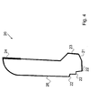
- Fig. 4 shows a handle 20 of another embodiment of a counter insert according to the invention.
- the handle 20 shown here is designed to support the goods support surface 10 in different inclination positions, that is, inclination angles.
- the handle 20 in a lower region, which can be supported on the fixed part 35, a stepped support portion 22.
- a stepped support portion 22 is at least two steps 22, in the illustrated case three steps 22, available.
- a different angle of inclination can be adjusted.
- the counter insert according to the invention it is possible to make an adjustment of the inclination angle of the goods support surface solely by lifting the handle.
- the counter insert according to the invention in the raised, open position allows a good cleaning possibility of the tub and underside of the cooling device.
- the goods support 10 can be folded up by unlocking without entrainment of the cooling device 60, so that a particularly good Access for cleaning purposes is enabled.
- the handle height can be variable - depending on the height of the goods to be cooled - executed.
Landscapes
- Physics & Mathematics (AREA)
- Thermal Sciences (AREA)
- Devices That Are Associated With Refrigeration Equipment (AREA)
Abstract
Description
- Die vorgehende Erfindung bezieht sich auf einen Thekeneinsatz nach dem Oberbegriff des Anspruchs 1.
- Ein gattungsgemäßer Thekeneinsatz, insbesondere ein Kühlthekeneinsatz, weist eine neigungsverstellbare Warenauflagefläche und einen Griff zum Anheben mindestens der Warenauflagefläche in eine geneigte Stellung auf.
- Ein derartiger Thekeneinsatz ist aus
DE 299 10 539 U1 bekannt. Nachteilig ist hierbei, dass zum Befestigen der Warenauflagefläche in einer oberen, geneigten Stellung eine scharnierartig angebrachte Klappe erforderlich ist, die manuell herausgeklappt werden muss. - Ein weiterer gattungsgemäßer Thekeneinsatz ist in
DE 100 64 633 A1 beschrieben. Zum Halten der Warenauflagefläche in der geneigten Stellung ist dabei an einer Wanne des Thekeneinsatzes ein Vorsprung vorgesehen und an der Warenauflagefläche ist eine flexible Abstützung vorhanden, die auf den Vorsprung abgestützt wird. - Um die Warenauflagefläche von einer geneigten Stellung in eine untere Stellung zu bewegen, ist es hier erforderlich, mit einer Hand die flexible Abstützung aus der Stützposition zu lösen, während die andere Hand den Griff hält. Dieser Vorgang ist relativ kompliziert und wird zudem dadurch erschwert, dass die flexible Abstützung nur schwer zugänglich ist.
- Ein weiterer gattungsgemäßer Thekeneinsatz ist aus
DE 94 09 985 bekannt. - Bei den herkömmlichen Thekeneinsätzen ist nachteilig, dass ein Verstellen der Neigung der Warenauflagefläche einen relativ hohen Aufwand erfordert. Außerdem geht abhängig von der Neigungsstellung der Warenauflagefläche Kühlluft verloren, das heißt, die Kühlluft wird nur teilweise auf die Warenauflagefläche geleitet.
- Als eine Aufgabe der Erfindung kann angesehen werden, einen Thekeneinsatz bereitzustellen, dessen Warenauflagefläche bei besonders einfacher Bedienung in verschiedenen Neigungspositionen bewegbar und stützbar ist.
- Diese Aufgabe wird durch den Thekeneinsatz mit den Merkmalen des Anspruchs 1 gelöst.
- Vorteilhafte Ausgestaltungen des erfindungsgemäßen Thekeneinsatzes sind Gegenstand der abhängigen Ansprüche und werden außerdem in der folgenden Beschreibung, insbesondere in Zusammenhang mit den Figuren, beschrieben.
- Bei dem Thekeneinsatz der oben genannten Art ist erfindungsgemäß vorgesehen, dass zum Halten der Warenauflagefläche in der geneigten Stellung der Griff in eine Stützposition bewegbar ist, in welcher der Griff auf einem feststehenden Teil abgestützt ist, und dass eine Federeinrichtung in Wirkverbindung mit dem Griff steht, welche den Griff in der geneigten Stellung selbsttätig in die Stützposition bewegt.
- Als ein Kerngedanke der Erfindung kann erachtet werden, dass der Griff beweglich zu der Warenauflagefläche ausgebildet ist.
- Es kann als eine wesentliche Idee der Erfindung angesehen werden, dass nicht wie bei herkömmlichen Thekeneinsätzen die Federeinrichtung selbst auf das feststehende Teil abgestützt wird. Vielmehr ist erfindungsgemäß in einer Betriebsposition die Federeinrichtung vollständig im Griff aufgenommen. Das heißt, die Federeinrichtung drückt gegen eine Innenwand des Griffs, nicht gegen ein feststehendes Teil, insbesondere nicht ein feststehendes Teil einer Wanne des Thekeneinsatzes.
- Ganz allgemein ist unter einem feststehenden Teil jede Komponente des Thekeneinsatzes zu verstehen, die bei einer Bewegung der neigungsverstellbaren Warenauflagefläche nicht mitbewegt wird, sondern feststeht.
- Als ein wesentlicher Vorteil der Erfindung kann erachtet werden, dass für ein Verstellen der Warenauflagefläche von einer geneigten Position zu einer nicht oder kaum geneigten Grundposition lediglich der Griff betätigt werden muss. Es ist für Personal demnach nicht erforderlich, mit einer Hand den Griff zu bewegen oder zu halten, während mit einer anderen Hand eine Arretiereinrichtung, die vom Griff verschieden ist, betätigt oder gelöst wird.
- Bei einer bevorzugten Variante des erfindungsgemäßen Thekeneinsatzes ist vorgesehen, dass eine Kühleinrichtung vorhanden ist, die unter der Warenauflagefläche angeordnet und mit dieser verbunden ist, dass die Kühleinrichtung eine offene Seite aufweist, welche an den Griff angrenzt, dass der Griff hohl ist zum Aufnehmen von gekühlter Luft, die aus der offenen Seite der Kühleinrichtung austritt, und dass der Griff eine Ausströmöffnung aufweist zum Leiten von gekühlter Luft aus der Kühleinrichtung auf die Warenauflagefläche. Die Kühleinrichtung kann eine Ansaugöffnung zum Ansaugen von zu kühlender Luft aufweisen, welche in der Kühleinrichtung gekühlt wird und anschließend durch die offene Seite abgegeben wird.
- Grenzt eine Einströmöffnung des Griffs direkt an die offene Seite der Kühleinrichtung an, so strömt die durch die offene Seite austretende gekühlte Luft zu einem Großteil oder sogar vollständig in den Griff ein. Der Griff bildet somit einen Teil eines Strömungskanals unterhalb der Warenauflagefläche, durch den gekühlte Luft zu Waren auf der Warenauflagefläche geleitet wird.
- Eine vorteilhafte Alternative des erfindungsgemäßen Thekeneinsatzes ist dadurch gekennzeichnet, dass bei geneigter Warenauflagefläche der Griff oberhalb einer Stützposition in eine Öffnungsposition ausschwenkbar ist, in welcher die offene Seite der Kühleinrichtung zugänglich gemacht ist. Vorteilhafterweise ist durch die offene Seite die Kühleinrichtung weitgehend zugänglich, so dass beispielsweise Reinigungsarbeiten durchgeführt werden können. In dieser Position ist auch die Unterseite der Kühleinrichtung zugänglich. In Betriebspositionen hingegen wird diese Unterseite durch eine Wanne des Thekeneinsatzes, in welche die Warenauflagefläche aufnehmbar ist, abgeschirmt.
- Als Betriebspositionen sollen Stellungen der Warenauflagefläche und des Griffs verstanden werden, in welchen ein Betrieb möglich ist, also ein Ausstellen und Kühlen von Waren auf der Warenauflagefläche. Somit sind zu Betriebspositionen auch die Stützpositionen zu zählen, in denen der Griff zum Stützen der Warenauflagefläche in einem Neigungswinkel auf ein feststehendes Teil des Thekeneinsatzes abgestützt ist. Eine Grundposition, in welcher der Griff nicht auf das feststehende Teil abgestützt ist, und sich die Warenauflagefläche im Wesentlichen in der Ebene der oberen Abschlussflächen der Wanne befindet, ist ebenfalls eine Betriebsposition. Zu Reinigungszwecken kann die Warenauflagefläche in eine höhere Position, also einen grö-βeren Neigungswinkel, als dies bei Betriebspositionen der Fall ist, bewegt werden. Vorteilhafterweise wird hier der Zugang zur Kühleinrichtung erleichtert, indem der Griff relativ zur Warenauflagefläche ausklappbar ist, insbesondere um einen Winkel größer 90°, bevorzugt größer 120°.
- Im Sinne der Erfindung soll als Griff nicht nur ein Greifbereich verstanden werden, der zum Heben und Senken der Warenauflagefläche von einem Benutzer ergriffen wird. Vielmehr soll als Griff die gesamte Komponente, die diesen Greifbereich aufweist, verstanden werden. Bevorzugt ist die Komponente einstückig gebildet.
- Eine weitere Ausführungsvariante des erfindungsgemäßen Thekeneinsatzes ist dadurch gekennzeichnet, dass ein Verbindungselement im Wesentlichen senkrecht auf der Warenauflagefläche vorgesehen ist und mit der Warenauflagefläche verbunden ist, und dass der Griff am Verbindungselement, insbesondere an einem zu der Warenauflagefläche entfernten Ende des Verbindungselements, schwenkbar angelenkt ist. Somit kann der Griff um die Verbindungsstelle in eine Stützposition und/oder in die Öffnungsposition ausgeschwenkt werden.
- Es ist bevorzugt, dass die Federeinrichtung mit der Warenauflagefläche fest, aber lösbar, verbunden ist, insbesondere über das mit der Warenauflagefläche verbundene Verbindungselement.
- Die Federeinrichtung kann beispielsweise eine Stabform oder plattenartig sein und aus bzw. mit einem biegsamen Metall, insbesondere einem Federstahl, oder Kunststoff ausgebildet sein. Bevorzugt ist die Federeinrichtung derart am Verbindungselement befestigt, dass sie in einer Betriebsposition schräg gegen eine Innenseite des Griffs drückt, also in einem Winkel ungleich 90°, bevorzugt kleiner 70°. Alternativ kann die Federeinrichtung auch eine Spiralfeder aufweisen, die insbesondere senkrecht auf die Innenseite des Griffs stehen kann, oder auch mit einer Druckfeder, Gasfeder oder ähnlichen Feder ausgelegt sein.
- Bei einem vorteilhaften Ausführungsbeispiel des erfindungsgemäßen Thekeneinsatzes ist vorgesehen, dass eine, insbesondere temperaturisolierte, Wanne vorhanden ist, in welche die Warenauflagefläche aufnehmbar ist, und dass die Wanne das feststehende Teil aufweist, auf das der Griff abstützbar ist. Insbesondere kann das feststehende Teil durch eine obere Fläche oder Kante der Wanne ausgebildet sein. Vorteilhafterweise kann dann eine innere Rückwand der Wanne weitestgehend gerade, also glatt, ausgebildet sein. Insbesondere ist kein Vorsprung an der inneren Rückwand notwendig, auf welchen der Griff abstützbar wäre. Damit wird der Fertigungsaufwand reduziert und Reinigungsarbeiten werden erleichtert. Als obere Fläche der Wanne kann die oberste Fläche der Wanne verstanden werden, die sich in der Grundposition der Warenauflagefläche in etwa in deren Höhe befindet und diese in horizontaler Richtung umschließt.
- Die Wanne kann aus einem isolierenden Material, beispielsweise Styropor, oder Polyurethan-Schaum, oder anderem geschäumten Kunststoff bestehen, und mit einer Verkleidung, insbesondere einer Metallverkleidung, innen und außen versehen sein.
- Bei einer bevorzugten Variante ist vorgesehen, dass die Warenauflagefläche in mehrere Neigungspositionen bewegbar ist, in welchen die Warenauflagefläche jeweils mittels des Griffs auf dem feststehenden Teil abstützbar ist.
- Zweckmäßigerweise kann hierzu der Griff einen treppenförmigen Stützbereich zum Abstützen auf dem feststehenden Teil aufweisen, wobei durch den treppenförmigen Stützbereich die Warenauflagefläche in den mehreren Neigungspositionen abstützbar ist. In den verschiedenen Neigungspositionen befindet sich der Griff in unterschiedlichen Stützpositionen, in denen er durch die Federeinrichtung unterschiedlich weit gedrückt, also ausgeschwenkt, ist.
- Alternativ und/oder zusätzlich kann die innere Rückwand der Wanne die Form von Treppenstufen aufweisen, wobei jede Treppenstufe ein feststehendes Teil darstellt, auf welches der Griff abstützbar ist.
- Bei einer vorteilhaften Ausführungsvariante des erfindungsgemäßen Thekeneinsatzes weist der Griff eine rinnenartige untere Einströmöffnung für gekühlte Luft und eine rinnenartige, insbesondere gerichtete, obere Ausströmöffnung zum Leiten gekühlter Luft auf die Warenauflagefläche auf. Die Ausströmöffnung kann Luftführungselemente, wie z. B. Wabengitter oder ähnliches, beinhalten.
- Es kann unterhalb der Warenauflagefläche in der Grundposition und in Neigungspositionen ein weitgehend geschlossener Strömungskanal gebildet sein, wobei der untere Bereich des Griffs mit seiner Einströmöffnung einen Teil des Strömungskanals bildet.
- Bei einer bevorzugten Variante des erfindungsgemäßen Thekeneinsatzes ist vorgesehen, dass der untere Bereich des Griffs eine Rundung aufweist, insbesondere zum weitestgehend luftdichten Abschluss des Strömungskanals in der Grundposition und in jeder Stützposition. In den verschiedenen Stützpositionen ist der Griff unterschiedlich weit herausgeschwenkt. Daher kann durch eine Rundung gewährleistet werden, dass unabhängig davon, ob der Griff in eine Stützposition geschwenkt ist, ein luftdichter Abschluss vorhanden ist. Das heißt, die gesamte aus der Kühleinrichtung ausströmenden Luft gelangt in den Griff.
- Als Grundposition kann eine Stellung der Warenauflagefläche verstanden werden, in welcher die Warenauflagefläche nicht von dem Griff gehalten wird.
- Anstelle eines treppenförmigen Stützbereichs am Griff kann vorgesehen sein, dass eine Rundung des Griffs so ausgebildet ist, dass eine weitgehend kontinuierliche Neigungsverstellung der Warenauflagefläche ermöglicht ist, wobei das nach unten drückende Gewicht der Warenauflagefläche und daran vorgesehener Einrichtungen, insbesondere der Kühleinrichtung, den Griff in einer Stützposition hält. Durch die Rundung liegt der Griff abhängig davon, wie weit er ausgeschwenkt ist, in unterschiedlicher Höhe auf dem feststehenden Teil auf. Dabei verhindert das Gewicht der Warenauflagefläche, dass die Federeinrichtung den Griff unbeabsichtigt weiter ausschwenken und damit einen Neigungswinkel erhöhen würde.
- Bei einer vorteilhaften Alternative des erfindungsgemäßen Thekeneinsatzes ist ein Schlitz an einer Unterseite des Griffs vorhanden und eine mit der Warenauflagefläche verbundene Lasche vorgesehen, welche in den Schlitz eingreift, um eine Bewegung des Griffs in Stützpositionen zu führen. Der Schlitz kann auch als Nut oder Rille ausgeführt sein. Es ist weiterhin möglich, die Lasche als Nase auszubilden.
- Bei einer weiteren Ausführungsvariante ist vorgesehen, dass in einer Grundstellung der Warenauflagefläche der Griff mit seiner Rückseite durch die Federeinrichtung an eine innere Rückwand der Wanne gedrückt wird und dass der Griff so geformt ist, dass in der Grundstellung die Rückseite des Griffs im Wesentlichen parallel zur inneren Rückwand der Wanne angeordnet ist. Durch diese parallele Anordnung wird vorteilhafterweise die Kraft, mit welcher der Griff durch die Feder an die innere Rückwand der Wanne gedrückt wird, über eine möglichst große Fläche verteilt. Kratzer oder sonstige Beschädigungen an der inneren Rückwand können so weitestgehend vermieden werden.
- Zweckmäßigerweise kann der Griff für ein Ausschwenken in eine Öffnungsposition einen Durchlass für die Federeinrichtung aufweisen. Der Durchlass befindet sich an einer der Warenauflagefläche zugewandten Seite des Griffs. Um ein Austreten von gekühlter Luft durch den Durchlass weitestgehend zu vermeiden, können an dem Durchlass Dichtungslippen, ein Dichtungskamm oder eine sonstige flexible Auskleidung vorhanden sein.
- Bevorzugt ist vorgesehen, dass ein Stützbereich des Griffs, welcher auf das feststehende Teil abstützbar ist, so geformt ist, dass in einer Stützposition der Stützbereich des Griffs flächig, also nicht nur mit einer Kante, auf dem feststehenden Teil abgestützt ist. Hierdurch wird eine Auflagefläche des Griffs erhöht und somit die Gefahr reduziert, dass Kratzer oder Beschädigungen an dem feststehenden Teil und/oder dem Griff entstehen.
- Weitere Vorteile und Merkmale der Erfindung werden nachstehend mit Bezug auf die beigefügten schematischen Figuren beschrieben. Hierin zeigen:
- Fig. 1
- eine schematische Darstellung eines Ausführungsbeispiels eines erfindungsgemäßen Thekeneinsatzes in einer Grundposition;
- Fig. 2
- eine schematische Darstellung des erfindungsgemäßen Thekeneinsatzes in einer geneigten Position;
- Fig. 3
- eine schematische Darstellung des erfindungsgemäßen Thekeneinsatzes in einer Öffnungsposition; und
- Fig. 4
- eine schematische Darstellung eines Griffs eines erfindungsgemäßen Thekeneinsatzes.
- Äquivalente Komponenten sind in allen Figuren mit denselben Bezugszeichen gekennzeichnet.
- Die
Figuren 1 und2 zeigen ein Ausführungsbeispiel eines erfindungsgemäßen Thekeneinsatzes in Betriebspositionen. Der Thekeneinsatz 100 weist eine Wanne 30, eine Warenauflagefläche 10 und einen Griff 20 zum Anheben mindestens der Warenauflagefläche 10 in eine Neigungsposition auf. - Unterhalb der Warenauflagefläche 10 ist eine Kühleinrichtung 60 vorhanden. Diese kann fest mit der Warenauflagefläche 10 verbunden sein. In Betriebspositionen ist somit die Kühleinrichtung 60 weitestgehend in der Wanne 30 aufgenommen.
- Die Kühleinrichtung 60 weist eine Ansaugöffnung 62 auf, durch welche zu kühlende Luft, insbesondere aus einem Bereich oberhalb der Warenauflagefläche 10, in die Kühleinrichtung 60 eingesaugt werden kann. Zum Ansaugen der zu kühlenden Luft kann die Kühleinrichtung 60 einen Ansaugventilator 65 aufweisen. Die angesaugte Luft durchströmt sodann einen Verdampfer 66 der Kühleinrichtung 60 und wird abgekühlt. Durch eine offene Seite 61 der Kühleinrichtung 60 verlässt die gekühlte Luft schließlich die Kühleinrichtung 60.
- Die Kühleinrichtung 60 bildet somit einen Teil eines Strömungskanals, bei dem die gesamte durch die Ansaugöffnung 62 angesaugte Luft auf der offenen Seite 61 abgegeben wird. Hierzu ist eine untere Begrenzung der Kühleinrichtung 60 zweckmä-βig. In der in
Fig. 1 dargestellten Grundposition wird die untere Begrenzung der Kühleinrichtung 60 etwa durch den Boden der Wanne 30 gebildet. Das heißt, dass der Boden der Wanne 30 so geformt ist, dass zu kühlende Luft durch die offene Seite 61 der Kühleinrichtung 60 abgegeben wird. - Bei dem in
Fig. 2 gezeigten Thekeneinsatz 100 befindet sich die Warenauflage 10 in einer geneigten, das heißt angehobenen, Stellung. Die Kühleinrichtung 60 ist hierdurch ebenfalls angehoben und dadurch beabstandet zum Boden der Wanne 30. Um auch bei dieser geneigten Stellung zu gewährleisten, dass angesaugte Luft möglichst vollständig zu der offenen Seite 61 gelangt, ist ein Schleppblech 63 vorhanden. Dieses ist schwenkbar an der Kühleinrichtung 60 angelenkt. Beim Anheben der Warenauflagefläche 10 und somit der Kühleinrichtung 60 klappt das Schleppblech 63 aufgrund seines Eigengewichts nach unten und sichert so eine Führung der zu kühlenden Luft. - Wird die Warenauflagefläche 10 von der in
Fig. 1 gezeigten Grundposition in die inFig. 2 dargestellte geneigte Position angehoben, so wird eine unbeabsichtigte Bewegung zurück in die Grundposition dadurch vermieden, dass der Griff 20 selbsttätig in eine Stützposition bewegt wird. In der Stützposition ragt der Griff 20 in horizontaler Richtung über den Innenraum der Wanne 30 heraus, so dass er auf einer oberen Fläche 32 der Wanne 30 abgestützt wird. Diese obere Fläche 32 ist ein feststehendes Teil 35 im Sinne der Erfindung. - Wird der Griff 20 von einem Benutzer angehoben, so wird der Griff 20 selbsttätig ausgeschwenkt und dadurch in die Stützposition gebracht. Um ein selbsttätiges Ausschwenken des Griffes 20 zu bewirken, ist eine Federeinrichtung 50 vorhanden, die mit der Warenauflagefläche 10 verbunden ist.
- Im dargestellten Ausführungsbeispiel ist die Federeinrichtung 50 an einem Verbindungselement 12 befestigt, welches mit der Warenauflagefläche 10 verbunden ist. Der Griff 20 ist ebenfalls an dem Verbindungselement 12 befestigt und ist schwenkbar zu diesem. In den in den
Figuren 1 und2 gezeigten Betriebspositionen ist die Federeinrichtung 50 von dem Griff 20 weitestgehend umschlossen. - In der Grundposition, die in
Fig. 1 dargestellt ist, drückt die Federeinrichtung 50 den Griff 20 an eine innere Rückwand 31 der Wanne 30. Eine Rückseite 26 des Griffs 20 ist dabei so geformt, dass in der Grundposition, in der ein unterer Teil des Griffs 20 in dem Innenraum der Wanne 30 aufgenommen ist, dieser zumindest in einem Teilbereich parallel zu der inneren Rückwand 31 der Wanne 30 steht. Hierdurch liegt die Rückseite 26 des Griffs 20 flächig an der inneren Rückwand 31 an. Die Einströmöffnung 23 im Griff 20 bleibt hierbei frei und der Kühleinrichtung zugewandt. - Der Griff 20 dient nicht nur zum Anheben der Warenauflagefläche 10 und zum Abstützen der Warenauflagefläche 10 in einer geneigten Stellung, sondern auch zum Leiten von gekühlter Luft auf die Warenauflagefläche 10. Hierzu ist der Griff 20 hohl und weist eine Einströmöffnung 23 sowie eine Ausströmöffnung 24 auf. Sowohl in der Grundposition als auch in der Stützposition befindet sich der Griff 20 in einer Stellung, in der die Einströmöffnung 23 direkt an die offene Seite 61 der Kühleinrichtung 60 angrenzt. Hierdurch gelangt die gesamte von der Kühleinrichtung 60 gekühlte Luft in den Griff 20 und nachfolgend aus der Ausströmöffnung 24 auf die Warenauflagefläche 10.
- Um zu vermeiden, dass gekühlte Luft unterhalb des Griffs 20 die Kühleinrichtung 60 verlässt, kann eine Unterseite 21 des Griffs 20 luftdicht mit einem Teil der Kühleinrichtung 60 abschließen. Damit ein luftdichter Abschluss auch dann erreicht wird, wenn der Griff 20 von einer Grundposition in eine Stützposition ausgeschwenkt wird, kann die Unterseite 21 des Griffs 20 rundlich geformt sein. Zur leichteren Führung der Bewegung des Griffs zwischen der Grund- und der Stützposition kann zudem eine Lasche oder Nase 11 vorhanden sein, die mit einem Teil der Kühleinrichtung 60 verbunden ist und in eine Nut oder einen Schlitz des Griffs 20 hineinragt.
- Für Reinigungszwecke ist es möglich, die Warenauflagefläche 10 über die in
Fig. 2 dargestellte Neigungsposition heraus anzuheben. Dieser Fall ist inFig. 3 dargestellt. - Hier sind der Innenraum der Wanne 30 und die Unterseite der Kühleinrichtung 60 zugänglich. Darüber hinaus ist es möglich, den Griff 20 in eine Öffnungsposition auszuschwenken. In der Öffnungsposition ist der Griff 20 weiter ausgeschwenkt als in einer Stützposition, so dass die Einströmöffnung 23 des Griffs 20 nicht mehr an die offene Seite 61 der Kühleinrichtung 60 angrenzt. Hierdurch wird die offene Seite 61 für Bedienpersonal zugänglich, so dass die Kühleinrichtung 60 beispielsweise leichter von innen gesäubert oder gewartet werden kann. Der Griff 20 wird in der Öffnungsposition selbstständig gehalten.
-
Fig. 4 zeigt einen Griff 20 eines weiteren Ausführungsbeispiels eines erfindungsgemäßen Thekeneinsatzes. Der hier dargestellte Griff 20 ist so gestaltet, die Warenauflagefläche 10 in verschiedenen Neigungspositionen, das heißt Neigungswinkeln, abzustützen. Zu diesem Zweck weist der Griff 20 in einem unteren Bereich, der auf das feststehende Teil 35 abstützbar ist, einen treppenförmigen Stützbereich 22 auf. Hierbei sind mindestens zwei Treppenstufen 22, im dargestellten Fall drei Treppenstufen 22, vorhanden. Je nachdem, welche Treppenstufe 22 auf dem feststehenden Teil 35 abgestützt wird, kann ein unterschiedlicher Neigungswinkel eingestellt werden. - Mit dem erfindungsgemäßen Thekeneinsatz ist es möglich, eine Einstellung des Neigungswinkels der Warenauflagefläche allein durch Anheben des Griffs vorzunehmen. Vorteilhafterweise kann so auf aufwändige Arretierungseinrichtungen, die vom Bedienpersonal zusätzlich zu betätigen wären, verzichtet werden. Außerdem erlaubt der erfindungsgemäße Thekeneinsatz in angehobener, geöffneter Stellung eine gute Reinigungsmöglichkeit von Wanne und Unterseite der Kühleinrichtung. Hierbei kann auch vorgesehen sein, dass die Warenauflage 10 durch Entriegelung ohne Mitnahme der Kühleinrichtung 60 hochgeklappt werden kann, so dass ein besonders guter Zugang für Reinigungszwecke ermöglicht wird. Die Griffhöhe kann variabel - je nach Höhe des Kühlgutes - ausgeführt sein.
Claims (15)
- Thekeneinsatz, insbesondere Kühlthekeneinsatz,
mit einer neigungsverstellbaren Warenauflagefläche (10) und
mit einem Griff (20) zum Anheben mindestens der Warenauflagefläche (10) in eine geneigte Stellung,
dadurch gekennzeichnet,
dass zum Halten der Warenauflagefläche (10) in der geneigten Stellung der Griff (20) in eine Stützposition bewegbar ist, in welcher der Griff (20) auf einem feststehenden Teil (35) abgestützt ist, und
dass eine Federeinrichtung (50) in Wirkverbindung mit dem Griff (20) steht, welche den Griff (20) in der geneigten Stellung selbsttätig in die Stützposition bewegt. - Thekeneinsatz nach Anspruch 1,
dadurch gekennzeichnet,
dass eine Kühleinrichtung (60) vorhanden ist, die unter der Warenauflagefläche (10) angeordnet und mit dieser verbunden ist,
dass die Kühleinrichtung (60) eine offene Seite (61) aufweist, welche an den Griff (20) angrenzt,
dass der Griff (20) hohl ist zum Aufnehmen von gekühlter Luft, die aus der offenen Seite (61) der Kühleinrichtung (60) austritt, und
dass der Griff (20) eine Ausströmöffnung (24) aufweist zum Leiten von gekühlter Luft aus der Kühleinrichtung (60) auf die Warenauflagefläche (10). - Thekeneinsatz nach Anspruch 2,
dadurch gekennzeichnet,
dass bei geneigter Warenauflagefläche (10) der Griff (20) oberhalb einer Stützposition in eine Öffnungsposition ausschwenkbar ist, in welcher die offene Seite (61) der Kühleinrichtung (60) zugänglich gemacht ist. - Thekeneinsatz nach einem der Ansprüche 1 bis 3,
dadurch gekennzeichnet,
dass ein Verbindungselement (12) im Wesentlichen senkrecht zu der Warenauflagefläche (10) vorgesehen ist und mit der Warenauflagefläche (10) fest oder lösbar verbunden ist, und
dass der Griff (20) am Verbindungselement (12), insbesondere an einem zu der Warenauflagefläche (10) entfernten Ende des Verbindungselements (12), schwenkbar angelenkt ist. - Thekeneinsatz nach einem der Ansprüche 1 bis 4,
dadurch gekennzeichnet,
dass die Federeinrichtung (50) mit der Warenauflagefläche (10) fest verbunden ist, insbesondere über das mit der Warenauflagefläche (10) verbundene Verbindungselement (12). - Thekeneinsatz nach einem der Ansprüche 1 bis 5,
dadurch gekennzeichnet,
dass eine, insbesondere temperaturisolierte, Wanne (30) vorhanden ist, in welche die Warenauflagefläche (10) aufnehmbar ist, und
dass die Wanne (30) das feststehende Teil (35) aufweist, auf das der Griff (20) abstützbar ist. - Thekeneinsatz nach einem der Ansprüche 1 bis 6,
dadurch gekennzeichnet,
dass die Warenauflagefläche (10) in mehrere Neigungspositionen bewegbar ist, in welchen die Warenauflagefläche (10) jeweils mittels des Griffs (20) auf dem feststehenden Teil (35) abstützbar ist. - Thekeneinsatz nach Anspruch 7,
dadurch gekennzeichnet,
dass der Griff (20) einen treppenförmigen Stützbereich (22) zum Abstützen auf dem feststehenden Teil (35) aufweist,
wobei durch den treppenförmigen Stützbereich (22) die Warenauflagefläche (10) in den mehreren Neigungspositionen abstützbar ist. - Thekeneinsatz nach einem der Ansprüche 1 bis 8,
dadurch gekennzeichnet,
dass der Griff (20) eine rinnenartige untere Einströmöffnung (23) für gekühlte Luft und eine rinnenartige obere gerichtete Ausströmöffnung (24) zum Leiten gekühlter Luft über die Warenauflagefläche (10) aufweist. - Thekeneinsatz nach Anspruch 9,
dadurch gekennzeichnet,
dass in der Grundposition und in Neigungspositionen unterhalb der Warenauflagefläche (10) ein weitgehend geschlossener Strömungskanal gebildet ist und
dass der untere Bereich des Griffs (20) mit seiner Einströmöffnung (23) einen Teil (35) des Strömungskanals bildet. - Thekeneinsatz nach einem der Ansprüche 1 bis 7, 9 oder 10,
dadurch gekennzeichnet,
dass der untere Bereich (21) des Griffs (20) eine Rundung aufweist, insbesondere zum weitestgehend luftdichten Abschluss des Strömungskanals in der Grundposition und in jeder Stützposition. - Thekeneinsatz nach Anspruch 11,
dadurch gekennzeichnet,
dass die Rundung des Griffs (20) so ausgebildet ist, dass eine weitgehend kontinuierliche Neigungsverstellung der Warenauflagefläche (10) ermöglicht ist,
wobei das nach unten drückende Gewicht der Warenauflagefläche (10) und daran vorgesehener Einrichtungen den Griff (20) in einer Stützposition hält. - Thekeneinsatz nach einem der Ansprüche 1 bis 12,
dadurch gekennzeichnet,
dass ein Schlitz an einer Unterseite (21) des Griffs (20) vorhanden ist und dass eine mit der Warenauflagefläche (10) verbundene Lasche (11) vorgesehen ist, welche in den Schlitz eingreift, um eine Bewegung des Griffs (20) in Stützpositionen zu führen. - Thekeneinsatz nach einem der Ansprüche 6 bis 13,
dadurch gekennzeichnet,
dass in einer Grundstellung der Warenauflagefläche (10) der Griff (20) mit seiner Rückseite (26) durch die Federeinrichtung (50) an eine innere Rückwand (31) der Wanne (30) gedrückt wird und
dass der Griff (20) so geformt ist, dass in der Grundstellung die Rückseite (26) des Griffs (20) im Wesentlichen parallel zur inneren Rückwand (31) der Wanne (30) angeordnet ist. - Thekeneinsatz nach einem der Ansprüche 1 bis 14,
dadurch gekennzeichnet,
dass der Griff (20) für ein Ausschwenken in eine Öffnungsposition einen Durchlass für die Federeinrichtung (50) aufweist.
Applications Claiming Priority (1)
| Application Number | Priority Date | Filing Date | Title |
|---|---|---|---|
| DE102010055634A DE102010055634B3 (de) | 2010-12-22 | 2010-12-22 | Thekeneinsatz |
Publications (2)
| Publication Number | Publication Date |
|---|---|
| EP2468146A1 true EP2468146A1 (de) | 2012-06-27 |
| EP2468146B1 EP2468146B1 (de) | 2013-07-17 |
Family
ID=45421757
Family Applications (1)
| Application Number | Title | Priority Date | Filing Date |
|---|---|---|---|
| EP20110009689 Active EP2468146B1 (de) | 2010-12-22 | 2011-12-08 | Kühlthekeneinsatz |
Country Status (2)
| Country | Link |
|---|---|
| EP (1) | EP2468146B1 (de) |
| DE (1) | DE102010055634B3 (de) |
Cited By (1)
| Publication number | Priority date | Publication date | Assignee | Title |
|---|---|---|---|---|
| DE202015106630U1 (de) | 2015-12-04 | 2015-12-22 | Hagola Gastronomie-Technik Gmbh + Co. Kg | Umluftwanne |
Families Citing this family (3)
| Publication number | Priority date | Publication date | Assignee | Title |
|---|---|---|---|---|
| DE202017103161U1 (de) | 2017-05-24 | 2017-06-22 | Hagola Gastronomie-Technik Gmbh + Co. Kg | Umluftwanne |
| DE202017103159U1 (de) | 2017-05-24 | 2017-06-22 | Hagola Gastronomie-Technik Gmbh + Co. Kg | Umluftwanne |
| DE202017103160U1 (de) | 2017-05-24 | 2017-06-22 | Hagola Gastronomie-Technik Gmbh + Co. Kg | Umluftwanne |
Citations (3)
| Publication number | Priority date | Publication date | Assignee | Title |
|---|---|---|---|---|
| DE9409985U1 (de) | 1993-12-10 | 1994-09-29 | Simons, Henri, 42799 Leichlingen | Kühlmöbel, insbesondere für den Ladenbau |
| DE29910539U1 (de) | 1999-06-16 | 1999-12-02 | Hakemann, Edgar, Dipl.-Ing., 27793 Wildeshausen | Umluftkühleinsatz für Warentheken mit in der Neigung veränderbarer Warenauflage |
| DE10064633A1 (de) | 2000-12-22 | 2002-07-04 | Norbert Schmees | Kippbare Thekenplatte und damit gebildete Theke |
-
2010
- 2010-12-22 DE DE102010055634A patent/DE102010055634B3/de not_active Expired - Fee Related
-
2011
- 2011-12-08 EP EP20110009689 patent/EP2468146B1/de active Active
Patent Citations (3)
| Publication number | Priority date | Publication date | Assignee | Title |
|---|---|---|---|---|
| DE9409985U1 (de) | 1993-12-10 | 1994-09-29 | Simons, Henri, 42799 Leichlingen | Kühlmöbel, insbesondere für den Ladenbau |
| DE29910539U1 (de) | 1999-06-16 | 1999-12-02 | Hakemann, Edgar, Dipl.-Ing., 27793 Wildeshausen | Umluftkühleinsatz für Warentheken mit in der Neigung veränderbarer Warenauflage |
| DE10064633A1 (de) | 2000-12-22 | 2002-07-04 | Norbert Schmees | Kippbare Thekenplatte und damit gebildete Theke |
Cited By (2)
| Publication number | Priority date | Publication date | Assignee | Title |
|---|---|---|---|---|
| DE202015106630U1 (de) | 2015-12-04 | 2015-12-22 | Hagola Gastronomie-Technik Gmbh + Co. Kg | Umluftwanne |
| EP3175741A1 (de) | 2015-12-04 | 2017-06-07 | HAGOLA Gastronomie-Technik GmbH + Co. KG | Umluftwanne |
Also Published As
| Publication number | Publication date |
|---|---|
| EP2468146B1 (de) | 2013-07-17 |
| DE102010055634B3 (de) | 2012-04-05 |
Similar Documents
| Publication | Publication Date | Title |
|---|---|---|
| DE202010016904U1 (de) | Thekeneinsatz | |
| DE102014217107B4 (de) | Behältnisaufnahmevorrichtung für einen Fahrzeuginnenraum | |
| DE4435932C2 (de) | Gargerät mit einer eine Frontöffnung verschließenden Tür | |
| EP2540922B1 (de) | Überbausystem für einen im Bodenbereich befindlichen Ablauf | |
| EP2870895A1 (de) | Schwenktablar für ein Möbel | |
| WO2008083660A2 (de) | Vorrichtung zum abzug von kochdünsten mit abluft-flachkanal | |
| EP2468146B1 (de) | Kühlthekeneinsatz | |
| DE102018132802A1 (de) | Schiebe-Schwenkmechanik einer Ablage eines Möbels oder Haushaltsgerätes und Möbel oder Haushaltsgerät | |
| DE102014213986B4 (de) | Haushaltsgeschirrspülmaschine | |
| EP2021709A2 (de) | Kühlgutträger für ein kältegerät | |
| EP2556900A2 (de) | Waschkabinenvorrichtung zum Waschen von Werkstücken oder dergleichen | |
| DE102010041027A1 (de) | Gargerätetür | |
| DE1246456B (de) | Bewegungsvorrichtung fuer Dachfensterfluegel | |
| DE827295C (de) | Wendefenster und Beschlaege dafuer | |
| EP2959800B1 (de) | Möbel mit einer vorrichtung zur lösbaren kopplung einer aussenlade mit einer innenlade | |
| DE102007063897B3 (de) | Vorrichtung zum Abzug von Kochdünsten | |
| DE102012101804A1 (de) | Verschlusseinrichtung für eine Öffnung eines Strahlraums | |
| DE19929357A1 (de) | Vorrichtung zur Halterung von wenigstens einer Gasflasche und Wohnfahrzeug | |
| DE202010000641U1 (de) | Lamellenfenster | |
| EP3727089B1 (de) | Doppelwandige schubladenseitenwand mit abgerundete hintere untere ende | |
| DE625207C (de) | Vorrichtung zur zugfreien Belueftung und Entlueftung von Raeumen | |
| EP1293369B1 (de) | Fahrzeugdach mit ausstellbarem Deckel | |
| DE7811011U1 (de) | Klappenbeschlag | |
| DE202017103161U1 (de) | Umluftwanne | |
| EP2803915B1 (de) | Vorrichtung zur Klimatisierung von Räumen |
Legal Events
| Date | Code | Title | Description |
|---|---|---|---|
| AK | Designated contracting states |
Kind code of ref document: A1 Designated state(s): AL AT BE BG CH CY CZ DE DK EE ES FI FR GB GR HR HU IE IS IT LI LT LU LV MC MK MT NL NO PL PT RO RS SE SI SK SM TR |
|
| AX | Request for extension of the european patent |
Extension state: BA ME |
|
| PUAI | Public reference made under article 153(3) epc to a published international application that has entered the european phase |
Free format text: ORIGINAL CODE: 0009012 |
|
| 17P | Request for examination filed |
Effective date: 20121001 |
|
| GRAP | Despatch of communication of intention to grant a patent |
Free format text: ORIGINAL CODE: EPIDOSNIGR1 |
|
| GRAS | Grant fee paid |
Free format text: ORIGINAL CODE: EPIDOSNIGR3 |
|
| GRAA | (expected) grant |
Free format text: ORIGINAL CODE: 0009210 |
|
| AK | Designated contracting states |
Kind code of ref document: B1 Designated state(s): AL AT BE BG CH CY CZ DE DK EE ES FI FR GB GR HR HU IE IS IT LI LT LU LV MC MK MT NL NO PL PT RO RS SE SI SK SM TR |
|
| REG | Reference to a national code |
Ref country code: GB Ref legal event code: FG4D Free format text: NOT ENGLISH |
|
| REG | Reference to a national code |
Ref country code: CH Ref legal event code: EP |
|
| REG | Reference to a national code |
Ref country code: IE Ref legal event code: FG4D Free format text: LANGUAGE OF EP DOCUMENT: GERMAN |
|
| REG | Reference to a national code |
Ref country code: AT Ref legal event code: REF Ref document number: 621644 Country of ref document: AT Kind code of ref document: T Effective date: 20130815 |
|
| REG | Reference to a national code |
Ref country code: DE Ref legal event code: R096 Ref document number: 502011001039 Country of ref document: DE Effective date: 20130912 |
|
| REG | Reference to a national code |
Ref country code: CH Ref legal event code: NV Representative=s name: BOGENSBERGER PATENT- AND MARKENBUERO DR. BURKH, LI |
|
| REG | Reference to a national code |
Ref country code: NL Ref legal event code: T3 |
|
| REG | Reference to a national code |
Ref country code: LT Ref legal event code: MG4D |
|
| PG25 | Lapsed in a contracting state [announced via postgrant information from national office to epo] |
Ref country code: NO Free format text: LAPSE BECAUSE OF FAILURE TO SUBMIT A TRANSLATION OF THE DESCRIPTION OR TO PAY THE FEE WITHIN THE PRESCRIBED TIME-LIMIT Effective date: 20131017 Ref country code: SE Free format text: LAPSE BECAUSE OF FAILURE TO SUBMIT A TRANSLATION OF THE DESCRIPTION OR TO PAY THE FEE WITHIN THE PRESCRIBED TIME-LIMIT Effective date: 20130717 Ref country code: HR Free format text: LAPSE BECAUSE OF FAILURE TO SUBMIT A TRANSLATION OF THE DESCRIPTION OR TO PAY THE FEE WITHIN THE PRESCRIBED TIME-LIMIT Effective date: 20130717 Ref country code: CY Free format text: LAPSE BECAUSE OF FAILURE TO SUBMIT A TRANSLATION OF THE DESCRIPTION OR TO PAY THE FEE WITHIN THE PRESCRIBED TIME-LIMIT Effective date: 20130828 Ref country code: PT Free format text: LAPSE BECAUSE OF FAILURE TO SUBMIT A TRANSLATION OF THE DESCRIPTION OR TO PAY THE FEE WITHIN THE PRESCRIBED TIME-LIMIT Effective date: 20131118 Ref country code: LT Free format text: LAPSE BECAUSE OF FAILURE TO SUBMIT A TRANSLATION OF THE DESCRIPTION OR TO PAY THE FEE WITHIN THE PRESCRIBED TIME-LIMIT Effective date: 20130717 Ref country code: IS Free format text: LAPSE BECAUSE OF FAILURE TO SUBMIT A TRANSLATION OF THE DESCRIPTION OR TO PAY THE FEE WITHIN THE PRESCRIBED TIME-LIMIT Effective date: 20131117 |
|
| PG25 | Lapsed in a contracting state [announced via postgrant information from national office to epo] |
Ref country code: ES Free format text: LAPSE BECAUSE OF FAILURE TO SUBMIT A TRANSLATION OF THE DESCRIPTION OR TO PAY THE FEE WITHIN THE PRESCRIBED TIME-LIMIT Effective date: 20131028 Ref country code: PL Free format text: LAPSE BECAUSE OF FAILURE TO SUBMIT A TRANSLATION OF THE DESCRIPTION OR TO PAY THE FEE WITHIN THE PRESCRIBED TIME-LIMIT Effective date: 20130717 Ref country code: FI Free format text: LAPSE BECAUSE OF FAILURE TO SUBMIT A TRANSLATION OF THE DESCRIPTION OR TO PAY THE FEE WITHIN THE PRESCRIBED TIME-LIMIT Effective date: 20130717 Ref country code: GR Free format text: LAPSE BECAUSE OF FAILURE TO SUBMIT A TRANSLATION OF THE DESCRIPTION OR TO PAY THE FEE WITHIN THE PRESCRIBED TIME-LIMIT Effective date: 20131018 Ref country code: SI Free format text: LAPSE BECAUSE OF FAILURE TO SUBMIT A TRANSLATION OF THE DESCRIPTION OR TO PAY THE FEE WITHIN THE PRESCRIBED TIME-LIMIT Effective date: 20130717 Ref country code: LV Free format text: LAPSE BECAUSE OF FAILURE TO SUBMIT A TRANSLATION OF THE DESCRIPTION OR TO PAY THE FEE WITHIN THE PRESCRIBED TIME-LIMIT Effective date: 20130717 |
|
| PG25 | Lapsed in a contracting state [announced via postgrant information from national office to epo] |
Ref country code: CY Free format text: LAPSE BECAUSE OF FAILURE TO SUBMIT A TRANSLATION OF THE DESCRIPTION OR TO PAY THE FEE WITHIN THE PRESCRIBED TIME-LIMIT Effective date: 20130717 |
|
| PG25 | Lapsed in a contracting state [announced via postgrant information from national office to epo] |
Ref country code: CZ Free format text: LAPSE BECAUSE OF FAILURE TO SUBMIT A TRANSLATION OF THE DESCRIPTION OR TO PAY THE FEE WITHIN THE PRESCRIBED TIME-LIMIT Effective date: 20130717 Ref country code: DK Free format text: LAPSE BECAUSE OF FAILURE TO SUBMIT A TRANSLATION OF THE DESCRIPTION OR TO PAY THE FEE WITHIN THE PRESCRIBED TIME-LIMIT Effective date: 20130717 Ref country code: SK Free format text: LAPSE BECAUSE OF FAILURE TO SUBMIT A TRANSLATION OF THE DESCRIPTION OR TO PAY THE FEE WITHIN THE PRESCRIBED TIME-LIMIT Effective date: 20130717 Ref country code: EE Free format text: LAPSE BECAUSE OF FAILURE TO SUBMIT A TRANSLATION OF THE DESCRIPTION OR TO PAY THE FEE WITHIN THE PRESCRIBED TIME-LIMIT Effective date: 20130717 Ref country code: RO Free format text: LAPSE BECAUSE OF FAILURE TO SUBMIT A TRANSLATION OF THE DESCRIPTION OR TO PAY THE FEE WITHIN THE PRESCRIBED TIME-LIMIT Effective date: 20130717 |
|
| PLBE | No opposition filed within time limit |
Free format text: ORIGINAL CODE: 0009261 |
|
| STAA | Information on the status of an ep patent application or granted ep patent |
Free format text: STATUS: NO OPPOSITION FILED WITHIN TIME LIMIT |
|
| PG25 | Lapsed in a contracting state [announced via postgrant information from national office to epo] |
Ref country code: IT Free format text: LAPSE BECAUSE OF FAILURE TO SUBMIT A TRANSLATION OF THE DESCRIPTION OR TO PAY THE FEE WITHIN THE PRESCRIBED TIME-LIMIT Effective date: 20130717 |
|
| 26N | No opposition filed |
Effective date: 20140422 |
|
| BERE | Be: lapsed |
Owner name: HAGOLA GASTRONOMIE-TECHNIK G.M.B.H. & CO. KG Effective date: 20131231 |
|
| REG | Reference to a national code |
Ref country code: DE Ref legal event code: R097 Ref document number: 502011001039 Country of ref document: DE Effective date: 20140422 |
|
| PG25 | Lapsed in a contracting state [announced via postgrant information from national office to epo] |
Ref country code: LU Free format text: LAPSE BECAUSE OF FAILURE TO SUBMIT A TRANSLATION OF THE DESCRIPTION OR TO PAY THE FEE WITHIN THE PRESCRIBED TIME-LIMIT Effective date: 20131208 |
|
| REG | Reference to a national code |
Ref country code: IE Ref legal event code: MM4A |
|
| REG | Reference to a national code |
Ref country code: FR Ref legal event code: ST Effective date: 20140829 |
|
| PG25 | Lapsed in a contracting state [announced via postgrant information from national office to epo] |
Ref country code: BE Free format text: LAPSE BECAUSE OF NON-PAYMENT OF DUE FEES Effective date: 20131231 Ref country code: IE Free format text: LAPSE BECAUSE OF NON-PAYMENT OF DUE FEES Effective date: 20131208 |
|
| PG25 | Lapsed in a contracting state [announced via postgrant information from national office to epo] |
Ref country code: FR Free format text: LAPSE BECAUSE OF NON-PAYMENT OF DUE FEES Effective date: 20131231 |
|
| PG25 | Lapsed in a contracting state [announced via postgrant information from national office to epo] |
Ref country code: MC Free format text: LAPSE BECAUSE OF FAILURE TO SUBMIT A TRANSLATION OF THE DESCRIPTION OR TO PAY THE FEE WITHIN THE PRESCRIBED TIME-LIMIT Effective date: 20130717 |
|
| PG25 | Lapsed in a contracting state [announced via postgrant information from national office to epo] |
Ref country code: SM Free format text: LAPSE BECAUSE OF FAILURE TO SUBMIT A TRANSLATION OF THE DESCRIPTION OR TO PAY THE FEE WITHIN THE PRESCRIBED TIME-LIMIT Effective date: 20130717 |
|
| PG25 | Lapsed in a contracting state [announced via postgrant information from national office to epo] |
Ref country code: TR Free format text: LAPSE BECAUSE OF FAILURE TO SUBMIT A TRANSLATION OF THE DESCRIPTION OR TO PAY THE FEE WITHIN THE PRESCRIBED TIME-LIMIT Effective date: 20130717 |
|
| PG25 | Lapsed in a contracting state [announced via postgrant information from national office to epo] |
Ref country code: RS Free format text: LAPSE BECAUSE OF FAILURE TO SUBMIT A TRANSLATION OF THE DESCRIPTION OR TO PAY THE FEE WITHIN THE PRESCRIBED TIME-LIMIT Effective date: 20131017 Ref country code: HU Free format text: LAPSE BECAUSE OF FAILURE TO SUBMIT A TRANSLATION OF THE DESCRIPTION OR TO PAY THE FEE WITHIN THE PRESCRIBED TIME-LIMIT; INVALID AB INITIO Effective date: 20111208 Ref country code: BG Free format text: LAPSE BECAUSE OF FAILURE TO SUBMIT A TRANSLATION OF THE DESCRIPTION OR TO PAY THE FEE WITHIN THE PRESCRIBED TIME-LIMIT Effective date: 20130717 Ref country code: MK Free format text: LAPSE BECAUSE OF FAILURE TO SUBMIT A TRANSLATION OF THE DESCRIPTION OR TO PAY THE FEE WITHIN THE PRESCRIBED TIME-LIMIT Effective date: 20130717 |
|
| PG25 | Lapsed in a contracting state [announced via postgrant information from national office to epo] |
Ref country code: MT Free format text: LAPSE BECAUSE OF FAILURE TO SUBMIT A TRANSLATION OF THE DESCRIPTION OR TO PAY THE FEE WITHIN THE PRESCRIBED TIME-LIMIT Effective date: 20130717 |
|
| GBPC | Gb: european patent ceased through non-payment of renewal fee |
Effective date: 20151208 |
|
| PG25 | Lapsed in a contracting state [announced via postgrant information from national office to epo] |
Ref country code: GB Free format text: LAPSE BECAUSE OF NON-PAYMENT OF DUE FEES Effective date: 20151208 |
|
| REG | Reference to a national code |
Ref country code: DE Ref legal event code: R082 Ref document number: 502011001039 Country of ref document: DE Representative=s name: WUNDERLICH & HEIM PATENTANWAELTE PARTNERSCHAFT, DE |
|
| PG25 | Lapsed in a contracting state [announced via postgrant information from national office to epo] |
Ref country code: AL Free format text: LAPSE BECAUSE OF FAILURE TO SUBMIT A TRANSLATION OF THE DESCRIPTION OR TO PAY THE FEE WITHIN THE PRESCRIBED TIME-LIMIT Effective date: 20130717 |
|
| P01 | Opt-out of the competence of the unified patent court (upc) registered |
Effective date: 20230505 |
|
| PGFP | Annual fee paid to national office [announced via postgrant information from national office to epo] |
Ref country code: NL Payment date: 20231219 Year of fee payment: 13 Ref country code: DE Payment date: 20231220 Year of fee payment: 13 Ref country code: AT Payment date: 20231214 Year of fee payment: 13 |
|
| PGFP | Annual fee paid to national office [announced via postgrant information from national office to epo] |
Ref country code: CH Payment date: 20240110 Year of fee payment: 13 |