EP2467604B1 - Commande de l'entraînement d'un compresseur à vis - Google Patents
Commande de l'entraînement d'un compresseur à vis Download PDFInfo
- Publication number
- EP2467604B1 EP2467604B1 EP10748011.3A EP10748011A EP2467604B1 EP 2467604 B1 EP2467604 B1 EP 2467604B1 EP 10748011 A EP10748011 A EP 10748011A EP 2467604 B1 EP2467604 B1 EP 2467604B1
- Authority
- EP
- European Patent Office
- Prior art keywords
- screw compressor
- torque
- torque profile
- compressor
- status signals
- Prior art date
- Legal status (The legal status is an assumption and is not a legal conclusion. Google has not performed a legal analysis and makes no representation as to the accuracy of the status listed.)
- Active
Links
- 239000012530 fluid Substances 0.000 claims description 55
- 238000005057 refrigeration Methods 0.000 claims description 27
- 238000005259 measurement Methods 0.000 claims description 25
- 238000000034 method Methods 0.000 claims description 20
- 230000004044 response Effects 0.000 claims description 18
- 230000001133 acceleration Effects 0.000 claims description 10
- 230000003247 decreasing effect Effects 0.000 claims description 4
- 230000006835 compression Effects 0.000 description 10
- 238000007906 compression Methods 0.000 description 10
- 239000007788 liquid Substances 0.000 description 10
- 239000003507 refrigerant Substances 0.000 description 6
- 238000013461 design Methods 0.000 description 5
- 230000001419 dependent effect Effects 0.000 description 3
- 230000009286 beneficial effect Effects 0.000 description 2
- 230000005540 biological transmission Effects 0.000 description 2
- 230000008859 change Effects 0.000 description 2
- 238000001816 cooling Methods 0.000 description 2
- 230000007423 decrease Effects 0.000 description 2
- 230000000694 effects Effects 0.000 description 2
- 238000001704 evaporation Methods 0.000 description 2
- 230000008020 evaporation Effects 0.000 description 2
- 230000006870 function Effects 0.000 description 2
- 230000010349 pulsation Effects 0.000 description 2
- 229920006395 saturated elastomer Polymers 0.000 description 2
- 239000011555 saturated liquid Substances 0.000 description 2
- 239000000110 cooling liquid Substances 0.000 description 1
- 238000007599 discharging Methods 0.000 description 1
- 238000005265 energy consumption Methods 0.000 description 1
- 230000003993 interaction Effects 0.000 description 1
- 239000010687 lubricating oil Substances 0.000 description 1
- 239000000203 mixture Substances 0.000 description 1
- 238000012986 modification Methods 0.000 description 1
- 230000004048 modification Effects 0.000 description 1
- 230000003287 optical effect Effects 0.000 description 1
- 230000002085 persistent effect Effects 0.000 description 1
- 230000009467 reduction Effects 0.000 description 1
- 230000003252 repetitive effect Effects 0.000 description 1
Images


Classifications
-
- F—MECHANICAL ENGINEERING; LIGHTING; HEATING; WEAPONS; BLASTING
- F25—REFRIGERATION OR COOLING; COMBINED HEATING AND REFRIGERATION SYSTEMS; HEAT PUMP SYSTEMS; MANUFACTURE OR STORAGE OF ICE; LIQUEFACTION SOLIDIFICATION OF GASES
- F25B—REFRIGERATION MACHINES, PLANTS OR SYSTEMS; COMBINED HEATING AND REFRIGERATION SYSTEMS; HEAT PUMP SYSTEMS
- F25B49/00—Arrangement or mounting of control or safety devices
- F25B49/02—Arrangement or mounting of control or safety devices for compression type machines, plants or systems
- F25B49/022—Compressor control arrangements
-
- F—MECHANICAL ENGINEERING; LIGHTING; HEATING; WEAPONS; BLASTING
- F04—POSITIVE - DISPLACEMENT MACHINES FOR LIQUIDS; PUMPS FOR LIQUIDS OR ELASTIC FLUIDS
- F04C—ROTARY-PISTON, OR OSCILLATING-PISTON, POSITIVE-DISPLACEMENT MACHINES FOR LIQUIDS; ROTARY-PISTON, OR OSCILLATING-PISTON, POSITIVE-DISPLACEMENT PUMPS
- F04C18/00—Rotary-piston pumps specially adapted for elastic fluids
- F04C18/08—Rotary-piston pumps specially adapted for elastic fluids of intermeshing-engagement type, i.e. with engagement of co-operating members similar to that of toothed gearing
- F04C18/12—Rotary-piston pumps specially adapted for elastic fluids of intermeshing-engagement type, i.e. with engagement of co-operating members similar to that of toothed gearing of other than internal-axis type
- F04C18/14—Rotary-piston pumps specially adapted for elastic fluids of intermeshing-engagement type, i.e. with engagement of co-operating members similar to that of toothed gearing of other than internal-axis type with toothed rotary pistons
- F04C18/16—Rotary-piston pumps specially adapted for elastic fluids of intermeshing-engagement type, i.e. with engagement of co-operating members similar to that of toothed gearing of other than internal-axis type with toothed rotary pistons with helical teeth, e.g. chevron-shaped, screw type
-
- F—MECHANICAL ENGINEERING; LIGHTING; HEATING; WEAPONS; BLASTING
- F04—POSITIVE - DISPLACEMENT MACHINES FOR LIQUIDS; PUMPS FOR LIQUIDS OR ELASTIC FLUIDS
- F04B—POSITIVE-DISPLACEMENT MACHINES FOR LIQUIDS; PUMPS
- F04B35/00—Piston pumps specially adapted for elastic fluids and characterised by the driving means to their working members, or by combination with, or adaptation to, specific driving engines or motors, not otherwise provided for
- F04B35/04—Piston pumps specially adapted for elastic fluids and characterised by the driving means to their working members, or by combination with, or adaptation to, specific driving engines or motors, not otherwise provided for the means being electric
-
- F—MECHANICAL ENGINEERING; LIGHTING; HEATING; WEAPONS; BLASTING
- F04—POSITIVE - DISPLACEMENT MACHINES FOR LIQUIDS; PUMPS FOR LIQUIDS OR ELASTIC FLUIDS
- F04B—POSITIVE-DISPLACEMENT MACHINES FOR LIQUIDS; PUMPS
- F04B49/00—Control, e.g. of pump delivery, or pump pressure of, or safety measures for, machines, pumps, or pumping installations, not otherwise provided for, or of interest apart from, groups F04B1/00 - F04B47/00
- F04B49/06—Control using electricity
-
- F—MECHANICAL ENGINEERING; LIGHTING; HEATING; WEAPONS; BLASTING
- F04—POSITIVE - DISPLACEMENT MACHINES FOR LIQUIDS; PUMPS FOR LIQUIDS OR ELASTIC FLUIDS
- F04C—ROTARY-PISTON, OR OSCILLATING-PISTON, POSITIVE-DISPLACEMENT MACHINES FOR LIQUIDS; ROTARY-PISTON, OR OSCILLATING-PISTON, POSITIVE-DISPLACEMENT PUMPS
- F04C18/00—Rotary-piston pumps specially adapted for elastic fluids
-
- F—MECHANICAL ENGINEERING; LIGHTING; HEATING; WEAPONS; BLASTING
- F04—POSITIVE - DISPLACEMENT MACHINES FOR LIQUIDS; PUMPS FOR LIQUIDS OR ELASTIC FLUIDS
- F04C—ROTARY-PISTON, OR OSCILLATING-PISTON, POSITIVE-DISPLACEMENT MACHINES FOR LIQUIDS; ROTARY-PISTON, OR OSCILLATING-PISTON, POSITIVE-DISPLACEMENT PUMPS
- F04C28/00—Control of, monitoring of, or safety arrangements for, pumps or pumping installations specially adapted for elastic fluids
- F04C28/08—Control of, monitoring of, or safety arrangements for, pumps or pumping installations specially adapted for elastic fluids characterised by varying the rotational speed
-
- F—MECHANICAL ENGINEERING; LIGHTING; HEATING; WEAPONS; BLASTING
- F25—REFRIGERATION OR COOLING; COMBINED HEATING AND REFRIGERATION SYSTEMS; HEAT PUMP SYSTEMS; MANUFACTURE OR STORAGE OF ICE; LIQUEFACTION SOLIDIFICATION OF GASES
- F25B—REFRIGERATION MACHINES, PLANTS OR SYSTEMS; COMBINED HEATING AND REFRIGERATION SYSTEMS; HEAT PUMP SYSTEMS
- F25B1/00—Compression machines, plants or systems with non-reversible cycle
- F25B1/04—Compression machines, plants or systems with non-reversible cycle with compressor of rotary type
- F25B1/047—Compression machines, plants or systems with non-reversible cycle with compressor of rotary type of screw type
-
- F—MECHANICAL ENGINEERING; LIGHTING; HEATING; WEAPONS; BLASTING
- F25—REFRIGERATION OR COOLING; COMBINED HEATING AND REFRIGERATION SYSTEMS; HEAT PUMP SYSTEMS; MANUFACTURE OR STORAGE OF ICE; LIQUEFACTION SOLIDIFICATION OF GASES
- F25B—REFRIGERATION MACHINES, PLANTS OR SYSTEMS; COMBINED HEATING AND REFRIGERATION SYSTEMS; HEAT PUMP SYSTEMS
- F25B49/00—Arrangement or mounting of control or safety devices
- F25B49/02—Arrangement or mounting of control or safety devices for compression type machines, plants or systems
- F25B49/025—Motor control arrangements
-
- F—MECHANICAL ENGINEERING; LIGHTING; HEATING; WEAPONS; BLASTING
- F04—POSITIVE - DISPLACEMENT MACHINES FOR LIQUIDS; PUMPS FOR LIQUIDS OR ELASTIC FLUIDS
- F04C—ROTARY-PISTON, OR OSCILLATING-PISTON, POSITIVE-DISPLACEMENT MACHINES FOR LIQUIDS; ROTARY-PISTON, OR OSCILLATING-PISTON, POSITIVE-DISPLACEMENT PUMPS
- F04C2240/00—Components
- F04C2240/40—Electric motor
- F04C2240/403—Electric motor with inverter for speed control
-
- F—MECHANICAL ENGINEERING; LIGHTING; HEATING; WEAPONS; BLASTING
- F04—POSITIVE - DISPLACEMENT MACHINES FOR LIQUIDS; PUMPS FOR LIQUIDS OR ELASTIC FLUIDS
- F04C—ROTARY-PISTON, OR OSCILLATING-PISTON, POSITIVE-DISPLACEMENT MACHINES FOR LIQUIDS; ROTARY-PISTON, OR OSCILLATING-PISTON, POSITIVE-DISPLACEMENT PUMPS
- F04C2240/00—Components
- F04C2240/80—Other components
- F04C2240/81—Sensor, e.g. electronic sensor for control or monitoring
-
- F—MECHANICAL ENGINEERING; LIGHTING; HEATING; WEAPONS; BLASTING
- F04—POSITIVE - DISPLACEMENT MACHINES FOR LIQUIDS; PUMPS FOR LIQUIDS OR ELASTIC FLUIDS
- F04C—ROTARY-PISTON, OR OSCILLATING-PISTON, POSITIVE-DISPLACEMENT MACHINES FOR LIQUIDS; ROTARY-PISTON, OR OSCILLATING-PISTON, POSITIVE-DISPLACEMENT PUMPS
- F04C2270/00—Control; Monitoring or safety arrangements
- F04C2270/03—Torque
-
- F—MECHANICAL ENGINEERING; LIGHTING; HEATING; WEAPONS; BLASTING
- F25—REFRIGERATION OR COOLING; COMBINED HEATING AND REFRIGERATION SYSTEMS; HEAT PUMP SYSTEMS; MANUFACTURE OR STORAGE OF ICE; LIQUEFACTION SOLIDIFICATION OF GASES
- F25B—REFRIGERATION MACHINES, PLANTS OR SYSTEMS; COMBINED HEATING AND REFRIGERATION SYSTEMS; HEAT PUMP SYSTEMS
- F25B2600/00—Control issues
- F25B2600/02—Compressor control
- F25B2600/025—Compressor control by controlling speed
- F25B2600/0253—Compressor control by controlling speed with variable speed
-
- Y—GENERAL TAGGING OF NEW TECHNOLOGICAL DEVELOPMENTS; GENERAL TAGGING OF CROSS-SECTIONAL TECHNOLOGIES SPANNING OVER SEVERAL SECTIONS OF THE IPC; TECHNICAL SUBJECTS COVERED BY FORMER USPC CROSS-REFERENCE ART COLLECTIONS [XRACs] AND DIGESTS
- Y02—TECHNOLOGIES OR APPLICATIONS FOR MITIGATION OR ADAPTATION AGAINST CLIMATE CHANGE
- Y02B—CLIMATE CHANGE MITIGATION TECHNOLOGIES RELATED TO BUILDINGS, e.g. HOUSING, HOUSE APPLIANCES OR RELATED END-USER APPLICATIONS
- Y02B30/00—Energy efficient heating, ventilation or air conditioning [HVAC]
- Y02B30/70—Efficient control or regulation technologies, e.g. for control of refrigerant flow, motor or heating
Definitions
- Compressors in refrigeration systems raise the pressure of a refrigerant from an evaporator pressure to a condenser pressure.
- the evaporator pressure is sometimes referred to as the suction pressure and the condenser pressure is sometimes referred to as the discharge pressure.
- the refrigerant is capable of cooling a desired medium.
- compressors including rotary screw compressors, are used in such refrigeration systems.
- a screw compressor includes a suction port and a discharge port that open into a working chamber of the screw compressor.
- the working chamber includes a pair of meshed screw rotors that define a compression pocket between the screw rotors and interior walls of the working chamber.
- Refrigerant is received by the suction port and delivered to the compression pocket.
- Rotation of the rotors closes the compression pocket from the suction port and decreases the volume of the compression pocket as the rotors move the refrigerant toward the discharge port. Due to decreasing the volume of the compression pocket, the rotors deliver the refrigerant to the discharge port at an discharge pressure that is greater than the suction pressure.
- DE 10258540 describes an operation method of screw compressor in refrigeration system having a pressure difference between suction and pressure sides measured and referred to frequency converter to change motor speed.
- the energy consumption of the refrigeration system is optimized by controlling the compressor asynchronous motor speed through a frequency converter to maintain the actual pressure difference between the input and output sides of the compressor in line with a reference value.
- EP 1,277,959 describes an electric compressor and control method.
- initial current data is selected by a selector, and a motor is driven with the torque corresponding to the initial current data.
- the selector selects current difference data.
- the current difference data corresponds to an instructed speed. After the switch of the selector, the motor is driven to rotate at the instructed speed.
- US 4,604,036 describes a torque control apparatus for enclosed compressors wherein a load torque, applied to an enclosed compressor, is detected by a position detector provided on the rotating portion of the compressor and a temperature detector provided in a refrigeration cycle. A voltage or current supplied to the compressor is controlled in accordance with the load torque to control the motor output torque of the compressor.
- Embodiments of refrigeration systems, compressor systems and methods to control screw compressors of such systems are disclosed.
- An embodiment of a method of controlling operation of a screw compressor of a refrigeration system may include receiving status signals regarding operation of the screw compressor of the refrigeration system.
- the method may further include determining an operating point of the screw compressor based upon the received status signals, and selecting a torque profile for the screw compressor based upon the operating point.
- the method may also include driving the screw compressor per the selected torque profile.
- Embodiments of refrigeration systems, compressor systems suitable for implementing disclosed embodiments of controlling operation of a screw compressor are also presented.
- references in the specification to "one embodiment”, “an embodiment”, “an example embodiment”, etc., indicate that the described embodiment may include a particular feature, structure, or characteristic, but every embodiment may not necessarily include the particular feature, structure, or characteristic. Moreover, such phrases are not necessarily referring to the same embodiment. When a particular feature, structure, or characteristic is described in connection with an embodiment, other embodiments may incorporate or otherwise implement such feature, structure, or characteristic whether or not explicitly described.
- a machine readable medium may include any storage device to which information may be stored in a form readable by a machine (e.g., a computing device).
- a machine readable medium may include read only memory (ROM); random access memory (RAM); magnetic disk storage media; optical storage media; flash memory devices; and others.
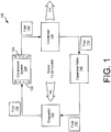
- the refrigeration system 100 may circulate a fluid 110 such as, for example, a liquid refrigerant in order to cool a space such as a room, home, or building.
- the circulated fluid 110 may absorb and remove heat from the space to be cooled and may subsequently reject the heat elsewhere.
- the refrigeration system 100 may include a compressor system 120, a condenser 130 coupled to the condenser system 120, an expansion valve 140 coupled to the condenser 130, and an evaporator 150 coupled between the compressor system 120 and the expansion valve 140.
- the compressor system 120 may include a suction port 122 and a discharge port 124.
- the suction port 122 of the compressor system 120 may receive the fluid 110 in a thermodynamic state known as a saturated vapor.
- the compressor system 120 may compress the fluid 110 as the compressor system 120 transfers the fluid 110 from the suction port 122 to the discharge port 124.
- the suction port 122 may receive the fluid 110 at a suction pressure and suction temperature.
- the compressor system 120 may compress the fluid 110 and may discharge the compressed fluid 110 via the discharge port 124 at a discharge pressure that is higher than the suction pressure. Compressing the fluid 110 may also result in the fluid 110 being discharged at a discharge temperature that is higher than the suction temperature.
- the fluid 110 discharged from the discharge port 124 may be in a thermodynamic state known as a superheated vapor. Accordingly, the fluid 110 discharged from the compressor system 120 may be at a temperature and pressure at which the fluid 110 may be readily condensed with cooling air or cooling liquid.
- the condenser 130 may be coupled to the discharge port 124 of the compressor system 120 to receive the fluid 110.
- the condenser 130 may cool the fluid 110 as the fluid 110 passes through the condenser 130 and may transform the fluid 110 from a superheated vapor to a saturated liquid.
- the condenser 130 may include coils or tubes through which the fluid 110 passes and across which cool air or cool liquid flows. As a result of the cool air or cool liquid passing across the coils of the condenser 130, the fluid 110 may reject or otherwise deliver heat from the refrigeration system 100 to the air or liquid which in turn carries the heat away.
- the expansion valve 140 may receive the fluid 110 from the condenser 130 in a thermodynamic state known as a saturated liquid.
- the expansion valve 140 may abruptly reduce the pressure of the fluid 110.
- the abrupt pressure reduction may cause adiabatic flash evaporation of at least a portion of the fluid 110 which may lower the temperature of the fluid 110.
- the adiabatic flash evaporation may result in a liquid and vapor mixture of the fluid 110 that has a temperature that is colder than the temperature of the space to be cooled.
- the evaporator 150 may receive the cold fluid 110 from the expansion valve 140 and may route the cold fluid 110 through coils or tubes of the evaporator 150.
- Warm air or liquid may be circulated from the space to be cooled across the coils or tubes of the evaporator 150.
- the warm air or liquid passing across the coils or tubes of the evaporator 150 may cause a liquid portion of the cold fluid 110 to evaporate.
- the warm air or liquid passed across the coils or tubes may be cooled by the fluid 110, thus lowering the temperature of the space to be cooled.
- the evaporator 150 may deliver the fluid 110 to the suction port 122 of the compressor system 120 as a saturated vapor.
- the evaporator 150 may complete the refrigeration cycle and may return the fluid 110 to the compressor system 120 to be recirculated again through the compressor system 120, condenser 130, and expansion valve 140. Therefore, in the refrigeration system 100, the evaporator 150 may absorb and remove heat from the space to be cooled, and the condenser 130 may subsequently reject the absorbed heat to air or liquid that carries the heat away from the space to be cooled.
- the compressor system 120 may include a controller 210, memory 220, an electric motor system 230, and a screw compressor 240.
- the compressor system 120 may further include one or more electrical sensors 250, torque sensors 255, suction pressure and/or temperature sensors 260, and discharge pressure and/or temperature sensors 270.
- the sensors 250, 255, 260, 270 provide status signals 290 with measurements that are indicative of the operation of the screw compressor 240.
- the controller 210 may include processors, microcontrollers, analog circuitry, digital circuitry, firmware, and/or software that cooperate to control operation of the screw compressor 240.
- the memory 220 may comprise non-volatile memory devices such as flash memory devices, read only memory (ROM) devices, electrically erasable/programmable ROM devices, and/or battery backed random access memory (RAM) devices to store an array of torque profiles 222 for the screw compressor 240 in a persistent manner.
- the memory 220 may further include instructions which the controller 210 may execute in order to control the operation of the screw compressor 240.
- the controller 210 may receive status signals 290 from one or more sensors 250, 255, 260, 270 of the compressor system 120 that provide information regarding operation of the screw compressor 240. Based upon the status signals 290, the controller 210 may determine an operating mode and/or operating point of the screw compressor 240 and may generate, based upon the determined operating mode and/or operating point, one or more command signals 212 to adjust the operation of the screw compressor 240. In particular, the controller 210 in one embodiment may select a torque profile 222 from the array of torque profiles 222 or may otherwise determine a torque profile 222 for the screw compressor 240 based upon the operating mode and/or operating point determined from the status signals 290. The controller 210 may then generate command signals 212 that request the electric motor system 230 to deliver torque 238 to the screw compressor 240 per the torque profile 222 obtained for the screw compressor 240.
- the electric motor system 230 may drive the screw compressor 240 in response to command signals 212 received from the controller 210.
- the electric motor system 230 may include a variable frequency drive 232 and an electric motor 234.
- the electric motor 234 may be coupled to the screw compressor 240 to drive meshed screw rotors 242, 244 of the screw compressor 240.
- the electric motor 234 may include a permanent magnetic motor that drives the rotors 242, 244 at a speed that is dependent upon the frequency of polyphase control signals 236 and at a torque 238 that is dependent upon the electric current supplied by the polyphase control signals 236.
- the variable frequency drive 232 may receive command signals 212 from the controller 210 and may generate the polyphase phase control signals 236.
- variable frequency drive 232 may adjust the frequency and electric current of the polyphase control signals 236 based upon the command signals 212 received from the controller 210.
- the controller 210 may generate the command signals 212 per a torque profile 222 selected for the screw compressor 240.
- the variable frequency drive 232 in response to the command signals 212 adjusts the frequency and current of the control signals 236 per the torque profile 222 selected for the screw compressor 240.
- the electrical sensor 250 may be positioned proximate the electric motor 234 to sense electrical operating characteristics of the electric motor 234.
- the electrical sensor 250 may further provide status signals 290 with measurements that are indicative of the sensed electrical operating characteristics.
- the electrical sensor 250 may include one or more current sensors.
- the current sensors may be positioned to sense the electric current supplied by the control signals 236 to the electric motor 234 and may generate status signals 290 that are indicative of the sensed electric current.
- the torque 238 produced by the electric motor 234 is dependent upon the electric current supplied by the control signals 236. Accordingly, status signals 290 indicative of the electric current supplied to the electric motor 234 may also be indicative of the torque 238 supplied by the electric motor 234.
- the electrical sensor 250 in one embodiment comprises current sensors that sense current supplied to the electric motor 234, the electrical sensor 250 may sense other electrical operating characteristics of the electric motor 234 such as voltages, currents, phase angles, effective impedances at the input and and/or other parts of the electric motor 234 and provide status signals 290 indicative of the sensed electrical operating characteristics.
- the torque sensor 255 may be positioned proximate the electric motor system 230 to sense torque 238 applied by the electric motor system 230 to the screw compressor 240.
- the torque sensor 255 may further provide status signals 290 with measurements that are indicative of the sensed torque 238.
- the torque sensor 255 may include one or more torsion elements positioned between the electric motor 234 and the compressor 240. The torque sensor 255 may then generate status signals 290 indicative of the torque 238 sensed by and/or applied to the torsion elements.
- the screw compressor 240 may further include the suction port 122 and the discharge port 124 of the compressor system 120.
- the suction pressure and/or temperature sensor 260 may be positioned proximate the suction port 122 of the screw compressor 240 to sense pressure and/or temperature of the fluid 110 entering the suction port 122.
- the discharge pressure and/or temperature sensor 270 may be positioned proximate the discharge port 124 of the screw compressor 240 to sense pressure and/or temperature of the fluid 110 discharged from the discharge port 124.
- the suction pressure and/or temperature sensor 260 may provide status signals 290 with measurements that are indicative of the sensed pressure and/or temperature of the fluid 110 entering the suction port 122
- the discharge pressure and/or temperature sensor 270 may provide status signals 290 with measurements that are indicative of the sensed pressure and/or temperature of the fluid 110 discharged from the discharge port 124.
- the screw compressor 240 may further include a plurality of meshed screw rotors 242, 244.
- the plurality of meshed screw rotors 242, 244 may define one or more compression pockets between the screw rotors 242, 244 and interior chamber walls of the screw compressor 240.
- Torque 238 supplied by the electric motor 234 may rotate the screw rotors 242, 244, thus closing the compression pocket from the suction port 122.
- Rotation of the screw rotors 242, 244 further decreases the volume of the compression pocket as the rotors 242, 244 move the fluid 110 toward the discharge port 124. Due to decreasing the volume of the compression pocket, the screw rotors 242, 244 deliver the fluid 110 to the discharge port 124 at an discharge pressure that is greater than the suction pressure and at a discharge temperature that is greater than the suction temperature.
- the operation of the screw compressor 240 in compressing and moving the fluid 110 produces axial and radial forces.
- the interaction of the screw rotors 242, 244, the axial forces, and the radial forces may result in time varying and non-uniform rotor movements and forces against chamber walls, bearings, and end surfaces of the screw compressor 240.
- Lubricating oil provides cushioning films for the chamber walls, rotors 242, 244, and bearings of the screw compressor 240, but does not prevent the transmission of the time varying and non-uniform axial and radial forces.
- the controller 210 attempts to select a torque profile 222 that drives the screw compressor 240 in a manner which reduces the non-productive radial and axial forces.
- Different screw compressor designs generally exhibit some unique operating characteristics and some common operating characteristics.
- a generally common operating characteristic of many screw compressor designs is that many screw compressor designs exhibit pulsating torque that is coincident with suction, compression, and discharge phases of the screw compressor.
- Other generally commonly operating characteristics include dynamic transmission of force from a male screw rotor to a meshed female screw rotor, and axial thrust of the screw rotors 242, 244.
- the screw compressor 222 may be operated at different speeds, average motor currents, discharge pressures and/or temperatures, suction pressures and/or temperatures, and/or other operating parameters to obtain beneficial torque profiles 222 for the screw compressor 240 in various operating modes and/or operating points.
- the screw compressor 240 may be operated in a start mode to obtain a starting torque profile 222, in an acceleration mode to obtain an acceleration torque profile 222, and in a deceleration mode to obtain a deceleration profile 222.
- each torque profile of the array of torque profiles 222 comprises a pattern of the electric motor to compressor shaft torque values occurring during one or several motor revolutions.
- the pattern may be repetitive and may be defined over more than one complete motor revolution as one revolution of the motor may not equate to one revolution of the compressor driven rotors 242, 244.
- the length of the torque profile 222 may be defined as an integer number of revolutions which make the torque profile pattern repeat in sequence.
- the controller 210 may repetitively select and/or apply a torque profile 222 to achieve a desired control result.
- the array of torque profiles 222 may be structured and torque profiles 222 may be selected by the controller 210 in manner that effects a stable control function of the screw compressor 240.
- the array of torque profiles 222 may be constructed to limit the rate at which the torque 238 is changed in order to maintain stability of the control function.
- stability may be maintained by populating the array of torque profiles 222 with torque profiles 222 that maintain approximately equal rates of change. This may be accomplished by experimental determination of operating conditions of the screw compressor 240 at unequal operating point differences, and maintaining the torque profile differences in the array of torque profiles 222 to approximately equal values.
- the torque profiles 222 may be constructed to represent the torque control values directly as sampled points versus time. In another embodiment, the torque profiles 222 may be constructed to represent torque control values as integer harmonic multiples of a primary operating frequency of the screw compressor 240. In particular, the harmonics defining the torque profiles 222 may be expressed in terms of harmonic frequency amplitude and phase.
- the controller 210 in one embodiment periodically executes the control method of FIG. 3 in order to adjust the torque profile 222 used to drive the screw compressor 240.
- the controller 210 may receive status signals 290 from various sensors 250, 255, 260, 270 of the compressors system 120 that provide information regarding the present operation of the screw compressor 240.
- the controller 210 at block 310 may determine whether the screw compressor 240 is in a start mode.
- the controller 210 may determine whether the screw compressor 240 is in a start mode based upon data supplied by the status signals 290.
- the controller 210 may also determine whether the screw compressor 240 is in a start mode based upon other data of the refrigeration system 100. For example, the controller 210 may determine that the screw compressor 240 is in a start mode in response to a signal from a control panel or thermostat (not shown) that indicates the controller 210 is to turn on the refrigeration system 100 and start the screw compressor 240. In response to determining that the screw compressor 240 is in a start mode, the controller 210 may select a start torque profile 222 from the memory 220 at block 315.
- the controller 210 at block 320 may determine whether the screw compressor 240 is accelerating. In particular, the controller 210 based upon the status signals 290 may determine whether the rotation speed of the meshed rotors 242, 244 is increasing. In one embodiment, the controller 210 determines whether the screw compressor 240 is accelerating based upon several sampled points of the status signals 290 as well as an acceleration threshold level to ensure that minor fluctuations in the rotation speed of the meshed rotors 242, 244 during periods of stable or steady operation are not mistakenly interpreted as an acceleration of the rotors 242, 244. In response to determining that the screw compressor 240 is accelerating, the controller 210 may select an acceleration torque profile 222 from the memory 220 at block 325.
- the controller 210 at block 330 may determine whether the screw compressor 240 is decelerating. In particular, the controller 210 based upon the status signals 290 may determine whether the rotation speed of the meshed rotors 242, 244 is decreasing. In one embodiment, the controller 210 determines whether the screw compressor 240 is decelerating based upon several sampled points of the status signals 290 as well as a deceleration threshold level to ensure that minor fluctuations in the rotation speed of the meshed rotors 242, 244 during periods of stable or steady operation are not mistakenly interpreted as a deceleration of the rotors 242, 244. In response to determining that the screw compressor 240 is decelerating, the controller 210 may select a deceleration torque profile 222 from the memory 220 at block 335.
- the controller 210 at block 340 may verify that the operation of the screw compressor 240 is relatively stable or steady.
- the screw compressor 240 may experience periods of relatively stable or steady operation in which the rotation speed of the rotors 242, 244 is relatively constant, the suction pressure and/or temperature is relatively constant, and the discharge pressure and/or temperature is relatively constant. Accordingly, the controller 210 at block 340 may determine based upon the status signals 290 whether the screw compressor 240 is operating at a relatively stable or steady operating point.
- the controller 210 may determine whether the screw compressor 240 is operating at a relatively stable or steady point based upon several sampled points of the status signals 290 as well as various threshold levels to ensure that minor fluctuations in the rotation speed, the suction pressure and/or temperature, and/or the discharge pressure and/or temperature do not result in a mistaken determination that the screw compressor 240 is not operating at a relatively stable or steady operating point.
- the controller 210 may select at 345 a default torque profile 222 for the screw compressor 240 that results in the electric motor system 230 providing suitable torque 238 to the screw compressor 240 during periods not associated with starting, accelerating, decelerating, and/or stable operation.
- the controller 210 at block 350 may determine an operating point of the screw compressor 240 based upon the status signals 290.
- the array of torque profiles 222 includes torque profiles 222 for the screw compressor 240 at various operating speeds, suction pressures and/or temperatures, and discharge pressures and/or temperatures.
- the controller 210 at block 355 may select, based upon the status signals 290, a torque profile 222 from the memory 220 that corresponds to the operating speed, suction pressure and/or temperature, and discharge pressure and/or temperature indicated by the status signals 290.
- the controller 210 may select a plurality of torque profiles 222 from the memory 220 that are near the operating point indicated by the status signals 290 and may generate through interpolation from the selected torque profiles 222 a torque profile 222 for the screw compressor 240 operating at the indicated operating point.
- the controller 210 may generate command signals 212 that request the electric motor system 230 to supply torque 238 to the screw compressor 240 per the torque profile 222 selected for the screw compressor 240.
- the screw compressor 240 generally exhibits pulsing torque due to the rotors 242, 244 receiving, compressing, and discharging fluid 110.
- the torque profiles 222 in one embodiment may be constructed to match the pulsing torque exhibited by the screw compressor 240. Accordingly, when switching from one torque profile 222 to another torque profile 222, the switch ideally is timed to coincide with the torque pulsations.
- the controller 210 generates the command signals 212 such that the electric motor system 230 effects the switch in torque profiles 222 in synchronization with the pulsing torque of the screw compressor 240.
- synchronization may be achieved using other techniques.
- the electric motor system 230 may sense the torque pulsations and switch the torque profiles 222 at an appropriate time.
Claims (15)
- Un système de compresseur (120) comprenant :un compresseur à vis (240) comprenant un orifice d'aspiration (122) pour recevoir un fluide à une pression d'aspiration, une pluralité de rotors à vis d'engrènement (242, 244) pour comprimer le fluide, et un port de déchargement (124) pour décharger le fluide comprimé à une pression de décharge supérieure à la pression d'aspiration ;un moteur électrique (234) pour recevoir les signaux de contrôle (236) et conduire la pluralité des rotors à vis d'engrènement (242, 244) à une vitesse par signaux de contrôle reçus ;un contrôleur (210) pour recevoir les signaux de statut (290) indicateurs d'un point de fonctionnement du compresseur à vis (240), pour sélectionner un profil de couple (222) pour le compresseur à vis (240) basé sur un point de fonctionnement du compresseur à vis, et pour générer des signaux de commande (212) qui demandent que le moteur électrique (234) soit conduit par le profil de couple sélectionné ; etune conduite à fréquence variable (232) pour recevoir les signaux de commande (212) et pour générer les signaux de contrôle (236) qui varient le couple entre le moteur électrique et le compresseur à vis par le profil de couple sélectionné, dans lequel le profil de couple sélectionné représente la variance dans le couple entre le moteur électrique (234) et le compresseur à vis (240) pendant un tour du moteur électrique.
- Un système de compresseur (120) de la revendication 1, comprenant par ailleurs une mémoire (220) comprenant une pluralité de profils de couple (222) dans lequel le contrôleur (210) doit sélectionner le profil de couple d'une pluralité de profils de couples basé sur le point de fonctionnement indiqué par les signaux de statut (290).
- Le système de compresseur (120) de la revendication 1, comprenant par ailleurs une mémoire (220) comprenant une pluralité de profils de couple (222), dans lequel en réponse aux signaux de statut (290) indiquant que le compresseur à vis (240) a atteint un point de fonctionnement relativement stable (240) basé sur la pluralité des profils de couple et le point de fonctionnement relativement stable indiqué par les signaux de statut (290).
- Le système de compresseur de la revendication 1, comprenant par ailleurs une mémoire (220) comprenant un profil de couple de départ, un profil de couple d'accélération, un profil de couple de décélération, un profil de couple par défaut, et une pluralité de profils de couple, dans lequel le contrôleur doit sélectionner le profil de couple à partir du profil de couple de départ, le profil de couple d'accélération, le profil de couple de décélération, le profil de couple par défaut, et la pluralité des profils de couple du point de fonctionnement basée sur les signaux de statut.
- Le système de compresseur (100) de la revendication 1, dans lequel
les signaux de contrôle comprennent des signaux de contrôle du courant alternatif polyphasé,
le moteur électrique (234) comprend un moteur magnétique permanent pour conduire le compresseur à vis (240) à une vitesse de conduite contrôlée par les signaux de contrôle du courant alternatif polyphasé, et
la conduite à fréquence variable (232) règle une fréquence des signaux de contrôle du courant alternatif polyphasé pour régler la vitesse de conduite du moteur magnétique permanent par les signaux de commande du contrôleur et le profil de couple sélectionné. - Le système de compresseur (120) de la revendication 1, comprenant par ailleurs un capteur d'orifice d'aspiration (260) à proximité de l'orifice d'aspiration (122) du compresseur à vis (240) pour fournir les signaux de statut avec les mesures de l'orifice d'aspiration du fluide pénétrant dans l'orifice d'aspiration du compresseur à vis,
un capteur de port de déchargement (270) à proximité du port de déchargement (124) du compresseur à vis (240) pour fournir les signaux de statut avec les mesures du port de déchargement du fluide déchargé à partir du port de déchargement du compresseur à vis, et
un capteur de couple (255) pour fournir les signaux de statut avec les mesures de couple du couple appliqué par le moteur électrique (234) au compresseur à vis (240), ou un ou plusieurs capteurs électriques positionnés à proximité du moteur électrique (234) pour capter les caractéristiques de fonctionnement du moteur électrique (234) et pour fournir les signaux de statut indicateurs des caractéristiques de fonctionnement électrique captées,
dans lequel le contrôleur (210) doit déterminer le point de fonctionnement du compresseur à vis (240) basé au moins sur les mesures de l'orifice d'aspiration, les mesures du port de déchargement, et les mesures du couple des signaux de statut ou les mesures du courant électrique. - Une méthode pour contrôler le fonctionnement d'un compresseur à vis (120) d'un système de réfrigération (100), comprenant
la réception des signaux de statut (305) concernant le fonctionnement du compresseur à vis du système de réfrigération ;
la sélection d'un point de fonctionnement (310, 320, 330, 340, 350) du compresseur à vis basé sur les signaux de statut reçus ;
la détermination d'un profil de couple (315, 325, 335, 345, 355) pour le compresseur à vis basé sur le point de fonctionnement dans lequel le couple représente une variance de couple entre le compresseur à vis pendant un tour de la pluralité de rotors à vis d'engrènement incluse dans le compresseur à vis ; et le réglage du couple appliqué au compresseur de couple par le profil de couple sélectionné. - La méthode de la revendication 7, comprenant par ailleurs la sélection d'un :profil de couple de départ (315) pour le compresseur à vis en réponse à la détermination que le compresseur à vis est sur le mode de démarrage ;un profil de couple d'accélération (325) pour le compresseur à vis en réponse à une vitesse croissante du compresseur à vis ;un profil de couple de décélération (335) pour le compresseur à vis en réponse à une vitesse décroissante du compresseur à vis ; etun profil de couple par défaut (345) en réponse à la détermination basée sur le signal de statut que le compresseur à vis ne fonctionne pas actuellement à un point de fonctionnement régulier ; etla conduite du compresseur à vis par le profil de couple de départ sélectionné, par le profil de couple d'accélération sélectionné, par le profil de couple de décélération sélectionné ou le profil de couple par défaut sélectionné.
- La méthode de la revendication 7, comprend par ailleurs la sélection du profil de couple en réponse à la détermination basée sur les signaux de statut que le compresseur à vis fonctionne actuellement à un point de fonctionnement relativement stable (340).
- La méthode de la revendication 7, comprenant par ailleurs la sélection du profil de couple en réponse aux mesures fournies par les signaux de statut atteignant un niveau de stabilité prédéterminé.
- Un système de réfrigération (100) comprenant
un compresseur à vis comprenant (120) un orifice d'aspiration (122) pour recevoir un fluide à une pression d'aspiration, une pluralité de rotors à vis d'engrènement (242, 244) pour comprimer le fluide, et un port de déchargement (124) pour décharger le fluide comprimé à une pression de décharge qui est supérieure à la pression d'aspiration ;
un condenseur (130) accouplé au port de déchargement (124) du compresseur à vis, le condenseur pour refroidir et condenser le fluide (110) reçu du port de déchargement (124) ;
une valve d'expansion (140) accouplée au condenseur (130), la valve d'expansion (140) pour évaporer au moins une portion du fluide (110) reçu du condenseur (130) en réduisant la pression du fluide reçu du condenseur ;
un évaporateur (150) accouplé à la valve d'expansion (140), l'évaporateur (150) pour évaporer le fluide reçu (110) de la valve d'expansion (140) et pour fournir le fluide à l'orifice d'aspiration (122) du compresseur à vis ;
un système à moteur électrique (232, 234) pour recevoir des signaux de commande (212) et pour conduire la pluralité des rotors à vis d'engrènement par les signaux de commande reçus ; et
un contrôleur (210) pour recevoir les signaux de statut (290) indicateurs d'un point de fonctionnement du compresseur à vis, pour sélectionner un profil de couple pour le compresseur à vis basé sur le point de fonctionnement du compresseur à vis, et pour générer des signaux de commande qui demandent au système du moteur électrique de varier le profil de couple entre le système du moteur électrique et le compresseur à vis par le profil de couple sélectionné,
dans lequel le profil de couple sélectionné représente la variance dans le couple entre le système du moteur électrique et le compresseur à vis pendant un tour du système du moteur électrique. - Le système de réfrigération (100) de la revendication 11, comprenant par ailleurs un capteur d'orifice d'aspiration (200) pour fournir les signaux de statut avec les mesures de l'orifice d'aspiration du fluide pénétrant dans l'orifice d'aspiration (122) du compresseur à vis ;
un capteur du port de déchargement (270) pour fournir les signaux de statut avec les mesures du port de déchargement du fluide déchargé depuis le port de déchargement (124) du compresseur à vis, et
un capteur de couple (255) pour fournir les signaux de statut avec les mesures de couple du couple appliqué par le système du moteur électrique au compresseur à vis,
dans lequel le contrôleur (210) doit déterminer le point de fonctionnement du compresseur à vis basé au moins sur les mesures de l'orifice d'aspiration, les mesures du port de déchargement, et les mesures du couple des signaux de statut. - Le système de réfrigération (210) de la revendication 11, dans lequel le système du moteur électrique comprend une conduite à fréquence variable (232) et un moteur magnétique permanent (234),
le moteur magnétique permanent (234) doit recevoir des signaux de contrôle à fréquence variable polyphasée et doit conduire la pluralité des rotors à vis d'engrènement (242, 244) par les signaux de contrôle à fréquence variable polyphasée reçus ;
la conduite à fréquence variable (232) doit recevoir les signaux de commande (212) et doit générer les signaux de contrôle à fréquence variable polyphasée (236) pour conduire le moteur magnétique permanent (234) par le profil de couple sélectionné. - Le système de réfrigération (100) de la revendication 13, comprenant par ailleurs un capteur d'orifice d'aspiration (260) pour fournir des signaux de statut avec des mesures de l'orifice d'aspiration du fluide pénétrant dans l'orifice d'aspiration (122) du compresseur à vis ;
un capteur du port de déchargement (270) pour fournir les signaux de statut avec les mesures du port de déchargement du fluide déchargé à partir du port de déchargement (124) du compresseur à vis ; et
un ou plusieurs capteurs pour capter le courant électrique fourni par les signaux de contrôle à fréquence variable polyphasée et pour fournir les signaux de statut avec des mesures du courant électrique des signaux de contrôle à fréquence variable polyphasée,
dans lequel le contrôleur (210) doit déterminer le point de fonctionnement du compresseur à vis basé au moins sur les mesures de l'orifice d'aspiration, les mesures du port de décharge, et les mesures du courant électrique. - Le système de réfrigération (100) de la revendication 13, comprenant par ailleurs une mémoire (220) comprenant une pluralité de profils de couple (222),
dans lequel le contrôleur (210) doit identifier le point de fonctionnement du compresseur à vis basé sur les signaux de statut (290), et doit sélectionner le profil de couple de la pluralité de profils de couple (222) sur la base du point de fonctionnement identifié.
Priority Applications (1)
| Application Number | Priority Date | Filing Date | Title |
|---|---|---|---|
| EP17184101.8A EP3269982B1 (fr) | 2009-08-20 | 2010-08-18 | Commande d'entraînement de compresseur à vis |
Applications Claiming Priority (2)
| Application Number | Priority Date | Filing Date | Title |
|---|---|---|---|
| US12/544,582 US8365544B2 (en) | 2009-08-20 | 2009-08-20 | Screw compressor drive control |
| PCT/US2010/045838 WO2011022455A2 (fr) | 2009-08-20 | 2010-08-18 | Commande de l'entraînement d'un compresseur à vis |
Related Child Applications (1)
| Application Number | Title | Priority Date | Filing Date |
|---|---|---|---|
| EP17184101.8A Division EP3269982B1 (fr) | 2009-08-20 | 2010-08-18 | Commande d'entraînement de compresseur à vis |
Publications (2)
| Publication Number | Publication Date |
|---|---|
| EP2467604A2 EP2467604A2 (fr) | 2012-06-27 |
| EP2467604B1 true EP2467604B1 (fr) | 2017-08-16 |
Family
ID=43604192
Family Applications (2)
| Application Number | Title | Priority Date | Filing Date |
|---|---|---|---|
| EP10748011.3A Active EP2467604B1 (fr) | 2009-08-20 | 2010-08-18 | Commande de l'entraînement d'un compresseur à vis |
| EP17184101.8A Active EP3269982B1 (fr) | 2009-08-20 | 2010-08-18 | Commande d'entraînement de compresseur à vis |
Family Applications After (1)
| Application Number | Title | Priority Date | Filing Date |
|---|---|---|---|
| EP17184101.8A Active EP3269982B1 (fr) | 2009-08-20 | 2010-08-18 | Commande d'entraînement de compresseur à vis |
Country Status (5)
| Country | Link |
|---|---|
| US (4) | US8365544B2 (fr) |
| EP (2) | EP2467604B1 (fr) |
| CN (2) | CN105485990B (fr) |
| CA (1) | CA2768560C (fr) |
| WO (1) | WO2011022455A2 (fr) |
Families Citing this family (16)
| Publication number | Priority date | Publication date | Assignee | Title |
|---|---|---|---|---|
| EP2341865A4 (fr) | 2008-10-07 | 2014-01-08 | Nanonerve Inc | Supports polymères fibreux multicouches, procédés de production et procédés d'utilisation |
| US8365544B2 (en) * | 2009-08-20 | 2013-02-05 | Trane International Inc. | Screw compressor drive control |
| JP2011246083A (ja) * | 2010-05-31 | 2011-12-08 | Suzuki Motor Corp | 車両用空調装置 |
| US10941770B2 (en) | 2010-07-20 | 2021-03-09 | Trane International Inc. | Variable capacity screw compressor and method |
| WO2013101701A1 (fr) | 2011-12-28 | 2013-07-04 | Carrier Corporation | Calcul de la pression de refoulement à partir d'un couple dans un système cvca |
| US9605886B2 (en) * | 2013-01-30 | 2017-03-28 | Trane International Inc. | Axial thrust control for rotary compressors |
| WO2014120651A1 (fr) * | 2013-01-30 | 2014-08-07 | Trane International Inc. | Commande de multiples charges permettant une atténuation d'harmoniques de variateur de fréquence électronique |
| CN103343743B (zh) * | 2013-07-16 | 2016-03-16 | 海信(山东)冰箱有限公司 | 一种变频与定速压缩机的自动识别方法及冰箱 |
| EP2853742B1 (fr) * | 2013-09-27 | 2016-04-20 | Emerson Climate Technologies GmbH | Procédé et appareil de détection d'huile dans un compresseur |
| AU2015344788B2 (en) | 2014-11-11 | 2020-03-12 | Trane International Inc. | Refrigerant compositions and methods of use |
| US9556372B2 (en) | 2014-11-26 | 2017-01-31 | Trane International Inc. | Refrigerant compositions |
| US10036325B2 (en) | 2016-03-30 | 2018-07-31 | General Electric Company | Variable flow compressor of a gas turbine |
| EP3485209B1 (fr) * | 2016-07-14 | 2021-12-08 | Carrier Corporation | Système de réfrigération de transport et procédé de commande |
| CN110195703A (zh) * | 2019-06-27 | 2019-09-03 | 西安交通大学 | 一种三电机驱动的单螺杆压缩机控制方法 |
| CN110219802A (zh) * | 2019-06-27 | 2019-09-10 | 西安交通大学 | 一种三电机驱动的单螺杆压缩机 |
| CN112066582B (zh) * | 2020-08-13 | 2022-01-28 | 珠海格力电器股份有限公司 | 一种直接蒸发式磁悬浮系统及具有它的空调器 |
Family Cites Families (20)
| Publication number | Priority date | Publication date | Assignee | Title |
|---|---|---|---|---|
| JPH0758069B2 (ja) * | 1983-09-09 | 1995-06-21 | 株式会社日立製作所 | 圧縮機のモータ制御装置 |
| US5067560A (en) | 1991-02-11 | 1991-11-26 | American Standard Inc. | Condenser coil arrangement for refrigeration system |
| US5832737A (en) | 1996-12-11 | 1998-11-10 | American Standard Inc. | Gas actuated slide valve in a screw compressor |
| US5979168A (en) | 1997-07-15 | 1999-11-09 | American Standard Inc. | Single-source gas actuation for screw compressor slide valve assembly |
| US6116046A (en) | 1999-03-05 | 2000-09-12 | American Standard Inc. | Refrigeration chiller with assured start-up lubricant supply |
| JP4330208B2 (ja) * | 1999-07-23 | 2009-09-16 | 東芝キヤリア株式会社 | 電動圧縮機の制御装置 |
| WO2003001067A1 (fr) * | 2001-06-21 | 2003-01-03 | Hitachi Construction Machinery Co., Ltd. | Unite hydraulique d'entrainement d'un engin et procede associe |
| JP4075338B2 (ja) * | 2001-07-18 | 2008-04-16 | 株式会社豊田自動織機 | 電動圧縮機の制御方法 |
| US6606872B1 (en) | 2002-05-20 | 2003-08-19 | American Standard International Inc. | Active refrigerant circuit using condenser fan of an inactive circuit |
| DE10258540A1 (de) * | 2002-12-14 | 2004-06-24 | Grasso Gmbh Refrigeration Technology | Schraubenverdichteraggregat mit Drehzahl-Drehmoment-Regelung |
| KR100525412B1 (ko) * | 2003-05-13 | 2005-11-02 | 엘지전자 주식회사 | 냉동 시스템의 압축기 제어 시스템 및 압축기의 제어방법 |
| JP4552388B2 (ja) * | 2003-05-28 | 2010-09-29 | パナソニック株式会社 | 圧縮機の運転制御方法、制御装置、冷媒圧縮機、及び冷凍装置 |
| US7387498B2 (en) * | 2003-12-04 | 2008-06-17 | York International Corporation | System and method for noise attenuation of screw compressors |
| JP2006017041A (ja) * | 2004-07-02 | 2006-01-19 | Kobe Steel Ltd | 回転式圧縮機 |
| US7413413B2 (en) * | 2004-07-20 | 2008-08-19 | York International Corporation | System and method to reduce acoustic noise in screw compressors |
| JP4580816B2 (ja) * | 2005-05-25 | 2010-11-17 | カルソニックカンセイ株式会社 | 可変容量コンプレッサのトルク算出装置およびトルク算出方法 |
| JP2006223097A (ja) * | 2006-04-21 | 2006-08-24 | Mitsubishi Electric Corp | 永久磁石形モータ、永久磁石形モータの制御方法、永久磁石形モータの制御装置、圧縮機、冷凍・空調装置。 |
| JP4297179B2 (ja) * | 2007-05-21 | 2009-07-15 | 株式会社デンソー | 圧縮機のトルク推定装置 |
| US7770806B2 (en) * | 2007-06-19 | 2010-08-10 | Nordyne Inc. | Temperature control in variable-capacity HVAC system |
| US8365544B2 (en) * | 2009-08-20 | 2013-02-05 | Trane International Inc. | Screw compressor drive control |
-
2009
- 2009-08-20 US US12/544,582 patent/US8365544B2/en active Active
-
2010
- 2010-08-18 EP EP10748011.3A patent/EP2467604B1/fr active Active
- 2010-08-18 WO PCT/US2010/045838 patent/WO2011022455A2/fr active Application Filing
- 2010-08-18 CA CA2768560A patent/CA2768560C/fr active Active
- 2010-08-18 CN CN201510982785.1A patent/CN105485990B/zh active Active
- 2010-08-18 EP EP17184101.8A patent/EP3269982B1/fr active Active
- 2010-08-18 CN CN201080037055.XA patent/CN102822528B/zh active Active
-
2013
- 2013-02-05 US US13/759,728 patent/US8875530B2/en active Active
-
2014
- 2014-11-04 US US14/532,241 patent/US9733002B2/en active Active
-
2017
- 2017-08-14 US US15/676,220 patent/US10352608B2/en active Active
Non-Patent Citations (1)
| Title |
|---|
| None * |
Also Published As
| Publication number | Publication date |
|---|---|
| US20150052921A1 (en) | 2015-02-26 |
| CN102822528B (zh) | 2016-01-20 |
| CA2768560A1 (fr) | 2011-02-24 |
| WO2011022455A3 (fr) | 2013-10-03 |
| EP3269982B1 (fr) | 2019-04-10 |
| CN102822528A (zh) | 2012-12-12 |
| US20130145787A1 (en) | 2013-06-13 |
| CA2768560C (fr) | 2016-03-22 |
| EP2467604A2 (fr) | 2012-06-27 |
| US9733002B2 (en) | 2017-08-15 |
| CN105485990B (zh) | 2019-04-30 |
| US8365544B2 (en) | 2013-02-05 |
| US20110041533A1 (en) | 2011-02-24 |
| CN105485990A (zh) | 2016-04-13 |
| US10352608B2 (en) | 2019-07-16 |
| US8875530B2 (en) | 2014-11-04 |
| EP3269982A1 (fr) | 2018-01-17 |
| WO2011022455A2 (fr) | 2011-02-24 |
| US20170343261A1 (en) | 2017-11-30 |
Similar Documents
| Publication | Publication Date | Title |
|---|---|---|
| US10352608B2 (en) | Screw compressor drive control | |
| EP0628149B1 (fr) | Systeme de commande pour systeme de climatisation/refrigeration | |
| US10544972B2 (en) | Refrigerator and control method therefor | |
| US6109048A (en) | Refrigerator having a compressor with variable compression capacity | |
| US10101070B2 (en) | Axial thrust control for rotary compressors | |
| US20110083450A1 (en) | Refrigerant System With Stator Heater | |
| US10753675B2 (en) | Refrigerator and method of controlling the same | |
| CN104792077B (zh) | 制冷设备及用于制冷设备的压缩机的开机控制方法、装置 | |
| CN104567155A (zh) | 空气调节器 | |
| BRPI0318601B1 (pt) | aparelho e método de controle de acionamento de compressor linear | |
| JP6076136B2 (ja) | 冷凍装置 | |
| KR20170072111A (ko) | 냉장고, 냉장고의 구동방법 및 컴퓨터 판독가능 기록매체 | |
| KR100931591B1 (ko) | 냉장고용 팬모터의 제어장치 | |
| KR100207087B1 (ko) | 냉장고의 구동제어방법 | |
| AU2015406080B2 (en) | Control method for a cooling device | |
| KR101660981B1 (ko) | 냉장고 및 냉장고의 제어방법 | |
| JP2010216678A (ja) | 冷凍装置 | |
| US20230383741A1 (en) | Method for determining a discharge pressure of a rolling piston compressor | |
| KR20060056511A (ko) | 공조기에서 인버터 압축기의 제어 방법 |
Legal Events
| Date | Code | Title | Description |
|---|---|---|---|
| PUAI | Public reference made under article 153(3) epc to a published international application that has entered the european phase |
Free format text: ORIGINAL CODE: 0009012 |
|
| 17P | Request for examination filed |
Effective date: 20120207 |
|
| AK | Designated contracting states |
Kind code of ref document: A2 Designated state(s): AL AT BE BG CH CY CZ DE DK EE ES FI FR GB GR HR HU IE IS IT LI LT LU LV MC MK MT NL NO PL PT RO SE SI SK SM TR |
|
| DAX | Request for extension of the european patent (deleted) | ||
| R17D | Deferred search report published (corrected) |
Effective date: 20131003 |
|
| GRAP | Despatch of communication of intention to grant a patent |
Free format text: ORIGINAL CODE: EPIDOSNIGR1 |
|
| STAA | Information on the status of an ep patent application or granted ep patent |
Free format text: STATUS: GRANT OF PATENT IS INTENDED |
|
| INTG | Intention to grant announced |
Effective date: 20170303 |
|
| GRAS | Grant fee paid |
Free format text: ORIGINAL CODE: EPIDOSNIGR3 |
|
| GRAA | (expected) grant |
Free format text: ORIGINAL CODE: 0009210 |
|
| STAA | Information on the status of an ep patent application or granted ep patent |
Free format text: STATUS: THE PATENT HAS BEEN GRANTED |
|
| AK | Designated contracting states |
Kind code of ref document: B1 Designated state(s): AL AT BE BG CH CY CZ DE DK EE ES FI FR GB GR HR HU IE IS IT LI LT LU LV MC MK MT NL NO PL PT RO SE SI SK SM TR |
|
| REG | Reference to a national code |
Ref country code: GB Ref legal event code: FG4D |
|
| REG | Reference to a national code |
Ref country code: FR Ref legal event code: PLFP Year of fee payment: 8 |
|
| REG | Reference to a national code |
Ref country code: CH Ref legal event code: EP |
|
| REG | Reference to a national code |
Ref country code: IE Ref legal event code: FG4D |
|
| REG | Reference to a national code |
Ref country code: AT Ref legal event code: REF Ref document number: 919338 Country of ref document: AT Kind code of ref document: T Effective date: 20170915 |
|
| REG | Reference to a national code |
Ref country code: DE Ref legal event code: R096 Ref document number: 602010044443 Country of ref document: DE |
|
| REG | Reference to a national code |
Ref country code: NL Ref legal event code: MP Effective date: 20170816 |
|
| REG | Reference to a national code |
Ref country code: LT Ref legal event code: MG4D |
|
| REG | Reference to a national code |
Ref country code: AT Ref legal event code: MK05 Ref document number: 919338 Country of ref document: AT Kind code of ref document: T Effective date: 20170816 |
|
| PG25 | Lapsed in a contracting state [announced via postgrant information from national office to epo] |
Ref country code: NL Free format text: LAPSE BECAUSE OF FAILURE TO SUBMIT A TRANSLATION OF THE DESCRIPTION OR TO PAY THE FEE WITHIN THE PRESCRIBED TIME-LIMIT Effective date: 20170816 Ref country code: AT Free format text: LAPSE BECAUSE OF FAILURE TO SUBMIT A TRANSLATION OF THE DESCRIPTION OR TO PAY THE FEE WITHIN THE PRESCRIBED TIME-LIMIT Effective date: 20170816 Ref country code: LT Free format text: LAPSE BECAUSE OF FAILURE TO SUBMIT A TRANSLATION OF THE DESCRIPTION OR TO PAY THE FEE WITHIN THE PRESCRIBED TIME-LIMIT Effective date: 20170816 Ref country code: HR Free format text: LAPSE BECAUSE OF FAILURE TO SUBMIT A TRANSLATION OF THE DESCRIPTION OR TO PAY THE FEE WITHIN THE PRESCRIBED TIME-LIMIT Effective date: 20170816 Ref country code: SE Free format text: LAPSE BECAUSE OF FAILURE TO SUBMIT A TRANSLATION OF THE DESCRIPTION OR TO PAY THE FEE WITHIN THE PRESCRIBED TIME-LIMIT Effective date: 20170816 Ref country code: FI Free format text: LAPSE BECAUSE OF FAILURE TO SUBMIT A TRANSLATION OF THE DESCRIPTION OR TO PAY THE FEE WITHIN THE PRESCRIBED TIME-LIMIT Effective date: 20170816 Ref country code: NO Free format text: LAPSE BECAUSE OF FAILURE TO SUBMIT A TRANSLATION OF THE DESCRIPTION OR TO PAY THE FEE WITHIN THE PRESCRIBED TIME-LIMIT Effective date: 20171116 |
|
| PG25 | Lapsed in a contracting state [announced via postgrant information from national office to epo] |
Ref country code: LV Free format text: LAPSE BECAUSE OF FAILURE TO SUBMIT A TRANSLATION OF THE DESCRIPTION OR TO PAY THE FEE WITHIN THE PRESCRIBED TIME-LIMIT Effective date: 20170816 Ref country code: IS Free format text: LAPSE BECAUSE OF FAILURE TO SUBMIT A TRANSLATION OF THE DESCRIPTION OR TO PAY THE FEE WITHIN THE PRESCRIBED TIME-LIMIT Effective date: 20171216 Ref country code: ES Free format text: LAPSE BECAUSE OF FAILURE TO SUBMIT A TRANSLATION OF THE DESCRIPTION OR TO PAY THE FEE WITHIN THE PRESCRIBED TIME-LIMIT Effective date: 20170816 Ref country code: BG Free format text: LAPSE BECAUSE OF FAILURE TO SUBMIT A TRANSLATION OF THE DESCRIPTION OR TO PAY THE FEE WITHIN THE PRESCRIBED TIME-LIMIT Effective date: 20171116 Ref country code: GR Free format text: LAPSE BECAUSE OF FAILURE TO SUBMIT A TRANSLATION OF THE DESCRIPTION OR TO PAY THE FEE WITHIN THE PRESCRIBED TIME-LIMIT Effective date: 20171117 Ref country code: PL Free format text: LAPSE BECAUSE OF FAILURE TO SUBMIT A TRANSLATION OF THE DESCRIPTION OR TO PAY THE FEE WITHIN THE PRESCRIBED TIME-LIMIT Effective date: 20170816 |
|
| REG | Reference to a national code |
Ref country code: CH Ref legal event code: PL |
|
| PG25 | Lapsed in a contracting state [announced via postgrant information from national office to epo] |
Ref country code: RO Free format text: LAPSE BECAUSE OF FAILURE TO SUBMIT A TRANSLATION OF THE DESCRIPTION OR TO PAY THE FEE WITHIN THE PRESCRIBED TIME-LIMIT Effective date: 20170816 Ref country code: CZ Free format text: LAPSE BECAUSE OF FAILURE TO SUBMIT A TRANSLATION OF THE DESCRIPTION OR TO PAY THE FEE WITHIN THE PRESCRIBED TIME-LIMIT Effective date: 20170816 Ref country code: CH Free format text: LAPSE BECAUSE OF NON-PAYMENT OF DUE FEES Effective date: 20170831 Ref country code: LI Free format text: LAPSE BECAUSE OF NON-PAYMENT OF DUE FEES Effective date: 20170831 Ref country code: DK Free format text: LAPSE BECAUSE OF FAILURE TO SUBMIT A TRANSLATION OF THE DESCRIPTION OR TO PAY THE FEE WITHIN THE PRESCRIBED TIME-LIMIT Effective date: 20170816 |
|
| REG | Reference to a national code |
Ref country code: BE Ref legal event code: MM Effective date: 20170831 |
|
| REG | Reference to a national code |
Ref country code: DE Ref legal event code: R097 Ref document number: 602010044443 Country of ref document: DE |
|
| REG | Reference to a national code |
Ref country code: IE Ref legal event code: MM4A |
|
| PG25 | Lapsed in a contracting state [announced via postgrant information from national office to epo] |
Ref country code: EE Free format text: LAPSE BECAUSE OF FAILURE TO SUBMIT A TRANSLATION OF THE DESCRIPTION OR TO PAY THE FEE WITHIN THE PRESCRIBED TIME-LIMIT Effective date: 20170816 Ref country code: SK Free format text: LAPSE BECAUSE OF FAILURE TO SUBMIT A TRANSLATION OF THE DESCRIPTION OR TO PAY THE FEE WITHIN THE PRESCRIBED TIME-LIMIT Effective date: 20170816 Ref country code: IT Free format text: LAPSE BECAUSE OF FAILURE TO SUBMIT A TRANSLATION OF THE DESCRIPTION OR TO PAY THE FEE WITHIN THE PRESCRIBED TIME-LIMIT Effective date: 20170816 Ref country code: SM Free format text: LAPSE BECAUSE OF FAILURE TO SUBMIT A TRANSLATION OF THE DESCRIPTION OR TO PAY THE FEE WITHIN THE PRESCRIBED TIME-LIMIT Effective date: 20170816 Ref country code: MC Free format text: LAPSE BECAUSE OF FAILURE TO SUBMIT A TRANSLATION OF THE DESCRIPTION OR TO PAY THE FEE WITHIN THE PRESCRIBED TIME-LIMIT Effective date: 20170816 |
|
| PLBE | No opposition filed within time limit |
Free format text: ORIGINAL CODE: 0009261 |
|
| STAA | Information on the status of an ep patent application or granted ep patent |
Free format text: STATUS: NO OPPOSITION FILED WITHIN TIME LIMIT |
|
| PG25 | Lapsed in a contracting state [announced via postgrant information from national office to epo] |
Ref country code: LU Free format text: LAPSE BECAUSE OF NON-PAYMENT OF DUE FEES Effective date: 20170818 |
|
| REG | Reference to a national code |
Ref country code: FR Ref legal event code: PLFP Year of fee payment: 9 |
|
| 26N | No opposition filed |
Effective date: 20180517 |
|
| PG25 | Lapsed in a contracting state [announced via postgrant information from national office to epo] |
Ref country code: IE Free format text: LAPSE BECAUSE OF NON-PAYMENT OF DUE FEES Effective date: 20170818 |
|
| PG25 | Lapsed in a contracting state [announced via postgrant information from national office to epo] |
Ref country code: SI Free format text: LAPSE BECAUSE OF FAILURE TO SUBMIT A TRANSLATION OF THE DESCRIPTION OR TO PAY THE FEE WITHIN THE PRESCRIBED TIME-LIMIT Effective date: 20170816 Ref country code: BE Free format text: LAPSE BECAUSE OF NON-PAYMENT OF DUE FEES Effective date: 20170831 |
|
| PG25 | Lapsed in a contracting state [announced via postgrant information from national office to epo] |
Ref country code: MT Free format text: LAPSE BECAUSE OF NON-PAYMENT OF DUE FEES Effective date: 20170818 |
|
| PG25 | Lapsed in a contracting state [announced via postgrant information from national office to epo] |
Ref country code: HU Free format text: LAPSE BECAUSE OF FAILURE TO SUBMIT A TRANSLATION OF THE DESCRIPTION OR TO PAY THE FEE WITHIN THE PRESCRIBED TIME-LIMIT; INVALID AB INITIO Effective date: 20100818 |
|
| PG25 | Lapsed in a contracting state [announced via postgrant information from national office to epo] |
Ref country code: CY Free format text: LAPSE BECAUSE OF NON-PAYMENT OF DUE FEES Effective date: 20170816 |
|
| PG25 | Lapsed in a contracting state [announced via postgrant information from national office to epo] |
Ref country code: MK Free format text: LAPSE BECAUSE OF FAILURE TO SUBMIT A TRANSLATION OF THE DESCRIPTION OR TO PAY THE FEE WITHIN THE PRESCRIBED TIME-LIMIT Effective date: 20170816 |
|
| PG25 | Lapsed in a contracting state [announced via postgrant information from national office to epo] |
Ref country code: TR Free format text: LAPSE BECAUSE OF FAILURE TO SUBMIT A TRANSLATION OF THE DESCRIPTION OR TO PAY THE FEE WITHIN THE PRESCRIBED TIME-LIMIT Effective date: 20170816 |
|
| PG25 | Lapsed in a contracting state [announced via postgrant information from national office to epo] |
Ref country code: PT Free format text: LAPSE BECAUSE OF FAILURE TO SUBMIT A TRANSLATION OF THE DESCRIPTION OR TO PAY THE FEE WITHIN THE PRESCRIBED TIME-LIMIT Effective date: 20170816 |
|
| PG25 | Lapsed in a contracting state [announced via postgrant information from national office to epo] |
Ref country code: AL Free format text: LAPSE BECAUSE OF FAILURE TO SUBMIT A TRANSLATION OF THE DESCRIPTION OR TO PAY THE FEE WITHIN THE PRESCRIBED TIME-LIMIT Effective date: 20170816 |
|
| REG | Reference to a national code |
Ref country code: DE Ref legal event code: R082 Ref document number: 602010044443 Country of ref document: DE Representative=s name: HL KEMPNER PATENTANWAELTE, SOLICITORS (ENGLAND, DE Ref country code: DE Ref legal event code: R082 Ref document number: 602010044443 Country of ref document: DE Representative=s name: HL KEMPNER PATENTANWALT, RECHTSANWALT, SOLICIT, DE |
|
| P01 | Opt-out of the competence of the unified patent court (upc) registered |
Effective date: 20230511 |
|
| PGFP | Annual fee paid to national office [announced via postgrant information from national office to epo] |
Ref country code: GB Payment date: 20230720 Year of fee payment: 14 |
|
| PGFP | Annual fee paid to national office [announced via postgrant information from national office to epo] |
Ref country code: FR Payment date: 20230720 Year of fee payment: 14 Ref country code: DE Payment date: 20230720 Year of fee payment: 14 |