EP2466291B1 - Cuvette for photometric measurement of small liquid volumes - Google Patents
Cuvette for photometric measurement of small liquid volumes Download PDFInfo
- Publication number
- EP2466291B1 EP2466291B1 EP11192461.9A EP11192461A EP2466291B1 EP 2466291 B1 EP2466291 B1 EP 2466291B1 EP 11192461 A EP11192461 A EP 11192461A EP 2466291 B1 EP2466291 B1 EP 2466291B1
- Authority
- EP
- European Patent Office
- Prior art keywords
- cuvette
- plane
- radius
- inner edges
- front wall
- Prior art date
- Legal status (The legal status is an assumption and is not a legal conclusion. Google has not performed a legal analysis and makes no representation as to the accuracy of the status listed.)
- Active
Links
Images


Classifications
-
- G—PHYSICS
- G01—MEASURING; TESTING
- G01N—INVESTIGATING OR ANALYSING MATERIALS BY DETERMINING THEIR CHEMICAL OR PHYSICAL PROPERTIES
- G01N21/00—Investigating or analysing materials by the use of optical means, i.e. using sub-millimetre waves, infrared, visible or ultraviolet light
- G01N21/01—Arrangements or apparatus for facilitating the optical investigation
- G01N21/03—Cuvette constructions
- G01N2021/0378—Shapes
Definitions
- This invention relates to the field of optical cuvettes for photometric measurement of liquids in an optical system, wherein the cuvette comprises an upper part and a measurement chamber at the bottom.
- the invention relates also to an optical system comprising said cuvette and a method of using said cuvette in the optical system.
- Various types of tests related to patient diagnosis and therapy can be performed by analysis of a patient's fluid sample.
- patient samples are typically placed in sample vials, extracted from the vials, combined with various reagents in special reaction cuvettes, incubated, and analyzed.
- one or more assay reagents are added to a liquid sample, the sample-reagent combination is mixed and incubated within a reaction cuvette.
- Photometric measurements using a beam of light illuminating the sample-reagent combinations in such reaction cuvettes are made from which an amount of analyte may be determined using known techniques. Examples of such photometric measurements comprise turbidimetric, fluorometric and absorption measurements or the like.
- EP1898202A1 discloses a stirring container comprising different recess portions and which is adapted as a cuvette for photometric measurement of liquid contained therein.
- the present invention provides a cuvette, which enables reliable and reproducible photometric measurement of small volumes of liquids. This is achieved by an optimized geometry of the cuvette and of a measurement chamber contained therein, which allows to maximize the measurement volume.
- An advantage of the present invention is that by enabling operation with smaller volumes, it also enables more tests per sample volume, or enables to run a test when sample availability is limited. Another advantage of the present invention is the induced consumption of reagents, meaning lower costs per test and less waste, with benefits for the user and the environment. Also, by reducing sample and reagent volumes, reactions may reach completion more rapidly, thus reducing turn-around time. Another advantage of the present invention is that for reactions requiring heat, equilibration of temperature throughout the sample volume is quick, due to minimized thermal time constants and thermal gradients across the sample. Thus throughput is also increased.
- the present invention refers to a cuvette for photometric measurement of liquids.
- the cuvette comprises a body having outer walls and an inner space for receiving liquids.
- the body comprises an upper part.
- the upper part comprises an upper open top portion for allowing liquids to be introduced in the cuvette and an inner surface having in a plane A-A a first annular cross-section or substantially rectangular cross-section with four upper inner edges, the upper inner edges extending from the plane A-A to the upper open top portion.
- the body further comprises a lower measurement chamber.
- the lower measurement chamber comprises a lower closed bottom poition, a lower front wall, a lower back wall, two lower side walls, said lower walls forming four lower inner edges and a lower open top portion with a second substantially rectangular cross-section in a plane B-B smaller than the first annular or substantially rectangular cross-section in the plane A-A.
- the lower front wall and the lower back wall have portions, which are substantially planar and substantially parallel to each other.
- the body further comprises an abrupt transition zone between the upper part and the lower measurement chamber, i.e. between the plane A-A and the plane B-B wherein the plane A-A is different from the plane B-B.
- the transition zone comprises four transition inner edges connecting the four lower inner edges to the upper part.
- substantially rectangular comprises the term “substantially squared” and is herein used to indicate a geometry formed by at least four edges, at least two of which comprising at least a portion being straight and parallel to each other and wherein at least at the corners the geometry may be smoothed, e.g. present a curvature or radius.
- annular refers primarily to a circular or elliptical geometry and more generally to any area defined by an edgeless curved closed line.
- substantially planar and substantially parallel refer to surfaces intended to be flat and parallel to each other but which, e.g. because of manufacturing tolerances or because of manufacturing processes, may slightly present a curvature or be slightly inclined with respect to each other.
- a “measurement chamber” is a recess intended for receiving a volume of liquid approximately corresponding to its inner volume and adapted for the photometric measurement of this liquid.
- the liquid may be introduced in one or more steps. For example, a volume of sample approximately corresponding to the volume of the recess may be introduced for being analyzed as such. Alternatively, smaller volumes of one or more samples and one or more reagents may be introduced so that the total volume approximately corresponds to the volume of the recess.
- the measurement chamber is a liquid confinement chamber designed for receiving a pre-defined total volume of liquid and is optimized for operating with such a predefined volume of liquid. According to a preferred embodiment the measurement chamber has a volume smaller than 50 ⁇ L and most preferably in a range between 20 and 30 ⁇ L, e.g. about 25 ⁇ L.
- the liquid fills the measurement chamber with a flat upper surface laying in the plane B-B.
- the term "approximately” here refers to deviations from this ideal status, wherein due to surface energy, i.e. capillary forces, a meniscus is typically formed.
- the meniscus may be below or above the plane B-B depending on the wettability of the cuvette material by the liquid and thus depending on the liquid and on the cuvette material. Thus, either a slightly smaller volume or larger volume of liquid may be introduced with respect to the volume of the recess.
- One effect of the design of the cuvette according to the invention is to minimize such deviations of the location of the meniscus. This means that the effect is to minimize the meniscus such that the minimum or maximum of the meniscus is closer to the plane B-B and thus even volumes of liquid smaller than 50 ⁇ L can be reliably subjected to photometric measurement.
- the cuvette such that, at least in the plane B-B the lower inner edges are sharp or comprise fillets having a first radius, and in the plane A-A the first annular cross-section has a second radius or the upper inner edges comprise fillets having a second radius, the second radius being larger than the first radius.
- the transition inner edges comprise fillets having a gradually increasing radius passing from the sharp edges or the first radius of the lower inner edges in the plane B-B to the second radius of the first annular cross-section or of the upper inner edges in the plane A-A.
- sharp means that the lower walls converge into a line edge or into an only minimally rounded edge, e.g. due to manufacturing tolerances or processes. Since, at the microscopic level there is always a first radius at the lower inner edges, according to the present invention an edge is regarded to be sharp when it has a radius below 0.01 mm.
- the effect of being sharp is an increased capillary effect, i.e. an enhanced tendency of the typically used liquids (aqueous solutions) to rise along the edge. Thus, the sharper is an edge the higher is the capillary effect.
- smooth or curved edges i.e. for edges with larger radius.
- the term "fillet” is here used to indicate a more discernible curvature at the edge having a certain radius like if material was added on an imaginary edge line to make the edge smoother rather than sharp. The presence of a fillet is sometimes unavoidable for manufacturing or cost reasons.
- radius of an edge or a fillet refers to the radius of an osculating circle symmetrically laying between two adjacent walls and whose curvature matches the curvature of the edge most tightly. In particular, it is the radius of that circle, which among all substantially tangent circles at that given position has substantially the same curvature as the edge.
- first cross-section in the plane A-A is larger than the second cross-section in the plane B-B and that the second radius is larger than the first radius.
- transition inner edges comprise fillets having a gradually increasing radius passing from the plane B-B to the plane A-A within a short distance.
- the distance between the plane A-A and B-B is short compared to the distance between the plane A-A and the upper open top portion and compared to the distance between the plane B-B and the lower closed bottom portion.
- the plane A-A is always different from the plane B-B, that is the distance between the plane A-A and the plane B-B is always greater than zero.
- the cuvette so that when a predefined-volume of liquid is introduced, a meniscus is formed which is just below the plane B-B and an energy level is reached which is sufficiently below the energy barrier, is preferred.
- the cuvette may be designed such that when a predefined-volume of liquid is introduced the minimum of the meniscus is stopped at a distance from the plane B-B which is less than 20% of the distance between the plane B-B and the lower closed bottom portion.
- Fixing of the meniscus at plane B-B prevents that liquid volume is lost into the transition zone and upper part, which would reduce the volume in the lower measurement chamber, which is needed for the photometric measurement. Measurement thus can be enabled even with smaller volumes of liquid.
- the energy level is such that losses of liquid from the measurement chamber are minimized even when moving the cuvette and/or when mixing the liquid in the measurement chamber, e.g. by stirring, by using ultrasound or shaking.
- having the plane A-A and the plane B-B in different planes respectively in other words by having an inclined transition zone, has the further advantage that liquid eventually escaped from the measurement chamber, e.g. during mixing, can more easily return to the measurement chamber. If the transition zone was flat, that is if the plane A-A and the plane B-B were on the same plane, liquid escaped from the measurement chamber onto the flat transition zone would be retained there and thus permanently lost without the possibility to return to the measurement chamber.
- the upper part of the cuvette has a tapered shape with a cross-section, which is gradually increasing from the plane A-A to the top open portion.
- the upper inner edges comprise fillets having a constant second radius between the plane A-A and the top open portion.
- the upper inner edges comprise fillets having a second radius, which is gradually increasing from the plane A-A to the open top portion.
- the open top portion has a substantially circular or elliptical cross-section.
- the cross-section of the upper part and/or the size of the second radius above the plane A-A may play a role other than that described above with relation to the surface energy. This role may be related e.g. to easier and/or cheaper manufacturing or to more convenient use of the cuvette, e.g. when introducing a liquid or when handling a cuvette.
- the lower front wall and the lower back wall have a substantially rectangular area comprising corners with a curved shape in proximity of the lower closed bottom portion.
- At least the lower front wall and the lower back wall are optically transparent.
- the cuvette in proximity of the open top portion comprises at least one lip projecting outwards of the cuvette body. This lip may be convenient when handling the cuvette and/or for holding the cuvette in a cuvette holding position of an optical system and/or for aligning the cuvette in an optical system.
- a cuvette is manufactured in one piece of injection moulded polymeric material.
- a product comprising a plurality of cuvettes, arranged e.g. as an array of cuvettes next to each other side by side, joined e.g. by a strip or common lip in the upper part, is manufactured in one piece of injection moulded polymeric material.
- the present invention also refers to an optical system for photometric measurement of liquids.
- the system comprises a plurality of cuvettes according to any of the above embodiments, a light source providing a light beam, and an optical detector.
- the system further comprises a control unit being set up to bring one cuvette at a time in optical alignment with the light source and the detector so that the lower front wall faces the light source and the lower back wall faces the optical detector.
- an optical system is either a separate unit or an integrated component or module within an analytical instrument.
- the optical system makes it possible to guide light in a controlled manner through a sample located in the measurement chamber of the cuvette, and to measure changes in optical transmission, such as absorbance and scattering, for the optical analysis of analytes present in the sample.
- the optical system may be however configured to carry out in addition other spectroscopic measurements. It may also entail temporally static measurements, time resolved measurements, or both.
- the system may comprise a cuvette holding unit for holding comprising at least one cuvette holding position.
- the cuvette holding unit may be embodied as a conveyor, e.g. a linear or rotor-like conveyor, moving in at least one direction or as a robotic arm capable of performing movements, driven by one or more electrical motors.
- the cuvette holding unit comprises an array of cuvette holding positions, the cuvette holding positions being located in the optical path one at a time according to an established assay sequence.
- the cuvette holding unit is assembled as a rotor comprising a plurality of cuvette holding positions to receive a plurality of cuvettes and to bring one cuvette at a time in the optical path, i.e. in optical alignment with the light source and the detector.
- the optical system is particularly suitable for analyzing biological samples.
- Samples are preferably liquid solutions in which one or more analytes of interest can be potentially found, such as body fluids like blood, serum, plasma, urine, milk, saliva, cerebrospinal fluid, etc...
- Samples may be analyzed as such or after being diluted with another solution or after having being mixed with reagents e.g. to carry out one or more diagnostic assays like e.g. clinical chemistry assays and immunoassays.
- the optical system may advantageously be used in the performance of scattering assays to detect the result of a chemical or biological reaction or to monitor the progress of a chemical or biological reaction, e.g. in a coagulation assay, agglutination assay, turbidimetric assay.
- a light source according to the invention is a unit within the optical system capable of emitting a light beam in a usable wavelength range.
- the term "usable” refers to a selected wavelength or wavelength range, at which light guided through a sample can be used to measure analyte concentrations present in the sample.
- the light source comprises at least one light emitting element.
- a light emitting element is an electric powered radiation source such as an incandescent lamp, an electroluminescent lamp, a gas discharge lamp, a high-intensity discharge lamp, a laser.
- the at least one light emitting element is for example a halogen lamp, which like all incandescent light bulbs, produces a continuous broad spectrum of light, from near ultraviolet to far infrared.
- the at least one light emitting element is a light emitting diode or "LED".
- the light beam has a curved shape divided in four symmetric sectors, each sector having a shape substantially matching the shape of the corners of the cuvette in proximity of the lower closed bottom portion.
- the light beam has an area of intersection with the lower front wall which is between 2 and 10 times smaller than the area of the lower front wall.
- An optical detector is a photodetector, which is a device that converts electro-magnetic energy into an electrical signal, including both single element and multi-element or array optical detectors.
- an optical detector is a device capable of monitoring an optical electro-magnetic signal and providing an electrical output signal or response signal relative to a baseline signal indicative of the presence and/or concentration of an analyte in a sample being located in the optical path.
- Such devices include, for example, photodiodes, including avalanche photodiodes, phototransistors, photoconductive detectors, linear sensor arrays, CCD detectors, CMOS optical detectors, including CMOS array detectors, photomultipliers, and photomultiplier arrays.
- an optical detector such as a photodiode or photomultiplier, may contain additional signal conditioning or processing electronics.
- an optical detector may include at least one pre-amplifier, electronic filter, or integrating circuit. Suitable pre-preamplifiers include integrating, transimpedance, and current gain (current mirror) pre-amplifiers.
- the detector is of the CCD or CMOS type.
- the detector is of the photodiode or PMT type.
- the control unit may be embodied as programmable logic controller running a computer-readable program provided with instructions to perform operations in accordance with a process operation plan.
- An analytical instrument is an apparatus assisting users with the detection, e.g. qualitative and/or quantitative optical evaluation of samples for diagnostic purpose.
- Examples of such an instrument are: a clinical chemistry analyzer, a coagulation chemistry analyzer, an immunochemistry analyzer, a urine analyzer, either as self-standing instrument or module within a system comprising a plurality of said modules, used to detect the result of chemical or biological reactions or to monitor the progress of chemical or biological reactions.
- the instrument may comprise units assisting with the pipetting, dosing, mixing of samples and/or reagents, units for loading and/or unloading and/or transporting and/or storing sample tubes or racks comprising sample tubes, units for loading and/or unloading and/or transporting and/or storing reagent containers or cassettes.
- the analyzer may also comprise identification units comprising sensors, e.g. barcode readers. Alternative technologies such as RFID may also be used for identification.
- the instrument further comprises a sample receiving unit for receiving samples to be assayed.
- Samples may be received for example in the form of tubes, e.g. blood collection tubes, or smaller tubes or vessels comprising sample aliquots. Samples may be arranged in single carriers or holders or racks for multiple samples.
- the instrument further comprises a reagent holding unit for holding reagents to perform the assays.
- Reagents may be arranged for example in the form of containers or cassettes containing individual reagents or group of reagents, placed in appropriate receptacles or positions within a storage compartment or conveyor.
- the instrument further comprises a cuvette feeding unit for feeding cuvettes to the cuvette holding unit.
- the instrument further comprises one or more liquid processing units, e.g. a pipetting unit, to deliver samples and/or reagents to optical cuvettes.
- the pipetting unit may comprise a reusable washable needle, e.g. a steel needle, or disposable pipette tips.
- the pipetting unit is operatively coupled to an automated positioning device for moving the pipette tip or needle with respect to the instrument and, e.g., may be mounted to a transfer head that can be moved in two directions of travel in a plane, e.g., by means of guiding rails and a third direction of travel orthogonal to the plane, e.g., by means of a spindle drive.
- the instrument may further comprise one or more incubation units for maintaining sample/reagent mixtures at a certain temperature during reaction, wash stations for washing pipette tips or needles, mixing paddles, etc...
- the instrument may further comprise mixing one or more mixing units, comprising e.g. a shaker to shake a cuvette comprising a liquid or a mixing paddle to mix liquids in a cuvette or reagent container or an ultrasound generator.
- mixing one or more mixing units comprising e.g. a shaker to shake a cuvette comprising a liquid or a mixing paddle to mix liquids in a cuvette or reagent container or an ultrasound generator.
- the instrument is being set up for controlling pipetting in the lower measurement chamber of a pre-defined volume of liquid or for adding one or more liquids until a pre-defined volume of liquid is reached, which nearly corresponds to the inner volume of the lower measurement chamber.
- a pre-defined volume of liquid which nearly corresponds to the inner volume of the lower measurement chamber.
- the present invention refers also to a method for photometric measurement of liquids.
- the method comprises the step of holding a cuvette according to any of the above embodiments in optical alignment with the light source and the detector so that the lower front wall faces the light source and the lower back wall faces the optical detector.
- the method further comprises the step of moving the cuvette along an axis parallel to the lower front wall while performing a photometric measurement.
- the method may comprise the step of introducing in the cuvette and in particular in the measurement chamber a pre-defined volume of liquid or to add one or more liquids until a pre-defined volume of liquid is reached. This step is preferably carried out automatically by means of the liquid processing unit.
- the method comprises the step of bringing one cuvette at a time in optical alignment with the light source and the detector so that the lower front wall faces the light source and the lower back wall faces the optical detector.
- a holding unit embodied e.g. as a rotor-like conveyor is used to bring by rotation one cuvette at a time in optical alignment with the light source and the detector.
- the rotor may rotate continuously so that cuvettes are moving along an axis parallel to the lower front wall while performing a photometric measurement.
- the cuvette and system of the present invention are optimized for maximizing the measurement volume given a pre-defined small volume of liquid.
- the "measurement volume” is defined as the volume of liquid in the measurement chamber which is actually exposed to the light beam during the time of a photometric measurement. This is given by the area of intersection between the light beam and the lower front wall times the distance between the lower front wall and lower back wall. The distance between the lower front wall and lower back wall is also called optical path. If the cuvette is moving during the measurement, then the measurement volume is given by the area scanned by the light beam during the time of the measurement times the optical path.
- An object of the invention is to maximize the tolerance window such as to enable to maximize the measurement volume within the tolerance window for a pre-defined volume of liquid.
- the meniscus is stabilized and nearly flattened, as described above, in proximity of the plane B-B, thus increasing the distance of the minimum of the meniscus from the lower closed bottom portion, thus increasing the tolerance measurement window and thus enabling to increase the measurement volume within the tolerance window.
- the light beam has typically a circular or elliptical cross-section.
- the detection volume is further increased by designing the lower front wall and lower back wall such that the corners in proximity of the lower closed bottom portion have a shape, which substantially matches the shape of one sector of the light beam used in the optical system. Further the lower front wall and lower back wall are designed such that they have an area, which is preferably between 2 and 10 times larger than the area of intersection between the lower front wall and the light beam. In this way a larger light beam may be used and by moving the cuvette with respect to the light beam the area scanned by the light beam during the time of measurement may be increased, thus the measurement volume may be maximized.
- a an array of cuvettes arranged side by side next to each other and manufactured in one piece.
- This piece may have e.g. the form of a segment adapted to fit on a conveyor, e.g. rotor-like conveyor of the optical system. In this way, tolerances due to cuvette positioning/alignment within the optical system may be minimized. Thus variations of the position of the tolerance measurement window for each measurement and for each cuvette are minimized.
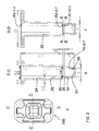
- FIG. 1 shows one example of a cuvette 100 according to the invention.
- FIG. 1a shows a top view of the cuvette 100
- FIG. 1b shows a perspective view of the cuvette 100
- FIG. 1c shows a front view of the cuvette 100
- FIG. 1d shows a cross-section of the cuvette 100 through the plane A-A of FIG. 1c
- FIG. 1e shows a cross-section of the cuvette 100 through the plane B-B of FIG. 1c.
- the drawings of FIG. 1 a-e as well as the following figures are not to scale for clarity of illustration.
- the cuvette 100 comprises a body 10 having outer walls 11 and an inner space 12 for receiving liquids.
- the body 10 comprises an upper part 20.
- the upper part 20 comprises an upper open top portion 21 for allowing liquids to be introduced in the cuvette 100, an upper front wall 22, an upper back wall 23, two upper side walls 24, 25, said upper walls 22, 23, 24, 25 forming four upper inner edges 26 and an upper open bottom portion 27 with a first substantially rectangular cross-section in the plane A-A.
- the body 10 further comprises a lower measurement chamber 30.
- the lower measurement chamber 30 comprises a lower closed bottom portion 31, a lower front wall 32, a lower back wall 33, two lower side walls 34, 35, said lower walls 32, 33, 34, 35 forming four lower inner edges 36 and a lower open top portion 37 with a second substantially rectangular cross-section in a plane B-B smaller than the first substantially rectangular cross-section in the plane A-A.
- the lower front wall 32 and the lower back wall 33 are substantially planar and parallel to each other.
- the body 10 further comprises a transition zone 40 between the plane A-A and the plane B-B, i.e. between the upper part 20 and the lower measurement chamber 30.
- the transition zone 40 comprises four transition inner edges 46 connecting the four lower inner edges 36 to the four upper inner edges 26.
- the lower inner edges 36 comprise fillets having a first radius R1.
- the upper inner edges 26 comprise fillets having a second radius R2, the second radius R2 being larger than the first radius R1.
- the transition inner edges 46 comprise fillets having a gradually increasing radius passing from the first radius R1 in the plane B-B to the second radius R2 in the plane A-A.
- the cuvette 100 has also a third substantially rectangular cross-section in the plane of the upper open top portion 21, which is larger than the first substantially rectangular cross-section in the plane A-A.
- the upper part 20 has a tapered shape with a cross-section, which is gradually increasing from the plane A-A to the top open portion 21 and the upper inner edges 26 comprise fillets having a second radius R2, which is gradually increasing from the plane A-A to the open top portion 21.
- the cuvette 100 further comprises in proximity of the upper open top portion 21 a lip 28 projecting outwards of the cuvette body 10 as a frame. This lip 28 is convenient for handling and holding the cuvette 100 in an analytical instrument.
- the lower front wall 32 and the lower back wall 33 are optically transparent.
- FIG. 2 provides some of the dimensions (in millimeters) for the cuvette of FIG. 1 .
- FIG. 2a s hows the same top view of the cuvette 100 of FIG. 1a.
- FIG. 2a shows a cross-section of the cuvette 100 through a vertical plane C-C passing from the upper top open portion 21 to the lower closed bottom portion 31 through the middle of the body 10.
- FIG. 2b shows a cross-section of the cuvette 100 through a vertical plane D-D passing from the upper top open portion 21 to the lower closed bottom portion 31 through the middle of the body 10 and orthogonal to plane C-C.
- the thickness of the walls of the cuvette body 10 is substantially constant and about 0.5 mm.
- the cuvette 100 has a first substantially squared cross-section in the plane A-A with a width of about 3.8 mm, a second substantially squared cross-section in the plane B-B with a width of about 3 mm, and a third substantially squared cross-section in the plane of the upper open top portion 21 lower closed bottom portion with a width of about 4.2 mm.
- the distance from the plane A-A to the upper top open portion is about 14.7 mm.
- the distance from the lower closed bottom portion 31 to the plane B-B is about 3 mm.
- the distance between the plane A-A and the plane B-B is about 0.6 mm.
- the lower inner edges 36 have fillets with a first radius R1 of about 0.1 mm from the plane B-B to the lower closed bottom portion 31.
- the upper inner edges 26 have fillets with a second radius R2, which is gradually increasing from the plane A-A to the open top portion 21.
- the second radius R2 is about 0.7 mm in the plane A-A and about 1.4 mm in the plane of the upper open top portion 21.
- the transition inner edges 46 connecting the four lower inner edges 36 to the four upper inner edges 26 have fillets with a radius, which is gradually increasing from the plane B-B to the plane A-A passing from 0.1 mm to 0.7 mm within a short distance of 0.6 mm between the plane B-B and the plane A-A.
- This is an example of an abrupt transition, i.e. of a strong change in radius in a short distance, responsible for a strong surface energy, i.e. strong energy barrier, at the lower inner edges in the plane B-B.
- a transition may be considered to be abrupt if the transition inner edges 46 connecting the four lower inner edges 36 to the upper part 20 have fillets with a radius, which is gradually increasing from the plane B-B to the plane A-A passing from a first radius R1, which is smaller than 1 mm to a second radius R2 of several mm, e.g. up to the radius of the cross-section 27 in case of annular, e.g. circular, cross-section 27, within a distance greater than zero and up to 5 mm between the plane B-B and the plane A-A.
- the lower front wall 32 and lower back wall 33 have a substantially rectangular area and comprise corners 39 with a curved shape in proximity of the lower closed bottom portion 31, having a radius R3 of about 0.7 mm.
- the volume of the lower measurement chamber 30 is about 25 ⁇ L.
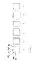
- FIG. 3 shows schematically variants of the cuvette 100 with reference to the geometries of the cross-sections A-A and B-B.
- FIG. 3a shows the embodiment of FIG. 1 and FIG. 2 for comparison.
- FIG. 3b shows an alternative embodiment wherein the lower inner edges 36 are sharp, although more difficult to produce.
- FIG. 3c the cross-section of the plane A-A is larger than the cross-section of the plane B-B only between the edges.
- FIG. 3d shows cross-sections of elongated rectangular shape.
- the cross-section in the plane A-A is substantially circular while the cross-section in the plane B-B is substantially squared.
- FIG. 3e shows schematically variants of the cuvette 100 with reference to the geometries of the cross-sections A-A and B-B.
- cross-section of the plane A-A is larger than the cross-section of the plane B-B only between two opposite edges.
- cross-sections in the plane A-A and B-B may be non-concentric and/or non-symmetric.
- the edges may have fillets with rounded circular or elliptical radius. All these variants may in turn be combined with different geometries of the cross-section in the plane of the top open portion 21, which may be substantially rectangular or annular (not shown).
- FIG. 4 shows schematically the effect of the geometry of the cuvette 100 of FIG. 1 on the liquid meniscus 37.
- a volume of liquid which is smaller than the inner volume of the chamber 30, the liquid will rise quickly along the lower inner edges 26 due the small radius R1 and will stop at the intersection with plane B-B.
- the minimum 38 of the meniscus 37 will rise approaching more and more the plane B-B while the edge of the meniscus 37 will remain confined in the plane B-B rather than continuing to rise along the transition inner edges 46.
- the cuvette 100 is designed so that when a predefined-volume of liquid, e.g.
- FIG. 5 shows the relationship between tolerance measurement window 50 and measurement volume for the cuvette 100 of FIG. 1 .
- the measurement volume is given by the area 51 scanned by the light beam 60 at the intersection between the light beam 60 and the lower front wall 32 times the optical path 61, which is the distance between the lower front wall 32 and lower back wall 33, i.e. 3 mm in this example.
- the tolerance measurement window 50 This means that the position of the tolerance measurement window 50 may change for each measurement and for each cuvette 100.
- the area 51 scanned by the light beam 60 always falls within the tolerance measurement window 50 in order to have a reliable and reproducible measurement. Having fixed the volume of the liquid and the optical path length 61, it is also important to have the area 51 as large as possible in order to obtain a larger measurement signal and thus higher sensitivity.
- the design of the cuvette 100 contributes to raising the minimum 38 of the meniscus 37. By having lower inner edges 36, which comprise fillets having a small first radius R1, contributes also to reduce the influence of the fillets on the size of the tolerance window 50. This enables to increase the area 51 scanned by the light beam 60 while still making sure that the area 51 falls within the tolerance measurement window 50.
- Another improvement is obtained by designing the lower front wall 32 and lower back wall 33 such that they have corners 39 in proximity of the lower closed bottom portion 31 with a shape, which substantially matches the shape of one sector of the light beam 60, e.g. by having the radius R3 of said corners 39 substantially matching the radius R3' of the light beam 60, in this case about 0.7 mm.
- Optimum results are achieved by designing the lower front wall 32 and lower back wall 33 such that they have an area, which is between 2 and 10 times larger than the area 62 of intersection between the lower front wall 32 and the light beam 60.
- the lower front wall 32 and lower back wall 33 are designed such that they have an area, which is between 5 and 6 times larger than the area 62 of intersection between the lower front wall 32 and the light beam 60.
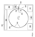
- FIG. 6 depicts schematically an analytical instrument 300 comprising an optical system 200 for photometric measurement of liquids.
- the optical system 200 comprises a light source 203 providing a light beam 60, an optical detector 204, a cuvette holding unit 201 arranged as a rotor comprising an array of cuvette holding positions 202 and a control unit 205 being set up to bring one cuvette 100 at a time in optical alignment with the light source 203 and the optical detector 204 so that the lower front wall 32 faces the light source 203 and the lower back wall 33 faces the optical detector 204.
- the rotor 201 is arranged to rotate and to move a cuvette 100 along an axis parallel to the lower front wall 32 while performing a photometric measurement.
- the instrument 300 further comprises a sample receiving unit 301 for receiving sample tubes (not shown) comprising samples to be assayed.
- the analytical instrument 300 further comprises a reagent holding unit 302 for holding reagent containers (not shown) comprising reagents to perform the assays.
- the instrument 300 further comprises a cuvette feeding unit 303 for feeding optical cuvettes 100 to the cuvette holding unit 201.
- the analytical instrument 300 further comprises a liquid processing unit 304, such as at least one pipetting unit, to deliver samples and/or reagents to cuvettes 100.
- Cuvettes 100 may be temporarily removed from the rotor 201 for addition of samples and/or reagents or for mixing operations by a mixing unit 305.
Landscapes
- Physics & Mathematics (AREA)
- Health & Medical Sciences (AREA)
- Life Sciences & Earth Sciences (AREA)
- Chemical & Material Sciences (AREA)
- Analytical Chemistry (AREA)
- Biochemistry (AREA)
- General Health & Medical Sciences (AREA)
- General Physics & Mathematics (AREA)
- Immunology (AREA)
- Pathology (AREA)
- Optical Measuring Cells (AREA)
- Automatic Analysis And Handling Materials Therefor (AREA)
Priority Applications (1)
| Application Number | Priority Date | Filing Date | Title |
|---|---|---|---|
| EP11192461.9A EP2466291B1 (en) | 2010-12-15 | 2011-12-07 | Cuvette for photometric measurement of small liquid volumes |
Applications Claiming Priority (2)
| Application Number | Priority Date | Filing Date | Title |
|---|---|---|---|
| EP10195225 | 2010-12-15 | ||
| EP11192461.9A EP2466291B1 (en) | 2010-12-15 | 2011-12-07 | Cuvette for photometric measurement of small liquid volumes |
Publications (2)
| Publication Number | Publication Date |
|---|---|
| EP2466291A1 EP2466291A1 (en) | 2012-06-20 |
| EP2466291B1 true EP2466291B1 (en) | 2013-09-11 |
Family
ID=43928125
Family Applications (1)
| Application Number | Title | Priority Date | Filing Date |
|---|---|---|---|
| EP11192461.9A Active EP2466291B1 (en) | 2010-12-15 | 2011-12-07 | Cuvette for photometric measurement of small liquid volumes |
Country Status (3)
| Country | Link |
|---|---|
| US (1) | US9612192B2 (enExample) |
| EP (1) | EP2466291B1 (enExample) |
| JP (1) | JP5746607B2 (enExample) |
Cited By (2)
| Publication number | Priority date | Publication date | Assignee | Title |
|---|---|---|---|---|
| RU2657020C1 (ru) * | 2014-09-29 | 2018-06-08 | БД КИЕСТРА Би.Ви. | Устройство и кюветы для оптического контроля небольших объемов жидкого образца |
| RU2772562C1 (ru) * | 2018-09-27 | 2022-05-23 | Хитачи Хай-Тек Корпорейшн | Реакционный сосуд для автоматического анализатора |
Families Citing this family (32)
| Publication number | Priority date | Publication date | Assignee | Title |
|---|---|---|---|---|
| USD711550S1 (en) | 2012-04-20 | 2014-08-19 | Martin Trump | Container for diagnostic products |
| USD687566S1 (en) * | 2012-04-20 | 2013-08-06 | Stratec Biomedical Ag | Cuvette |
| USD711549S1 (en) | 2012-04-20 | 2014-08-19 | Martin Trump | Container for diagnostic products |
| USD726907S1 (en) | 2012-04-20 | 2015-04-14 | Stratec Biomedical Ag | Needle tip |
| USD688385S1 (en) * | 2012-04-20 | 2013-08-20 | Stratec Biomedical Ag | Cuvette |
| USD687964S1 (en) * | 2012-04-20 | 2013-08-13 | Stratec Biomedical Ag | Cuvette |
| USD687965S1 (en) * | 2012-04-20 | 2013-08-13 | Stratec Biomedical Ag | Cuvette |
| JP6149358B2 (ja) * | 2012-07-31 | 2017-06-21 | ウシオ電機株式会社 | 蛍光測定方法及び蛍光測定キット |
| EP2698624A1 (de) * | 2012-08-16 | 2014-02-19 | Siemens Healthcare Diagnostics Products GmbH | Reaktionsgefäß |
| WO2014031576A1 (en) | 2012-08-20 | 2014-02-27 | Siemens Healthcare Diagnostics Inc. | Methods and apparatus for ascertaining specimen and/or sample container characteristics while in transit |
| US8970837B2 (en) | 2013-03-14 | 2015-03-03 | Laxco Inc. | Apparatus for taking an accurate photometric measurement of a liquid |
| US9359632B2 (en) | 2013-03-15 | 2016-06-07 | Theranos, Inc. | Devices, systems and methods for sample preparation |
| AU2014237362A1 (en) | 2013-03-15 | 2015-09-17 | Theranos Ip Company, Llc | Devices, systems and methods for sample preparation |
| USD743045S1 (en) | 2013-06-21 | 2015-11-10 | Stratec Biomedical Ag | Cuvette |
| JP6208596B2 (ja) * | 2014-02-21 | 2017-10-04 | 株式会社日立ハイテクノロジーズ | 反応セル、及び生化学自動分析装置 |
| EP3026425B1 (en) * | 2014-11-27 | 2020-05-06 | Hach Lange GmbH | Nephelometric turbidimeter vial arrangement |
| WO2016088108A1 (en) * | 2014-12-05 | 2016-06-09 | Bacterioscan Ltd. | Multi-sample laser-scatter measurement instrument with incubation feature, and systems for using the same |
| CN107209115A (zh) | 2015-01-26 | 2017-09-26 | 百克特瑞欧扫描有限责任公司 | 具有转盘式流体样品装置的激光散射测量仪器 |
| EP3088904A1 (de) * | 2015-04-27 | 2016-11-02 | Siemens Healthcare Diagnostics Products GmbH | Verfahren zur überprüfung der funktionsfähigkeit einer waschstation für pipettiernadeln |
| USD810959S1 (en) | 2015-09-29 | 2018-02-20 | Bd Kiestra B.V. | Cuvette tray |
| USD808036S1 (en) | 2015-09-29 | 2018-01-16 | Bd Kiestra B.V. | Cuvette |
| JP2018009968A (ja) * | 2016-06-30 | 2018-01-18 | 株式会社Screenホールディングス | ウェルプレート及びその使用方法 |
| WO2018017472A1 (en) * | 2016-07-18 | 2018-01-25 | Siemens Healthcare Diagnostics Inc. | Sample analyzer system with a sample vessel having opaque and translucent portions |
| JP6735179B2 (ja) * | 2016-08-10 | 2020-08-05 | 浜松ホトニクス株式会社 | 測定容器 |
| WO2018150944A1 (ja) * | 2017-02-15 | 2018-08-23 | コニカミノルタ株式会社 | 検査チップ及び検査システム |
| USD901036S1 (en) * | 2019-03-25 | 2020-11-03 | Avails Medical, Inc. | Cuvette |
| LU101174B1 (en) | 2019-04-12 | 2020-10-12 | Stratec Se | Sample cuvette |
| CN113099104B (zh) * | 2020-01-09 | 2023-06-27 | 博泰车联网科技(上海)股份有限公司 | 用于采集图像的方法、电子设备、计算机存储介质和车辆 |
| US20230306614A1 (en) * | 2022-03-28 | 2023-09-28 | Darvis Inc. | System and method for tracking surgical kit |
| USD1014780S1 (en) | 2022-04-15 | 2024-02-13 | Instrumentation Laboratory Co. | Cuvette |
| EP4261526A1 (en) * | 2022-04-15 | 2023-10-18 | Instrumentation Laboratory Company | A fluid testing system |
| CN119780010B (zh) * | 2025-01-06 | 2025-08-29 | 华高(山东)生物科技有限公司 | 一种饲料酶制剂活性检测仪器 |
Family Cites Families (11)
| Publication number | Priority date | Publication date | Assignee | Title |
|---|---|---|---|---|
| DE3246592C1 (de) | 1982-12-16 | 1983-10-27 | Eppendorf Gerätebau Netheler + Hinz GmbH, 2000 Hamburg | Kuevette zur Mischung und fuer optische Untersuchungen |
| JPH01144846U (enExample) * | 1988-03-30 | 1989-10-04 | ||
| US5571479A (en) | 1994-02-18 | 1996-11-05 | Hoffmann-La Roche Inc. | Cuvette |
| DE19826470C2 (de) | 1998-06-13 | 2001-10-18 | Eppendorf Ag | Küvettensystem und Küvette |
| JP3787302B2 (ja) * | 2001-12-13 | 2006-06-21 | 富士写真フイルム株式会社 | 測定チップ |
| US7138091B2 (en) * | 2003-07-18 | 2006-11-21 | Dade Behring Inc. | Reaction cuvette having anti-wicking features for use in an automatic clinical analyzer |
| WO2006134777A1 (ja) * | 2005-06-17 | 2006-12-21 | Olympus Corporation | 攪拌容器及び分析装置 |
| EP1909094B1 (en) * | 2005-07-27 | 2017-05-03 | Sysmex Corporation | Cuvette |
| US8703072B2 (en) * | 2008-09-12 | 2014-04-22 | Oliver Egeler | Cell culture vessels for meniscus reduction with aqueous solutions |
| JP2010085281A (ja) * | 2008-09-30 | 2010-04-15 | Fujifilm Corp | 容器 |
| US8493559B2 (en) * | 2009-03-17 | 2013-07-23 | Trevor Harvard | Cuvette |
-
2011
- 2011-12-07 EP EP11192461.9A patent/EP2466291B1/en active Active
- 2011-12-14 JP JP2011273564A patent/JP5746607B2/ja active Active
- 2011-12-14 US US13/325,631 patent/US9612192B2/en active Active
Cited By (3)
| Publication number | Priority date | Publication date | Assignee | Title |
|---|---|---|---|---|
| RU2657020C1 (ru) * | 2014-09-29 | 2018-06-08 | БД КИЕСТРА Би.Ви. | Устройство и кюветы для оптического контроля небольших объемов жидкого образца |
| US10935490B2 (en) * | 2014-09-29 | 2021-03-02 | Bd Kiestra B.V. | Apparatus for optical inspection of small volumes of liquid sample and cuvettes therefor |
| RU2772562C1 (ru) * | 2018-09-27 | 2022-05-23 | Хитачи Хай-Тек Корпорейшн | Реакционный сосуд для автоматического анализатора |
Also Published As
| Publication number | Publication date |
|---|---|
| JP5746607B2 (ja) | 2015-07-08 |
| EP2466291A1 (en) | 2012-06-20 |
| US20120156796A1 (en) | 2012-06-21 |
| JP2012127964A (ja) | 2012-07-05 |
| US9612192B2 (en) | 2017-04-04 |
Similar Documents
| Publication | Publication Date | Title |
|---|---|---|
| EP2466291B1 (en) | Cuvette for photometric measurement of small liquid volumes | |
| ES2271941T3 (es) | Metodo de analisis automatico con acceso continuo y aleatorio. | |
| JP4119845B2 (ja) | 積み重ね可能なアリクォット容器アレイ | |
| KR101260400B1 (ko) | 생체샘플의 복합자동분석장치, 자동분석방법 및 반응 큐벳 | |
| EP2860528B1 (en) | Automatic analysis apparatus | |
| ES2261529T3 (es) | Dispositivo y metodo de deteccion de nivel de liquido. | |
| JP6581483B2 (ja) | 検体分析装置 | |
| JP7414911B2 (ja) | 自動分析装置 | |
| US20180267069A1 (en) | Sample analyzer | |
| EP2128627B1 (en) | Analyzer for performing medical diagnostic analysis | |
| EP2466292B1 (en) | System for performing scattering and absorbance assays | |
| EP3508858B1 (en) | Sample measurement method and sample measurement device | |
| US9606136B2 (en) | Device and method for transferring reaction vessels | |
| EP2746774A1 (en) | System and method for testing liquid samples | |
| US20130234053A1 (en) | Diagnostic instrument and flow process | |
| JP6634222B2 (ja) | 体外診断分析方法およびシステム | |
| EP2607883A1 (en) | System for photometric measurement of liquids | |
| US20060292038A1 (en) | Automated sample analyzer and cuvette | |
| CN110967518B (zh) | 样本测定装置和在样本测定装置中执行的方法 | |
| JP7300826B2 (ja) | 分析装置及び分析方法 | |
| Boyd et al. | Automation in the clinical laboratory | |
| JPS61262639A (ja) | 自動分析装置 | |
| RU2772562C1 (ru) | Реакционный сосуд для автоматического анализатора | |
| WO2025115320A1 (ja) | 発光分析用検出装置及び自動分析装置 | |
| JPS61164162A (ja) | 検体分析法 |
Legal Events
| Date | Code | Title | Description |
|---|---|---|---|
| PUAI | Public reference made under article 153(3) epc to a published international application that has entered the european phase |
Free format text: ORIGINAL CODE: 0009012 |
|
| AK | Designated contracting states |
Kind code of ref document: A1 Designated state(s): AL AT BE BG CH CY CZ DE DK EE ES FI FR GB GR HR HU IE IS IT LI LT LU LV MC MK MT NL NO PL PT RO RS SE SI SK SM TR |
|
| AX | Request for extension of the european patent |
Extension state: BA ME |
|
| 17P | Request for examination filed |
Effective date: 20121220 |
|
| GRAP | Despatch of communication of intention to grant a patent |
Free format text: ORIGINAL CODE: EPIDOSNIGR1 |
|
| INTG | Intention to grant announced |
Effective date: 20130412 |
|
| GRAS | Grant fee paid |
Free format text: ORIGINAL CODE: EPIDOSNIGR3 |
|
| GRAA | (expected) grant |
Free format text: ORIGINAL CODE: 0009210 |
|
| AK | Designated contracting states |
Kind code of ref document: B1 Designated state(s): AL AT BE BG CH CY CZ DE DK EE ES FI FR GB GR HR HU IE IS IT LI LT LU LV MC MK MT NL NO PL PT RO RS SE SI SK SM TR |
|
| REG | Reference to a national code |
Ref country code: GB Ref legal event code: FG4D |
|
| REG | Reference to a national code |
Ref country code: CH Ref legal event code: EP |
|
| REG | Reference to a national code |
Ref country code: AT Ref legal event code: REF Ref document number: 631902 Country of ref document: AT Kind code of ref document: T Effective date: 20130915 |
|
| REG | Reference to a national code |
Ref country code: IE Ref legal event code: FG4D |
|
| REG | Reference to a national code |
Ref country code: DE Ref legal event code: R096 Ref document number: 602011003024 Country of ref document: DE Effective date: 20131114 |
|
| PG25 | Lapsed in a contracting state [announced via postgrant information from national office to epo] |
Ref country code: HR Free format text: LAPSE BECAUSE OF FAILURE TO SUBMIT A TRANSLATION OF THE DESCRIPTION OR TO PAY THE FEE WITHIN THE PRESCRIBED TIME-LIMIT Effective date: 20130911 Ref country code: SE Free format text: LAPSE BECAUSE OF FAILURE TO SUBMIT A TRANSLATION OF THE DESCRIPTION OR TO PAY THE FEE WITHIN THE PRESCRIBED TIME-LIMIT Effective date: 20130911 Ref country code: CY Free format text: LAPSE BECAUSE OF FAILURE TO SUBMIT A TRANSLATION OF THE DESCRIPTION OR TO PAY THE FEE WITHIN THE PRESCRIBED TIME-LIMIT Effective date: 20130828 Ref country code: LT Free format text: LAPSE BECAUSE OF FAILURE TO SUBMIT A TRANSLATION OF THE DESCRIPTION OR TO PAY THE FEE WITHIN THE PRESCRIBED TIME-LIMIT Effective date: 20130911 Ref country code: NO Free format text: LAPSE BECAUSE OF FAILURE TO SUBMIT A TRANSLATION OF THE DESCRIPTION OR TO PAY THE FEE WITHIN THE PRESCRIBED TIME-LIMIT Effective date: 20131211 |
|
| REG | Reference to a national code |
Ref country code: NL Ref legal event code: VDEP Effective date: 20130911 |
|
| REG | Reference to a national code |
Ref country code: AT Ref legal event code: MK05 Ref document number: 631902 Country of ref document: AT Kind code of ref document: T Effective date: 20130911 |
|
| REG | Reference to a national code |
Ref country code: LT Ref legal event code: MG4D |
|
| PG25 | Lapsed in a contracting state [announced via postgrant information from national office to epo] |
Ref country code: LV Free format text: LAPSE BECAUSE OF FAILURE TO SUBMIT A TRANSLATION OF THE DESCRIPTION OR TO PAY THE FEE WITHIN THE PRESCRIBED TIME-LIMIT Effective date: 20130911 Ref country code: SI Free format text: LAPSE BECAUSE OF FAILURE TO SUBMIT A TRANSLATION OF THE DESCRIPTION OR TO PAY THE FEE WITHIN THE PRESCRIBED TIME-LIMIT Effective date: 20130911 Ref country code: GR Free format text: LAPSE BECAUSE OF FAILURE TO SUBMIT A TRANSLATION OF THE DESCRIPTION OR TO PAY THE FEE WITHIN THE PRESCRIBED TIME-LIMIT Effective date: 20131212 Ref country code: FI Free format text: LAPSE BECAUSE OF FAILURE TO SUBMIT A TRANSLATION OF THE DESCRIPTION OR TO PAY THE FEE WITHIN THE PRESCRIBED TIME-LIMIT Effective date: 20130911 |
|
| PG25 | Lapsed in a contracting state [announced via postgrant information from national office to epo] |
Ref country code: BE Free format text: LAPSE BECAUSE OF FAILURE TO SUBMIT A TRANSLATION OF THE DESCRIPTION OR TO PAY THE FEE WITHIN THE PRESCRIBED TIME-LIMIT Effective date: 20130911 Ref country code: CY Free format text: LAPSE BECAUSE OF FAILURE TO SUBMIT A TRANSLATION OF THE DESCRIPTION OR TO PAY THE FEE WITHIN THE PRESCRIBED TIME-LIMIT Effective date: 20130911 |
|
| PG25 | Lapsed in a contracting state [announced via postgrant information from national office to epo] |
Ref country code: IS Free format text: LAPSE BECAUSE OF FAILURE TO SUBMIT A TRANSLATION OF THE DESCRIPTION OR TO PAY THE FEE WITHIN THE PRESCRIBED TIME-LIMIT Effective date: 20140111 Ref country code: NL Free format text: LAPSE BECAUSE OF FAILURE TO SUBMIT A TRANSLATION OF THE DESCRIPTION OR TO PAY THE FEE WITHIN THE PRESCRIBED TIME-LIMIT Effective date: 20130911 Ref country code: EE Free format text: LAPSE BECAUSE OF FAILURE TO SUBMIT A TRANSLATION OF THE DESCRIPTION OR TO PAY THE FEE WITHIN THE PRESCRIBED TIME-LIMIT Effective date: 20130911 Ref country code: SK Free format text: LAPSE BECAUSE OF FAILURE TO SUBMIT A TRANSLATION OF THE DESCRIPTION OR TO PAY THE FEE WITHIN THE PRESCRIBED TIME-LIMIT Effective date: 20130911 Ref country code: CZ Free format text: LAPSE BECAUSE OF FAILURE TO SUBMIT A TRANSLATION OF THE DESCRIPTION OR TO PAY THE FEE WITHIN THE PRESCRIBED TIME-LIMIT Effective date: 20130911 Ref country code: RO Free format text: LAPSE BECAUSE OF FAILURE TO SUBMIT A TRANSLATION OF THE DESCRIPTION OR TO PAY THE FEE WITHIN THE PRESCRIBED TIME-LIMIT Effective date: 20130911 |
|
| PG25 | Lapsed in a contracting state [announced via postgrant information from national office to epo] |
Ref country code: PL Free format text: LAPSE BECAUSE OF FAILURE TO SUBMIT A TRANSLATION OF THE DESCRIPTION OR TO PAY THE FEE WITHIN THE PRESCRIBED TIME-LIMIT Effective date: 20130911 Ref country code: ES Free format text: LAPSE BECAUSE OF FAILURE TO SUBMIT A TRANSLATION OF THE DESCRIPTION OR TO PAY THE FEE WITHIN THE PRESCRIBED TIME-LIMIT Effective date: 20130911 Ref country code: AT Free format text: LAPSE BECAUSE OF FAILURE TO SUBMIT A TRANSLATION OF THE DESCRIPTION OR TO PAY THE FEE WITHIN THE PRESCRIBED TIME-LIMIT Effective date: 20130911 |
|
| REG | Reference to a national code |
Ref country code: DE Ref legal event code: R097 Ref document number: 602011003024 Country of ref document: DE |
|
| PG25 | Lapsed in a contracting state [announced via postgrant information from national office to epo] |
Ref country code: PT Free format text: LAPSE BECAUSE OF FAILURE TO SUBMIT A TRANSLATION OF THE DESCRIPTION OR TO PAY THE FEE WITHIN THE PRESCRIBED TIME-LIMIT Effective date: 20140113 |
|
| PLBE | No opposition filed within time limit |
Free format text: ORIGINAL CODE: 0009261 |
|
| STAA | Information on the status of an ep patent application or granted ep patent |
Free format text: STATUS: NO OPPOSITION FILED WITHIN TIME LIMIT |
|
| 26N | No opposition filed |
Effective date: 20140612 |
|
| PG25 | Lapsed in a contracting state [announced via postgrant information from national office to epo] |
Ref country code: IT Free format text: LAPSE BECAUSE OF FAILURE TO SUBMIT A TRANSLATION OF THE DESCRIPTION OR TO PAY THE FEE WITHIN THE PRESCRIBED TIME-LIMIT Effective date: 20130911 Ref country code: LU Free format text: LAPSE BECAUSE OF FAILURE TO SUBMIT A TRANSLATION OF THE DESCRIPTION OR TO PAY THE FEE WITHIN THE PRESCRIBED TIME-LIMIT Effective date: 20131207 |
|
| REG | Reference to a national code |
Ref country code: IE Ref legal event code: MM4A |
|
| REG | Reference to a national code |
Ref country code: DE Ref legal event code: R097 Ref document number: 602011003024 Country of ref document: DE Effective date: 20140612 |
|
| PG25 | Lapsed in a contracting state [announced via postgrant information from national office to epo] |
Ref country code: DK Free format text: LAPSE BECAUSE OF FAILURE TO SUBMIT A TRANSLATION OF THE DESCRIPTION OR TO PAY THE FEE WITHIN THE PRESCRIBED TIME-LIMIT Effective date: 20130911 |
|
| PG25 | Lapsed in a contracting state [announced via postgrant information from national office to epo] |
Ref country code: IE Free format text: LAPSE BECAUSE OF NON-PAYMENT OF DUE FEES Effective date: 20131207 |
|
| PG25 | Lapsed in a contracting state [announced via postgrant information from national office to epo] |
Ref country code: MC Free format text: LAPSE BECAUSE OF FAILURE TO SUBMIT A TRANSLATION OF THE DESCRIPTION OR TO PAY THE FEE WITHIN THE PRESCRIBED TIME-LIMIT Effective date: 20130911 |
|
| PG25 | Lapsed in a contracting state [announced via postgrant information from national office to epo] |
Ref country code: SM Free format text: LAPSE BECAUSE OF FAILURE TO SUBMIT A TRANSLATION OF THE DESCRIPTION OR TO PAY THE FEE WITHIN THE PRESCRIBED TIME-LIMIT Effective date: 20130911 Ref country code: TR Free format text: LAPSE BECAUSE OF FAILURE TO SUBMIT A TRANSLATION OF THE DESCRIPTION OR TO PAY THE FEE WITHIN THE PRESCRIBED TIME-LIMIT Effective date: 20130911 |
|
| PG25 | Lapsed in a contracting state [announced via postgrant information from national office to epo] |
Ref country code: MK Free format text: LAPSE BECAUSE OF FAILURE TO SUBMIT A TRANSLATION OF THE DESCRIPTION OR TO PAY THE FEE WITHIN THE PRESCRIBED TIME-LIMIT Effective date: 20130911 Ref country code: BG Free format text: LAPSE BECAUSE OF FAILURE TO SUBMIT A TRANSLATION OF THE DESCRIPTION OR TO PAY THE FEE WITHIN THE PRESCRIBED TIME-LIMIT Effective date: 20130911 Ref country code: HU Free format text: LAPSE BECAUSE OF FAILURE TO SUBMIT A TRANSLATION OF THE DESCRIPTION OR TO PAY THE FEE WITHIN THE PRESCRIBED TIME-LIMIT; INVALID AB INITIO Effective date: 20111207 Ref country code: RS Free format text: LAPSE BECAUSE OF FAILURE TO SUBMIT A TRANSLATION OF THE DESCRIPTION OR TO PAY THE FEE WITHIN THE PRESCRIBED TIME-LIMIT Effective date: 20131211 |
|
| PG25 | Lapsed in a contracting state [announced via postgrant information from national office to epo] |
Ref country code: MT Free format text: LAPSE BECAUSE OF FAILURE TO SUBMIT A TRANSLATION OF THE DESCRIPTION OR TO PAY THE FEE WITHIN THE PRESCRIBED TIME-LIMIT Effective date: 20130911 |
|
| REG | Reference to a national code |
Ref country code: FR Ref legal event code: PLFP Year of fee payment: 5 |
|
| REG | Reference to a national code |
Ref country code: FR Ref legal event code: PLFP Year of fee payment: 6 |
|
| REG | Reference to a national code |
Ref country code: FR Ref legal event code: PLFP Year of fee payment: 7 |
|
| PGFP | Annual fee paid to national office [announced via postgrant information from national office to epo] |
Ref country code: CH Payment date: 20171025 Year of fee payment: 7 |
|
| PG25 | Lapsed in a contracting state [announced via postgrant information from national office to epo] |
Ref country code: AL Free format text: LAPSE BECAUSE OF FAILURE TO SUBMIT A TRANSLATION OF THE DESCRIPTION OR TO PAY THE FEE WITHIN THE PRESCRIBED TIME-LIMIT Effective date: 20130911 |
|
| REG | Reference to a national code |
Ref country code: CH Ref legal event code: PL |
|
| PG25 | Lapsed in a contracting state [announced via postgrant information from national office to epo] |
Ref country code: CH Free format text: LAPSE BECAUSE OF NON-PAYMENT OF DUE FEES Effective date: 20181231 Ref country code: LI Free format text: LAPSE BECAUSE OF NON-PAYMENT OF DUE FEES Effective date: 20181231 |
|
| PGFP | Annual fee paid to national office [announced via postgrant information from national office to epo] |
Ref country code: GB Payment date: 20231124 Year of fee payment: 13 |
|
| PGFP | Annual fee paid to national office [announced via postgrant information from national office to epo] |
Ref country code: DE Payment date: 20241121 Year of fee payment: 14 |
|
| PGFP | Annual fee paid to national office [announced via postgrant information from national office to epo] |
Ref country code: FR Payment date: 20241121 Year of fee payment: 14 |
|
| GBPC | Gb: european patent ceased through non-payment of renewal fee |
Effective date: 20241207 |
|
| PG25 | Lapsed in a contracting state [announced via postgrant information from national office to epo] |
Ref country code: GB Free format text: LAPSE BECAUSE OF NON-PAYMENT OF DUE FEES Effective date: 20241207 |