EP2466089A2 - Refroidisseur d'air de suralimentation - Google Patents
Refroidisseur d'air de suralimentation Download PDFInfo
- Publication number
- EP2466089A2 EP2466089A2 EP11191368A EP11191368A EP2466089A2 EP 2466089 A2 EP2466089 A2 EP 2466089A2 EP 11191368 A EP11191368 A EP 11191368A EP 11191368 A EP11191368 A EP 11191368A EP 2466089 A2 EP2466089 A2 EP 2466089A2
- Authority
- EP
- European Patent Office
- Prior art keywords
- coolant
- charge air
- intercooler
- air cooler
- coolant pump
- Prior art date
- Legal status (The legal status is an assumption and is not a legal conclusion. Google has not performed a legal analysis and makes no representation as to the accuracy of the status listed.)
- Granted
Links
Images
Classifications
-
- F—MECHANICAL ENGINEERING; LIGHTING; HEATING; WEAPONS; BLASTING
- F02—COMBUSTION ENGINES; HOT-GAS OR COMBUSTION-PRODUCT ENGINE PLANTS
- F02B—INTERNAL-COMBUSTION PISTON ENGINES; COMBUSTION ENGINES IN GENERAL
- F02B29/00—Engines characterised by provision for charging or scavenging not provided for in groups F02B25/00, F02B27/00 or F02B33/00 - F02B39/00; Details thereof
- F02B29/04—Cooling of air intake supply
- F02B29/045—Constructional details of the heat exchangers, e.g. pipes, plates, ribs, insulation, materials, or manufacturing and assembly
- F02B29/0462—Liquid cooled heat exchangers
-
- F—MECHANICAL ENGINEERING; LIGHTING; HEATING; WEAPONS; BLASTING
- F02—COMBUSTION ENGINES; HOT-GAS OR COMBUSTION-PRODUCT ENGINE PLANTS
- F02B—INTERNAL-COMBUSTION PISTON ENGINES; COMBUSTION ENGINES IN GENERAL
- F02B29/00—Engines characterised by provision for charging or scavenging not provided for in groups F02B25/00, F02B27/00 or F02B33/00 - F02B39/00; Details thereof
- F02B29/04—Cooling of air intake supply
- F02B29/045—Constructional details of the heat exchangers, e.g. pipes, plates, ribs, insulation, materials, or manufacturing and assembly
- F02B29/0475—Constructional details of the heat exchangers, e.g. pipes, plates, ribs, insulation, materials, or manufacturing and assembly the intake air cooler being combined with another device, e.g. heater, valve, compressor, filter or EGR cooler, or being assembled on a special engine location
-
- Y—GENERAL TAGGING OF NEW TECHNOLOGICAL DEVELOPMENTS; GENERAL TAGGING OF CROSS-SECTIONAL TECHNOLOGIES SPANNING OVER SEVERAL SECTIONS OF THE IPC; TECHNICAL SUBJECTS COVERED BY FORMER USPC CROSS-REFERENCE ART COLLECTIONS [XRACs] AND DIGESTS
- Y02—TECHNOLOGIES OR APPLICATIONS FOR MITIGATION OR ADAPTATION AGAINST CLIMATE CHANGE
- Y02T—CLIMATE CHANGE MITIGATION TECHNOLOGIES RELATED TO TRANSPORTATION
- Y02T10/00—Road transport of goods or passengers
- Y02T10/10—Internal combustion engine [ICE] based vehicles
- Y02T10/12—Improving ICE efficiencies
Definitions
- the present invention relates to a charge air cooler of an internal combustion engine according to the preamble of claim l.
- the invention also relates to an internal combustion engine equipped with such a charge air cooler.
- a generic intercooler which is composed of flat tubes, corrugated fins, collecting tanks and connecting pieces, wherein the individual parts of the charge air cooler made of aluminum and are soldered together.
- a construction principle known from parallel flow condensers was transferred to the intercooler by placing it in a housing through which the charge air can flow.
- a 1 is another intercooler known in the housing charge air flows in and out, thereby flowing through the intercooler.
- the housing has a mounting opening into which the intercooler can be used and secured with its connection plate. This is to be achieved in particular that the intercooler with the housing forms a structural unit that should be more stable against vibration and vibration.
- a disadvantage of the known prior art is that the intercooler each as a separate component in a cooling circuit, such as a Internal combustion engine is installed and can not be operated without a separate pump.
- the present invention is concerned with a problem for an intercooler of the generic type to provide an improved or at least one alternative embodiment, which is characterized in particular by a compact design.
- the invention is based on the general idea, at the same time to integrate a coolant pump for conveying or circulating the coolant in a known indirect intercooler for the intake of an internal combustion engine with connecting pieces for connection to a separate, low-temperature coolant circuit, and thereby a separate assembly the same, combined with an increased space requirement and increased assembly costs to avoid.
- the integration of the coolant pump in the intercooler it is thus possible to achieve an overall much more compact design, which is particularly in view of a steadily shrinking space in modern engine compartments of great advantage.
- the coolant pump can be integrated into the charge air cooler in such a way that it can be removed or exchanged more easily, for example for maintenance purposes.
- the coolant pump is integrated in a coolant collecting container of the charge air cooler.
- the coolant reservoir a Forms coolant sump into which projects the coolant pump, which can be ensured that it promotes only coolant and not air.
- the coolant collecting container is also preferably arranged such that it is easily accessible for maintenance purposes, so that maintenance of the coolant pump is comparatively easily possible.
- the coolant pump can be inserted into a recess arranged on the coolant collecting container, for example screwed or clipped, whereby the assembly of the coolant pump on the coolant collecting container is additionally simplified.
- the recess may be formed, for example, as the entire coolant reservoir made of plastic, in particular as a plastic injection molded part, whereby on the one hand low-cost and on the other hand qualitatively very high-quality production of the coolant reservoir and thus the intercooler is possible.
- the coolant reservoir can be made of other suitable materials such as aluminum.
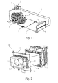
- an inventive indirect charge air cooler 1 of an internal combustion engine 2 is integrated into a low-temperature cooling circuit 3.
- the intercooler 1 serves to cool a compressed charge air flow, which is provided by an exhaust gas turbocharger 4. So far, a coolant pump for conveying the present in the cooling circuit 3 coolant was required in the cooling circuit 3 at any point.
- a coolant pump 5 (see also Figures 2 and 3 ) integrated directly into the intercooler 1. Looking at the FIG. 1 , it can be seen that in principle two different coolant circuits 3 and 3 'are provided, wherein the main coolant circuit 3' is used for cooling the internal combustion engine 2.
- a main cooler 6 is integrated in the coolant circuit 3 ', wherein the coolant in the coolant circuit 3' is circulated by a separate coolant pump 7.
- the two cooling circuits 3 and 3 ' are formed separately from each other, that is, there is no fluidic connection between the two.
- a secondary cooler 8 For cooling the coolant in the low-temperature cooling circuit 3, a secondary cooler 8 is provided, the cooling capacity is usually lower compared to the main cooler 6.
- the coolant pump 5 By integrating the coolant pump 5 in the Intercooler 1, this no longer needs to be placed separately to the intercooler 1 in the course of the coolant circuit 3 elsewhere, which on the one hand, an advantageous package effect is achieved and thus a space requirement can be reduced.
- an assembly effort can be considerably reduced, since the coolant pump 5 can already be installed in advance in the intercooler 1 and integrated together with this in the coolant circuit 3. A separate assembly of the coolant pump 5 elsewhere in the coolant circuit 3 can be omitted.
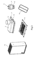
- the coolant pump 5 is integrated in a coolant collecting container 9, also called a water tank for short.
- the coolant collecting container 9 is designed in the manner of a coolant sump, which ensures that the coolant pump 5 is always surrounded by coolant.
- the coolant collecting container 9 is preferably made of plastic, in particular as a plastic injection molded part, and thereby on the one hand inexpensive and on the other hand to produce high quality.
- the coolant receiver can be made of plastic.
- the coolant pump 5 has an electric motor 11 as a drive, on whose rotor an impeller 12 is arranged rotationally fixed.
- the impeller 12 forms, together with an inner wall of the recess 10 of the coolant collecting container 9, the coolant pump 5.
- the coolant collecting container 9 via an adapter plate 13 (see Figures 2 and 3 ), connected to a heat exchanger device 14, wherein the Heat exchanger device 14 in a charge air duct 15 (see. FIG. 2 ) and flows around to be cooled charge air.
- the intercooler 1 consists of many parallel, coolant flowing through flat tubes 20. There are two adjacent rows of coolant tubes.
- the cooler here is flowed through in a U-shape, so there is at the opposite end of the adapter plate 13 an end plate 21 in which the flow of the coolant is deflected. That is, through the one row of coolant tubes 20, the coolant flows downwardly and up through the other row after deflection in the end plate 21.
- the coolant tubes 20 are usually soldered to the adapter plate 13 and the end plate.
- baffles 22 which are arranged around the coolant tubes 20 around. Between each two coolant tubes 20 are not shown here so-called cut slats arranged in order to optimize the performance of the charge air cooler 1.
- An attachment of the intercooler 1 to the charge air duct 15 takes place via the adapter plate 13, for example by means of a screwing the same on the charge air duct 15.
- the seal 16 is located between the adapter plate 13 and the coolant reservoir 9 and provides a density separation of the coolant flowing into the intercooler 1 and the outflowing coolant.
- the coolant collecting container 9 is fastened to the adapter plate 13 by means of clamping. Also integrated in the coolant collecting container 9 is a connecting piece (inlet) 17 and a drain 18 for the coolant to be delivered.
- the position of the coolant pump 5 can both in the Fig. 3 shown on the downstream side, as well as be provided on the inflow side in the coolant receiver 9.
- the charge air cooler 1 With the charge air cooler 1 according to the invention, it is thus possible to integrate this space-optimized and at the same time easy to maintain in the coolant circuit 3.
- the coolant pump 5 which is inventively formed by the coolant reservoir 9, whereby a reduction in the variety of parts and a reduction of assembly costs can be achieved.
Landscapes
- Engineering & Computer Science (AREA)
- Physics & Mathematics (AREA)
- Thermal Sciences (AREA)
- Chemical & Material Sciences (AREA)
- Combustion & Propulsion (AREA)
- Mechanical Engineering (AREA)
- General Engineering & Computer Science (AREA)
- Cooling Or The Like Of Electrical Apparatus (AREA)
- Supercharger (AREA)
- Structures Of Non-Positive Displacement Pumps (AREA)
- Applications Or Details Of Rotary Compressors (AREA)
- Heat-Exchange Devices With Radiators And Conduit Assemblies (AREA)
Applications Claiming Priority (1)
| Application Number | Priority Date | Filing Date | Title |
|---|---|---|---|
| DE102010063265A DE102010063265A1 (de) | 2010-12-16 | 2010-12-16 | Ladeluftkühler |
Publications (3)
| Publication Number | Publication Date |
|---|---|
| EP2466089A2 true EP2466089A2 (fr) | 2012-06-20 |
| EP2466089A3 EP2466089A3 (fr) | 2014-01-01 |
| EP2466089B1 EP2466089B1 (fr) | 2017-01-11 |
Family
ID=45217324
Family Applications (1)
| Application Number | Title | Priority Date | Filing Date |
|---|---|---|---|
| EP11191368.7A Not-in-force EP2466089B1 (fr) | 2010-12-16 | 2011-11-30 | Refroidisseur d'air de suralimentation |
Country Status (4)
| Country | Link |
|---|---|
| US (1) | US8857415B2 (fr) |
| EP (1) | EP2466089B1 (fr) |
| CN (1) | CN102536425B (fr) |
| DE (1) | DE102010063265A1 (fr) |
Cited By (2)
| Publication number | Priority date | Publication date | Assignee | Title |
|---|---|---|---|---|
| WO2015001107A1 (fr) * | 2013-07-04 | 2015-01-08 | Valeo Systemes Thermiques | Dispositif de regulation de la circulation d'un liquide de refroidissement pour un echangeur de chaleur, en particulier refroidisseur d'air de suralimentation de moteur de vehicule automobile |
| WO2018037171A1 (fr) * | 2016-08-24 | 2018-03-01 | Psa Automobiles Sa | Dispositif de refroidissement de système de suralimentation d'air de moteur thermique, et système de suralimentation d'air equipé d'un tel dispositif |
Families Citing this family (4)
| Publication number | Priority date | Publication date | Assignee | Title |
|---|---|---|---|---|
| FR2975765B1 (fr) | 2011-05-26 | 2016-01-29 | Valeo Systemes Thermiques | Echangeur thermique, notamment pour vehicule automobile, et dispositif d'admission d'air correspondant |
| FR2975768B1 (fr) * | 2011-05-26 | 2016-01-29 | Valeo Systemes Thermiques | Echangeur thermique, notamment pour vehicule automobile, et dispositif d'admission d'air correspondant |
| KR101500383B1 (ko) * | 2013-10-14 | 2015-03-09 | 현대자동차 주식회사 | 자동차의 에어 덕트 및 냉각 장치 |
| DE102015015449A1 (de) * | 2015-12-02 | 2017-06-08 | Mann + Hummel Gmbh | Luftführendes Bauteil, insbesondere Saugrohr, mit darin angeordnetem Ladeluftkühler und Ladeluftkühler |
Citations (4)
| Publication number | Priority date | Publication date | Assignee | Title |
|---|---|---|---|---|
| WO2005001366A2 (fr) | 2003-06-24 | 2005-01-06 | Valeo Thermique Moteur | Echangeur de chaleur comportant un boitier et un faisceau en tole d’aluminium assembles par brasage |
| EP1785609A1 (fr) | 2005-11-11 | 2007-05-16 | Modine Manufacturing Company | Échangeur de chaleur à plaques, en particulier refroidisseur d'air de suralimentation |
| EP1795847A2 (fr) | 2005-12-09 | 2007-06-13 | Modine Manufacturing Company | Echangeur de chaleur, en particulier refroidisseur d'air de suralimentation |
| DE102007043992B4 (de) | 2007-09-14 | 2009-08-27 | Pierburg Gmbh | Ladeluftmodul für eine Verbrennungskraftmaschine |
Family Cites Families (16)
| Publication number | Priority date | Publication date | Assignee | Title |
|---|---|---|---|---|
| GB8313907D0 (en) * | 1983-05-19 | 1983-06-22 | Sabre Engines | Engine cooling system |
| US5385132A (en) * | 1993-12-14 | 1995-01-31 | Caterpillar Inc. | Engine fluid system |
| US6257211B1 (en) * | 2000-07-14 | 2001-07-10 | Florencio Vela, Jr. | Engine cooling device |
| US6546919B2 (en) * | 2001-06-14 | 2003-04-15 | Caterpillar Inc | Combined remote first intake air aftercooler and a second fluid from an engine cooler for an engine |
| DE10254016A1 (de) * | 2002-11-19 | 2004-06-03 | Behr Gmbh & Co. Kg | Vorrichtung zur Kühlung von Ladeluft und Verfahren zum Betreiben einer derartigen Vorrichtung |
| DE10215779B4 (de) * | 2002-04-10 | 2006-01-26 | Robert Bosch Gmbh | Brennkraftmaschine mit einer Aufladevorrichtung |
| US6732680B1 (en) * | 2003-01-31 | 2004-05-11 | Ford Global Technologies, Llc | Internal combustion engine with liquid coolant pump |
| DE10317003A1 (de) * | 2003-04-11 | 2004-12-09 | Behr Gmbh & Co. Kg | Kreislaufanordnung zur Kühlung von Ladeluft und Verfahren zum Betreiben einer derartigen Kreislaufanordnung |
| US6796134B1 (en) * | 2003-08-05 | 2004-09-28 | Daimlerchrysler Corporation | Charge air intercooler having a fluid loop integrated with the vehicle air conditioning system |
| US8037872B2 (en) * | 2007-05-31 | 2011-10-18 | Caterpillar Inc. | Engine system having cooled and heated inlet air |
| TWM326586U (en) * | 2007-07-12 | 2008-02-01 | Kai-Neng Shr | New structure of water cooling pump for machine tool |
| US20090056355A1 (en) * | 2007-08-27 | 2009-03-05 | Mario Ross Mesa | Ice Box (air intake cooler) |
| DE102008032816A1 (de) | 2008-07-11 | 2010-01-14 | Mahle International Gmbh | Konditioniermodul zum Konditionieren von an sich ruhenden Flüssigkeiten |
| DE102008035880A1 (de) * | 2008-08-01 | 2010-02-04 | Behr Gmbh & Co. Kg | Kühlanordnung eines Kraftfahrzeuges |
| DE102008046424A1 (de) * | 2008-09-09 | 2010-03-11 | Schaeffler Kg | Regelbare Kühlmittelpumpe |
| DE102008053802A1 (de) * | 2008-10-29 | 2009-06-25 | Daimler Ag | Luftversorgungseinrichtung für eine Verbrennungskraftmaschine und Verfahren zum Betreiben einer Luftversorgungseinrichtung |
-
2010
- 2010-12-16 DE DE102010063265A patent/DE102010063265A1/de not_active Withdrawn
-
2011
- 2011-11-30 EP EP11191368.7A patent/EP2466089B1/fr not_active Not-in-force
- 2011-12-15 US US13/327,285 patent/US8857415B2/en not_active Expired - Fee Related
- 2011-12-15 CN CN201110420015.XA patent/CN102536425B/zh not_active Expired - Fee Related
Patent Citations (4)
| Publication number | Priority date | Publication date | Assignee | Title |
|---|---|---|---|---|
| WO2005001366A2 (fr) | 2003-06-24 | 2005-01-06 | Valeo Thermique Moteur | Echangeur de chaleur comportant un boitier et un faisceau en tole d’aluminium assembles par brasage |
| EP1785609A1 (fr) | 2005-11-11 | 2007-05-16 | Modine Manufacturing Company | Échangeur de chaleur à plaques, en particulier refroidisseur d'air de suralimentation |
| EP1795847A2 (fr) | 2005-12-09 | 2007-06-13 | Modine Manufacturing Company | Echangeur de chaleur, en particulier refroidisseur d'air de suralimentation |
| DE102007043992B4 (de) | 2007-09-14 | 2009-08-27 | Pierburg Gmbh | Ladeluftmodul für eine Verbrennungskraftmaschine |
Cited By (5)
| Publication number | Priority date | Publication date | Assignee | Title |
|---|---|---|---|---|
| WO2015001107A1 (fr) * | 2013-07-04 | 2015-01-08 | Valeo Systemes Thermiques | Dispositif de regulation de la circulation d'un liquide de refroidissement pour un echangeur de chaleur, en particulier refroidisseur d'air de suralimentation de moteur de vehicule automobile |
| FR3008175A1 (fr) * | 2013-07-04 | 2015-01-09 | Valeo Systemes Thermiques | Dispositif de regulation de la circulation d'un liquide de refroidissement pour un echangeur de chaleur, en particulier refroidisseur d'air de suralimentation de moteur de vehicule automobile |
| CN105492737A (zh) * | 2013-07-04 | 2016-04-13 | 瓦莱奥热力系统公司 | 调节用于热交换器特别是用于机动车发动机增压空气冷却器的冷却液的循环的设备 |
| WO2018037171A1 (fr) * | 2016-08-24 | 2018-03-01 | Psa Automobiles Sa | Dispositif de refroidissement de système de suralimentation d'air de moteur thermique, et système de suralimentation d'air equipé d'un tel dispositif |
| FR3055368A1 (fr) * | 2016-08-24 | 2018-03-02 | Peugeot Citroen Automobiles Sa | Dispositif de refroidissement de systeme de suralimentation d’air de moteur thermique, et systeme de suralimentation d’air equipe d'un tel dispositif |
Also Published As
| Publication number | Publication date |
|---|---|
| DE102010063265A1 (de) | 2012-06-21 |
| EP2466089B1 (fr) | 2017-01-11 |
| CN102536425B (zh) | 2016-08-24 |
| US8857415B2 (en) | 2014-10-14 |
| CN102536425A (zh) | 2012-07-04 |
| EP2466089A3 (fr) | 2014-01-01 |
| US20120152212A1 (en) | 2012-06-21 |
Similar Documents
| Publication | Publication Date | Title |
|---|---|---|
| EP2466089B1 (fr) | Refroidisseur d'air de suralimentation | |
| EP1830048B1 (fr) | Echangeur thermique doté d'une plaque de raccordement, en particulier refroidisseur de l'air de suralimentation | |
| EP2044304B1 (fr) | Échangeur de chaleur avec raccord d'accouplement, par exemple refroidisseur d'air de charge, et raccord d'accouplement pour échangeur de chaleur | |
| EP3163242B1 (fr) | Indirekter ladeluftkühler | |
| EP3095995B1 (fr) | Refroidisseur d'air de suralimentation | |
| EP2765286B1 (fr) | Dispositif d'alimentation en air frais d'un moteur à combustion interne | |
| EP1491837B1 (fr) | Echangeur de chaleur à plaques sans enveloppe | |
| DE102005031300A1 (de) | Brennkraftmaschine mit Kühlsystem und Abgasrückführsystem | |
| DE102011055868A1 (de) | Windstrom-konzentrations-führungs-vorrichtung und motorraum-layout mit derselben | |
| DE102013005796A1 (de) | Stutzenanbindung für Wärmetauscher | |
| DE102015205933A1 (de) | Wärmeübertrager oder Chiller | |
| DE102009002998A1 (de) | Kraftfahrzeug-Kühleinrichtung und Kühlsystem | |
| DE102013221447A1 (de) | Kühlsystem für ein Kraftfahrzeug | |
| DE102013215234A1 (de) | Ansaugmodul für eine Brennkraftmaschine | |
| DE102013010537B4 (de) | Wärmetauscher in einem Gehäuse | |
| EP1956212A1 (fr) | Agencement d'un refroidisseur d'air de suralimentation dans un système d'aspiration d'un moteur à combustion interne | |
| EP3282108A1 (fr) | Échangeur thermique intermédiaire, en particulier pour un véhicule automobile | |
| EP2243947B1 (fr) | Module d'aspiration doté d'une recirculation de gaz d'échappement intégrée | |
| DE102016008110A1 (de) | Bodenplatte für eine Batterie, insbesondere Traktionsbatterie, und Traktionsbatterie | |
| EP2652284A1 (fr) | Récipient collecteur | |
| DE102009013677B4 (de) | Verfahren zum Bauen von Ladeluftkühlervorrichtungen in Kraftwagen | |
| EP3303969B1 (fr) | Combinaison d'un échangeur de chaleur et d'au moins deux éléments de raccordement pouvant être raccordés alternativement à l'échangeur de chaleur | |
| DE102007044742A1 (de) | Wärmeübertrager insbesondere eines Kraftfahrzeuges mit einem Kühlmittelkasten für ein Kühlmittel | |
| DE102011115410A1 (de) | Anordnung eines Ölmoduls und einer Ölpumpe an einer Verbrennungskraftmaschine | |
| DE102010031406A1 (de) | Verdampfervorrichtung |
Legal Events
| Date | Code | Title | Description |
|---|---|---|---|
| PUAI | Public reference made under article 153(3) epc to a published international application that has entered the european phase |
Free format text: ORIGINAL CODE: 0009012 |
|
| AK | Designated contracting states |
Kind code of ref document: A2 Designated state(s): AL AT BE BG CH CY CZ DE DK EE ES FI FR GB GR HR HU IE IS IT LI LT LU LV MC MK MT NL NO PL PT RO RS SE SI SK SM TR |
|
| AX | Request for extension of the european patent |
Extension state: BA ME |
|
| PUAL | Search report despatched |
Free format text: ORIGINAL CODE: 0009013 |
|
| AK | Designated contracting states |
Kind code of ref document: A3 Designated state(s): AL AT BE BG CH CY CZ DE DK EE ES FI FR GB GR HR HU IE IS IT LI LT LU LV MC MK MT NL NO PL PT RO RS SE SI SK SM TR |
|
| AX | Request for extension of the european patent |
Extension state: BA ME |
|
| RIC1 | Information provided on ipc code assigned before grant |
Ipc: F02B 29/04 20060101AFI20131122BHEP |
|
| 17P | Request for examination filed |
Effective date: 20140125 |
|
| RBV | Designated contracting states (corrected) |
Designated state(s): AL AT BE BG CH CY CZ DE DK EE ES FI FR GB GR HR HU IE IS IT LI LT LU LV MC MK MT NL NO PL PT RO RS SE SI SK SM TR |
|
| 17Q | First examination report despatched |
Effective date: 20150707 |
|
| GRAP | Despatch of communication of intention to grant a patent |
Free format text: ORIGINAL CODE: EPIDOSNIGR1 |
|
| INTG | Intention to grant announced |
Effective date: 20160913 |
|
| GRAS | Grant fee paid |
Free format text: ORIGINAL CODE: EPIDOSNIGR3 |
|
| GRAA | (expected) grant |
Free format text: ORIGINAL CODE: 0009210 |
|
| AK | Designated contracting states |
Kind code of ref document: B1 Designated state(s): AL AT BE BG CH CY CZ DE DK EE ES FI FR GB GR HR HU IE IS IT LI LT LU LV MC MK MT NL NO PL PT RO RS SE SI SK SM TR |
|
| REG | Reference to a national code |
Ref country code: GB Ref legal event code: FG4D Free format text: NOT ENGLISH |
|
| REG | Reference to a national code |
Ref country code: CH Ref legal event code: EP |
|
| REG | Reference to a national code |
Ref country code: AT Ref legal event code: REF Ref document number: 861513 Country of ref document: AT Kind code of ref document: T Effective date: 20170115 |
|
| REG | Reference to a national code |
Ref country code: IE Ref legal event code: FG4D Free format text: LANGUAGE OF EP DOCUMENT: GERMAN |
|
| REG | Reference to a national code |
Ref country code: DE Ref legal event code: R096 Ref document number: 502011011501 Country of ref document: DE |
|
| REG | Reference to a national code |
Ref country code: LT Ref legal event code: MG4D |
|
| REG | Reference to a national code |
Ref country code: NL Ref legal event code: MP Effective date: 20170111 |
|
| PG25 | Lapsed in a contracting state [announced via postgrant information from national office to epo] |
Ref country code: NL Free format text: LAPSE BECAUSE OF FAILURE TO SUBMIT A TRANSLATION OF THE DESCRIPTION OR TO PAY THE FEE WITHIN THE PRESCRIBED TIME-LIMIT Effective date: 20170111 |
|
| PG25 | Lapsed in a contracting state [announced via postgrant information from national office to epo] |
Ref country code: GR Free format text: LAPSE BECAUSE OF FAILURE TO SUBMIT A TRANSLATION OF THE DESCRIPTION OR TO PAY THE FEE WITHIN THE PRESCRIBED TIME-LIMIT Effective date: 20170412 Ref country code: IS Free format text: LAPSE BECAUSE OF FAILURE TO SUBMIT A TRANSLATION OF THE DESCRIPTION OR TO PAY THE FEE WITHIN THE PRESCRIBED TIME-LIMIT Effective date: 20170511 Ref country code: NO Free format text: LAPSE BECAUSE OF FAILURE TO SUBMIT A TRANSLATION OF THE DESCRIPTION OR TO PAY THE FEE WITHIN THE PRESCRIBED TIME-LIMIT Effective date: 20170411 Ref country code: FI Free format text: LAPSE BECAUSE OF FAILURE TO SUBMIT A TRANSLATION OF THE DESCRIPTION OR TO PAY THE FEE WITHIN THE PRESCRIBED TIME-LIMIT Effective date: 20170111 Ref country code: LT Free format text: LAPSE BECAUSE OF FAILURE TO SUBMIT A TRANSLATION OF THE DESCRIPTION OR TO PAY THE FEE WITHIN THE PRESCRIBED TIME-LIMIT Effective date: 20170111 Ref country code: HR Free format text: LAPSE BECAUSE OF FAILURE TO SUBMIT A TRANSLATION OF THE DESCRIPTION OR TO PAY THE FEE WITHIN THE PRESCRIBED TIME-LIMIT Effective date: 20170111 |
|
| PG25 | Lapsed in a contracting state [announced via postgrant information from national office to epo] |
Ref country code: PL Free format text: LAPSE BECAUSE OF FAILURE TO SUBMIT A TRANSLATION OF THE DESCRIPTION OR TO PAY THE FEE WITHIN THE PRESCRIBED TIME-LIMIT Effective date: 20170111 Ref country code: RS Free format text: LAPSE BECAUSE OF FAILURE TO SUBMIT A TRANSLATION OF THE DESCRIPTION OR TO PAY THE FEE WITHIN THE PRESCRIBED TIME-LIMIT Effective date: 20170111 Ref country code: SE Free format text: LAPSE BECAUSE OF FAILURE TO SUBMIT A TRANSLATION OF THE DESCRIPTION OR TO PAY THE FEE WITHIN THE PRESCRIBED TIME-LIMIT Effective date: 20170111 Ref country code: BG Free format text: LAPSE BECAUSE OF FAILURE TO SUBMIT A TRANSLATION OF THE DESCRIPTION OR TO PAY THE FEE WITHIN THE PRESCRIBED TIME-LIMIT Effective date: 20170411 Ref country code: PT Free format text: LAPSE BECAUSE OF FAILURE TO SUBMIT A TRANSLATION OF THE DESCRIPTION OR TO PAY THE FEE WITHIN THE PRESCRIBED TIME-LIMIT Effective date: 20170511 Ref country code: LV Free format text: LAPSE BECAUSE OF FAILURE TO SUBMIT A TRANSLATION OF THE DESCRIPTION OR TO PAY THE FEE WITHIN THE PRESCRIBED TIME-LIMIT Effective date: 20170111 Ref country code: ES Free format text: LAPSE BECAUSE OF FAILURE TO SUBMIT A TRANSLATION OF THE DESCRIPTION OR TO PAY THE FEE WITHIN THE PRESCRIBED TIME-LIMIT Effective date: 20170111 |
|
| REG | Reference to a national code |
Ref country code: DE Ref legal event code: R097 Ref document number: 502011011501 Country of ref document: DE |
|
| PG25 | Lapsed in a contracting state [announced via postgrant information from national office to epo] |
Ref country code: CZ Free format text: LAPSE BECAUSE OF FAILURE TO SUBMIT A TRANSLATION OF THE DESCRIPTION OR TO PAY THE FEE WITHIN THE PRESCRIBED TIME-LIMIT Effective date: 20170111 Ref country code: EE Free format text: LAPSE BECAUSE OF FAILURE TO SUBMIT A TRANSLATION OF THE DESCRIPTION OR TO PAY THE FEE WITHIN THE PRESCRIBED TIME-LIMIT Effective date: 20170111 Ref country code: IT Free format text: LAPSE BECAUSE OF FAILURE TO SUBMIT A TRANSLATION OF THE DESCRIPTION OR TO PAY THE FEE WITHIN THE PRESCRIBED TIME-LIMIT Effective date: 20170111 Ref country code: SK Free format text: LAPSE BECAUSE OF FAILURE TO SUBMIT A TRANSLATION OF THE DESCRIPTION OR TO PAY THE FEE WITHIN THE PRESCRIBED TIME-LIMIT Effective date: 20170111 Ref country code: RO Free format text: LAPSE BECAUSE OF FAILURE TO SUBMIT A TRANSLATION OF THE DESCRIPTION OR TO PAY THE FEE WITHIN THE PRESCRIBED TIME-LIMIT Effective date: 20170111 |
|
| PLBE | No opposition filed within time limit |
Free format text: ORIGINAL CODE: 0009261 |
|
| STAA | Information on the status of an ep patent application or granted ep patent |
Free format text: STATUS: NO OPPOSITION FILED WITHIN TIME LIMIT |
|
| REG | Reference to a national code |
Ref country code: FR Ref legal event code: PLFP Year of fee payment: 7 |
|
| PG25 | Lapsed in a contracting state [announced via postgrant information from national office to epo] |
Ref country code: SM Free format text: LAPSE BECAUSE OF FAILURE TO SUBMIT A TRANSLATION OF THE DESCRIPTION OR TO PAY THE FEE WITHIN THE PRESCRIBED TIME-LIMIT Effective date: 20170111 Ref country code: DK Free format text: LAPSE BECAUSE OF FAILURE TO SUBMIT A TRANSLATION OF THE DESCRIPTION OR TO PAY THE FEE WITHIN THE PRESCRIBED TIME-LIMIT Effective date: 20170111 |
|
| 26N | No opposition filed |
Effective date: 20171012 |
|
| PG25 | Lapsed in a contracting state [announced via postgrant information from national office to epo] |
Ref country code: SI Free format text: LAPSE BECAUSE OF FAILURE TO SUBMIT A TRANSLATION OF THE DESCRIPTION OR TO PAY THE FEE WITHIN THE PRESCRIBED TIME-LIMIT Effective date: 20170111 |
|
| PG25 | Lapsed in a contracting state [announced via postgrant information from national office to epo] |
Ref country code: MC Free format text: LAPSE BECAUSE OF FAILURE TO SUBMIT A TRANSLATION OF THE DESCRIPTION OR TO PAY THE FEE WITHIN THE PRESCRIBED TIME-LIMIT Effective date: 20170111 |
|
| GBPC | Gb: european patent ceased through non-payment of renewal fee |
Effective date: 20171130 |
|
| PG25 | Lapsed in a contracting state [announced via postgrant information from national office to epo] |
Ref country code: CH Free format text: LAPSE BECAUSE OF NON-PAYMENT OF DUE FEES Effective date: 20171130 Ref country code: LI Free format text: LAPSE BECAUSE OF NON-PAYMENT OF DUE FEES Effective date: 20171130 |
|
| PG25 | Lapsed in a contracting state [announced via postgrant information from national office to epo] |
Ref country code: LU Free format text: LAPSE BECAUSE OF NON-PAYMENT OF DUE FEES Effective date: 20171130 |
|
| REG | Reference to a national code |
Ref country code: BE Ref legal event code: MM Effective date: 20171130 |
|
| REG | Reference to a national code |
Ref country code: IE Ref legal event code: MM4A |
|
| PG25 | Lapsed in a contracting state [announced via postgrant information from national office to epo] |
Ref country code: MT Free format text: LAPSE BECAUSE OF FAILURE TO SUBMIT A TRANSLATION OF THE DESCRIPTION OR TO PAY THE FEE WITHIN THE PRESCRIBED TIME-LIMIT Effective date: 20170111 |
|
| PG25 | Lapsed in a contracting state [announced via postgrant information from national office to epo] |
Ref country code: IE Free format text: LAPSE BECAUSE OF NON-PAYMENT OF DUE FEES Effective date: 20171130 |
|
| PG25 | Lapsed in a contracting state [announced via postgrant information from national office to epo] |
Ref country code: BE Free format text: LAPSE BECAUSE OF NON-PAYMENT OF DUE FEES Effective date: 20171130 Ref country code: GB Free format text: LAPSE BECAUSE OF NON-PAYMENT OF DUE FEES Effective date: 20171130 |
|
| REG | Reference to a national code |
Ref country code: AT Ref legal event code: MM01 Ref document number: 861513 Country of ref document: AT Kind code of ref document: T Effective date: 20171130 |
|
| PG25 | Lapsed in a contracting state [announced via postgrant information from national office to epo] |
Ref country code: AT Free format text: LAPSE BECAUSE OF NON-PAYMENT OF DUE FEES Effective date: 20171130 |
|
| PGFP | Annual fee paid to national office [announced via postgrant information from national office to epo] |
Ref country code: FR Payment date: 20181129 Year of fee payment: 8 |
|
| PGFP | Annual fee paid to national office [announced via postgrant information from national office to epo] |
Ref country code: DE Payment date: 20190131 Year of fee payment: 8 |
|
| PG25 | Lapsed in a contracting state [announced via postgrant information from national office to epo] |
Ref country code: HU Free format text: LAPSE BECAUSE OF FAILURE TO SUBMIT A TRANSLATION OF THE DESCRIPTION OR TO PAY THE FEE WITHIN THE PRESCRIBED TIME-LIMIT; INVALID AB INITIO Effective date: 20111130 |
|
| PG25 | Lapsed in a contracting state [announced via postgrant information from national office to epo] |
Ref country code: CY Free format text: LAPSE BECAUSE OF NON-PAYMENT OF DUE FEES Effective date: 20170111 |
|
| PG25 | Lapsed in a contracting state [announced via postgrant information from national office to epo] |
Ref country code: MK Free format text: LAPSE BECAUSE OF FAILURE TO SUBMIT A TRANSLATION OF THE DESCRIPTION OR TO PAY THE FEE WITHIN THE PRESCRIBED TIME-LIMIT Effective date: 20170111 |
|
| PG25 | Lapsed in a contracting state [announced via postgrant information from national office to epo] |
Ref country code: TR Free format text: LAPSE BECAUSE OF FAILURE TO SUBMIT A TRANSLATION OF THE DESCRIPTION OR TO PAY THE FEE WITHIN THE PRESCRIBED TIME-LIMIT Effective date: 20170111 |
|
| REG | Reference to a national code |
Ref country code: DE Ref legal event code: R119 Ref document number: 502011011501 Country of ref document: DE |
|
| PG25 | Lapsed in a contracting state [announced via postgrant information from national office to epo] |
Ref country code: AL Free format text: LAPSE BECAUSE OF FAILURE TO SUBMIT A TRANSLATION OF THE DESCRIPTION OR TO PAY THE FEE WITHIN THE PRESCRIBED TIME-LIMIT Effective date: 20170111 |
|
| PG25 | Lapsed in a contracting state [announced via postgrant information from national office to epo] |
Ref country code: FR Free format text: LAPSE BECAUSE OF NON-PAYMENT OF DUE FEES Effective date: 20191130 Ref country code: DE Free format text: LAPSE BECAUSE OF NON-PAYMENT OF DUE FEES Effective date: 20200603 |