EP2465801B1 - Vorrichtung und Verfahren zum Steuern und Zuführen von als Schüttgut aus der Spinnerei kommenden Spulen zu einer automatischen Spulmaschine - Google Patents
Vorrichtung und Verfahren zum Steuern und Zuführen von als Schüttgut aus der Spinnerei kommenden Spulen zu einer automatischen Spulmaschine Download PDFInfo
- Publication number
- EP2465801B1 EP2465801B1 EP20110194114 EP11194114A EP2465801B1 EP 2465801 B1 EP2465801 B1 EP 2465801B1 EP 20110194114 EP20110194114 EP 20110194114 EP 11194114 A EP11194114 A EP 11194114A EP 2465801 B1 EP2465801 B1 EP 2465801B1
- Authority
- EP
- European Patent Office
- Prior art keywords
- spool
- spools
- conveyor belt
- profile
- belt
- Prior art date
- Legal status (The legal status is an assumption and is not a legal conclusion. Google has not performed a legal analysis and makes no representation as to the accuracy of the status listed.)
- Active
Links
Images


Classifications
-
- B—PERFORMING OPERATIONS; TRANSPORTING
- B65—CONVEYING; PACKING; STORING; HANDLING THIN OR FILAMENTARY MATERIAL
- B65H—HANDLING THIN OR FILAMENTARY MATERIAL, e.g. SHEETS, WEBS, CABLES
- B65H67/00—Replacing or removing cores, receptacles, or completed packages at paying-out, winding, or depositing stations
- B65H67/06—Supplying cores, receptacles, or packages to, or transporting from, winding or depositing stations
- B65H67/062—Sorting devices for full/empty packages
-
- B—PERFORMING OPERATIONS; TRANSPORTING
- B65—CONVEYING; PACKING; STORING; HANDLING THIN OR FILAMENTARY MATERIAL
- B65H—HANDLING THIN OR FILAMENTARY MATERIAL, e.g. SHEETS, WEBS, CABLES
- B65H63/00—Warning or safety devices, e.g. automatic fault detectors, stop-motions ; Quality control of the package
- B65H63/006—Warning or safety devices, e.g. automatic fault detectors, stop-motions ; Quality control of the package quality control of the package
-
- B—PERFORMING OPERATIONS; TRANSPORTING
- B65—CONVEYING; PACKING; STORING; HANDLING THIN OR FILAMENTARY MATERIAL
- B65H—HANDLING THIN OR FILAMENTARY MATERIAL, e.g. SHEETS, WEBS, CABLES
- B65H67/00—Replacing or removing cores, receptacles, or completed packages at paying-out, winding, or depositing stations
- B65H67/06—Supplying cores, receptacles, or packages to, or transporting from, winding or depositing stations
- B65H67/061—Orientating devices
-
- B—PERFORMING OPERATIONS; TRANSPORTING
- B65—CONVEYING; PACKING; STORING; HANDLING THIN OR FILAMENTARY MATERIAL
- B65H—HANDLING THIN OR FILAMENTARY MATERIAL, e.g. SHEETS, WEBS, CABLES
- B65H2701/00—Handled material; Storage means
- B65H2701/30—Handled filamentary material
- B65H2701/31—Textiles threads or artificial strands of filaments
Definitions
- the present invention refers to a device and to a process for controlling spools coming in bulk from spinning and for their subsequent feeding for automatic spooling.
- the present invention concerns the transferring and delivery of the spools full of yarn to the spooler, so-called "in bulk", that is with the full spools transported indistinctly between the two processes, for example through trolley-carried crates.
- the spools coming from the spinning machine have the end part of their thread wound for a certain number of revolutions around the package of the spool or around the base of its quill.
- the initial stage of processing of the spool in the spooler consists of its preparation with an automatic device before sending it to the spooling stations.
- an automatic device In such a device the end part of the yarn on the spool is freed from the base of the quill, or from the body of the spool, and unwound from the outer surface of the spool for a certain length.
- the yarn is then cut to size and slotted in the upper end of its quill, from which the spooling station - at the start of the unwinding of the newly fed spool - can take it, join it with the end available on the reel and start spooling again.
- the device for preparing spools is generally on-board the automatic spooler and its preparation cycle is controlled by a dedicated controlling unit thereof, which controls and commands in succession the various operations of the cycle and thus sends the prepared spools onto the transportation circuit towards the spooling stations for their unwinding.
- the spool to be unwound Before being fed to the spooler, to the preparing device and then to the spooling stations that make it up, the spool to be unwound must be controlled as for its shape characteristics and correctly oriented vertically.
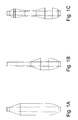
- the typical shape of the spools is shown in figure 1A .
- the thread is wound on a frusto-conical quill with a larger base and a smaller tip.
- the form of the winding is determined by the motion of the bed of the spinning machine moved continuously to lift and lower the spinning rings and to distribute the winding of yarn on the spools wound on their quills to form - from the bottom up - an initial section with spherical progression close to the base, a substantially straight cylindrical middle section with straight generatrix and a more inclined conical section towards the tip.
- a spool having such a shape can be easily and reliably worked in the usual preparation devices that operate with times of the order of 3-5 seconds and that are capable of supplying the spooling stations with the foreseen frequency.
- the usual automatic preparation devices are not capable of working it in the foreseen times and of supplying the spooling stations with the required frequency, thus reducing the overall productivity of the entire production line downstream.
- the present invention is aimed at the control and selection of spools to be fed for spooling, which come in bulk from the spinning process, and at their delivery in the correct position to the transport system of the spooler.
- the present invention in its most general embodiment of a device for selecting and delivering the spool, is defined in the first claim. Variants or preferred embodiments are defined in claims 2 to 7.
- the present invention in its most general embodiment of a process for selecting and delivering the spool, is defined in the eigth claim. Variants or preferred embodiments are defined in claims 9 to 12.
- the spools coming in bulk from the spinning stage are preliminarily singled out, for example through vibrating spiral devices, like in patent US 5,255,775 , which make the spools go up again in line one by one on a spiralled path and send them still in line on a transport path towards the spooler.
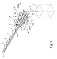
- the transportation path of the spools already singled out consists of the main conveyor belt 1 on which the spools 2 travel flatwise and arranged with their axis parallel to the direction of motion of the conveyor belt, through the effect of directional guides arranged at its sides and not shown in the figures for the sake of clarity of the drawings.
- the spools 2 can lie indistinctly with the base or the tip forwards.
- the prior art - for example DE 19840299 A - describes the identification of the position of the spool based on the measurement of the diameter of its quill: a greater diameter corresponds to the base of the quill that must fall first towards the transportation circuit of the spooler. In the prior art such a measurement is in any case carried out with the spool not moving.
- the first stage of the process according to the invention consists of detecting the profile of the spool 2 that travels flatwise on the main belt 1, actuated at constant speed by its motor 1M. On the conveyor belt 1 some spools with irregular profile are also shown, indicated with 2'. The detection is carried out in the optical sensor 3, arranged on the path of the conveyor belt 1.
- optical sensors that are already available in the state of the art can be used, like for example transmitted light optical sensors consisting of an emitter and a receiver arranged as a portal astride of the transiting spool, or else light reflected optical sensors by the body of the spool with emitter and receiver on the same side, or finally television camera sensors that process the image taken by scanning.
- transmitted light optical sensors consisting of an emitter and a receiver arranged as a portal astride of the transiting spool, or else light reflected optical sensors by the body of the spool with emitter and receiver on the same side
- television camera sensors that process the image taken by scanning.
- the device also comprises a controlling unit G - not indicated in the figures for the sake of simplicity - that receives the signals of the detection relating to the arriving spool from the optical sensor 3 and processes the profile of the spool, on the basis of which it processes and sends the commands to the various other members of the device.
- a controlling unit G - not indicated in the figures for the sake of simplicity - that receives the signals of the detection relating to the arriving spool from the optical sensor 3 and processes the profile of the spool, on the basis of which it processes and sends the commands to the various other members of the device.
- the spool 2 in motion with the belt 1 passes into the portal sensor 3, arranged astride of the conveyor belt 1 and which will be described in greater detail hereafter, arranging itself in the path between the lighting element and the receiving element and creating a shaded area.
- the output signal is therefore proportional to the shade created by the object transiting through the portal sensor 3.
- the signals exiting from the sensor are acquired at regular intervals and a sequence of values representative of the complete profile of the spool that has crossed the sensor is obtained.
- the transiting spool is then treated in varying ways, on the basis of its profile acquired by the controlling unit G processing the signals coming from the initial sensor 3.
- a deviator element 5 onto the path of the main conveyor belt 1 a deviator element 5 is thus placed that deviates, or does not deviate, the spool towards its feeding to the transport system of the spooler.
- Parallel to the conveyor belt 1 at least one secondary sorting conveyor belt 6 is arranged that receives the spools deviated by the deviator element 5 towards the spooler.
- the exemplifying embodiment of figure 2 there are two secondary sorting belts, 6A and 6B, arranged on the two sides A,B of the main conveyor belt 1: in this way, it is possible to increase the capacity and reliability of feeding of the device according to the invention.
- the device can in any case work with reduced capacity with the other secondary sorting belt 6A,B in operation.
- the transiting spools 2' that result having an anomalous and unacceptable profile are left to continue on the conveyor belt 1 and discharged into a collecting box 8 for their subsequent separate treatment.
- the spools with a normal and acceptable profile are deviated towards the spooler.
- the deviator element 5 is realized as a paddle wheel 11, fitted onto a drive shaft 12 set in rotation in steps by a motor 13, controlled by the controlling unit G that receives the signals relating to the arriving spool, as well as information relating to other members of the device, from the portal optical sensor 3, and sends them the operative commands.
- such a deviator element can be realized with compressed air jets, as for the discharging of the sorting belts that are described hereafter.
- the controlling unit G firstly, on the basis of the signals coming from the sensor 3, detects whether the spool has a correct profile: if not, it lets it proceed and does not command the deviator 5. For accepted spools, the controlling unit G instead decides onto which of the two secondary belts 6A,B to deviate the spool with synchronous movement with the arrival of the spools.
- the "normal" decision is for the alternate mode: one to the right and the other to the left in sequence.
- the controlling unit G controls the motor 13 to make the shaft 12 and the paddle wheel 11 rotate by one step with alternate clockwise/anti-clockwise motion, so as to alternately send one spool to the left and one to the right, and to remain "neutral" when it must allow a spool 2' resulted to be irregular on the basis of the reading of its profile to pass.
- the controlling unit G instead controls the motor 13 to make the shaft 12 and the blades 11 rotate by one step at a time, with discontinuous motion or always clockwise or always anti-clockwise, so as to send all of the spools towards the belt that remains operating, still leaving the deviator 5 "neutral" when it must allow a spool 2' resulted to be irregular on the basis of the reading of its profile to pass.
- the synchrony between the arrival of the spool 2 on the conveyor belt 1 at the deviator 5 and the actuation by step of the deviator itself is properly controlled by a sensor arranged on the path of the belt itself.
- the configuration of the two sorting branches to the right and to the left of the belt indicated with letter A or B is identical and parallel.
- the sorting belts 6A,B are actuated by their motors 6MA and 6MB, they move with motion coherent with that of the conveyor belt 1, they receive the spool 2 deviated by the deviator 5 one at a time by falling and lead it to stop against an intercepting bulkhead 15A,B.
- the presence of the spool is controlled by a sensor arranged at the intercepting bulkhead 15A,B itself.
- the spool 2 is then translated transversally by its sorting belt 6A,B towards an orientating device 17A,B that, on the basis of the reading of its profile in the portal sensor 3, positions it with the base downwards so that it falls in upright position on its transport platelet.
- the means for transversally translating the spool 2 are nozzles 19A,B arranged on the opposite side to that of the orientating device 17A,B and that emit compressed air jets: the spool 2 rolls towards the opening of the orientating device 17A,B.
- the orientating device 17A,B is conceptually analogous to the one described in the cited patent US 5,255,775 .
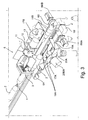
- the orientating device 17A,B consists of a rotary plate 20 with an open recess on the side of its sorting belt 6A,B and consisting of two pairs of supports 21,22 for receiving and horizontally supporting the spool 2; the plate 20 is arranged on a funnel-shaped receiver 24 underneath that carries the falling spool towards its transport platelet after the rotation of the plate 20 that positions it with the base downwards.
- the rotary plate 20 is set in rotation at steps of 90° by a motor 20M, controlled by the controlling unit G: such a rotation is controlled clockwise or anti-clockwise on the basis of the orientation detected with the initial reading of the profile of the spool, thus knowing whether the spool has arrived with the base or with the tip facing forwards.
- the spool 2 has been introduced horizontally into the recess of the immobile plate 20, through the compressed air jets from the nozzles 19, to be rotated in the anti-clockwise direction.
- the plate 20 is then rotated by 90° to cause the spool oriented with its base downwards into the funnel 24 to fall.
- the plate 20 In order to receive a new spool 2 to be oriented the plate 20, with a single recess consisting of the supports 21,22, must be once again rotated to carry its pairs of supports 21,22 in horizontal position.
- the orientating device 17 on the other hand consists of a rotary plate 20 with a cross-shaped recess 25 open on the side of its sorting belt 6A,B, and consisting of four pairs of supports 21,22 and 26,27.
- the plate 20 which has just discharged a spool 2 downwards, is ready to immediately receive a new spool without being rotated again.
- the device and the process for controlling and selecting spools coming in bulk from spinning and for subsequently feeding them to the spooler are controlled by the controlling unit G that, on the basis of the signals that it receives both from the optical sensor 3 and from the various presence sensors of the spool, processes the profile of the spool and sends the commands to carry out the various operations of the cycle in synchrony.
- One of the peculiar characteristics of the present invention is that of operating on the basis of the reading of the complete profile of the spool, detecting it in the optical sensor 3 in which the spool passes in movement.
- a typical embodiment of the detecting optical sensor is shown in an isometric view in figures 6 and 7 , which illustrates a transmitted light optical sensor 3 (emitter and receiver) seen from the left and from the right respectively.
- a series of light emitters 31 and light receivers 32 is respectively arranged, with a pitch of a few mm between each other.
- the passage of the spool 2 in the portal sensor 3 generates a shaded height zone 34 and axially variable along the spool detected with the receivers 32.
- the series of emitter and receivers arranged on the two sides of the portal 3 it operates with a frequency of the order of 1 kHz and with a final resolution of the profile of the spool of the order of 1 mm.
- the spools 2 pass in the portal at constant speed of the order of 30-50 m/min, determined by that of the main conveyor belt 1.
- the flow of the arriving spools is continuous but not ordered: the space intervals between the spools coming out from the vibrating spiral device are not constant.
- the interspace between spool and spool on the belt 1 depends on average on the flow rate of the vibrating spiral device upstream that feeds it. It should not be less than 10 cm, so as not to have interference both in the detection of their profile and, particularly, in their subsequent deviation from the main conveyor belt 1 to the two secondary belts 6A,B.
- Two spools overlapped or embedded, or even simply stuck end to end, are detected as a single spool and generate an unknown profile.
- suitable space the spools for example firstly detecting the distance between the spools exiting from the spiral device and then consequently adjusting the frequency and flow rate of the vibrating spiral device or making the spools that are too close to the preceding spool fall from the spiral device.
- the calibration of the portal sensor is carried out - at the start of the processing of a new batch of spools - with a reading of the profiles of a plurality of sample spools selected as acceptable (of the order of 10-15) and making them pass all laid in the same direction (for example all with the base facing forwards) in the portal sensor, with the self-learning mode of the system.
- the average of the profiles of the 10-15 spools detected in this way constitutes the reference profile for the spools with the base facing forwards.
- the same reference profile seen in the opposite direction constitutes the reference profile for the spools with the tip facing forwards.
- the system consisting of the portal sensor 3 and the controlling unit G thus acquires the profile of every spool that crosses the sensor. Every profile acquired is compared with the reference profiles (with the base or the tip facing forwards) calculating their likeness, for example through the Mathematical Correlation Index, consisting of a correlation coefficient between the sample signal and the detected signal, comprised between values of +1 and -1, according to the usual statistical processing techniques, where the positive values relates to one direction of the spool (for example with the tip facing forwards) and the negative values to the opposite direction.
- the spool is considered to belong to the class for which the likeness index exceeds a certain predetermined absolute value, for example 0.9.
- the spools with a likeness value less than the predetermined value are dubious and thus discarded and to be worked separately.
- the device according to the present invention offers substantial advantages and at least the following ones deserve a mention.
- the present invention preliminarily detects the profile of the spool with the optical detection system.
- detection permits not only to know the posture of the spool and to orient it correctly, but also to adduce to the spooler only the spools suitable for preparation in automatic devices on-board the spooler, discarding the unsuitable spools, with a significant increase in the use factor of the entire production line.
- the detection of the spools is carried out in movement without stopping them and allows the controlling unit G to process the profile and to identify the acceptability and the posture of the spools in times of the order of 10-20 msec.
- the device for selecting spools is capable of feeding two orientating devices 17, sorting them with the sorting device 5 on the two secondary sorting belts 6A,B and the orientating devices 17A,B, doubling their capacity with respect to the single line and fully exploiting the flow rate of the vibrating spiral device that reaches the order of magnitude of 3000-4000 spools/h.
Landscapes
- Engineering & Computer Science (AREA)
- Quality & Reliability (AREA)
- Replacing, Conveying, And Pick-Finding For Filamentary Materials (AREA)
- Spinning Or Twisting Of Yarns (AREA)
Claims (12)
- Eine Vorrichtung zum Steuern der Spulen, die lose von dem Spinnen kommen, und für deren weitere Zuführung für den automatischen Spulvorgang, wobei sich Spulen (2) entlang eines Transportwegs in Richtung einer Ausrichtungsvorrichtung (17) be-wegen, wobei deren Stellung mit einer Einheit erfasst wird, die die Position ihrer Ba-sis erfasst, und deshalb gemäß der Erfassung ihrer Stellung dieselben mit ihrer Basis nach unten dreht, so dass die Spule (2) in einer aufrechten Position auf das Trans-portsystem der Spulmaschine fällt, wobei der Detektor einen optischen Sensor (3) aufweist, der auf dem Weg eines Förderbandes (1) platziert ist, wobei die Spule (2) in einer Bewegung mit dem Band (1) liegend vorbeiläuft, was es dem optischen Sen-sor (3) erlaubt, die Querabmessung der Spule beim Vorübergehen auf dem Förder-band (1) durch Abtastung zu erfassen, und zu einer Steuereinheit G, die von dem op-tischen Sensor (3) die Signale einer derartigen Erfassung empfängt, um das Profil der Spule zu verarbeiten, wobei so das Profil der Spule (2) erhalten wird, sowie ein Ab-lenkelement (5), das die Spule (2) auf zumindest ein sekundäres Sortierförderband (6) ablenkt, das die sortierten Spulen in Richtung der Spulmaschine empfängt, die mit ihrer Basis nach unten ausgerichtet sein sollen, oder es lenkt dieselbe nicht von dem Hauptförderband (1) ab, was diese in Richtung einer Sammelbox (8) der un-normalen Spulen (2') für deren weitere separate Verarbeitung weiterlaufen lässt, wo-bei ein derartiges Ablenkelement (5) auf einen Befehl der Steuereinheit G hin gemäß einem erfassten Profil der Spule (2) oder (2') wirkt, dadurch gekennzeichnet, dass die sekundären Sortierbänder zwei (6A und 6B) sind, die auf beiden Seiten (A, B) des Hauptförderbandes (1) platziert sind, auf die die Spulen mit dem Ablenkelement (5) abgelenkt werden, wobei jedes Band (6A und 6B) eine eigene Ausrichtungsvorrich-tung (17A, B) speist.
- Die Vorrichtung gemäß Anspruch 1, dadurch gekennzeichnet, dass dieselbe einen optischen Portalsensor (3) durchgelassenen Lichts aufweist, der rittlings zu einem Förderband (1) platziert ist, wobei die Spule (2) in einer Bewegung mit dem Band (1) liegend vorbeiläuft, was eine Schattenzone erzeugt.
- Die Vorrichtung gemäß Anspruch 1, dadurch gekennzeichnet, dass das Ablenkele-ment (5) als ein Schaufelrad (11) ausgeführt ist, das an einer Antriebswelle (12) ver-zahnt ist, die durch einen Motor (13) in Schritten in Drehung bewegt wird.
- Die Vorrichtung gemäß Anspruch 3, dadurch gekennzeichnet, dass das Ablenkele-ment (5) mit einer Einrichtung für die schrittweise Betätigung mit einer abwechseln-den Bewegung im Uhrzeigersinn/gegen den Uhrzeigersinn, um so abwechselnd eine Spule links und eine rechts zu leiten, wobei die beiden Bänder arbeiten, oder für die schrittweise Betätigung immer in der gleichen Richtung, um so alle Spulen in Rich-tung des Bandes, das in Betrieb bleibt, zu leiten, versehen ist.
- Die Vorrichtung gemäß Anspruch 3, dadurch gekennzeichnet, dass das Ablenkele-ment (5) mit einer Einrichtung für die schrittweise Betätigung zum Ablenken der Spule, rechts oder links, gemäß dem Frei/Besetzt-Zustand der beiden sekundären Förderbänder (6A, B) versehen ist.
- Die Vorrichtung gemäß Anspruch 3, dadurch gekennzeichnet, dass der Weg der bei-den sekundären Sortierbänder (6A und 6B) durch eine Abfang-Trennwand (15A, B) abgeschnitten wird, und wobei an der Trennwand (15A, B) Querverschiebungsein-richtungen (19A, B) der Spule (2) angeordnet sind, von jedem Sortierband (6A, B) in Richtung ihrer eigenen Ausrichtungsvorrichtung (17A, B), um diese mit ihrer Basis nach unten zu platzieren.
- Die Vorrichtung gemäß Anspruch 3, dadurch gekennzeichnet, dass die Einrichtungen für die Querverschiebung der Spule (2) aus Düsen (19A, B) bestehen, die an der Sei-te gegenüber derjenigen der Ausrichtungsvorrichtung (17A, B) platziert sind, und die Pressluftstrahlen ausstoßen.
- Ein Verfahren zum Steuern der Spulen, die lose von dem Spinnen kommen, und zum nachfolgenden Zuführen derselben für den automatischen Spulvorgang, das für ein vorläufiges individuelles Vereinzeln derselben sorgt, durch Anordnen derselben eine nach der anderen in Reihen und derartiges Zuführen derselben zu dem automatischen Spulvorgang, wobei die Spulen (2) einer Ausrichtungsvorrichtung (17) zugeführt werden, wobei diese gemäß der Erfassung ihrer Stellung dieselben mit ihrer Basis nach unten dreht, damit diese in eine aufrechte Position fallen, wobei die Spulen (2) auf einem Hauptförderband (1) transportiert werden, auf dem die Erfassung des Pro-fils der Spule (2) durch einen optischen Sensor (3) ausgeführt wird, der entlang des Wegs des Förderbandes (1) platziert ist, auf dem die Spule (2) in einer Bewegung mit dem Band (1) liegend vorbeiläuft, was es dem optischen Sensor (3) erlaubt, die Querabmessung der Spule beim Vorübergehen auf dem Förderband (1) durch Abtas-tung zu erfassen, sowie eine Steuereinheit G, die von dem optischen Sensor (3) die Signale einer derartigen Erfassung empfängt, um das Profil der Spule zu verarbeiten, wobei das Profil mit einem Referenzprofil verglichen wird, um so die Ausrichtung der Spule nachzuverfolgen und die normalen Spulen (2) von den unnormalen (2') zu unterscheiden; und dass gemäß einer derartigen Identifizierung die Ablenkung der Spulen durch ein Ablenkelement (5) durchgeführt wird, das die normale Spule (2) auf zumindest ein sekundäres Sortierförderband (6) ablenkt, das die abgelenkten Spulen in Richtung der Spulmaschine empfängt, und die mit ihrer Basis nach unten ausgerichtet werden sollen, oder es lenkt die unnormalen Spulen (2') nicht von dem Hauptförderband (1) ab und lässt dieselben in Richtung einer Sammelbox (8) für de-ren nachfolgende separate Verarbeitung weiterlaufen, wobei eine derartige Ablenkung durch eine Steuereinheit G gemäß dem erfassten Profil der Spule (2) oder (2') gesteuert wird, dadurch gekennzeichnet, dass die sekundären Sortierbänder zwei (6A und 6B) sind, die auf beiden Seiten (A, B) des Hauptförderbandes (1) platziert sind, auf die die Spulen mit dem Ablenkelement (5) abgelenkt werden, wobei jedes Band (6A und 6B) eine eigene Ausrichtungsvorrichtung (17A, B) speist.
- Das Verfahren gemäß Anspruch 8, dadurch gekennzeichnet, dass die Erfassung mit einem optischen Portalsensor (3) durchgelassenen Lichts, rittlings zu einem Förder-band (1), ausgeführt wird, wobei die Spule (2) in einer Bewegung mit dem Band (1) liegend vorbeiläuft, was eine Schattenzone erzeugt.
- Das Verfahren gemäß Anspruch 8, dadurch gekennzeichnet, dass das Ablenkelement (5) abwechselnd eine Spule links und eine rechts leitet.
- Das Verfahren gemäß Anspruch 8, dadurch gekennzeichnet, dass das Ablenkelement (5) die Spule rechts oder links gemäß dem Frei/Besetzt-Zustand der beiden sekundä-ren Förderbänder (6A, B) leitet.
- Das Verfahren gemäß Anspruch 8, dadurch gekennzeichnet, dass die Kalibrierung des Portalsensors (3) zu Beginn der Verarbeitung einer neuen Ladung Spulen ausge-führt wird, durch Lesen der Profile einer Mehrzahl gleicher Spulen, indem ein lie-gendes Vorbeilaufen derselben, alle in der gleichen Richtung in dem Portalsensor bewirkt wird, mit dem Selbstlernmodus des Systems, wobei der Durchschnitt der Profile der Spulen, die mit einem derartigen Modus erfasst werden, das Referenzpro-fil für die Spulen in dieser Richtung darstellt, wobei das gleiche Referenzprofil in der entgegengesetzten Richtung betrachtet das Referenzprofil für die Spulen in der ent-gegengesetzten Richtung ist.
Applications Claiming Priority (1)
| Application Number | Priority Date | Filing Date | Title |
|---|---|---|---|
| ITMI2010A002331A IT1403277B1 (it) | 2010-12-20 | 2010-12-20 | Dispositivo e procedimento per il controllo e l'alimentazione ad una roccatrice automatica di spole provenienti alla rinfusa dalla filatura |
Publications (2)
| Publication Number | Publication Date |
|---|---|
| EP2465801A1 EP2465801A1 (de) | 2012-06-20 |
| EP2465801B1 true EP2465801B1 (de) | 2013-06-05 |
Family
ID=43736986
Family Applications (1)
| Application Number | Title | Priority Date | Filing Date |
|---|---|---|---|
| EP20110194114 Active EP2465801B1 (de) | 2010-12-20 | 2011-12-16 | Vorrichtung und Verfahren zum Steuern und Zuführen von als Schüttgut aus der Spinnerei kommenden Spulen zu einer automatischen Spulmaschine |
Country Status (3)
| Country | Link |
|---|---|
| EP (1) | EP2465801B1 (de) |
| CN (1) | CN102658950B (de) |
| IT (1) | IT1403277B1 (de) |
Cited By (1)
| Publication number | Priority date | Publication date | Assignee | Title |
|---|---|---|---|---|
| EP3309098A1 (de) | 2016-10-17 | 2018-04-18 | Murata Machinery, Ltd. | Trägerverteilungsvorrichtung |
Families Citing this family (5)
| Publication number | Priority date | Publication date | Assignee | Title |
|---|---|---|---|---|
| JP2016155632A (ja) * | 2015-02-24 | 2016-09-01 | 村田機械株式会社 | 給糸ボビン分配装置及びボビン供給システム |
| CN105600400B (zh) * | 2016-02-24 | 2017-09-12 | 江阴市凯业纺织机械制造有限公司 | 理管装置及理管方法 |
| CN105819278A (zh) * | 2016-04-22 | 2016-08-03 | 青岛宏大纺织机械有限责任公司 | 自动络筒机插管装置及插管方法 |
| CN105819199B (zh) * | 2016-04-22 | 2018-08-07 | 青岛宏大纺织机械有限责任公司 | 一种自动络筒机插管装置及插管方法 |
| CN108733916B (zh) * | 2018-05-17 | 2022-09-02 | 中船黄埔文冲船舶有限公司 | 一种撑线展开法的交叉线的求取方法及装置 |
Family Cites Families (12)
| Publication number | Priority date | Publication date | Assignee | Title |
|---|---|---|---|---|
| GB957162A (en) * | 1959-07-10 | 1964-05-06 | Cotton Silk & Man Made Fibres | Article sorting means |
| JPS4963460A (de) * | 1972-10-17 | 1974-06-19 | ||
| JPS56120019A (en) | 1980-02-26 | 1981-09-21 | Mitsubishi Electric Corp | Operating mechanism for switch |
| JPS6246662U (de) * | 1985-09-09 | 1987-03-23 | ||
| JPS6260778A (ja) * | 1985-09-10 | 1987-03-17 | Kurabo Ind Ltd | ボビンの自動選別装置 |
| DE3844845C2 (de) * | 1988-12-23 | 1994-03-31 | Schlafhorst & Co W | Spulautomat |
| DE3942304A1 (de) * | 1989-12-21 | 1991-06-27 | Schlafhorst & Co W | Verfahren und vorrichtung zur qualitativen und quantitativen erfassung eines garnwickels und zum ableiten definierter steuervorgaenge daraus |
| DE4112435C2 (de) * | 1991-04-16 | 2000-07-06 | Schlafhorst & Co W | Kopslieferstation |
| DE19636661A1 (de) * | 1996-09-10 | 1998-03-12 | Schlafhorst & Co W | Transportsystem für eine Textilmaschine |
| DE19840299A1 (de) * | 1998-09-04 | 2000-03-09 | Schlafhorst & Co W | Vorrichtung zur Erkennung der Orientierung von Kopsen |
| EP1905875B1 (de) * | 2006-09-29 | 2010-03-10 | Maschinenfabrik Rieter Ag | Spulen- bzw. Hülsentransportvorrichtung einer Spinnmaschine |
| DE102008031596A1 (de) * | 2008-07-03 | 2010-01-07 | Oerlikon Textile Gmbh & Co. Kg | Spinnkops- und Hülsentransportsystem |
-
2010
- 2010-12-20 IT ITMI2010A002331A patent/IT1403277B1/it active
-
2011
- 2011-12-16 EP EP20110194114 patent/EP2465801B1/de active Active
- 2011-12-20 CN CN201110463376.2A patent/CN102658950B/zh active Active
Cited By (1)
| Publication number | Priority date | Publication date | Assignee | Title |
|---|---|---|---|---|
| EP3309098A1 (de) | 2016-10-17 | 2018-04-18 | Murata Machinery, Ltd. | Trägerverteilungsvorrichtung |
Also Published As
| Publication number | Publication date |
|---|---|
| CN102658950B (zh) | 2016-05-04 |
| ITMI20102331A1 (it) | 2012-06-21 |
| CN102658950A (zh) | 2012-09-12 |
| IT1403277B1 (it) | 2013-10-17 |
| EP2465801A1 (de) | 2012-06-20 |
Similar Documents
| Publication | Publication Date | Title |
|---|---|---|
| EP2465801B1 (de) | Vorrichtung und Verfahren zum Steuern und Zuführen von als Schüttgut aus der Spinnerei kommenden Spulen zu einer automatischen Spulmaschine | |
| US4565278A (en) | Method of transferring yarn packages | |
| CN104709770B (zh) | 操作络筒机的方法以及络筒机 | |
| US5142159A (en) | Method and apparatus for volume or size detection of a yarn package and for deriving confined control processes therefrom | |
| JPH0388680A (ja) | 自動式のワインダ | |
| US4776468A (en) | Bobbin conveying system | |
| JPS6356153B2 (de) | ||
| US4613091A (en) | Cop transporting system for an automatic winder | |
| EP3718939B1 (de) | Vorrichtung und verfahren zur erkennung des vorhandenseins von abnormalitäten in einer rolle | |
| JP6738184B2 (ja) | 少なくとも1つのリング精紡機と少なくとも1つの巻取り機とから成る複合システムを運転する方法並びに複合システム | |
| JPH05155424A (ja) | コップ供給ステーション | |
| CN101168419A (zh) | 预处理纱管以便在自动交叉卷绕络筒机上复绕的方法和装置 | |
| KR20160127678A (ko) | 섬유 기계의 작업 스테이션에서 움직이는 실에 의해 형성된 실 발루운의 직경을 결정하는 장치 및 방법 | |
| US5226778A (en) | Yarn supply device for automatic winder | |
| JP7085937B2 (ja) | 糸から糸欠陥をクリアリング除去する装置 | |
| EP0145981B1 (de) | Handhaben von Kreuzspulen | |
| JPH0388681A (ja) | 自動式のワインダ | |
| JP2016108156A (ja) | 紡績コップを製造しかつさらに処理する方法 | |
| EP1764333B1 (de) | Verfahren und Vorrichtung zum Wickeln von Garn und so hergestelltes Garnbündel | |
| US4558776A (en) | Apparatus for arranging cross-wound packages on an auxiliary transport belt | |
| JPH08324891A (ja) | 糸端探索装置 | |
| CN108203852B (zh) | 开端式纺纱设备和用于从其卸载卷装的方法 | |
| US5495990A (en) | Method and apparatus for removing wrapped yarn group on package bobbin end | |
| JPH10167578A (ja) | 巻き管をセンタリングするための装置 | |
| CN112823220A (zh) | 熔纺装置操作方法和熔纺装置 |
Legal Events
| Date | Code | Title | Description |
|---|---|---|---|
| PUAI | Public reference made under article 153(3) epc to a published international application that has entered the european phase |
Free format text: ORIGINAL CODE: 0009012 |
|
| AK | Designated contracting states |
Kind code of ref document: A1 Designated state(s): AL AT BE BG CH CY CZ DE DK EE ES FI FR GB GR HR HU IE IS IT LI LT LU LV MC MK MT NL NO PL PT RO RS SE SI SK SM TR |
|
| AX | Request for extension of the european patent |
Extension state: BA ME |
|
| RAP1 | Party data changed (applicant data changed or rights of an application transferred) |
Owner name: SAVIO MACCHINE TESSILI S.P.A. |
|
| RAP1 | Party data changed (applicant data changed or rights of an application transferred) |
Owner name: SAVIO MACCHINE TESSILI S.P.A. |
|
| 17P | Request for examination filed |
Effective date: 20121119 |
|
| GRAP | Despatch of communication of intention to grant a patent |
Free format text: ORIGINAL CODE: EPIDOSNIGR1 |
|
| RIC1 | Information provided on ipc code assigned before grant |
Ipc: B65H 63/00 20060101AFI20130107BHEP Ipc: B65H 67/06 20060101ALI20130107BHEP |
|
| GRAS | Grant fee paid |
Free format text: ORIGINAL CODE: EPIDOSNIGR3 |
|
| GRAA | (expected) grant |
Free format text: ORIGINAL CODE: 0009210 |
|
| AK | Designated contracting states |
Kind code of ref document: B1 Designated state(s): AL AT BE BG CH CY CZ DE DK EE ES FI FR GB GR HR HU IE IS IT LI LT LU LV MC MK MT NL NO PL PT RO RS SE SI SK SM TR |
|
| REG | Reference to a national code |
Ref country code: GB Ref legal event code: FG4D |
|
| REG | Reference to a national code |
Ref country code: CH Ref legal event code: EP |
|
| REG | Reference to a national code |
Ref country code: AT Ref legal event code: REF Ref document number: 615567 Country of ref document: AT Kind code of ref document: T Effective date: 20130615 |
|
| REG | Reference to a national code |
Ref country code: CH Ref legal event code: NV Representative=s name: JACOBACCI AND PARTNERS S.P.A., CH |
|
| REG | Reference to a national code |
Ref country code: IE Ref legal event code: FG4D |
|
| REG | Reference to a national code |
Ref country code: DE Ref legal event code: R096 Ref document number: 602011001943 Country of ref document: DE Effective date: 20130801 |
|
| REG | Reference to a national code |
Ref country code: AT Ref legal event code: MK05 Ref document number: 615567 Country of ref document: AT Kind code of ref document: T Effective date: 20130605 |
|
| PG25 | Lapsed in a contracting state [announced via postgrant information from national office to epo] |
Ref country code: SE Free format text: LAPSE BECAUSE OF FAILURE TO SUBMIT A TRANSLATION OF THE DESCRIPTION OR TO PAY THE FEE WITHIN THE PRESCRIBED TIME-LIMIT Effective date: 20130605 Ref country code: LT Free format text: LAPSE BECAUSE OF FAILURE TO SUBMIT A TRANSLATION OF THE DESCRIPTION OR TO PAY THE FEE WITHIN THE PRESCRIBED TIME-LIMIT Effective date: 20130605 Ref country code: FI Free format text: LAPSE BECAUSE OF FAILURE TO SUBMIT A TRANSLATION OF THE DESCRIPTION OR TO PAY THE FEE WITHIN THE PRESCRIBED TIME-LIMIT Effective date: 20130605 Ref country code: GR Free format text: LAPSE BECAUSE OF FAILURE TO SUBMIT A TRANSLATION OF THE DESCRIPTION OR TO PAY THE FEE WITHIN THE PRESCRIBED TIME-LIMIT Effective date: 20130906 Ref country code: ES Free format text: LAPSE BECAUSE OF FAILURE TO SUBMIT A TRANSLATION OF THE DESCRIPTION OR TO PAY THE FEE WITHIN THE PRESCRIBED TIME-LIMIT Effective date: 20130916 Ref country code: AT Free format text: LAPSE BECAUSE OF FAILURE TO SUBMIT A TRANSLATION OF THE DESCRIPTION OR TO PAY THE FEE WITHIN THE PRESCRIBED TIME-LIMIT Effective date: 20130605 Ref country code: SI Free format text: LAPSE BECAUSE OF FAILURE TO SUBMIT A TRANSLATION OF THE DESCRIPTION OR TO PAY THE FEE WITHIN THE PRESCRIBED TIME-LIMIT Effective date: 20130605 Ref country code: NO Free format text: LAPSE BECAUSE OF FAILURE TO SUBMIT A TRANSLATION OF THE DESCRIPTION OR TO PAY THE FEE WITHIN THE PRESCRIBED TIME-LIMIT Effective date: 20130905 |
|
| REG | Reference to a national code |
Ref country code: NL Ref legal event code: VDEP Effective date: 20130605 |
|
| REG | Reference to a national code |
Ref country code: LT Ref legal event code: MG4D |
|
| PG25 | Lapsed in a contracting state [announced via postgrant information from national office to epo] |
Ref country code: HR Free format text: LAPSE BECAUSE OF FAILURE TO SUBMIT A TRANSLATION OF THE DESCRIPTION OR TO PAY THE FEE WITHIN THE PRESCRIBED TIME-LIMIT Effective date: 20130605 Ref country code: RS Free format text: LAPSE BECAUSE OF FAILURE TO SUBMIT A TRANSLATION OF THE DESCRIPTION OR TO PAY THE FEE WITHIN THE PRESCRIBED TIME-LIMIT Effective date: 20130605 Ref country code: BG Free format text: LAPSE BECAUSE OF FAILURE TO SUBMIT A TRANSLATION OF THE DESCRIPTION OR TO PAY THE FEE WITHIN THE PRESCRIBED TIME-LIMIT Effective date: 20130905 |
|
| PG25 | Lapsed in a contracting state [announced via postgrant information from national office to epo] |
Ref country code: LV Free format text: LAPSE BECAUSE OF FAILURE TO SUBMIT A TRANSLATION OF THE DESCRIPTION OR TO PAY THE FEE WITHIN THE PRESCRIBED TIME-LIMIT Effective date: 20130605 |
|
| PG25 | Lapsed in a contracting state [announced via postgrant information from national office to epo] |
Ref country code: BE Free format text: LAPSE BECAUSE OF FAILURE TO SUBMIT A TRANSLATION OF THE DESCRIPTION OR TO PAY THE FEE WITHIN THE PRESCRIBED TIME-LIMIT Effective date: 20130605 Ref country code: SK Free format text: LAPSE BECAUSE OF FAILURE TO SUBMIT A TRANSLATION OF THE DESCRIPTION OR TO PAY THE FEE WITHIN THE PRESCRIBED TIME-LIMIT Effective date: 20130605 Ref country code: IS Free format text: LAPSE BECAUSE OF FAILURE TO SUBMIT A TRANSLATION OF THE DESCRIPTION OR TO PAY THE FEE WITHIN THE PRESCRIBED TIME-LIMIT Effective date: 20131005 Ref country code: EE Free format text: LAPSE BECAUSE OF FAILURE TO SUBMIT A TRANSLATION OF THE DESCRIPTION OR TO PAY THE FEE WITHIN THE PRESCRIBED TIME-LIMIT Effective date: 20130605 Ref country code: PT Free format text: LAPSE BECAUSE OF FAILURE TO SUBMIT A TRANSLATION OF THE DESCRIPTION OR TO PAY THE FEE WITHIN THE PRESCRIBED TIME-LIMIT Effective date: 20131007 |
|
| PG25 | Lapsed in a contracting state [announced via postgrant information from national office to epo] |
Ref country code: NL Free format text: LAPSE BECAUSE OF FAILURE TO SUBMIT A TRANSLATION OF THE DESCRIPTION OR TO PAY THE FEE WITHIN THE PRESCRIBED TIME-LIMIT Effective date: 20130605 Ref country code: RO Free format text: LAPSE BECAUSE OF FAILURE TO SUBMIT A TRANSLATION OF THE DESCRIPTION OR TO PAY THE FEE WITHIN THE PRESCRIBED TIME-LIMIT Effective date: 20130605 Ref country code: PL Free format text: LAPSE BECAUSE OF FAILURE TO SUBMIT A TRANSLATION OF THE DESCRIPTION OR TO PAY THE FEE WITHIN THE PRESCRIBED TIME-LIMIT Effective date: 20130605 |
|
| PLBE | No opposition filed within time limit |
Free format text: ORIGINAL CODE: 0009261 |
|
| STAA | Information on the status of an ep patent application or granted ep patent |
Free format text: STATUS: NO OPPOSITION FILED WITHIN TIME LIMIT |
|
| PG25 | Lapsed in a contracting state [announced via postgrant information from national office to epo] |
Ref country code: DK Free format text: LAPSE BECAUSE OF FAILURE TO SUBMIT A TRANSLATION OF THE DESCRIPTION OR TO PAY THE FEE WITHIN THE PRESCRIBED TIME-LIMIT Effective date: 20130605 |
|
| 26N | No opposition filed |
Effective date: 20140306 |
|
| REG | Reference to a national code |
Ref country code: DE Ref legal event code: R097 Ref document number: 602011001943 Country of ref document: DE Effective date: 20140306 |
|
| PG25 | Lapsed in a contracting state [announced via postgrant information from national office to epo] |
Ref country code: MC Free format text: LAPSE BECAUSE OF FAILURE TO SUBMIT A TRANSLATION OF THE DESCRIPTION OR TO PAY THE FEE WITHIN THE PRESCRIBED TIME-LIMIT Effective date: 20130605 |
|
| PG25 | Lapsed in a contracting state [announced via postgrant information from national office to epo] |
Ref country code: LU Free format text: LAPSE BECAUSE OF FAILURE TO SUBMIT A TRANSLATION OF THE DESCRIPTION OR TO PAY THE FEE WITHIN THE PRESCRIBED TIME-LIMIT Effective date: 20131216 |
|
| REG | Reference to a national code |
Ref country code: IE Ref legal event code: MM4A |
|
| REG | Reference to a national code |
Ref country code: FR Ref legal event code: ST Effective date: 20140829 |
|
| PG25 | Lapsed in a contracting state [announced via postgrant information from national office to epo] |
Ref country code: IE Free format text: LAPSE BECAUSE OF NON-PAYMENT OF DUE FEES Effective date: 20131216 |
|
| PG25 | Lapsed in a contracting state [announced via postgrant information from national office to epo] |
Ref country code: FR Free format text: LAPSE BECAUSE OF NON-PAYMENT OF DUE FEES Effective date: 20131231 |
|
| REG | Reference to a national code |
Ref country code: CH Ref legal event code: PCAR Free format text: NEW ADDRESS: VIA LUGANETTO 3, 6962 LUGANO (CH) |
|
| PG25 | Lapsed in a contracting state [announced via postgrant information from national office to epo] |
Ref country code: SM Free format text: LAPSE BECAUSE OF FAILURE TO SUBMIT A TRANSLATION OF THE DESCRIPTION OR TO PAY THE FEE WITHIN THE PRESCRIBED TIME-LIMIT Effective date: 20130605 |
|
| PG25 | Lapsed in a contracting state [announced via postgrant information from national office to epo] |
Ref country code: CY Free format text: LAPSE BECAUSE OF FAILURE TO SUBMIT A TRANSLATION OF THE DESCRIPTION OR TO PAY THE FEE WITHIN THE PRESCRIBED TIME-LIMIT Effective date: 20130605 |
|
| PG25 | Lapsed in a contracting state [announced via postgrant information from national office to epo] |
Ref country code: HU Free format text: LAPSE BECAUSE OF FAILURE TO SUBMIT A TRANSLATION OF THE DESCRIPTION OR TO PAY THE FEE WITHIN THE PRESCRIBED TIME-LIMIT; INVALID AB INITIO Effective date: 20111216 Ref country code: MK Free format text: LAPSE BECAUSE OF FAILURE TO SUBMIT A TRANSLATION OF THE DESCRIPTION OR TO PAY THE FEE WITHIN THE PRESCRIBED TIME-LIMIT Effective date: 20130605 |
|
| PG25 | Lapsed in a contracting state [announced via postgrant information from national office to epo] |
Ref country code: MT Free format text: LAPSE BECAUSE OF FAILURE TO SUBMIT A TRANSLATION OF THE DESCRIPTION OR TO PAY THE FEE WITHIN THE PRESCRIBED TIME-LIMIT Effective date: 20130605 |
|
| GBPC | Gb: european patent ceased through non-payment of renewal fee |
Effective date: 20151216 |
|
| PG25 | Lapsed in a contracting state [announced via postgrant information from national office to epo] |
Ref country code: GB Free format text: LAPSE BECAUSE OF NON-PAYMENT OF DUE FEES Effective date: 20151216 |
|
| PG25 | Lapsed in a contracting state [announced via postgrant information from national office to epo] |
Ref country code: AL Free format text: LAPSE BECAUSE OF FAILURE TO SUBMIT A TRANSLATION OF THE DESCRIPTION OR TO PAY THE FEE WITHIN THE PRESCRIBED TIME-LIMIT Effective date: 20130605 |
|
| PGFP | Annual fee paid to national office [announced via postgrant information from national office to epo] |
Ref country code: CZ Payment date: 20211027 Year of fee payment: 11 Ref country code: DE Payment date: 20211210 Year of fee payment: 11 |
|
| PGFP | Annual fee paid to national office [announced via postgrant information from national office to epo] |
Ref country code: CH Payment date: 20211221 Year of fee payment: 11 |
|
| REG | Reference to a national code |
Ref country code: DE Ref legal event code: R119 Ref document number: 602011001943 Country of ref document: DE |
|
| P01 | Opt-out of the competence of the unified patent court (upc) registered |
Effective date: 20230526 |
|
| PG25 | Lapsed in a contracting state [announced via postgrant information from national office to epo] |
Ref country code: CZ Free format text: LAPSE BECAUSE OF NON-PAYMENT OF DUE FEES Effective date: 20221216 |
|
| REG | Reference to a national code |
Ref country code: CH Ref legal event code: PL |
|
| PG25 | Lapsed in a contracting state [announced via postgrant information from national office to epo] |
Ref country code: LI Free format text: LAPSE BECAUSE OF NON-PAYMENT OF DUE FEES Effective date: 20221231 Ref country code: DE Free format text: LAPSE BECAUSE OF NON-PAYMENT OF DUE FEES Effective date: 20230701 Ref country code: CH Free format text: LAPSE BECAUSE OF NON-PAYMENT OF DUE FEES Effective date: 20221231 |
|
| PGFP | Annual fee paid to national office [announced via postgrant information from national office to epo] |
Ref country code: IT Payment date: 20251007 Year of fee payment: 15 |
|
| PGFP | Annual fee paid to national office [announced via postgrant information from national office to epo] |
Ref country code: TR Payment date: 20251130 Year of fee payment: 15 |