EP2465131B1 - X-ray tube with independent x- and z- dynamic focal spot deflection - Google Patents
X-ray tube with independent x- and z- dynamic focal spot deflection Download PDFInfo
- Publication number
- EP2465131B1 EP2465131B1 EP10742905.2A EP10742905A EP2465131B1 EP 2465131 B1 EP2465131 B1 EP 2465131B1 EP 10742905 A EP10742905 A EP 10742905A EP 2465131 B1 EP2465131 B1 EP 2465131B1
- Authority
- EP
- European Patent Office
- Prior art keywords
- ray tube
- deflection device
- deflection
- focal spot
- ray
- Prior art date
- Legal status (The legal status is an assumption and is not a legal conclusion. Google has not performed a legal analysis and makes no representation as to the accuracy of the status listed.)
- Active
Links
Images


Classifications
-
- H—ELECTRICITY
- H01—ELECTRIC ELEMENTS
- H01J—ELECTRIC DISCHARGE TUBES OR DISCHARGE LAMPS
- H01J35/00—X-ray tubes
- H01J35/24—Tubes wherein the point of impact of the cathode ray on the anode or anticathode is movable relative to the surface thereof
- H01J35/26—Tubes wherein the point of impact of the cathode ray on the anode or anticathode is movable relative to the surface thereof by rotation of the anode or anticathode
-
- A—HUMAN NECESSITIES
- A61—MEDICAL OR VETERINARY SCIENCE; HYGIENE
- A61B—DIAGNOSIS; SURGERY; IDENTIFICATION
- A61B6/00—Apparatus or devices for radiation diagnosis; Apparatus or devices for radiation diagnosis combined with radiation therapy equipment
- A61B6/40—Arrangements for generating radiation specially adapted for radiation diagnosis
- A61B6/4021—Arrangements for generating radiation specially adapted for radiation diagnosis involving movement of the focal spot
-
- H—ELECTRICITY
- H01—ELECTRIC ELEMENTS
- H01J—ELECTRIC DISCHARGE TUBES OR DISCHARGE LAMPS
- H01J35/00—X-ray tubes
- H01J35/02—Details
- H01J35/14—Arrangements for concentrating, focusing, or directing the cathode ray
- H01J35/153—Spot position control
-
- A—HUMAN NECESSITIES
- A61—MEDICAL OR VETERINARY SCIENCE; HYGIENE
- A61B—DIAGNOSIS; SURGERY; IDENTIFICATION
- A61B6/00—Apparatus or devices for radiation diagnosis; Apparatus or devices for radiation diagnosis combined with radiation therapy equipment
- A61B6/02—Arrangements for diagnosis sequentially in different planes; Stereoscopic radiation diagnosis
- A61B6/03—Computed tomography [CT]
- A61B6/032—Transmission computed tomography [CT]
Definitions
- the present invention relates to an X-ray tube and an X-ray system including such a tube.
- the invention relates to an X-ray tube including means for deflection of the focal spot in x-direction and in y-direction (hence in z-direction).
- the invention relates to a computer program for controlling an X-ray system including such an X-ray tube.
- Double-x sampling is accomplished by oscillating the focal spot about its static position in a path tangential to the target focal track.
- the spot is displaced by approximately +/- 1/2 pixel either by using electrostatic grids or by an electromagnet.
- double-x sampling the electron beam/focal spot is deflected laterally to the filament/cathode at a prescribed frequency in the x-direction, tangential to the target focal track. Samples are taken at each extreme position so that one image contains information obtained at two viewing angles and contains virtually twice the information in a static image.
- the concept of double-z sampling, z-flying focal spot sampling or z-dynamic focal spot sampling has been established in the CT art as a mean of increasing resolution and decreasing artefacts.
- the method involves causing the focal spot to alternate between two z-positions, thus acquiring two slices per detector row, effectively double sampling in the z-direction. For example, with 32 rows of detectors, this technique effectively measures 64 slices.
- Double-z sampling is accomplished essentially by moving the focal spot along a vector primarily directed in the y-direction on the target focal track. Because the focal track is at an angle with regard to the plane of the target (typically 7 or 8 degrees), movement of the focal spot in the y-direction causes it to also move in the z-direction, the distance being proportional to the sine of the target angle.
- the net effect of double-z sampling is to alternate the focal spot between two z-positions on the detector rows. This effectively acquires two overlapping slices per detector row, for example obtaining 64 slices in 32 rows. It is thus seen that double-z sampling can, in effect, double the slice capability of a CT scanner, turning a 32 slice scanner into a 64 slice scanner.
- JP 2009 158138 A discloses an X-ray tube and an X-ray CT device capable of controlling an irradiation position of the X-ray with superior precision.
- a pair of electrodes in which a coil filament to discharge an electron by energization and an anode to emit the X-ray by incidence of the electron are installed. This document also discloes that a coil is placed outside the X-ray tube housing.
- an X-ray tube adapted to generate X-ray beams, comprising a first deflection device for focal spot deflection in the x-direction, a second deflection device for focal spot deflection in the y-direction, and a cathode housing, wherein the first deflection device is mounted in the cathode housing and the second deflection device is mounted outside the housing, and wherein the first and second deflection devices are arranged separately from each other along the z-axis of the X-ray tube.
- the first deflection device is formed by electrostatic grids, and is mounted on the cathode cup. Even if two electrostatic grids may be usually utilized, it may be advantageous to have more than two grids.
- the second deflection device includes an electromagnetic coil forming a dipole, and is mounted between a cathode and an anode of the X-ray tube.
- the simple dipole electromagnet requires only a small amount of magnetic material to produce required magnetic fields and hence the reluctance can be quite low, facilitating rapidly oscillating the magnetic field.
- the second deflection device may also provide for focal spot deflection in x-direction, so that the second deflection device deflects the focal spot diagonally between the x- and y-direction.
- the second deflection device is rotated slightly from true y-direction to produce a diagonal deflection of the focal spot.
- the first deflection device then may be used for (1) x-deflection when this alone is desired, (2) cancelling or modifying the x-portion of the diagonal deflection if y-deflection alone is desired or a different amount is desired in the diagonal deflection.
- the first deflection device as well as the second deflection device may be operated to generate a static field or a dynamic field or a combination of the same, i.e. a static field superimposed by a dynamic field.
- both deflection devices may be operated with a variety of polarities.
- the focal spot can be shaped and positioned by use of static fields and can be oscillated about this position by superimposing dynamic fields upon a static field.
- the cathode of the X-ray tube may comprise more than one filament.
- two filaments may be positioned in such a way that the corresponding electron beams impinge the anode at different focal spots. It may also be advantageous to have filaments with different sizes.
- an X-ray system comprises an X-ray tube as mentioned above, a detector for the detection of X-ray beams, and a processing unit.
- a system may further comprise a motor control unit controlling a motion of the X-ray tube and detector relative to an object of interest, and at the same time or independently controlling a motion of the object of interest itself.
- Such an X-ray system may be for example a computer tomography system.
- the invention may also relate to a computer program for a processing unit of a system as mentioned above.
- the computer program may be adapted to control the deflection of the focal spot in x-direction as well as in y-direction (which results in a deflection in z-direction).
- the computer program may control the first deflection device as well as the separately arranged second deflection device.
- the computer program may also include instruction for processing the data received from the detector as basis for images which may be illustrated on a monitor of the system, controlled by the computer program.
- the computer program may also include instruction for controlling motion of the X-ray tube and detector relative to an object of interest, and for controlling motion of the object of interest itself relative to the X-ray tube and detector.
- the computer program is preferably loaded into a working memory of a data processor.
- the data processor is thus equipped to carry out a method of the invention.
- the invention relates to a computer-readable medium, such as a CD-ROM, at which the computer program may be stored.
- the computer program may also be presented over a network like the WorldWideWeb and can be downloaded into the working memory of the data processor from such a network.
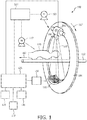
- Fig. 1 shows an X-ray system 100 according to the invention.
- the X-ray system may be a computer tomography system, which is also called a CT scanner and in which the X-ray tube according to the invention can be used.
- the CT scanner 100 comprises a gantry 101, which is rotatable around a rotational axis 102.
- the gantry 101 is driven by means of a motor 103.
- Reference number 200 designates a source of radiation such as an X-ray tube according to the invention, which may emit a polychromatic radiation 107.
- the CT scanner 100 further comprises an aperture system 106, which forms the X-radiation being emitted from the X-ray source 200 into a radiation beam 107.
- the spectral distribution of the radiation beam emitted from the radial source 200 may further be changed by a filter element (not shown), which may be arranged close to the aperture system 106.
- the radiation beam 107 which may be a cone-shaped or a fan-shaped beam 107, is directed such that it penetrates a region of interest such as a head of a patient 110.
- the patient 110 is positioned on a table 112.
- the patient's head is arranged in a central region of the gantry 101, which central region represents the examination region of the CT scanner 100.
- the radiation beam 107 After penetrating the region of interest the radiation beam 107 impinges onto a radiation detector 115.
- an anti-scatter-grid In order to be able to suppress X-radiation being scattered by the patient's head and impinging onto the X-ray detector under an oblique angle there is provided and not depicted an anti-scatter-grid.
- the anti-scatter-grid is preferably positioned directly in front of the detector 115.
- the X-ray detector 115 is arranged on the gantry 101 opposite to the X-ray tube 200.
- the detector 115 comprises a plurality of detector elements wherein each detector element is capable of detecting X-ray photons, which have passed through the head of the patient 110.
- the initial electron beam coming from the cathode in the X-ray tube 200 may be deflected by means of a first deflection device in an x-direction, and maybe deflected by means of a second deflection device in an y-direction which results in a deflection in z-direction.
- the X-ray source 200, the aperture system 106 and the detector 115 are rotated together with the gantry 101 in a rotation direction indicated by an arrow 117.
- the motor 103 is connected to a motor control unit 120, which itself is connected to a data processing device 125.
- the data processing device 125 includes a reconstruction unit, which maybe realized by means of hardware and/or by means of software constituting a part of a computer program according to the invention.
- the reconstruction unit is adapted to reconstruct a 3D image based on a plurality of 2D images obtained under various observation angles, which may be additionally adjusted by means of the electron beam deflection in the X-ray tube 200.
- the data processing device 125 serves also as a control unit, which communicates with the motor control unit 120 in order to coordinate the movement of the gantry 101 with the movement of the table 112.
- a linear displacement of the table 112 is carried out by a motor 113, which is also connected to the motor control unit 120.
- the gantry 101 may rotate and in the same time the table 112 may shift linearly parallel to the rotational axis 102 such that a helical scan of the region of interest may be performed. It should be noted that it may be also possible to perform a circular scan, where there is no displacement in a direction parallel to the rotational axis 102, but only the rotation of the gantry 101 around the rotational axis 102. Thereby, slices of the head may be measured with high accuracy. A larger three-dimensional representation of the patient's head may be obtained by sequentially moving the table 112 in discrete steps parallel to the rotational axis 102 after at least one-half gantry rotation has been performed for each discrete table position.
- the detector 115 may be coupled to a pre-amplifier 118, which itself may be coupled to the data processing device 125.
- the processing device 125 is capable, based on a plurality of different X-ray projection data sets, which have been acquired at different projection angles, to reconstruct a 3D representation of the patient's head.
- a display 126 is provided, which is coupled to the data processing device 125. Additionally, arbitrary slices of a perspective view of the 3D representation may also be printed out by a printer 127, which is also coupled to the data processing device 125. Further, the data processing device 125 may also be coupled to a picture archiving and communication system 128.
- the monitor 126, the printer 127 and/or the other devices supplied in the CT scanner 100 might be arranged local to the computer tomography apparatus 100. Alternatively, these components maybe remote from the CT scanner 100, such as elsewhere within an institution or hospital, or in an entirely different location linked to the CT scanner 100 by use of one or more configurable networks, such as the Internet, virtual private networks and so forth.
- the processing device 125 is also connected with the X-ray tube 200.
- the processing device 125 is capable of controlling the focal spot deflection in x- and y-direction by means of the first and second deflection devices, respectively.
- Fig. 2 shows an X-ray tube 200, which is adapted to generate X-rays originated from different X-ray focal spots.
- the X-ray tube 200 comprises an anode 206 having a shaft 230.
- the shaft 230 is guided in such a manner that the shaft 230 may be rotated around the z-axis.
- a rotational drive 231 is provided in order to allow for a rotational movement of the anode 206.
- the drive 231 may interact with the shaft 230 by means of a mechanical and/or a magnetic interaction point.
- the X-ray tube 200 further comprises an electron source 250, which is arranged laterally with respect to the z-axis.
- the electron source may be a hot cathode 250, which during operation generates an electron beam 255.
- the electron beam impinges onto a top surface of the anode 206. Thereby, a focal spot is defined.
- the top surface is orientated oblique with respect to the z-axis such that from the focal spot an X-ray beam 258 projects radially outwards from the z-axis.
- the X-ray tube 200 further comprises a first electron deflection device 256, which is adapted to deflect the electron beam 255 in the x-direction.
- the first electron deflection device 256 may be formed for example by electrostatic grids.
- the first electron deflection device 256 is coupled to the control unit 125, which provides the necessary electric signals to the first electron deflection device 256.
- one of the grids may be energized with -100V and the other one of the grids maybe energized with -50V.
- the X-ray tube 200 comprises a second electron deflection device 260, which may be formed by two electromagnetic coils. Such coils are shown mounted around the neck of the cathode, between the cathode cup and the anode. The coils constitute a dipole which is positioned so that its magnetic force produces deflection in the y-, and hence z-direction.
- the second electron deflection device is also coupled to the control unit 125. Therefore, Fig. 2 illustrates a combination of two separate deflection devices to produce independent x and y (z) focal spot deflection.
- the dipole may also be constituted by a U-shaped magnetic element with only one electromagnetic coil located around the bottom of the 'U' between the legs of the 'U'.
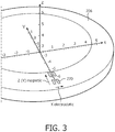
- Fig. 3 illustrates first of all the CT coordinate system, showing the conventional directions of x, y and z. It is noted, that this CT coordinate system is referenced to a patient, wherein the x-direction is lateral to the patient, the y-direction is vertical to the patient, and the z-direction is along the length of the patient.
- Fig. 3 Also shown in Fig. 3 are four deflected focal spot positions 270 on the target area of the anode 206.
- the deflection in the z-direction is produced by deflecting the electron beam in the y-direction. This causes the beam to walk up the angled track, causing the focal spot to move in the z-direction.
- the x-deflection results in an introduced parallax to improve resolution, and the z-deflection provides a double-slice capability.
- Fig. 4 shows a detailed view of the arrangement of the first deflection device, the second deflection device and a section of the anode. Furthermore, a reference coordinate system is illustrated.
- the electron emitting cathode 250 is shown with the first deflection device, here two electrostatic grids 256, mounted on either side of a cathode so that the force due to the electrostatic field produces deflection in the x-direction (indicated by arrow A).
- the electron will pass subsequently the magnetic field of the second deflection device, here electromagnetic coils 260, which is positioned to induce a deflection of the electron in y-direction (indicated by arrow B).
- each electron will impinge on the target area 270 of the anode.
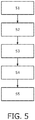
- Fig. 5 shows a flow chart with steps of a method for operating an X-ray system as described above. These steps are implemented as instructions in a computer program according to the invention. It will be understood, that the steps described with respect to the method, are major steps, wherein these major steps might be differentiated or divided into several sub steps. Furthermore, there might be also sub steps between these major steps. Therefore, a step is only mentioned, if said step is important for the understanding of the principles of the method according to the invention.
- step S1 the X-ray tube and the detector are positioned relative to the object of interest, by means of controlling the motor 103 and 113.
- step S2 the electron beam emitted by the cathode 250 in the X-ray tube 200, is deflected in x-direction, by means of controlling the first deflection device 256.
- step S3 the electron beam coming from the first deflection device 256, is deflected in y-direction, by means of controlling the second deflection device 260.
- step S4 the electron beam leaving the X-ray tube and penetrating the object of interest, impinges the detector elements of the detector.
- step S5 images are generated by the processing unit 125 on the basis of the signals received from the detector elements.
- a computer program may be stored/distributed on a suitable medium, such as an optical storage medium or solid-state medium supplied together with or as part of other hardware, but may also be distributed in other forms, such as via the Internet or other wired or wireless telecommunication systems. Any reference signs in the claims should not be construed as limiting the scope.
Landscapes
- Health & Medical Sciences (AREA)
- Life Sciences & Earth Sciences (AREA)
- Medical Informatics (AREA)
- Engineering & Computer Science (AREA)
- Radiology & Medical Imaging (AREA)
- Molecular Biology (AREA)
- Biophysics (AREA)
- Nuclear Medicine, Radiotherapy & Molecular Imaging (AREA)
- Optics & Photonics (AREA)
- Pathology (AREA)
- Physics & Mathematics (AREA)
- Biomedical Technology (AREA)
- Heart & Thoracic Surgery (AREA)
- High Energy & Nuclear Physics (AREA)
- Surgery (AREA)
- Animal Behavior & Ethology (AREA)
- General Health & Medical Sciences (AREA)
- Public Health (AREA)
- Veterinary Medicine (AREA)
- X-Ray Techniques (AREA)
- Apparatus For Radiation Diagnosis (AREA)
Applications Claiming Priority (2)
| Application Number | Priority Date | Filing Date | Title |
|---|---|---|---|
| US23350509P | 2009-08-13 | 2009-08-13 | |
| PCT/IB2010/053444 WO2011018729A1 (en) | 2009-08-13 | 2010-07-29 | X-ray tube with independent x- and z- dynamic focal spot deflection |
Publications (2)
| Publication Number | Publication Date |
|---|---|
| EP2465131A1 EP2465131A1 (en) | 2012-06-20 |
| EP2465131B1 true EP2465131B1 (en) | 2017-06-07 |
Family
ID=42931823
Family Applications (1)
| Application Number | Title | Priority Date | Filing Date |
|---|---|---|---|
| EP10742905.2A Active EP2465131B1 (en) | 2009-08-13 | 2010-07-29 | X-ray tube with independent x- and z- dynamic focal spot deflection |
Country Status (6)
| Country | Link |
|---|---|
| US (1) | US20120128122A1 (enExample) |
| EP (1) | EP2465131B1 (enExample) |
| JP (1) | JP5675808B2 (enExample) |
| CN (1) | CN102473574B (enExample) |
| BR (1) | BR112012002965A2 (enExample) |
| WO (1) | WO2011018729A1 (enExample) |
Families Citing this family (11)
| Publication number | Priority date | Publication date | Assignee | Title |
|---|---|---|---|---|
| JP6104526B2 (ja) | 2011-06-28 | 2017-03-29 | 東芝メディカルシステムズ株式会社 | X線管球及びx線ct装置 |
| JP5963217B2 (ja) | 2012-06-20 | 2016-08-03 | 株式会社日立製作所 | X線ct装置 |
| WO2014057400A1 (en) * | 2012-10-12 | 2014-04-17 | Koninklijke Philips N.V. | Radiographic imaging apparatus and method |
| US20140161233A1 (en) * | 2012-12-06 | 2014-06-12 | Bruker Axs Gmbh | X-ray apparatus with deflectable electron beam |
| WO2014115625A1 (ja) | 2013-01-28 | 2014-07-31 | 株式会社日立メディコ | X線ct装置及び画像再構成方法 |
| US9709512B2 (en) * | 2013-08-29 | 2017-07-18 | University Of Utah Research Foundation | Multilevel computed tomography for radially-shifted focal spots |
| CN106488744B (zh) * | 2014-07-28 | 2019-09-24 | 株式会社日立制作所 | X射线拍摄装置以及图像重建方法 |
| DE102015015738B4 (de) * | 2014-12-16 | 2024-05-02 | Canon Electron Tubes & Devices Co., Ltd. | Röntgenstrahlröhrenanordnung |
| US11380510B2 (en) | 2016-05-16 | 2022-07-05 | Nano-X Imaging Ltd. | X-ray tube and a controller thereof |
| WO2018214027A1 (en) * | 2017-05-23 | 2018-11-29 | Shanghai United Imaging Healthcare Co., Ltd. | Systems and methods for x-ray imaging |
| CN113223911A (zh) * | 2021-04-15 | 2021-08-06 | 上海工物高技术产业发展有限公司 | 一种双能球管 |
Citations (1)
| Publication number | Priority date | Publication date | Assignee | Title |
|---|---|---|---|---|
| JP2009158138A (ja) * | 2007-12-25 | 2009-07-16 | Toshiba Corp | X線管及びx線ct装置 |
Family Cites Families (13)
| Publication number | Priority date | Publication date | Assignee | Title |
|---|---|---|---|---|
| US4718076A (en) * | 1983-04-22 | 1988-01-05 | Kabushiki Kaisha Toshiba | X-ray imaging apparatus |
| DE3401749A1 (de) * | 1984-01-19 | 1985-08-01 | Siemens AG, 1000 Berlin und 8000 München | Roentgendiagnostikeinrichtung mit einer roentgenroehre |
| US4688241A (en) * | 1984-03-26 | 1987-08-18 | Ridge, Inc. | Microfocus X-ray system |
| JPS61153934A (ja) * | 1984-12-27 | 1986-07-12 | Toshiba Corp | 焦点位置可変形x線管 |
| US4993055A (en) * | 1988-11-23 | 1991-02-12 | Imatron, Inc. | Rotating X-ray tube with external bearings |
| JP3030069B2 (ja) * | 1990-09-13 | 2000-04-10 | イメイトロン インコーポレーテッド | X線管 |
| DE19639920C2 (de) * | 1996-09-27 | 1999-08-26 | Siemens Ag | Röntgenröhre mit variablem Fokus |
| DE19903872C2 (de) * | 1999-02-01 | 2000-11-23 | Siemens Ag | Röntgenröhre mit Springfokus zur vergrößerten Auflösung |
| DE19953613A1 (de) * | 1999-11-08 | 2001-05-17 | Siemens Ag | CT-Gerät sowie Verfahren zum Betrieb eines CT-Geräts |
| US20030095632A1 (en) * | 2001-11-20 | 2003-05-22 | Philips Medical Systems (Cleveland), Inc. | X-ray tube cathode cup structure for focal spot deflection |
| EP2271189B1 (en) * | 2003-01-06 | 2012-03-14 | Koninklijke Philips Electronics N.V. | High speed modulation of switched-focus X-ray tube |
| US6968039B2 (en) * | 2003-08-04 | 2005-11-22 | Ge Medical Systems Global Technology Co., Llc | Focal spot position adjustment system for an imaging tube |
| CN103177919B (zh) * | 2006-10-13 | 2016-12-28 | 皇家飞利浦电子股份有限公司 | 电子光学设备、x射线发射装置及产生电子束的方法 |
-
2010
- 2010-07-29 JP JP2012524311A patent/JP5675808B2/ja active Active
- 2010-07-29 WO PCT/IB2010/053444 patent/WO2011018729A1/en not_active Ceased
- 2010-07-29 BR BR112012002965A patent/BR112012002965A2/pt not_active IP Right Cessation
- 2010-07-29 EP EP10742905.2A patent/EP2465131B1/en active Active
- 2010-07-29 CN CN201080035507.0A patent/CN102473574B/zh not_active Ceased
- 2010-07-29 US US13/384,699 patent/US20120128122A1/en not_active Abandoned
Patent Citations (1)
| Publication number | Priority date | Publication date | Assignee | Title |
|---|---|---|---|---|
| JP2009158138A (ja) * | 2007-12-25 | 2009-07-16 | Toshiba Corp | X線管及びx線ct装置 |
Also Published As
| Publication number | Publication date |
|---|---|
| EP2465131A1 (en) | 2012-06-20 |
| WO2011018729A1 (en) | 2011-02-17 |
| JP2013502033A (ja) | 2013-01-17 |
| US20120128122A1 (en) | 2012-05-24 |
| BR112012002965A2 (pt) | 2019-09-24 |
| CN102473574B (zh) | 2017-12-29 |
| CN102473574A (zh) | 2012-05-23 |
| JP5675808B2 (ja) | 2015-02-25 |
Similar Documents
| Publication | Publication Date | Title |
|---|---|---|
| EP2465131B1 (en) | X-ray tube with independent x- and z- dynamic focal spot deflection | |
| CN101536134B (zh) | 具有多电子束操作单元的多焦斑x射线管 | |
| US20100074392A1 (en) | X-ray tube with multiple electron sources and common electron deflection unit | |
| EP2074642B1 (en) | X-ray emitting device and method of producing an electron beam to produce x-ray radiation in an x-ray emitting device | |
| JP7114525B2 (ja) | 異なるエネルギーレベルおよび焦点スポット位置で撮像するように構成されたコンピュータ断層撮影システムおよび方法 | |
| WO2008155695A1 (en) | Magnetic lens system for spot control in an x-ray tube | |
| EP2521490B1 (en) | X-ray tube with a combined x- and y- focal spot deflection method | |
| US20100189211A1 (en) | X-ray souce for measuring radiation | |
| EP1840935B1 (en) | X-ray inspection system with coordination between detector and multiple focal spots | |
| KR20150023617A (ko) | X-선 스캐닝 시스템용 소스 파이어링 패턴의 최적화 | |
| JP2011019802A (ja) | X線ct装置 | |
| US12274577B2 (en) | Systems and methods for computed tomography | |
| JP2013093102A (ja) | X線管装置及びx線ct装置 | |
| JP2023143444A (ja) | X線撮影装置 | |
| JP2003290207A (ja) | 多線源型x線ct装置 |
Legal Events
| Date | Code | Title | Description |
|---|---|---|---|
| PUAI | Public reference made under article 153(3) epc to a published international application that has entered the european phase |
Free format text: ORIGINAL CODE: 0009012 |
|
| 17P | Request for examination filed |
Effective date: 20120313 |
|
| AK | Designated contracting states |
Kind code of ref document: A1 Designated state(s): AL AT BE BG CH CY CZ DE DK EE ES FI FR GB GR HR HU IE IS IT LI LT LU LV MC MK MT NL NO PL PT RO SE SI SK SM TR |
|
| DAX | Request for extension of the european patent (deleted) | ||
| RAP1 | Party data changed (applicant data changed or rights of an application transferred) |
Owner name: KONINKLIJKE PHILIPS N.V. |
|
| 17Q | First examination report despatched |
Effective date: 20160520 |
|
| GRAP | Despatch of communication of intention to grant a patent |
Free format text: ORIGINAL CODE: EPIDOSNIGR1 |
|
| STAA | Information on the status of an ep patent application or granted ep patent |
Free format text: STATUS: GRANT OF PATENT IS INTENDED |
|
| RIC1 | Information provided on ipc code assigned before grant |
Ipc: A61B 6/00 20060101ALI20161213BHEP Ipc: H01J 35/14 20060101AFI20161213BHEP Ipc: H01J 35/26 20060101ALI20161213BHEP |
|
| INTG | Intention to grant announced |
Effective date: 20170104 |
|
| GRAS | Grant fee paid |
Free format text: ORIGINAL CODE: EPIDOSNIGR3 |
|
| GRAA | (expected) grant |
Free format text: ORIGINAL CODE: 0009210 |
|
| STAA | Information on the status of an ep patent application or granted ep patent |
Free format text: STATUS: THE PATENT HAS BEEN GRANTED |
|
| AK | Designated contracting states |
Kind code of ref document: B1 Designated state(s): AL AT BE BG CH CY CZ DE DK EE ES FI FR GB GR HR HU IE IS IT LI LT LU LV MC MK MT NL NO PL PT RO SE SI SK SM TR |
|
| REG | Reference to a national code |
Ref country code: GB Ref legal event code: FG4D |
|
| GRAA | (expected) grant |
Free format text: ORIGINAL CODE: 0009210 |
|
| REG | Reference to a national code |
Ref country code: CH Ref legal event code: EP Ref country code: AT Ref legal event code: REF Ref document number: 899780 Country of ref document: AT Kind code of ref document: T Effective date: 20170615 |
|
| REG | Reference to a national code |
Ref country code: IE Ref legal event code: FG4D |
|
| REG | Reference to a national code |
Ref country code: DE Ref legal event code: R096 Ref document number: 602010042835 Country of ref document: DE |
|
| REG | Reference to a national code |
Ref country code: NL Ref legal event code: MP Effective date: 20170607 |
|
| REG | Reference to a national code |
Ref country code: LT Ref legal event code: MG4D |
|
| PG25 | Lapsed in a contracting state [announced via postgrant information from national office to epo] |
Ref country code: HR Free format text: LAPSE BECAUSE OF FAILURE TO SUBMIT A TRANSLATION OF THE DESCRIPTION OR TO PAY THE FEE WITHIN THE PRESCRIBED TIME-LIMIT Effective date: 20170607 Ref country code: ES Free format text: LAPSE BECAUSE OF FAILURE TO SUBMIT A TRANSLATION OF THE DESCRIPTION OR TO PAY THE FEE WITHIN THE PRESCRIBED TIME-LIMIT Effective date: 20170607 Ref country code: NO Free format text: LAPSE BECAUSE OF FAILURE TO SUBMIT A TRANSLATION OF THE DESCRIPTION OR TO PAY THE FEE WITHIN THE PRESCRIBED TIME-LIMIT Effective date: 20170907 Ref country code: FI Free format text: LAPSE BECAUSE OF FAILURE TO SUBMIT A TRANSLATION OF THE DESCRIPTION OR TO PAY THE FEE WITHIN THE PRESCRIBED TIME-LIMIT Effective date: 20170607 Ref country code: GR Free format text: LAPSE BECAUSE OF FAILURE TO SUBMIT A TRANSLATION OF THE DESCRIPTION OR TO PAY THE FEE WITHIN THE PRESCRIBED TIME-LIMIT Effective date: 20170908 Ref country code: LT Free format text: LAPSE BECAUSE OF FAILURE TO SUBMIT A TRANSLATION OF THE DESCRIPTION OR TO PAY THE FEE WITHIN THE PRESCRIBED TIME-LIMIT Effective date: 20170607 |
|
| REG | Reference to a national code |
Ref country code: AT Ref legal event code: MK05 Ref document number: 899780 Country of ref document: AT Kind code of ref document: T Effective date: 20170607 |
|
| PG25 | Lapsed in a contracting state [announced via postgrant information from national office to epo] |
Ref country code: NL Free format text: LAPSE BECAUSE OF FAILURE TO SUBMIT A TRANSLATION OF THE DESCRIPTION OR TO PAY THE FEE WITHIN THE PRESCRIBED TIME-LIMIT Effective date: 20170607 Ref country code: BG Free format text: LAPSE BECAUSE OF FAILURE TO SUBMIT A TRANSLATION OF THE DESCRIPTION OR TO PAY THE FEE WITHIN THE PRESCRIBED TIME-LIMIT Effective date: 20170907 Ref country code: LV Free format text: LAPSE BECAUSE OF FAILURE TO SUBMIT A TRANSLATION OF THE DESCRIPTION OR TO PAY THE FEE WITHIN THE PRESCRIBED TIME-LIMIT Effective date: 20170607 Ref country code: SE Free format text: LAPSE BECAUSE OF FAILURE TO SUBMIT A TRANSLATION OF THE DESCRIPTION OR TO PAY THE FEE WITHIN THE PRESCRIBED TIME-LIMIT Effective date: 20170607 |
|
| PG25 | Lapsed in a contracting state [announced via postgrant information from national office to epo] |
Ref country code: AT Free format text: LAPSE BECAUSE OF FAILURE TO SUBMIT A TRANSLATION OF THE DESCRIPTION OR TO PAY THE FEE WITHIN THE PRESCRIBED TIME-LIMIT Effective date: 20170607 Ref country code: EE Free format text: LAPSE BECAUSE OF FAILURE TO SUBMIT A TRANSLATION OF THE DESCRIPTION OR TO PAY THE FEE WITHIN THE PRESCRIBED TIME-LIMIT Effective date: 20170607 Ref country code: RO Free format text: LAPSE BECAUSE OF FAILURE TO SUBMIT A TRANSLATION OF THE DESCRIPTION OR TO PAY THE FEE WITHIN THE PRESCRIBED TIME-LIMIT Effective date: 20170607 Ref country code: CZ Free format text: LAPSE BECAUSE OF FAILURE TO SUBMIT A TRANSLATION OF THE DESCRIPTION OR TO PAY THE FEE WITHIN THE PRESCRIBED TIME-LIMIT Effective date: 20170607 Ref country code: SK Free format text: LAPSE BECAUSE OF FAILURE TO SUBMIT A TRANSLATION OF THE DESCRIPTION OR TO PAY THE FEE WITHIN THE PRESCRIBED TIME-LIMIT Effective date: 20170607 |
|
| PG25 | Lapsed in a contracting state [announced via postgrant information from national office to epo] |
Ref country code: PL Free format text: LAPSE BECAUSE OF FAILURE TO SUBMIT A TRANSLATION OF THE DESCRIPTION OR TO PAY THE FEE WITHIN THE PRESCRIBED TIME-LIMIT Effective date: 20170607 Ref country code: SM Free format text: LAPSE BECAUSE OF FAILURE TO SUBMIT A TRANSLATION OF THE DESCRIPTION OR TO PAY THE FEE WITHIN THE PRESCRIBED TIME-LIMIT Effective date: 20170607 Ref country code: IT Free format text: LAPSE BECAUSE OF FAILURE TO SUBMIT A TRANSLATION OF THE DESCRIPTION OR TO PAY THE FEE WITHIN THE PRESCRIBED TIME-LIMIT Effective date: 20170607 Ref country code: IS Free format text: LAPSE BECAUSE OF FAILURE TO SUBMIT A TRANSLATION OF THE DESCRIPTION OR TO PAY THE FEE WITHIN THE PRESCRIBED TIME-LIMIT Effective date: 20171007 |
|
| REG | Reference to a national code |
Ref country code: CH Ref legal event code: PL |
|
| REG | Reference to a national code |
Ref country code: DE Ref legal event code: R097 Ref document number: 602010042835 Country of ref document: DE |
|
| PG25 | Lapsed in a contracting state [announced via postgrant information from national office to epo] |
Ref country code: MC Free format text: LAPSE BECAUSE OF FAILURE TO SUBMIT A TRANSLATION OF THE DESCRIPTION OR TO PAY THE FEE WITHIN THE PRESCRIBED TIME-LIMIT Effective date: 20170607 |
|
| PLBE | No opposition filed within time limit |
Free format text: ORIGINAL CODE: 0009261 |
|
| STAA | Information on the status of an ep patent application or granted ep patent |
Free format text: STATUS: NO OPPOSITION FILED WITHIN TIME LIMIT |
|
| REG | Reference to a national code |
Ref country code: FR Ref legal event code: ST Effective date: 20180330 |
|
| PG25 | Lapsed in a contracting state [announced via postgrant information from national office to epo] |
Ref country code: CH Free format text: LAPSE BECAUSE OF NON-PAYMENT OF DUE FEES Effective date: 20170731 Ref country code: LI Free format text: LAPSE BECAUSE OF NON-PAYMENT OF DUE FEES Effective date: 20170731 Ref country code: DK Free format text: LAPSE BECAUSE OF FAILURE TO SUBMIT A TRANSLATION OF THE DESCRIPTION OR TO PAY THE FEE WITHIN THE PRESCRIBED TIME-LIMIT Effective date: 20170607 |
|
| REG | Reference to a national code |
Ref country code: IE Ref legal event code: MM4A |
|
| 26N | No opposition filed |
Effective date: 20180308 |
|
| GBPC | Gb: european patent ceased through non-payment of renewal fee |
Effective date: 20170907 |
|
| PG25 | Lapsed in a contracting state [announced via postgrant information from national office to epo] |
Ref country code: SI Free format text: LAPSE BECAUSE OF FAILURE TO SUBMIT A TRANSLATION OF THE DESCRIPTION OR TO PAY THE FEE WITHIN THE PRESCRIBED TIME-LIMIT Effective date: 20170607 Ref country code: FR Free format text: LAPSE BECAUSE OF NON-PAYMENT OF DUE FEES Effective date: 20170807 |
|
| REG | Reference to a national code |
Ref country code: BE Ref legal event code: MM Effective date: 20170731 |
|
| PG25 | Lapsed in a contracting state [announced via postgrant information from national office to epo] |
Ref country code: LU Free format text: LAPSE BECAUSE OF NON-PAYMENT OF DUE FEES Effective date: 20170729 |
|
| PG25 | Lapsed in a contracting state [announced via postgrant information from national office to epo] |
Ref country code: GB Free format text: LAPSE BECAUSE OF NON-PAYMENT OF DUE FEES Effective date: 20170907 Ref country code: IE Free format text: LAPSE BECAUSE OF NON-PAYMENT OF DUE FEES Effective date: 20170729 |
|
| PG25 | Lapsed in a contracting state [announced via postgrant information from national office to epo] |
Ref country code: BE Free format text: LAPSE BECAUSE OF NON-PAYMENT OF DUE FEES Effective date: 20170731 |
|
| PG25 | Lapsed in a contracting state [announced via postgrant information from national office to epo] |
Ref country code: MT Free format text: LAPSE BECAUSE OF NON-PAYMENT OF DUE FEES Effective date: 20170729 |
|
| PG25 | Lapsed in a contracting state [announced via postgrant information from national office to epo] |
Ref country code: HU Free format text: LAPSE BECAUSE OF FAILURE TO SUBMIT A TRANSLATION OF THE DESCRIPTION OR TO PAY THE FEE WITHIN THE PRESCRIBED TIME-LIMIT; INVALID AB INITIO Effective date: 20100729 |
|
| PG25 | Lapsed in a contracting state [announced via postgrant information from national office to epo] |
Ref country code: CY Free format text: LAPSE BECAUSE OF NON-PAYMENT OF DUE FEES Effective date: 20170607 |
|
| PG25 | Lapsed in a contracting state [announced via postgrant information from national office to epo] |
Ref country code: MK Free format text: LAPSE BECAUSE OF FAILURE TO SUBMIT A TRANSLATION OF THE DESCRIPTION OR TO PAY THE FEE WITHIN THE PRESCRIBED TIME-LIMIT Effective date: 20170607 |
|
| PG25 | Lapsed in a contracting state [announced via postgrant information from national office to epo] |
Ref country code: TR Free format text: LAPSE BECAUSE OF FAILURE TO SUBMIT A TRANSLATION OF THE DESCRIPTION OR TO PAY THE FEE WITHIN THE PRESCRIBED TIME-LIMIT Effective date: 20170607 |
|
| PG25 | Lapsed in a contracting state [announced via postgrant information from national office to epo] |
Ref country code: PT Free format text: LAPSE BECAUSE OF FAILURE TO SUBMIT A TRANSLATION OF THE DESCRIPTION OR TO PAY THE FEE WITHIN THE PRESCRIBED TIME-LIMIT Effective date: 20170607 |
|
| PG25 | Lapsed in a contracting state [announced via postgrant information from national office to epo] |
Ref country code: AL Free format text: LAPSE BECAUSE OF FAILURE TO SUBMIT A TRANSLATION OF THE DESCRIPTION OR TO PAY THE FEE WITHIN THE PRESCRIBED TIME-LIMIT Effective date: 20170607 |
|
| REG | Reference to a national code |
Ref country code: DE Ref legal event code: R084 Ref document number: 602010042835 Country of ref document: DE |
|
| PGFP | Annual fee paid to national office [announced via postgrant information from national office to epo] |
Ref country code: DE Payment date: 20250728 Year of fee payment: 16 |