EP2464447B1 - Vorrichtung zum eintrag von gas in flüssigkeiten - Google Patents
Vorrichtung zum eintrag von gas in flüssigkeiten Download PDFInfo
- Publication number
- EP2464447B1 EP2464447B1 EP10755116.0A EP10755116A EP2464447B1 EP 2464447 B1 EP2464447 B1 EP 2464447B1 EP 10755116 A EP10755116 A EP 10755116A EP 2464447 B1 EP2464447 B1 EP 2464447B1
- Authority
- EP
- European Patent Office
- Prior art keywords
- gas
- line
- ozone
- liquid
- chamber
- Prior art date
- Legal status (The legal status is an assumption and is not a legal conclusion. Google has not performed a legal analysis and makes no representation as to the accuracy of the status listed.)
- Active
Links
Images
Classifications
-
- B—PERFORMING OPERATIONS; TRANSPORTING
- B01—PHYSICAL OR CHEMICAL PROCESSES OR APPARATUS IN GENERAL
- B01F—MIXING, e.g. DISSOLVING, EMULSIFYING OR DISPERSING
- B01F23/00—Mixing according to the phases to be mixed, e.g. dispersing or emulsifying
- B01F23/20—Mixing gases with liquids
- B01F23/23—Mixing gases with liquids by introducing gases into liquid media, e.g. for producing aerated liquids
- B01F23/232—Mixing gases with liquids by introducing gases into liquid media, e.g. for producing aerated liquids using flow-mixing means for introducing the gases, e.g. baffles
-
- B—PERFORMING OPERATIONS; TRANSPORTING
- B01—PHYSICAL OR CHEMICAL PROCESSES OR APPARATUS IN GENERAL
- B01F—MIXING, e.g. DISSOLVING, EMULSIFYING OR DISPERSING
- B01F25/00—Flow mixers; Mixers for falling materials, e.g. solid particles
- B01F25/30—Injector mixers
- B01F25/32—Injector mixers wherein the additional components are added in a by-pass of the main flow
-
- B—PERFORMING OPERATIONS; TRANSPORTING
- B01—PHYSICAL OR CHEMICAL PROCESSES OR APPARATUS IN GENERAL
- B01F—MIXING, e.g. DISSOLVING, EMULSIFYING OR DISPERSING
- B01F25/00—Flow mixers; Mixers for falling materials, e.g. solid particles
- B01F25/50—Circulation mixers, e.g. wherein at least part of the mixture is discharged from and reintroduced into a receptacle
- B01F25/53—Circulation mixers, e.g. wherein at least part of the mixture is discharged from and reintroduced into a receptacle in which the mixture is discharged from and reintroduced into a receptacle through a recirculation tube, into which an additional component is introduced
-
- C—CHEMISTRY; METALLURGY
- C02—TREATMENT OF WATER, WASTE WATER, SEWAGE, OR SLUDGE
- C02F—TREATMENT OF WATER, WASTE WATER, SEWAGE, OR SLUDGE
- C02F9/00—Multistage treatment of water, waste water or sewage
- C02F9/20—Portable or detachable small-scale multistage treatment devices, e.g. point of use or laboratory water purification systems
-
- B—PERFORMING OPERATIONS; TRANSPORTING
- B01—PHYSICAL OR CHEMICAL PROCESSES OR APPARATUS IN GENERAL
- B01F—MIXING, e.g. DISSOLVING, EMULSIFYING OR DISPERSING
- B01F25/00—Flow mixers; Mixers for falling materials, e.g. solid particles
- B01F2025/91—Direction of flow or arrangement of feed and discharge openings
- B01F2025/918—Counter current flow, i.e. flows moving in opposite direction and colliding
-
- C—CHEMISTRY; METALLURGY
- C02—TREATMENT OF WATER, WASTE WATER, SEWAGE, OR SLUDGE
- C02F—TREATMENT OF WATER, WASTE WATER, SEWAGE, OR SLUDGE
- C02F1/00—Treatment of water, waste water, or sewage
- C02F1/72—Treatment of water, waste water, or sewage by oxidation
- C02F1/722—Oxidation by peroxides
-
- C—CHEMISTRY; METALLURGY
- C02—TREATMENT OF WATER, WASTE WATER, SEWAGE, OR SLUDGE
- C02F—TREATMENT OF WATER, WASTE WATER, SEWAGE, OR SLUDGE
- C02F1/00—Treatment of water, waste water, or sewage
- C02F1/72—Treatment of water, waste water, or sewage by oxidation
- C02F1/76—Treatment of water, waste water, or sewage by oxidation with halogens or compounds of halogens
-
- C—CHEMISTRY; METALLURGY
- C02—TREATMENT OF WATER, WASTE WATER, SEWAGE, OR SLUDGE
- C02F—TREATMENT OF WATER, WASTE WATER, SEWAGE, OR SLUDGE
- C02F1/00—Treatment of water, waste water, or sewage
- C02F1/72—Treatment of water, waste water, or sewage by oxidation
- C02F1/78—Treatment of water, waste water, or sewage by oxidation with ozone
-
- C—CHEMISTRY; METALLURGY
- C02—TREATMENT OF WATER, WASTE WATER, SEWAGE, OR SLUDGE
- C02F—TREATMENT OF WATER, WASTE WATER, SEWAGE, OR SLUDGE
- C02F2103/00—Nature of the water, waste water, sewage or sludge to be treated
- C02F2103/02—Non-contaminated water, e.g. for industrial water supply
- C02F2103/026—Treating water for medical or cosmetic purposes
-
- C—CHEMISTRY; METALLURGY
- C02—TREATMENT OF WATER, WASTE WATER, SEWAGE, OR SLUDGE
- C02F—TREATMENT OF WATER, WASTE WATER, SEWAGE, OR SLUDGE
- C02F2209/00—Controlling or monitoring parameters in water treatment
- C02F2209/02—Temperature
-
- C—CHEMISTRY; METALLURGY
- C02—TREATMENT OF WATER, WASTE WATER, SEWAGE, OR SLUDGE
- C02F—TREATMENT OF WATER, WASTE WATER, SEWAGE, OR SLUDGE
- C02F2209/00—Controlling or monitoring parameters in water treatment
- C02F2209/23—O3
-
- C—CHEMISTRY; METALLURGY
- C02—TREATMENT OF WATER, WASTE WATER, SEWAGE, OR SLUDGE
- C02F—TREATMENT OF WATER, WASTE WATER, SEWAGE, OR SLUDGE
- C02F2209/00—Controlling or monitoring parameters in water treatment
- C02F2209/40—Liquid flow rate
-
- C—CHEMISTRY; METALLURGY
- C02—TREATMENT OF WATER, WASTE WATER, SEWAGE, OR SLUDGE
- C02F—TREATMENT OF WATER, WASTE WATER, SEWAGE, OR SLUDGE
- C02F2301/00—General aspects of water treatment
- C02F2301/04—Flow arrangements
- C02F2301/043—Treatment of partial or bypass streams
-
- Y—GENERAL TAGGING OF NEW TECHNOLOGICAL DEVELOPMENTS; GENERAL TAGGING OF CROSS-SECTIONAL TECHNOLOGIES SPANNING OVER SEVERAL SECTIONS OF THE IPC; TECHNICAL SUBJECTS COVERED BY FORMER USPC CROSS-REFERENCE ART COLLECTIONS [XRACs] AND DIGESTS
- Y10—TECHNICAL SUBJECTS COVERED BY FORMER USPC
- Y10T—TECHNICAL SUBJECTS COVERED BY FORMER US CLASSIFICATION
- Y10T137/00—Fluid handling
- Y10T137/0318—Processes
Definitions
- the present invention relates to a device for introducing gas into liquids.
- biofilms can be created on pipeline walls.
- the extracellular polymeric substances serve, among other things, the external protection against pH fluctuations, salts, hydraulic stress, toxic heavy metals, antibiotics and immune defense mechanisms.
- the matrix structure leads to enormously high resistance of the relevant life forms, which for these reasons are sometimes up to a thousand times more resistant to antimicrobial agents than the individual organisms ( Gilbert, P., Das, J. and Foley, I.
- the problematic biofilm bacteria include in particular Pseudomonas aeroginosa, Legionella pneumophila, Acinetobacter, atypical mycobacteria and Serratia.
- the Pseudomonas aeruginosa infections are due to contaminated tap water ( Reuter, S., Sigge, A., Reuter, U. et al. (2002) Endemic transmission pathways of Pseudomonas aeroginosa, Hyg Mikrobiol 6: 6-12 ). Therefore, such infections are a significant problem, especially in intensive care units, dialysis centers or surgical departments.
- biofilms are a significant hazard.
- filters, ion exchangers or membranes promote the development of such biofilms.
- Additional factors that favor the multiplication of bacteria are, for. B. dead spaces in water supply systems, low or no flow rates and the use of bicarbonate concentrate, which is used for the preparation of dialysis fluids.
- Suitable disinfectants include ozone. This gas has found use, for example, in the food industry, in drinking and wastewater treatment and in dental treatment. Corresponding plants for the use of ozone are for example in the DE 10061890 A1 . DE 1016365 A1 . DE 29806719 U1 . DE 3225674 A1 . DE 202008001211 U1 and the EP 0577475 A1 described. Ozonmaschinesanlagen in various configurations include the US 4,252,654 A , of the CH 365342 A , of the DE 3737424 A1 , of the DE 3830909 A1 and the US 2006/0237557 known.
- the object of the present invention has been made to provide a device for the entry of gas in liquids, which is compact and versatile can be used.
- injectors operating according to the Venturi principle are dispensed with.
- the invention operates independently of flow and pressure fluctuations.
- This method can also be referred to as an active concentrator.
- the device should be used in disinfection and Sanitmaschinesvon use, especially in thermo-stable systems. Especially in the field of medicine, especially in the field of dialysis devices, the device should be used.
- the introduction of the gaseous oxidizing agent can preferably be achieved by a device for introducing gas into liquids according to claim 1.
- the device for introducing gas into liquid can be operated in countercurrent or direct current. That is, gas and liquid can be introduced from the same side in the flow tube, or introduced in countercurrent to each other.
- the return of the subset of the gas liquid mixture contains feed modules for enrichment with gaseous oxidant, eg ozone.
- the feed modules serve as entry systems and consist of a cylindrical bore in the configuration of a tapered cone.
- the beginning of the return line connects, which is chosen in its dimensions so that a vortex is created by increasing the flow velocity in the interior of the cylindrical bore. This vortex breaks up the incoming bubbles (macro bubbles become microbubbles).
- vortex formation accelerates breakage of the bubbles at the generator.
- the conical jacket preferably inclines at an angle of from 10 ° to 80 °, particularly preferably from 45 ° to 60 ° in relation to the vertically vertically oriented wall of the chamber.
- the diameter of the adjoining channel to the return line is preferably 1 to 12 mm, more preferably 2 to 9 mm. Preferred is an embodiment in which the diameter of the Return channel 10 to 40%, preferably 15 to 30% of the cylinder bore of the chamber diameter.
- a downstream positive displacement pump e.g. a gear pump
- the oxidizing agent preferably ozone
- the positive displacement pump is connected downstream of the cylindrical bore in such a way that the system works as an absorber.
- Any number of these modules can be connected in series.
- the number of modules is suitable for optimizing the amount of gas introduced for the respective application.
- the repeated recycling leads to an optimal utilization and concentration of the supplied gas in the liquid.
- gas and liquid in the flow tube can also be made of several parallel gas inlet modules.
- DC and reverse circuits There are any combinations for DC and reverse circuits conceivable. For example, one device may be cocurrent and several others may be run in countercurrent.
- the entry system thus works as a concentrator. This has the task of increasing the concentration of oxidizing agent, for example ozone in the water.
- the enriched with gaseous oxidant water is repeatedly passed through the entry system.
- the water is thereby enriched again with the oxidizing agent.
- the reactor used is a cavity which is incorporated in the block or executed individually.
- the concentrator can be driven in the DC or countercurrent principle - as already mentioned above.
- the reaction spaces or cavities required for operation can be constructed, for example, as holes in a block or discretely.
- the entry system and the downstream Liquid systems may possibly also include degassing devices in addition to the described devices.
- excess oxidant such as ozone, can be removed or recycled.
- the device according to the invention can be used in any system. It can be used for a flow gas enrichment. In this case, it is possible that an enrichment of ozone in liquids is carried out as flow ozonization. Likewise, however, a method in batch mode is possible, ie that the ozonization of liquids is carried out in batch mode, wherein volume is removed from a working vessel and a repeated ozonization of a liquid is achieved by repeated circulation through the flow tube or entry system according to the invention , This is usually done with ozone concentrations from about 20 ppb and many times more.
- An advantage of the system according to the invention is that it is also possible to work under excess pressure. Typically, working in dialysis equipment up to 6 bar operating pressure. Preferably, the system is designed for pressures of 0-15 bar, more preferably for pressures of 0-8 bar. However, higher pressures are also possible constructively with the gas introduction system.
- Ozone offers a number of advantages over other oxidants and conventional disinfectants.
- the biofilm is safely degraded or the germ count significantly reduced and there are no chemical Residues back; because ozone breaks down into oxygen.
- the formation of a new biofilm is suppressed.
- only the lowest concentrations are needed.
- the use of ozone allows you to work without heat. Thus, effective cold disinfection and sanitization can be performed.
- ozone it is particularly preferred according to the invention for ozone to be produced directly in the system in a special generation device.
- all methods known to those skilled in the art come into consideration.
- the ozone can be produced from oxygen with the addition of energy by means of so-called silent electrical discharges.
- Ozone formation takes place here by recombination of an oxygen molecule with an oxygen atom. So there must be a cleavage of an oxygen molecule by electrical energy. This is achieved in a gas space between two electrodes, which are separated by a dielectric. Alternating current and a high voltage field are applied to the electrodes. In most cases, the ozone production units are positioned as glass or ceramic tubes in stainless steel tubes, so that the narrowest possible annular discharge gap is formed. A corresponding number of these ozone production modules can then be used for the production of ozone quantities of a few grams / hour to many kilograms / hour. As operating gas either oxygen or air are used.
- UV light it is also possible to produce ozone from the operating gas (oxygen or air) by using UV light, ie the electrical splitting of oxygen can also be effected by radiation energy.
- UV lamps having radiation wavelengths of about 185 nm. At this wavelength, molecular oxygen absorbs energy and is split into atoms. The recombination of the atoms then leads to the ozone molecule.
- the UV ozone generators usually consist of an irradiation reactor with built-in lamp, where the oxygen-containing operating gas flows past and is converted into ozone. These devices are preferably used for small ozone amounts of a few grams / hour.
- An alternative is the preparation of liquid containing oxygen, especially water.
- energy for example, electrical energy
- the ozone is produced.
- ozone is produced from the oxygen of the water molecule ( DE000004222732C2 . EP0000000068522A1 ).
- a DC voltage source generates the required electrolysis current, which leads to ozone gas generation at the anode.
- the process in question can be used primarily for small ozone quantities of a few grams / hour.
- electrolytic ozone generators in demineralised water after switching off the voltage, apply a suitable protective voltage so that the electrodes of the cell are not damaged.
- the system described has significant advantages over the prior art. It is adaptable as a compact central unit for each plant and can be used for cold disinfection and penetration. Due to the compact design with the outer dimensions of 35-45 x 45-65 x 70-90 cm, preferably of 38-42 x 48-60 x 75-85 cm, more preferably of 40x50x80cm this system is particularly suitable for mobile use , Particularly noteworthy is the structure, a closed system that has no connection to the atmosphere via any container or tank. This design avoids the disadvantages of the venturi system that collapses during pressure changes or flow interruptions. The system allows under Inclusion of suitable couplings and valves Totally free complete disinfection and sanitisation by means of decentralized branch line perfusion without active end users.
- the regular disinfection is highly effective and cost-effective, since no ring or transfer module conversion is necessary and almost no or only low follow-up costs arise in comparison to hot disinfection. Furthermore, biofilm formation is completely or largely prevented and no chemical residues remain. The ozone breaks down into non-toxic oxygen. On the other hand, even the smallest ozone concentrations are microbiologically very effective.
- the device according to the invention can also be used inter alia because of its compact design for periodic disinfection of water treatment systems such as ion exchangers for softening and reverse osmosis. Outside of dialysis, it can be used in other areas of medical and laboratory technology as well as in drinking water treatment and the preservation of liquids. Likewise, use in laboratory water supplies, in hospitals and care facilities, in the beverage and beverage Automatentechnk conceivable. Further areas of application include fish and livestock husbandry, as well as hot water, heating and air conditioning, e.g. in hotels, sauna, wellness and swimming pools. Also possible are applications in process and wastewater treatment.
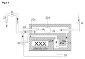
- FIG. 1 the ozone production and injection system according to the invention is shown in detail.
- line 18 to be ozonated water is introduced.
- line 19 the suction of liquid for ozone introduction into the chamber 25 a by means of a positive displacement pump 26 and return via the return line 20 into the flow tube 22.
- the chambers 25 a, b, c and d are provided with an ozone introduction supply line 25.
- the return line 20 terminates in the flow tube 22 with the spout 21. Das Enriched ozone-liquid mixture leaves the flow tube 22 via the outflow 23.
- valve 24 can be switched so that the liquid flow is throttled from 18 to 23 and / or stopped, first the liquid gas mixture is circulated by means of pump 26 until a optimal enrichment has occurred.
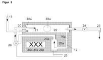
- a conical nozzle 25 e for introducing ozone into the sucked liquid is arranged in the ozonization chamber 25 a.
- further chambers 25b, 25c and 25d may be arranged.
- temperature and gas bubbles, measuring, control and regulating devices 19a, 20a, 22a may be arranged.
- the lines 18 and 20 introduce liquid and ozone in countercurrent to the flow tube 22 a.
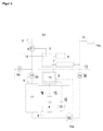
- the FIG. 3 provides the integration of the invention according to FIG. 1 or 2 the example of a disinfection of a loop with connected end user (15a) of a dialysis device.
- the end user 15a is connected via the branch line 15 with the return line of the loop 12.
- the reverse osmosis control 8 can be switched on or off.
- the ozone / water mixture coming from the ozone generating and injection system 4 is introduced into the working vessel 17.
- the ozone generator is upstream of the circulation pump 10 on the suction side.
- the control takes place by means of the device 2, which has a touchscreen 14 in the example.
- the ozone concentration can be measured via the device 5 in the inner circuit 1 and in the outer circuit 3.
- the circulation pump 10 the ozone in the inner circuit 1 is guided and enriched the water with ozone.
- the working container 17 is subjected to disinfection.
- the excess ozone is removed via the degassing device 6.
- the ozone concentration is at least 30 ppb in the Work bowl 17 kept constant for about 10 to 15 minutes.
- the outer circuit 3 can be coupled and operated by means of pressure booster pumps 10a. These are the dialysis ring lines 12, as well as the end consumers 15a which are connected via the stub line (s) 15.
- the adjustable reaction time begins. The ozone concentration in the outer circuit 3 and in the inner circuit 1 is measured and recorded via the ozone measuring device 5.
- the system After completion of the disinfection, the system is flushed with the permeate of reverse osmosis through the channel valve 9a.
- the ozone concentration in the return of the loop 12 is measured.
- an adjustable rinsing time at which the line was rinsed out with a multiple of its contents and the ozone concentration in the ring line 12 (return) is less than 10 ppb, the rinse is stopped and the system is released again for dialysis.
- the disinfection stops and the system is flushed as described.
- the ring line is usually available for dialysis operation again after 30 minutes at the latest.
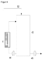
- FIG. 4 provides the integration of the invention according to FIG. 1 and FIG. 2
- medium from the batch container 43 is circulated by means of a pump 52 via the ozone generating and feeding device 4 until the desired concentration is reached in the batch container 43.
- the thus enriched with ozone medium is then pumped if necessary by means of the pump 45 to the consumer or for further use.
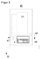
- FIG. 5 adjusts the integration according to FIG. 1 or 2
- the filling of the beverage preparation unit 51 takes place via valve block 1 (47).
- the valve block 2 three-way valve 48
- the supply to the ozone generating and recording unit 4 is controlled as required or to the removal point 49 of the beverage machine 46.
- the beverage machine can be emptied.
Landscapes
- Chemical & Material Sciences (AREA)
- Chemical Kinetics & Catalysis (AREA)
- Hydrology & Water Resources (AREA)
- Health & Medical Sciences (AREA)
- Engineering & Computer Science (AREA)
- Environmental & Geological Engineering (AREA)
- Water Supply & Treatment (AREA)
- Life Sciences & Earth Sciences (AREA)
- Organic Chemistry (AREA)
- Clinical Laboratory Science (AREA)
- Treatment Of Water By Oxidation Or Reduction (AREA)
- Apparatus For Disinfection Or Sterilisation (AREA)
- Sampling And Sample Adjustment (AREA)
- Accessories For Mixers (AREA)
Applications Claiming Priority (2)
| Application Number | Priority Date | Filing Date | Title |
|---|---|---|---|
| DE102009026376A DE102009026376A1 (de) | 2009-08-14 | 2009-08-14 | Vorrichtung zum Eintrag von Gas in Flüssigkeiten |
| PCT/EP2010/061908 WO2011018529A1 (de) | 2009-08-14 | 2010-08-16 | Vorrichtung zum eintrag von gas in flüssigkeiten |
Publications (2)
| Publication Number | Publication Date |
|---|---|
| EP2464447A1 EP2464447A1 (de) | 2012-06-20 |
| EP2464447B1 true EP2464447B1 (de) | 2016-09-14 |
Family
ID=43234285
Family Applications (1)
| Application Number | Title | Priority Date | Filing Date |
|---|---|---|---|
| EP10755116.0A Active EP2464447B1 (de) | 2009-08-14 | 2010-08-16 | Vorrichtung zum eintrag von gas in flüssigkeiten |
Country Status (6)
| Country | Link |
|---|---|
| US (1) | US20120138155A1 (enExample) |
| EP (1) | EP2464447B1 (enExample) |
| AU (1) | AU2010283724B2 (enExample) |
| DE (1) | DE102009026376A1 (enExample) |
| IN (2) | IN2012DN01262A (enExample) |
| WO (1) | WO2011018529A1 (enExample) |
Families Citing this family (4)
| Publication number | Priority date | Publication date | Assignee | Title |
|---|---|---|---|---|
| BR112014013734A2 (pt) | 2011-12-06 | 2017-06-13 | Masco Corp | distribuição de ozônio em uma torneira |
| DE102012103871B4 (de) * | 2012-05-03 | 2015-03-26 | Klaus Nonnenmacher | Vorrichtung und Verfahren zur Ozonierung von Wasser |
| CN108463437B (zh) | 2015-12-21 | 2022-07-08 | 德尔塔阀门公司 | 包括消毒装置的流体输送系统 |
| MX2020000303A (es) | 2017-07-10 | 2020-07-22 | Flow Control LLC | Grifo dispensador con infusión integral. |
Family Cites Families (31)
| Publication number | Priority date | Publication date | Assignee | Title |
|---|---|---|---|---|
| US2606150A (en) * | 1948-04-08 | 1952-08-05 | Air Reduction | Dispersion of gaseous treating agents in liquids |
| BE572789A (enExample) * | 1957-11-07 | |||
| FR1353214A (fr) * | 1962-03-10 | 1964-05-29 | August Klueber | Procédé d'ozonisation d'eau et dispositif pour sa mise en oeuvre |
| DE2556328C2 (de) * | 1975-12-13 | 1982-06-03 | Hoechst Ag | Verfahren zur Wasserbehandlung |
| DE2827151C2 (de) * | 1978-06-21 | 1982-05-06 | Messer Griesheim Gmbh, 6000 Frankfurt | Verfahren zur Wasserbehandlung mittels Ozon |
| EP0068522B1 (de) | 1981-05-11 | 1984-10-24 | BBC Aktiengesellschaft Brown, Boveri & Cie. | Verfahren und Vorrichtung zur synthetischen Herstellung von Ozon durch Elektrolyse und deren Verwendung |
| PL129859B1 (en) | 1981-07-29 | 1984-06-30 | Inst Chemii Przemyslowej | Method of contacting gaseous and liquid media and packing therefor |
| DE3220451C2 (de) | 1982-05-29 | 1986-06-26 | Karl 6840 Lampertheim Heess | Verfahren und Vorrichtung zum Sterilisieren von Getränkebehältern mittels eines Wasser-Ozon-Gemisches |
| DE3225674A1 (de) | 1982-07-09 | 1984-01-12 | Fichtel & Sachs Ag, 8720 Schweinfurt | Verfahren und vorrichtung zum feststellen der erschoepfung der adsorptionsfuellung eines adsorptionsfilters zum entzug von chlor aus trinkwasser |
| DE3737424A1 (de) | 1986-12-26 | 1988-07-07 | Mitsubishi Electric Corp | Wasser-ozonisierung-system |
| DE3830909A1 (de) | 1988-09-10 | 1990-03-22 | Astra Meditec Ab | Krampfadersonde |
| DE3830999A1 (de) * | 1988-09-12 | 1990-03-15 | Friedrich Tiefenbrunner | Badewasseraufbereitungsanlage zur ozonung von badewasser |
| DE3913334A1 (de) | 1989-04-22 | 1990-10-25 | Caldyn Apparatebau Gmbh | Vorrichtung fuer die zerstaeubung von fluessigkeit oder fuer die zerteilung von gas in kleine blasen |
| NL9100815A (nl) | 1991-05-10 | 1992-12-01 | Kema Nv | Werkwijze voor het vervaardigen van een ionomeer. |
| FR2692882B1 (fr) | 1992-06-29 | 1994-10-07 | Trailigaz | Procédé de traitement, notamment d'eaux à potabiliser, à l'ozone. Installation pour la mise en Óoeuvre du procédé. |
| DE4227732C2 (de) | 1992-08-21 | 1996-05-02 | Fischer Labor Und Verfahrenste | Elektrolysezelle, insbesondere zur Erzeugung von Ozon, mit einer den Anoden- und Kathodenraum voneinander trennenden Feststoffelektrolytmembran |
| US6146524A (en) * | 1997-09-15 | 2000-11-14 | Story; Craig W. | Multi-stage ozone injection water treatment system |
| US6382601B1 (en) * | 1997-12-30 | 2002-05-07 | Hirofumi Ohnari | Swirling fine-bubble generator |
| DE29806719U1 (de) | 1998-04-06 | 1998-08-20 | Glibitski, Marks, Prof. Dr., 12353 Berlin | Ultraviolett- Ozon- Trinkwasseraufbereitungsanlage |
| DE10016365B4 (de) | 2000-04-04 | 2008-12-18 | Thomas Steinle | Verfahren zur Trinkwasseraufbereitung |
| DE10061890C2 (de) | 2000-12-12 | 2002-11-21 | Deutsch Zentr Luft & Raumfahrt | Vorrichtung zur Aufbereitung von Wasser, insbesondere zur Gewinnung von Trinkwasser, durch Behandlung mit Ozon |
| WO2002102723A1 (en) * | 2001-06-15 | 2002-12-27 | Vrm Enterprises Pty Ltd | Method and apparatus for the treatment of water |
| KR20030016875A (ko) * | 2001-08-22 | 2003-03-03 | 최영규 | 측류 오존수에 의한 수처리 장치 |
| DE10163659A1 (de) | 2001-12-21 | 2003-07-03 | Gummi Jaeger Kg Gmbh & Cie | Vorrichtung zum Belüften von Wasser |
| DE10246452B4 (de) | 2002-10-04 | 2007-12-27 | Dinotec Gmbh Wassertechnologie Und Schwimmbadtechnik | Reaktionsgefäß zur Aufbereitung von Wasser mit Ozon |
| EP1491495A1 (fr) | 2003-06-26 | 2004-12-29 | Antonino Patti | Générateur et microdoseur électronique d'ozone dans l'eau |
| DE10340024B3 (de) | 2003-08-28 | 2005-04-14 | Thomas Funk | Vorrichtung zum Anreichern einer Flüssigkeit mit wenigstens einem Gas |
| CA2485873A1 (en) * | 2004-10-22 | 2006-04-22 | Peter Douglas Jack | Apparatus and method for blending or infusing one fluid into another fluid |
| US7377407B2 (en) * | 2005-04-19 | 2008-05-27 | Entrepure Industries, Inc. | Modular water vending system and dispenser |
| EP2142479A1 (en) * | 2007-04-19 | 2010-01-13 | Applied Process Technology, Inc. | Process and apparatus for water decontamination |
| DE202008001211U1 (de) | 2008-01-25 | 2009-01-29 | Weimer, Jürgen | Auslauf zur Aufnahme einer Ozonmicrozelle zur Verhinderung einer Rückverkeimung bei der Abgabe von Trinkwasser |
-
2009
- 2009-08-14 DE DE102009026376A patent/DE102009026376A1/de not_active Withdrawn
-
2010
- 2010-08-16 AU AU2010283724A patent/AU2010283724B2/en active Active
- 2010-08-16 IN IN1262DEN2012 patent/IN2012DN01262A/en unknown
- 2010-08-16 US US13/390,156 patent/US20120138155A1/en not_active Abandoned
- 2010-08-16 EP EP10755116.0A patent/EP2464447B1/de active Active
- 2010-08-16 IN IN1263DEN2012 patent/IN2012DN01263A/en unknown
- 2010-08-16 WO PCT/EP2010/061908 patent/WO2011018529A1/de not_active Ceased
Also Published As
| Publication number | Publication date |
|---|---|
| EP2464447A1 (de) | 2012-06-20 |
| DE102009026376A1 (de) | 2011-02-24 |
| US20120138155A1 (en) | 2012-06-07 |
| AU2010283724B2 (en) | 2016-06-23 |
| AU2010283724A1 (en) | 2012-04-05 |
| WO2011018529A1 (de) | 2011-02-17 |
| IN2012DN01263A (enExample) | 2015-05-15 |
| IN2012DN01262A (enExample) | 2015-05-15 |
Similar Documents
| Publication | Publication Date | Title |
|---|---|---|
| EP2464396B1 (de) | ANKOPPLUNGS- UND UMSCHALTEINHEIT FÜR LEiTUNGEN ZUM TRANSPORT VON FLUIDEN | |
| EP2423169B1 (de) | Vorrichtung zur Erzeugung von Reinstwasser mit Umkehrosmose und Enthärter | |
| EP2569028B1 (de) | System zur herstellung von reinstwasser in der dialyse | |
| EP2464447B1 (de) | Vorrichtung zum eintrag von gas in flüssigkeiten | |
| DE102006007931A1 (de) | Verfahren zur Herstellung eines Desinfektionsmittels durch elektrochemische Aktivierung (ECA) von Wasser und Verfahren zur Desinfektion von Wasser mittels eines solchen Desinfektionsmittels | |
| DE102009026377A1 (de) | Anlage zur Desinfektion und Sanitisierung | |
| DE102008004663B4 (de) | Verfahren zur elektrochemischen Hygienisierung und Keimminderung von biologisch gereinigtem Abwasser, insbesondere häuslichem Abwasser, und von Abwasserteilströmen und Vorrichtung dazu | |
| DE4430587A1 (de) | Verfahren und Vorrichtung zur Keimreduzierung von Wasser und wäßrigen Lösungen | |
| US20090071883A1 (en) | Electrolytic system for obtaining a disinfectant | |
| EP2078174B1 (de) | Wasseraufbereitungssystem | |
| DE3121337A1 (de) | Filteranlage | |
| EP1380543A1 (de) | Wasseraufbereitungsanlage zur Erzeugung von trinkbarem Wasser | |
| DE102006037322B4 (de) | Transportable Eintauch-Elektrolysezelle | |
| DE202009018551U1 (de) | Anlage zur Desinfektion und Sanitisierung | |
| DE19926159B4 (de) | Mini-Elektrolysezelle | |
| DE102011012137B4 (de) | Verfahren und Vorrichtung zur Aufbereitung von Badewasser | |
| DE102018009448B4 (de) | Verfahren zum Betrieb einer transportablen Eintauch-Elektrolysezelle und Eintauch-Elektrolysezelle | |
| CN217230959U (zh) | 一种次氯酸水消毒液制造机 | |
| DE2756400A1 (de) | Verfahren zum keimfreimachen von fluessigkeiten, insbesondere schwimmbadwasser, mittels uv-strahlung und einleiten von ozon sowie einrichtung zur durchfuehrung des verfahrens | |
| EP1547977A1 (de) | Verfahren zur Aufbereitung von Abwasser | |
| DE102009051489A1 (de) | Verfahren zum Betrieb eines Wasseraufbereitungssystems sowie zur Durchführung des Verfahrens geeignetes Wasseraufbereitungssystem | |
| DE102004015381B4 (de) | Desinfektion von Nutzgas-Leitungssytemen | |
| AT399863B (de) | Verfahren zur reduzierung von mikroorganismen und/oder phathogenen keimen in wässern, vorrichtung zu dessen durchführung und verwendung der vorrichtung | |
| EP3434649A1 (de) | Vorrichtung und verfahren zum abbau von persistenten organischen verunreinigungen aus abwasser | |
| DE202007009705U1 (de) | Anlage zur Aufbereitung von desinfiziertem Wasser |
Legal Events
| Date | Code | Title | Description |
|---|---|---|---|
| PUAI | Public reference made under article 153(3) epc to a published international application that has entered the european phase |
Free format text: ORIGINAL CODE: 0009012 |
|
| 17P | Request for examination filed |
Effective date: 20120228 |
|
| AK | Designated contracting states |
Kind code of ref document: A1 Designated state(s): AL AT BE BG CH CY CZ DE DK EE ES FI FR GB GR HR HU IE IS IT LI LT LU LV MC MK MT NL NO PL PT RO SE SI SK SM TR |
|
| DAX | Request for extension of the european patent (deleted) | ||
| 17Q | First examination report despatched |
Effective date: 20150219 |
|
| GRAP | Despatch of communication of intention to grant a patent |
Free format text: ORIGINAL CODE: EPIDOSNIGR1 |
|
| INTG | Intention to grant announced |
Effective date: 20160426 |
|
| GRAS | Grant fee paid |
Free format text: ORIGINAL CODE: EPIDOSNIGR3 |
|
| GRAA | (expected) grant |
Free format text: ORIGINAL CODE: 0009210 |
|
| AK | Designated contracting states |
Kind code of ref document: B1 Designated state(s): AL AT BE BG CH CY CZ DE DK EE ES FI FR GB GR HR HU IE IS IT LI LT LU LV MC MK MT NL NO PL PT RO SE SI SK SM TR |
|
| REG | Reference to a national code |
Ref country code: GB Ref legal event code: FG4D Free format text: NOT ENGLISH |
|
| REG | Reference to a national code |
Ref country code: CH Ref legal event code: EP |
|
| REG | Reference to a national code |
Ref country code: IE Ref legal event code: FG4D Free format text: LANGUAGE OF EP DOCUMENT: GERMAN |
|
| REG | Reference to a national code |
Ref country code: AT Ref legal event code: REF Ref document number: 828309 Country of ref document: AT Kind code of ref document: T Effective date: 20161015 |
|
| REG | Reference to a national code |
Ref country code: DE Ref legal event code: R096 Ref document number: 502010012415 Country of ref document: DE |
|
| REG | Reference to a national code |
Ref country code: NL Ref legal event code: FP |
|
| REG | Reference to a national code |
Ref country code: LT Ref legal event code: MG4D |
|
| PG25 | Lapsed in a contracting state [announced via postgrant information from national office to epo] |
Ref country code: LT Free format text: LAPSE BECAUSE OF FAILURE TO SUBMIT A TRANSLATION OF THE DESCRIPTION OR TO PAY THE FEE WITHIN THE PRESCRIBED TIME-LIMIT Effective date: 20160914 Ref country code: FI Free format text: LAPSE BECAUSE OF FAILURE TO SUBMIT A TRANSLATION OF THE DESCRIPTION OR TO PAY THE FEE WITHIN THE PRESCRIBED TIME-LIMIT Effective date: 20160914 Ref country code: HR Free format text: LAPSE BECAUSE OF FAILURE TO SUBMIT A TRANSLATION OF THE DESCRIPTION OR TO PAY THE FEE WITHIN THE PRESCRIBED TIME-LIMIT Effective date: 20160914 Ref country code: NO Free format text: LAPSE BECAUSE OF FAILURE TO SUBMIT A TRANSLATION OF THE DESCRIPTION OR TO PAY THE FEE WITHIN THE PRESCRIBED TIME-LIMIT Effective date: 20161214 |
|
| PG25 | Lapsed in a contracting state [announced via postgrant information from national office to epo] |
Ref country code: LV Free format text: LAPSE BECAUSE OF FAILURE TO SUBMIT A TRANSLATION OF THE DESCRIPTION OR TO PAY THE FEE WITHIN THE PRESCRIBED TIME-LIMIT Effective date: 20160914 Ref country code: GR Free format text: LAPSE BECAUSE OF FAILURE TO SUBMIT A TRANSLATION OF THE DESCRIPTION OR TO PAY THE FEE WITHIN THE PRESCRIBED TIME-LIMIT Effective date: 20161215 Ref country code: SE Free format text: LAPSE BECAUSE OF FAILURE TO SUBMIT A TRANSLATION OF THE DESCRIPTION OR TO PAY THE FEE WITHIN THE PRESCRIBED TIME-LIMIT Effective date: 20160914 |
|
| PG25 | Lapsed in a contracting state [announced via postgrant information from national office to epo] |
Ref country code: EE Free format text: LAPSE BECAUSE OF FAILURE TO SUBMIT A TRANSLATION OF THE DESCRIPTION OR TO PAY THE FEE WITHIN THE PRESCRIBED TIME-LIMIT Effective date: 20160914 Ref country code: RO Free format text: LAPSE BECAUSE OF FAILURE TO SUBMIT A TRANSLATION OF THE DESCRIPTION OR TO PAY THE FEE WITHIN THE PRESCRIBED TIME-LIMIT Effective date: 20160914 |
|
| PG25 | Lapsed in a contracting state [announced via postgrant information from national office to epo] |
Ref country code: IS Free format text: LAPSE BECAUSE OF FAILURE TO SUBMIT A TRANSLATION OF THE DESCRIPTION OR TO PAY THE FEE WITHIN THE PRESCRIBED TIME-LIMIT Effective date: 20170114 Ref country code: PT Free format text: LAPSE BECAUSE OF FAILURE TO SUBMIT A TRANSLATION OF THE DESCRIPTION OR TO PAY THE FEE WITHIN THE PRESCRIBED TIME-LIMIT Effective date: 20170116 Ref country code: ES Free format text: LAPSE BECAUSE OF FAILURE TO SUBMIT A TRANSLATION OF THE DESCRIPTION OR TO PAY THE FEE WITHIN THE PRESCRIBED TIME-LIMIT Effective date: 20160914 Ref country code: BG Free format text: LAPSE BECAUSE OF FAILURE TO SUBMIT A TRANSLATION OF THE DESCRIPTION OR TO PAY THE FEE WITHIN THE PRESCRIBED TIME-LIMIT Effective date: 20161214 Ref country code: SM Free format text: LAPSE BECAUSE OF FAILURE TO SUBMIT A TRANSLATION OF THE DESCRIPTION OR TO PAY THE FEE WITHIN THE PRESCRIBED TIME-LIMIT Effective date: 20160914 Ref country code: PL Free format text: LAPSE BECAUSE OF FAILURE TO SUBMIT A TRANSLATION OF THE DESCRIPTION OR TO PAY THE FEE WITHIN THE PRESCRIBED TIME-LIMIT Effective date: 20160914 Ref country code: SK Free format text: LAPSE BECAUSE OF FAILURE TO SUBMIT A TRANSLATION OF THE DESCRIPTION OR TO PAY THE FEE WITHIN THE PRESCRIBED TIME-LIMIT Effective date: 20160914 Ref country code: CZ Free format text: LAPSE BECAUSE OF FAILURE TO SUBMIT A TRANSLATION OF THE DESCRIPTION OR TO PAY THE FEE WITHIN THE PRESCRIBED TIME-LIMIT Effective date: 20160914 |
|
| REG | Reference to a national code |
Ref country code: DE Ref legal event code: R097 Ref document number: 502010012415 Country of ref document: DE |
|
| PG25 | Lapsed in a contracting state [announced via postgrant information from national office to epo] |
Ref country code: IT Free format text: LAPSE BECAUSE OF FAILURE TO SUBMIT A TRANSLATION OF THE DESCRIPTION OR TO PAY THE FEE WITHIN THE PRESCRIBED TIME-LIMIT Effective date: 20160914 |
|
| PLBE | No opposition filed within time limit |
Free format text: ORIGINAL CODE: 0009261 |
|
| STAA | Information on the status of an ep patent application or granted ep patent |
Free format text: STATUS: NO OPPOSITION FILED WITHIN TIME LIMIT |
|
| PG25 | Lapsed in a contracting state [announced via postgrant information from national office to epo] |
Ref country code: DK Free format text: LAPSE BECAUSE OF FAILURE TO SUBMIT A TRANSLATION OF THE DESCRIPTION OR TO PAY THE FEE WITHIN THE PRESCRIBED TIME-LIMIT Effective date: 20160914 |
|
| 26N | No opposition filed |
Effective date: 20170615 |
|
| REG | Reference to a national code |
Ref country code: FR Ref legal event code: PLFP Year of fee payment: 8 |
|
| PG25 | Lapsed in a contracting state [announced via postgrant information from national office to epo] |
Ref country code: SI Free format text: LAPSE BECAUSE OF FAILURE TO SUBMIT A TRANSLATION OF THE DESCRIPTION OR TO PAY THE FEE WITHIN THE PRESCRIBED TIME-LIMIT Effective date: 20160914 |
|
| PG25 | Lapsed in a contracting state [announced via postgrant information from national office to epo] |
Ref country code: MC Free format text: LAPSE BECAUSE OF FAILURE TO SUBMIT A TRANSLATION OF THE DESCRIPTION OR TO PAY THE FEE WITHIN THE PRESCRIBED TIME-LIMIT Effective date: 20160914 |
|
| REG | Reference to a national code |
Ref country code: IE Ref legal event code: MM4A |
|
| REG | Reference to a national code |
Ref country code: BE Ref legal event code: MM Effective date: 20170831 |
|
| PG25 | Lapsed in a contracting state [announced via postgrant information from national office to epo] |
Ref country code: LU Free format text: LAPSE BECAUSE OF NON-PAYMENT OF DUE FEES Effective date: 20170816 |
|
| PG25 | Lapsed in a contracting state [announced via postgrant information from national office to epo] |
Ref country code: IE Free format text: LAPSE BECAUSE OF NON-PAYMENT OF DUE FEES Effective date: 20170816 |
|
| REG | Reference to a national code |
Ref country code: FR Ref legal event code: PLFP Year of fee payment: 9 |
|
| PG25 | Lapsed in a contracting state [announced via postgrant information from national office to epo] |
Ref country code: BE Free format text: LAPSE BECAUSE OF NON-PAYMENT OF DUE FEES Effective date: 20170831 |
|
| PG25 | Lapsed in a contracting state [announced via postgrant information from national office to epo] |
Ref country code: MT Free format text: LAPSE BECAUSE OF FAILURE TO SUBMIT A TRANSLATION OF THE DESCRIPTION OR TO PAY THE FEE WITHIN THE PRESCRIBED TIME-LIMIT Effective date: 20160914 |
|
| REG | Reference to a national code |
Ref country code: AT Ref legal event code: MM01 Ref document number: 828309 Country of ref document: AT Kind code of ref document: T Effective date: 20170816 |
|
| PG25 | Lapsed in a contracting state [announced via postgrant information from national office to epo] |
Ref country code: AL Free format text: LAPSE BECAUSE OF FAILURE TO SUBMIT A TRANSLATION OF THE DESCRIPTION OR TO PAY THE FEE WITHIN THE PRESCRIBED TIME-LIMIT Effective date: 20160914 |
|
| PG25 | Lapsed in a contracting state [announced via postgrant information from national office to epo] |
Ref country code: AT Free format text: LAPSE BECAUSE OF NON-PAYMENT OF DUE FEES Effective date: 20170816 |
|
| PG25 | Lapsed in a contracting state [announced via postgrant information from national office to epo] |
Ref country code: HU Free format text: LAPSE BECAUSE OF FAILURE TO SUBMIT A TRANSLATION OF THE DESCRIPTION OR TO PAY THE FEE WITHIN THE PRESCRIBED TIME-LIMIT; INVALID AB INITIO Effective date: 20100816 |
|
| PG25 | Lapsed in a contracting state [announced via postgrant information from national office to epo] |
Ref country code: CY Free format text: LAPSE BECAUSE OF NON-PAYMENT OF DUE FEES Effective date: 20160914 |
|
| PG25 | Lapsed in a contracting state [announced via postgrant information from national office to epo] |
Ref country code: MK Free format text: LAPSE BECAUSE OF FAILURE TO SUBMIT A TRANSLATION OF THE DESCRIPTION OR TO PAY THE FEE WITHIN THE PRESCRIBED TIME-LIMIT Effective date: 20160914 |
|
| PG25 | Lapsed in a contracting state [announced via postgrant information from national office to epo] |
Ref country code: TR Free format text: LAPSE BECAUSE OF FAILURE TO SUBMIT A TRANSLATION OF THE DESCRIPTION OR TO PAY THE FEE WITHIN THE PRESCRIBED TIME-LIMIT Effective date: 20160914 |
|
| REG | Reference to a national code |
Ref country code: DE Ref legal event code: R082 Ref document number: 502010012415 Country of ref document: DE Representative=s name: MEISSNER BOLTE PATENTANWAELTE RECHTSANWAELTE P, DE |
|
| REG | Reference to a national code |
Ref country code: DE Ref legal event code: R079 Ref document number: 502010012415 Country of ref document: DE Free format text: PREVIOUS MAIN CLASS: B01F0003040000 Ipc: B01F0023200000 |
|
| PGFP | Annual fee paid to national office [announced via postgrant information from national office to epo] |
Ref country code: NL Payment date: 20250825 Year of fee payment: 16 |
|
| PGFP | Annual fee paid to national office [announced via postgrant information from national office to epo] |
Ref country code: DE Payment date: 20250828 Year of fee payment: 16 |
|
| PGFP | Annual fee paid to national office [announced via postgrant information from national office to epo] |
Ref country code: GB Payment date: 20250826 Year of fee payment: 16 |
|
| PGFP | Annual fee paid to national office [announced via postgrant information from national office to epo] |
Ref country code: FR Payment date: 20250825 Year of fee payment: 16 |
|
| PGFP | Annual fee paid to national office [announced via postgrant information from national office to epo] |
Ref country code: CH Payment date: 20250901 Year of fee payment: 16 |