EP2463228A1 - Hydraulikaggregat - Google Patents
Hydraulikaggregat Download PDFInfo
- Publication number
- EP2463228A1 EP2463228A1 EP11193258A EP11193258A EP2463228A1 EP 2463228 A1 EP2463228 A1 EP 2463228A1 EP 11193258 A EP11193258 A EP 11193258A EP 11193258 A EP11193258 A EP 11193258A EP 2463228 A1 EP2463228 A1 EP 2463228A1
- Authority
- EP
- European Patent Office
- Prior art keywords
- hydraulic
- pump
- control valve
- hydraulic unit
- housing cover
- Prior art date
- Legal status (The legal status is an assumption and is not a legal conclusion. Google has not performed a legal analysis and makes no representation as to the accuracy of the status listed.)
- Granted
Links
Images


Classifications
-
- B—PERFORMING OPERATIONS; TRANSPORTING
- B66—HOISTING; LIFTING; HAULING
- B66F—HOISTING, LIFTING, HAULING OR PUSHING, NOT OTHERWISE PROVIDED FOR, e.g. DEVICES WHICH APPLY A LIFTING OR PUSHING FORCE DIRECTLY TO THE SURFACE OF A LOAD
- B66F9/00—Devices for lifting or lowering bulky or heavy goods for loading or unloading purposes
- B66F9/06—Devices for lifting or lowering bulky or heavy goods for loading or unloading purposes movable, with their loads, on wheels or the like, e.g. fork-lift trucks
- B66F9/075—Constructional features or details
- B66F9/20—Means for actuating or controlling masts, platforms, or forks
- B66F9/22—Hydraulic devices or systems
-
- F—MECHANICAL ENGINEERING; LIGHTING; HEATING; WEAPONS; BLASTING
- F15—FLUID-PRESSURE ACTUATORS; HYDRAULICS OR PNEUMATICS IN GENERAL
- F15B—SYSTEMS ACTING BY MEANS OF FLUIDS IN GENERAL; FLUID-PRESSURE ACTUATORS, e.g. SERVOMOTORS; DETAILS OF FLUID-PRESSURE SYSTEMS, NOT OTHERWISE PROVIDED FOR
- F15B13/00—Details of servomotor systems ; Valves for servomotor systems
- F15B13/02—Fluid distribution or supply devices characterised by their adaptation to the control of servomotors
- F15B13/06—Fluid distribution or supply devices characterised by their adaptation to the control of servomotors for use with two or more servomotors
- F15B13/08—Assemblies of units, each for the control of a single servomotor only
- F15B13/0803—Modular units
- F15B13/0878—Assembly of modular units
- F15B13/0885—Assembly of modular units using valves combined with other components
- F15B13/0892—Valves combined with fluid components
Definitions
- the invention relates to a hydraulic unit, in particular a hydraulic unit for a truck, with a hydraulic pump which is connectable to a hydraulic fluid tank, an electric motor as a drive means for the hydraulic pump having a motor shaft and a motor housing cover, and connected to the pump control valve arrangement for controlling at least a hydraulic consumer connectable to the pump and to be supplied by the pump with hydraulic fluid from the hydraulic fluid tank.
- Hydraulic units of the type mentioned above are z. B. used in industrial trucks with hydraulically controllable lifting devices.
- Object of the present invention is to provide such a hydraulic unit, which can be installed in a simple manner in an environment of hydraulic components to the hydraulic supply and control, easy to maintain, compact and inexpensive.
- the invention proposes that the pump is attached to the motor housing cover and that the motor housing cover has a holding adapter to which the control valve assembly is attached.
- the basic idea of the invention was to construct a hydraulic unit on the basis of a low-cost series electric motor, wherein the further functional components, namely the pump and the control valve arrangement, are to be arranged on an exchange motor housing cover which has holding and fastening means for this purpose.
- This motor housing cover is preferably an A-end shield.
- This is usually understood as the motor housing cover on the output side of the engine, wherein such an A-end shield usually has a fixed bearing for the motor shaft.
- the prepared for the purposes of the present invention A-shield against a series-A-bearing plate of a series electric motor is easily replaceable and equipped with appropriate connection-compatible fasteners.
- the holding adapter for the control valve arrangement is arranged transversely with respect to the motor shaft axis, in particular radially outwardly projecting from the motor housing cover.
- the holding adapter designed in this way has, at its protruding end, a bracket on which the control valve arrangement is received in a fixed manner.
- the thus formed as a spacer between the motor housing and control valve assembly retaining adapter ensures sufficient for trouble-free operation cooling air flow to the motor housing and the control valve assembly and also allows a fairly compact design of the hydraulic unit, wherein the control valve assembly is preferably combined into a control valve block assembly.
- valve block and the retaining adapter are formed with mutually complementary mounting auxiliary stop surfaces, which make it easier to position the valve block in its correct position on the mounting adapter during assembly, so that it then with conventional fasteners, for. As screws, can be fixed to the holder adapter.
- a hydraulic fluid filter is preferably still interchangeably attached, which is connected via a hydraulic fluid line to the pump.
- the pump is at the front end of the engine to the specialized motor housing cover, so preferably on the replacement A-end shield attached and coupled to the motor shaft, so that the pump can be driven by the electric motor rotating.
- the longitudinal direction of the motor corresponds to the orientation of the motor shaft axis, and along this longitudinal axis, the length of the hydraulic unit is essentially determined by the motor housing and the pump attached thereto.
- the valve block extends to the retaining adapter substantially parallel to this longitudinal direction, in such a way that it does not protrude in the longitudinal direction (including involving a hydraulic fluid filter) substantially over the motor housing and the pump to the outside. This measure also serves to make the hydraulic unit compact overall.
- control valve assembly and the pump are preferably detachably and thus interchangeably fixed to the engine cover, the pump and the control valve assembly being separable from each other. In this way, the interchangeability of the individual hydraulic components is ensured, which simplifies the maintenance and repair of the hydraulic unit when required.
- the invention also relates to an A-end shield for an electric motor, the A-end shield having a retaining adapter which is adapted to receive a control valve block in a predetermined orientation, and further comprising fastening means for fixing a pump at the front end of the A-bearing shield ,
- This A-end shield is designed so that it is interchangeable with a standard bearing plate of an electric motor to build on the basis of such an electric motor in a simple way a hydraulic unit.
- the invention further relates to an industrial truck with a lifting device, which has a mast with a movable to different height levels load receiving means and is hydraulically controllable to raise or lower the load-carrying means on the mast, wherein the Truck is characterized by a hydraulic unit according to the present invention, which is adapted to the hydraulic supply and control of the lifting device and possibly further hydraulic consumers.
- the truck has a hydraulic steering device, wherein the hydraulic unit is adapted to hydraulically control the hydraulic steering device.
- the hydraulic unit 1 according to Fig. 1 includes an electric motor 2, which is a modified series electric motor, wherein the modification is that the original output-side motor housing cover has been replaced by a modified motor housing cover 4.
- the housing cover 4 is an A-end shield, which in Fig. 4 is shown in isolation. It has a cover cap 6, at which bottom attachment means 8 for fastening the hydraulic unit 1 to a frame (see FIG Fig. 6 ) are provided.
- the A-end shield 4 has a retaining adapter 10 on its cover cap 6 for fastening a control valve block 12.
- the holding adapter 10 is in relation to the central longitudinal axis X radially outward from the A-bearing plate 4 and from its cover cap 6 and has at its protruding end a console 14.
- the bracket 14 has abutment surfaces 16 and recesses 18, which are auxiliary mounting abutment members to be engaged with corresponding complementary elements of the control valve block 12 (see Fig. 18 in Figs Fig. 1 ).
- the console also has threaded holes 20 for fixing the control valve block 12, which in turn has holes 19 for the implementation of fastening screws.
- a moment support 22 is provided on the A-bearing plate 4, which constitutes a further fastening means.
- the A-end shield has a central opening 24 for the motor shaft passage.
- a shaft bearing 26 is further provided.
- the threaded holes 28 are attachment points for fixing a pump 30 in the in the Fig. 1-3 shown position at the front end of the A-bearing plate. 4
- the A-bearing plate 4 has in accordance Fig. 4 further attachment points 32 for its fixation on the rest of the motor housing 3 of the electric motor 2.
- the electric motor has a roughly outlined cylindrical motor housing 3, which in the longitudinal direction is completed by a rear B-end shield 34 on the one hand and by the already explained A-end shield 4 on the other hand.
- cooling fins 36 are provided in the middle part of the longitudinal side of the housing 3 in the middle part of the longitudinal side of the housing 3 in the middle part of the longitudinal side of the housing 3 in the middle part of the longitudinal side of the housing 3 in the middle part of the longitudinal side of the housing 3 cooling fins 36 are provided.
- control valve block 12 On the console 14 of the holding adapter 10 is in the Fig. 1 to 3 the control valve block 12 is fixed and positioned to extend substantially parallel to the longitudinal axis X without appreciably protruding beyond the rear end 38 of the engine 2 and beyond the front end 40 of the pump 30 in the longitudinal direction.
- the valve block 12 is controllable by means of an electric control device to control the hydraulic flow to and from hydraulic consumers to be connected to the valve block 12.
- a hydraulic fluid filter 44 is provided which is connected via a hydraulic line 46 (pressure line) to the pressure side of the pump 30, so that pumped by the pump hydraulic fluid before entering the control valve block 12 of the filter 44 flows through and filtered there.
- control valve assembly 12, 44, pump 30 and pressure line 46 are mounted individually replaceable, which greatly simplifies maintenance and service. Also, the filter 44 may be easily separated from the control valve block 12 as needed.
- the inventive hydraulic unit 1 is a compact unit, wherein the holding adapter 10 holds the control valve assembly of control valve block 12 and filter 44 radially so far away from the electric motor 2 that a cooling air flow can pass between them.
- the relatively inexpensive to implement, easy to maintain and compact hydraulic unit 1 according to the invention can, for. B. in a truck according to Fig. 5 in the in Fig. 6 be installed in a more recognizable way to supply various hydraulic consumers.
- the lifting device 60 includes a mast 62, on the load support forks 64 can be raised and lowered by means of hydraulic lifting cylinder to receive and transport loads.
- a hydraulic unit 1 for hydraulic supply and control of the hydraulic lifting cylinder is shown provided.
- the hydraulic unit 1 is in Fig. 6 shown in its installed position between a drive front axle 66 of the truck and a hydraulic tank 68 in the front frame portion 70 of the truck 59. Due to its compact design, the hydraulic unit 1 according to the invention allows a space-saving accommodation of the other components 66, 68 in the front frame portion 70.
- the connection line between the pump and the filter of the hydraulic unit 1 is not shown.
- the filter is in Fig. 6 to recognize cut.
Landscapes
- Engineering & Computer Science (AREA)
- Structural Engineering (AREA)
- Mechanical Engineering (AREA)
- Transportation (AREA)
- Life Sciences & Earth Sciences (AREA)
- Civil Engineering (AREA)
- Chemical & Material Sciences (AREA)
- Geology (AREA)
- Combustion & Propulsion (AREA)
- Physics & Mathematics (AREA)
- Fluid Mechanics (AREA)
- General Engineering & Computer Science (AREA)
- Forklifts And Lifting Vehicles (AREA)
- Details Of Reciprocating Pumps (AREA)
- Supply Devices, Intensifiers, Converters, And Telemotors (AREA)
Abstract
Description
- Die Erfindung betrifft ein Hydraulikaggregat, insbesondere ein Hydraulikaggregat für ein Flurförderzeug, mit einer Hydraulikpumpe, die an einem Hydraulikfluidtank anschließbar ist, einem Elektromotor als Antriebsmittel für die Hydraulikpumpe, der eine Motorwelle und einen Motorgehäusedeckel aufweist, und einer an der Pumpe angeschlossenen Steuerventilanordnung zur Steuerung wenigstens eines an die Pumpe anschließbaren und von der Pumpe mit Hydraulikfluid aus dem Hydraulikfluidtank zu versorgenden hydraulischen Verbrauchers.
- Hydraulikaggregate der vorstehend genannten Art werden z. B. in Flurförderzeugen mit hydraulisch steuerbaren Hubeinrichtungen eingesetzt.
- Aufgabe der vorliegenden Erfindung ist es, ein solches Hydraulikaggregat bereitzustellen, welches auf einfache Weise in einem Umfeld hydraulischer Komponenten zu deren hydraulischer Versorgung und Steuerung installierbar, einfach zu warten, kompakt und kostengünstig ist.
- Zur Lösung dieser Aufgabe wird erfindungsgemäß vorgeschlagen, dass die Pumpe an dem Motorgehäusedeckel befestigt ist und dass der Motorgehäusedeckel einen Halteadapter aufweist, an dem die Steuerventilanordnung befestigt ist.
- Der Grundgedanke der Erfindung war es, ein Hydraulikaggregat auf der Basis eines preisgünstigen Serienelektromotors aufzubauen, wobei die weiteren Funktionskomponenten, nämlich die Pumpe und die Steuerventilanordnung an einem Austauschmotorgehäusedeckel anzuordnen sind, der zu diesem Zweck Halterungs- und Befestigungsmittel aufweist. Dieser Motorgehäusedeckel ist vorzugsweise ein A-Lagerschild. Darunter versteht man üblicherweise den Motorgehäusedeckel an der Abtriebsseite des Motors, wobei ein solches A-Lagerschild in der Regel ein Festlager für die Motorwelle aufweist. Vorzugsweise ist das für die Zwecke der vorliegenden Erfindung präparierte A-Lagerschild gegen ein Serien-A-Lagerschild eines Serienelektromotors leicht austauschbar und mit entsprechend anschlusskompatiblen Befestigungsmitteln ausgestattet. Somit ergibt sich erfindungsgemäß eine sehr einfache und kostengünstige Lösung, ein kompaktes und insgesamt preiswertes Hydraulikaggregat vorzusehen.
- Gemäß einer bevorzugten Ausführungsform der Erfindung ist der Halteadapter für die Steuerventilanordnung in Bezug auf die Motorwellenachse quer, insbesondere radial nach außen von dem Motorgehäusedeckel abstehend angeordnet. Der so gestaltete Halteadapter weist an seinem abstehenden Ende eine Konsole auf, auf welcher die Steuerventilanordnung fixiert aufgenommen ist.
- Der so als Abstandshalter zwischen Motorgehäuse und Steuerventilanordnung ausgebildete Halteadapter gewährleistet einen für den störungsfreien Betrieb ausreichenden Kühlluftstrom an dem Motorgehäuse und der Steuerventilanordnung und erlaubt darüber hinaus einen recht kompakten Aufbau des Hydraulikaggregats, wobei die Steuerventilanordnung vorzugsweise eine zu einem Steuerventilblock zusammengefasste Baueinheit ist.
- Gemäß einer Weiterbildung der Erfindung sind der Ventilblock und der Halteadapter mit zueinander komplementären Montagehilfsanschlagflächen ausgebildet, die es erleichtern, bei der Montage den Ventilblock in seine korrekte Lage an dem Halteadapter zu positionieren, so dass er dann mit herkömmlichen Befestigungsmitteln, z. B. Schrauben, an dem Halteadapter fixiert werden kann.
- An dem Ventilblock ist vorzugsweise noch ein Hydraulikfluidfilter austauschbar befestigt, welches über eine Hydraulikfluidleitung mit der Pumpe verbunden ist. Die Pumpe ist an dem stirnseitigen Ende des Motors an dem spezialisierten Motorgehäusedeckel, also vorzugsweise an dem Austausch-A-Lagerschild befestigt und mit der Motorwelle gekoppelt, so dass die Pumpe von dem Elektromotor rotierend angetrieben werden kann. Die Längsrichtung des Motors korrespondiert mit der Ausrichtung der Motorwellenachse, und längs dieser Längsachse ist die Länge des Hydraulikaggregats im Wesentlichen durch das Motorgehäuse und die daran angesetzte Pumpe bestimmt. Vorzugsweise erstreckt sich der Ventilblock an dem Halteadapter im Wesentlichen parallel zu dieser Längsrichtung, und zwar so, dass er in Längsrichtung (auch unter Einbeziehung eines Hydraulikfluidfilters) nicht wesentlich über das Motorgehäuse und die Pumpe nach außen absteht. Auch diese Maßnahme dient dazu, das Hydraulikaggregat insgesamt kompakt auszubilden.
- Die Steuerventilanordnung und die Pumpe ist vorzugsweise lösbar und somit austauschbar an dem Motordeckel befestigt, wobei die Pumpe und die Steuerventilanordnung voneinander separierbar sind, Auf diese Weise ist die Austauschbarkeit der hydraulischen Einzelkomponenten sichergestellt, was die Wartung und die Reparatur des Hydraulikaggregats im Bedarfsfall vereinfacht.
- Gegenstand der Erfindung ist auch ein A-Lagerschild für einen Elektromotor, wobei das A-Lagerschild einen Halteadapter aufweist, der dazu angepasst ist, einen Steuerventilblock in einer vorbestimmten Ausrichtung aufzunehmen, und ferner Befestigungsmittel zur Befestigung einer Pumpe am stirnseitigen Ende des A-Lagerschildes aufweist.
- Dieses A-Lagerschild ist so gestaltet, dass es gegen ein Standard-Lagerschild eines Elektromotors austauschbar ist, um auf der Basis eines solche Elektromotors auf einfache Weise ein Hydraulikaggregat aufzubauen.
- Gegenstand der Erfindung ist ferner ein Flurförderzeug mit einer Hubeinrichtung, die ein Hubgerüst mit einem darauf auf verschiedene Höhenniveaus verfahrbaren Lastaufnahmemittel aufweist und hydraulisch steuerbar ist, um das Lastaufnahmemittel am Hubgerüst zu heben bzw. zu senken, wobei das Flurförderzeug durch ein Hydraulikaggregat gemäß der vorliegenden Erfindung gekennzeichnet ist, welches zur hydraulischen Versorgung und Steuerung der Hubeinrichtung und ggf. weiterer hydraulischer Verbraucher eingerichtet ist.
- Vorzugsweise hat das Flurförderzeug eine hydraulische Lenkeinrichtung, wobei das Hydraulikaggregat dazu eingerichtet ist, auch die hydraulische Lenkeinrichtung hydraulisch zu steuern.
- Ein Ausführungsbeispiel der Erfindung wird im Folgenden unter Bezugnahme auf die Figuren näher erläutert.
- Fig. 1
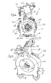
- zeigt das Hydraulikaggregat der Erfindung in einer perspektivischen Ansicht mit Blick schräg auf das abtriebsseitige Ende des Elektromotors.
- Fig. 2
- zeigt das Hydraulikaggregat aus
Fig. 1 in einer Seitenansicht. - Fig. 3
- zeigt das Hydraulikaggregat in einer Vorderansicht auf die Abtriebsseite des Elektromotors.
- Fig. 4
- zeigt das A-Lagerschild ohne weitere Komponenten in einer perspektivischen Ansicht.
- Fig. 5
- zeigt in einer perspektivischen Ansicht ein Flurförderzeug nach der Erfindung, welches ein Hydraulikaggregat gemäß den
Fig. 1 - 3 enthält. - Fig. 6
- zeigt in einer Teilschnittansicht den Vorderrahmen des Flurförderzeugs aus
Fig. 5 mit darin eingebauten Betriebsaggregaten, u. a. auch mit dem Hydraulikaggregat nach der Erfindung. - Das Hydraulikaggregat 1 gemäß
Fig. 1 umfasst einen Elektromotor 2, bei dem es sich um einen modifizierten Serien-Elektromotor handelt, wobei die Modifikation darin besteht, dass der ursprüngliche abtriebsseitige Motorgehäusedeckel durch einen abgewandelten Motorgehäusedeckel 4 ersetzt worden ist. Bei dem Gehäusedeckel 4 handelt es sich um ein A-Lagerschild, welches inFig. 4 in Alleinstellung dargestellt ist. Es weist eine Deckelkappe 6 auf, an welcher unten Befestigungsmittel 8 zur Befestigung des Hydraulikaggregats 1 an einem Rahmen (vgl. 70 inFig. 6 ) vorgesehen sind. Auf der gegenüberliegenden oberen Seite weist das A-Lagerschild 4 an seiner Deckelkappe 6 einen Halteadapter 10 zur Befestigung eines Steuerventilblocks 12 auf. Der Halteadapter 10 steht in Bezug auf die zentrale Längsachse X radial nach außen von dem A-Lagerschild 4 bzw. von dessen Deckelkappe 6 ab und weist an seinem abstehenden Ende eine Konsole 14 auf. Die Konsole 14 hat Anschlagflächen 16 und Aussparungen 18, wobei es sich um Montagehilfsanschlagelemente handelt, die mit entsprechenden komplementären Elementen des Steuerventilblocks 12 in Eingriff zu bringen sind (vgl. 18 inFig. 1 ). Die Konsole weist ferner Gewindebohrungen 20 zur Fixierung des Steuerventilblocks 12 auf, der seinerseits Bohrungen 19 zur Durchführung von Befestigungsschrauben aufweist. In Umfangsrichtung der Deckelkappe 6 versetzt zu dem Halteadapter 10 ist eine Momentenstütze 22 an dem A-Lagerschild 4 vorgesehen, die ein weiteres Befestigungsmittel darstellt. Stirnseitig weist das A-Lagerschild eine zentrale Öffnung 24 für den Motorwellendurchtritt auf. An dieser Öffnung ist ferner ein Wellenlager 26 vorgesehen. Die Gewindebohrungen 28 sind Befestigungsstellen zur Fixierung einer Pumpe 30 in der in denFig. 1 - 3 gezeigten Position am stirnseitigen Ende des A-Lagerschildes 4. - Das A-Lagerschild 4 weist gemäß
Fig. 4 ferner Befestigungsstellen 32 zu seiner Fixierung an dem übrigen Motorgehäuse 3 des Elektromotors 2 auf. - Wie insbesondere aus den
Fig. 1 und 2 zu ersehen ist, hat der Elektromotor ein grob umrissen zylindrisches Motorengehäuse 3, welches in Längsrichtung durch ein hinteres B-Lagerschild 34 einerseits und durch das schon erläuterte A-Lagerschild 4 andererseits abgeschlossen ist. Im mittleren Teil der Längsseite des Gehäuses 3 sind Kühlrippen 36 vorgesehen. - Auf der Konsole 14 des Halteadapters 10 ist in den
Fig. 1 bis 3 der Steuerventilblock 12 fixiert und so positioniert, dass er sich im Wesentlichen parallel zur Längsachse X erstreckt, ohne dabei über das hintere Ende 38 des Motors 2 hinaus und über das vordere Ende 40 der Pumpe 30 hinaus in Längsrichtung nennenswert abzustehen. - Der Ventilblock 12 ist mittels einer elektrischen Steuereinrichtung ansteuerbar, um den Hydraulikfluss zu und von hydraulischen Verbrauchern zu steuern, die an dem Ventilblock 12 anzuschließen sind. An dem pumpenseitigen Ende 42 des Ventilblocks 12 ist ein Hydraulikfluidfilter 44 vorgesehen, welches über eine Hydraulikleitung 46 (Druckleitung) mit der Druckseite der Pumpe 30 verbunden ist, so dass von der Pumpe gefördertes Hydraulikfluid vor dem Eintritt in den Steuerventilblock 12 der Filter 44 durchströmt und dort gefiltert wird.
- Die Komponenten Steuerventilanordnung 12, 44, Pumpe 30 und Druckleitung 46 sind einzeln austauschbar montiert, was Wartung und Service erheblich vereinfacht. Auch kann der Filter 44 bei Bedarf leicht von dem Steuerventilblock 12 separiert werden.
- Wie die
Fig. 1 - 3 erkennen lassen, stellt das erfindungsgemäße Hydraulikaggregat 1 eine kompakte Baueinheit dar, wobei der Halteadapter 10 die Steuerventilanordnung aus Steuerventilblock 12 und Filter 44 radial so weit vom Elektromotor 2 entfernt hält, dass ein Kühlluftstrom dazwischen hindurchtreten kann. - Das relativ kostengünstig realisierbare, einfach zu wartende und kompakte Hydraulikaggregat 1 nach der Erfindung kann z. B. in einem Flurförderzeug gemäß
Fig. 5 in der inFig. 6 näher erkennbaren Weise eingebaut sein, um verschiedene hydraulische Verbraucher zu versorgen. - Bei dem Flurförderzeug gemäß
Fig. 5 handelt es sich um einen Elektrogabelstapler mit einer hydraulischen Hubeinrichtung 60. Die Hubeinrichtung 60 umfasst ein Hubgerüst 62, an dem Lasttraggabeln 64 mittels hydraulischer Hubzylinder anhebbar und absenkbar sind, um Lasten aufzunehmen und zu transportieren. Zur hydraulischen Versorgung und Steuerung der hydraulischen Hubzylinder ist ein Hydraulikaggregat 1, wie es in denFig. 1 - 3 gezeigt ist, vorgesehen. Das Hydraulikaggregat 1 ist inFig. 6 in seiner Einbaulage zwischen einer Antriebsvorderachse 66 des Flurförderzeugs und einem Hydrauliktank 68 im Vorderrahmenbereich 70 des Flurförderzeugs 59 dargestellt. Aufgrund seiner kompakten Bauweise erlaubt das erfindungsgemäße Hydraulikaggregat 1 eine Platz sparende Unterbringung der weiteren Komponenten 66, 68 im Vorderrahmenbereich 70. In der Teilschnittdarstellung gemäßFig. 6 ist die Verbindungsleitung zwischen der Pumpe und dem Filter des Hydraulikaggregats 1 nicht eingezeichnet. Der Filter ist inFig. 6 geschnitten zu erkennen.
Claims (12)
- Hydraulikaggregat mit einer Hydraulikpumpe (30), die an einen Hydraulikfluidtank anschließbar ist, einem Elektromotor (2) als Antriebsmittel für die Hydraulikpumpe (30), der eine Motorwelle und einen Motorgehäusedeckel (4) aufweist, und einer an der Pumpe (30) angeschlossenen Steuerventilanordnung (12) zur Steuerung wenigstens eines an die Pumpe (30) anschließbaren und von der Pumpe (30) mit Hydraulikfluid aus dem Hydraulikfluidtank zu versorgenden hydraulischen Verbrauchers,
dadurch gekennzeichnet, dass die Pumpe (30) an dem Motorgehäusedeckel (4) befestigt ist und dass der Motorgehäusedeckel (4) einen Halteadapter (10) aufweist, an dem die Steuerventilanordnung (12) befestigt ist. - Hydraulikaggregat nach Anspruch 1, dadurch gekennzeichnet, dass der Motorgehäusedeckel (4) ein A-Lagerschild des Elektromotors (2) ist.
- Hydraulikaggregat nach Anspruch 1 oder 2, dadurch gekennzeichnet, dass der Halteadapter (10) in Bezug auf die Motorwelle quer, insbesondere radial nach außen von dem Motorgehäusedeckel (4) absteht und an seinem abstehenden Ende eine Konsole (14) aufweist, auf welcher die Steuerventilanordnung (12) aufgenommen ist.
- Hydraulikaggregat nach einem der vorhergehenden Ansprüche, dadurch gekennzeichnet, dass die Steuerventilanordnung (12) eine zu einem Steuerventilblock zusammengefasste Baueinheit ist.
- Hydraulikaggregat nach Anspruch 4, dadurch gekennzeichnet, dass der Ventilblock (12) und der Halteadapter (10) einander komplementäre Montagehilfsanschlagflächen (16, 18) aufweisen, die miteinander in Eingriff stehen.
- Hydraulikaggregat nach einem der vorhergehenden Ansprüche, dadurch gekennzeichnet, dass die Steuerventilanordnung (12) einen Hydraulikfluidfilter (44) aufweist.
- Hydraulikaggregat nach einem der vorhergehenden Ansprüche, dadurch gekennzeichnet, dass der Motorgehäusedeckel (4) Befestigungsmittel (8) zur Befestigung des Hydraulikaggregats an einem Rahmen, insbesondere Fahrzeugrahmen aufweist.
- Hydraulikaggregat nach einem der vorher gehenden Ansprüche, dadurch gekennzeichnet, dass die Pumpe (30) mit der Steuerventilanordnung (12) vermittels einer Hydraulikfluidleitung (46) hydraulisch verbunden ist.
- Hydraulikaggregat nach einem der vorhergehenden Ansprüche, dadurch gekennzeichnet, dass die Steuerventilanordnung (12) und die Pumpe (30) lösbar und somit austauschbar an dem Motordeckel (4) befestigt sind und dass die Pumpe (30) und die Steuerventilanordnung (12) voneinander separierbar sind.
- A-Lagerschild für einen Elektromotor, umfassend eine im Wesentlichen zylindrische Deckelkappe (6) mit einem radial davon abstehenden Halteadapter (10) der zur Aufnahme und Fixierung eines hydraulischen Steuerventilblocks (12) eingerichtet ist, und Befestigungsmittel zur Anbringung einer Pumpe (30).
- Flurförderzeug mit einer Hubeinrichtung, die ein Hubgerüst mit einem daran auf und ab bewegbaren Lastaufnahmemittel aufweist und hydraulisch steuerbar ist, um das Lastaufnahmemittel am Hubgerüst zu heben bzw. zu senken, gekennzeichnet durch ein Hydraulikaggregat nach einem der Ansprüche 1 bis 9 zur hydraulischen Versorgung und Steuerung der Hubeinrichtung.
- Flurförderzeug nach Anspruch 11, dadurch gekennzeichnet, dass es eine hydraulische Lenkeinrichtung aufweist und dass das Hydraulikaggregat dazu eingerichtet ist, auch die Lenkeinrichtung hydraulisch zu versorgen und zu steuern.
Applications Claiming Priority (1)
| Application Number | Priority Date | Filing Date | Title |
|---|---|---|---|
| DE102010062936A DE102010062936A1 (de) | 2010-12-13 | 2010-12-13 | Hydraulikaggregat |
Publications (2)
| Publication Number | Publication Date |
|---|---|
| EP2463228A1 true EP2463228A1 (de) | 2012-06-13 |
| EP2463228B1 EP2463228B1 (de) | 2013-08-07 |
Family
ID=45218504
Family Applications (1)
| Application Number | Title | Priority Date | Filing Date |
|---|---|---|---|
| EP11193258.8A Active EP2463228B1 (de) | 2010-12-13 | 2011-12-13 | Hydraulikaggregat |
Country Status (3)
| Country | Link |
|---|---|
| US (1) | US9493329B2 (de) |
| EP (1) | EP2463228B1 (de) |
| DE (1) | DE102010062936A1 (de) |
Cited By (1)
| Publication number | Priority date | Publication date | Assignee | Title |
|---|---|---|---|---|
| CN110002370A (zh) * | 2019-05-13 | 2019-07-12 | 安徽维德电源有限公司 | 一种电动叉车驱动及液压集成动力系统及其控制方法 |
Families Citing this family (10)
| Publication number | Priority date | Publication date | Assignee | Title |
|---|---|---|---|---|
| CN103508382B (zh) * | 2012-06-26 | 2015-10-21 | 安庆联动属具股份有限公司 | 多档调压装置 |
| CN106369008B (zh) * | 2016-10-19 | 2017-12-15 | 西南石油大学 | 一种螺杆驱动的管内液压站 |
| CN107975509A (zh) * | 2017-12-27 | 2018-05-01 | 徐工集团工程机械有限公司 | 行走马达集成阀盖及行走马达 |
| JP1663520S (de) * | 2019-07-29 | 2020-07-13 | ||
| JP1663497S (de) * | 2019-07-29 | 2020-07-13 | ||
| USD924938S1 (en) | 2019-07-29 | 2021-07-13 | Hawe Hydraulik Se | Housing portion for a hydraulic pump |
| USD969441S1 (en) * | 2020-09-11 | 2022-11-08 | Doosan Industrial Vehicle Co., Ltd. | Forklift |
| USD969442S1 (en) * | 2020-09-28 | 2022-11-08 | Doosan Industrial Vehicle Co., Ltd. | Forklift |
| USD1001412S1 (en) * | 2022-10-11 | 2023-10-10 | Manitou Bf | Forklift truck |
| US20240240658A1 (en) * | 2023-01-17 | 2024-07-18 | Narendra Gupta | Hydraulic power pack module |
Citations (3)
| Publication number | Priority date | Publication date | Assignee | Title |
|---|---|---|---|---|
| DE19959022C1 (de) * | 1999-12-08 | 2001-06-21 | Bosch Gmbh Robert | Antriebseinheit |
| DE102004032256B3 (de) * | 2004-07-03 | 2005-12-15 | Jungheinrich Ag | Hydraulikaggregat für Flurförderzeuge |
| DE102006021682A1 (de) * | 2006-05-10 | 2007-11-15 | Jungheinrich Ag | Hydraulikaggregat |
Family Cites Families (22)
| Publication number | Priority date | Publication date | Assignee | Title |
|---|---|---|---|---|
| US3086618A (en) * | 1959-10-14 | 1963-04-23 | Lars Arnbak & Company | Method and means for increasing the load capacity of lift trucks |
| US3079750A (en) * | 1959-10-27 | 1963-03-05 | Audley Engineering Co Ltd | Thrust applying mechanism |
| US3179020A (en) * | 1962-12-07 | 1965-04-20 | Houdaille Industries Inc | Hydraulic rotary actuator vane seal |
| US3400953A (en) * | 1966-06-27 | 1968-09-10 | Int Harvester Co | Hydraulic tubing connector with vibration damping means |
| US4123201A (en) * | 1973-09-04 | 1978-10-31 | Central Scientific Company, Inc. | Modular vacuum pump assembly |
| DE3227926C4 (de) * | 1982-07-27 | 1995-07-13 | Knapp Mikrohydraulik Gmbh | Hydraulikeinheit |
| DE3729216A1 (de) | 1987-09-02 | 1989-03-16 | Teves Gmbh Alfred | Hydraulikaggregat |
| US4824334A (en) * | 1987-11-02 | 1989-04-25 | Ramsay Ronald D | Modular hydraulic power system |
| DE4219462A1 (de) * | 1992-06-13 | 1993-12-16 | Rexroth Mannesmann Gmbh | Hydraulik-Aggregat |
| AT401380B (de) * | 1992-08-12 | 1996-08-26 | Weber Gisela | Hydraulikaggregat für ausgleichsrampen |
| DE4416173C2 (de) * | 1994-05-06 | 1996-05-30 | Jungheinrich Ag | Hydraulische Hubvorrichtung für batteriebetriebene Flurförderzeuge oder dergleichen |
| DE19725093A1 (de) * | 1997-06-13 | 1998-12-17 | Itt Mfg Enterprises Inc | Hydraulisches Aggregat |
| DE19725092A1 (de) * | 1997-06-13 | 1998-12-17 | Itt Mfg Enterprises Inc | Hydraulisches Aggregat |
| DE19739233A1 (de) * | 1997-09-09 | 1999-03-11 | Mannesmann Rexroth Ag | Hydraulikaggregat |
| DE19936644B4 (de) * | 1999-08-04 | 2004-04-01 | Hella Kg Hueck & Co. | Elektrische Luftpumpe für Kraftfahrzeuge |
| US6431845B1 (en) * | 2000-06-09 | 2002-08-13 | Gast Manufacturing, Inc. | Head cover assembly with monolithic valve plate |
| DE10307622B4 (de) * | 2003-02-22 | 2010-08-05 | Linde Material Handling Gmbh | Antriebsachse mit integriertem Elektromotor für eine Hydraulikpumpe |
| DE202005005620U1 (de) * | 2005-04-08 | 2006-08-17 | Hawe Hydraulik Gmbh & Co. Kg | Pumpenaggregat |
| DE102005055193B4 (de) | 2005-11-19 | 2008-03-13 | J. S. Staedtler Gmbh & Co. Kg | Mine für Schreib-, Zeichen- oder Malgeräte |
| KR101163848B1 (ko) * | 2009-12-02 | 2012-07-09 | 기아자동차주식회사 | 전동식 진공펌프 |
| US8147219B2 (en) * | 2010-02-16 | 2012-04-03 | Heng Sheng Precision Tech. Co., Ltd. | Motor direct driven compressor system |
| EP2642122B1 (de) * | 2012-03-21 | 2014-05-21 | HAWE Hydraulik SE | Pumpenaggregat |
-
2010
- 2010-12-13 DE DE102010062936A patent/DE102010062936A1/de not_active Withdrawn
-
2011
- 2011-12-12 US US13/316,739 patent/US9493329B2/en active Active
- 2011-12-13 EP EP11193258.8A patent/EP2463228B1/de active Active
Patent Citations (3)
| Publication number | Priority date | Publication date | Assignee | Title |
|---|---|---|---|---|
| DE19959022C1 (de) * | 1999-12-08 | 2001-06-21 | Bosch Gmbh Robert | Antriebseinheit |
| DE102004032256B3 (de) * | 2004-07-03 | 2005-12-15 | Jungheinrich Ag | Hydraulikaggregat für Flurförderzeuge |
| DE102006021682A1 (de) * | 2006-05-10 | 2007-11-15 | Jungheinrich Ag | Hydraulikaggregat |
Cited By (2)
| Publication number | Priority date | Publication date | Assignee | Title |
|---|---|---|---|---|
| CN110002370A (zh) * | 2019-05-13 | 2019-07-12 | 安徽维德电源有限公司 | 一种电动叉车驱动及液压集成动力系统及其控制方法 |
| CN110002370B (zh) * | 2019-05-13 | 2024-01-05 | 安徽维德电源有限公司 | 一种电动叉车驱动及液压集成动力系统及其控制方法 |
Also Published As
| Publication number | Publication date |
|---|---|
| US9493329B2 (en) | 2016-11-15 |
| DE102010062936A1 (de) | 2012-06-14 |
| EP2463228B1 (de) | 2013-08-07 |
| US20120145486A1 (en) | 2012-06-14 |
Similar Documents
| Publication | Publication Date | Title |
|---|---|---|
| EP2463228B1 (de) | Hydraulikaggregat | |
| WO2009146908A1 (de) | Kompressorsystem zur druckluftversorgung eines nutzfahrzeugs und verfahren zum betreiben eines kompressorsystems | |
| DE102009023079A1 (de) | Rundschalttisch | |
| EP3981633A1 (de) | Antriebs- und lenkeinheit für flurförderfahrzeuge | |
| DE102011011863A1 (de) | Fahrmischer für fließfähige Medien, insbesondere Beton | |
| DE102010036238A1 (de) | Feder-Dämpfer-Einheit zur Höhenverstellung eines Fahrzeuges | |
| DE2159289A1 (de) | Antriebsvorrichtung für Winden | |
| WO2004098965A1 (de) | Höhenverstellbare stütze für sattelauflieger oder dgl | |
| DE202012101199U1 (de) | Markise | |
| DE10307622A1 (de) | Antriebsachse mit integriertem Elektromotor für eine Hydraulikpumpe | |
| DE102013020118A1 (de) | Mobilkran | |
| DE102012214193A1 (de) | Lenkbare Antriebsvorrichtung für ein Flurförderfahrzeug | |
| EP1466858B1 (de) | Hochregalflurförderzeug mit einer Antriebseinheit | |
| EP2562058B1 (de) | Modular aufgebaute Stützvorrichtung für einen Sattelanhänger und Sattelanhänger mit einer solchen Stützvorrichtung | |
| DE2832352A1 (de) | Kraftstoff-foerderpumpe | |
| EP2986850A1 (de) | Kompressorsystem mit kupplung | |
| DE10325127A1 (de) | Antriebseinrichtung mit einem Fahrantrieb und einer Arbeitshydraulik | |
| EP1770000B1 (de) | Kraftfahrzeug mit Lenkhilfepumpe und Luftpresser | |
| DE102019209060A1 (de) | Antriebseinheit für ein Flurförderzeug, Antriebsachse für ein Flurförderzeug, Flurförderzeug und Verfahren zur Montage einer Antriebseinheit für ein Flurförderfahrzeug | |
| DE20009278U1 (de) | Vorrichtung zum Anheben von Fahrzeugen mittels Wagenheber | |
| EP2184199B1 (de) | Selbstfahrende lenkbare Arbeitsmaschine | |
| DE102011079492A1 (de) | Antriebsvorrichtung für ein Flurförderzeug | |
| DE102009027285A1 (de) | Antriebseinheit einer Scheibenwischvorrichtung in einem Fahrzeug | |
| DE10146592C1 (de) | Hinterachsträger eines Kraftfahrzeuges | |
| EP3873791B1 (de) | Fahrzeug mit einer tragstruktur |
Legal Events
| Date | Code | Title | Description |
|---|---|---|---|
| PUAI | Public reference made under article 153(3) epc to a published international application that has entered the european phase |
Free format text: ORIGINAL CODE: 0009012 |
|
| AK | Designated contracting states |
Kind code of ref document: A1 Designated state(s): AL AT BE BG CH CY CZ DE DK EE ES FI FR GB GR HR HU IE IS IT LI LT LU LV MC MK MT NL NO PL PT RO RS SE SI SK SM TR |
|
| AX | Request for extension of the european patent |
Extension state: BA ME |
|
| 17P | Request for examination filed |
Effective date: 20121016 |
|
| RIC1 | Information provided on ipc code assigned before grant |
Ipc: F15B 13/08 20060101ALI20121219BHEP Ipc: B66F 9/22 20060101AFI20121219BHEP |
|
| GRAP | Despatch of communication of intention to grant a patent |
Free format text: ORIGINAL CODE: EPIDOSNIGR1 |
|
| GRAS | Grant fee paid |
Free format text: ORIGINAL CODE: EPIDOSNIGR3 |
|
| GRAA | (expected) grant |
Free format text: ORIGINAL CODE: 0009210 |
|
| AK | Designated contracting states |
Kind code of ref document: B1 Designated state(s): AL AT BE BG CH CY CZ DE DK EE ES FI FR GB GR HR HU IE IS IT LI LT LU LV MC MK MT NL NO PL PT RO RS SE SI SK SM TR |
|
| REG | Reference to a national code |
Ref country code: GB Ref legal event code: FG4D Free format text: NOT ENGLISH |
|
| REG | Reference to a national code |
Ref country code: CH Ref legal event code: EP Ref country code: AT Ref legal event code: REF Ref document number: 625676 Country of ref document: AT Kind code of ref document: T Effective date: 20130815 |
|
| REG | Reference to a national code |
Ref country code: IE Ref legal event code: FG4D Free format text: LANGUAGE OF EP DOCUMENT: GERMAN |
|
| REG | Reference to a national code |
Ref country code: DE Ref legal event code: R096 Ref document number: 502011001162 Country of ref document: DE Effective date: 20131002 |
|
| REG | Reference to a national code |
Ref country code: NL Ref legal event code: VDEP Effective date: 20130807 |
|
| REG | Reference to a national code |
Ref country code: LT Ref legal event code: MG4D |
|
| PG25 | Lapsed in a contracting state [announced via postgrant information from national office to epo] |
Ref country code: HR Free format text: LAPSE BECAUSE OF FAILURE TO SUBMIT A TRANSLATION OF THE DESCRIPTION OR TO PAY THE FEE WITHIN THE PRESCRIBED TIME-LIMIT Effective date: 20130807 Ref country code: SE Free format text: LAPSE BECAUSE OF FAILURE TO SUBMIT A TRANSLATION OF THE DESCRIPTION OR TO PAY THE FEE WITHIN THE PRESCRIBED TIME-LIMIT Effective date: 20130807 Ref country code: NO Free format text: LAPSE BECAUSE OF FAILURE TO SUBMIT A TRANSLATION OF THE DESCRIPTION OR TO PAY THE FEE WITHIN THE PRESCRIBED TIME-LIMIT Effective date: 20131107 Ref country code: CY Free format text: LAPSE BECAUSE OF FAILURE TO SUBMIT A TRANSLATION OF THE DESCRIPTION OR TO PAY THE FEE WITHIN THE PRESCRIBED TIME-LIMIT Effective date: 20130828 Ref country code: IS Free format text: LAPSE BECAUSE OF FAILURE TO SUBMIT A TRANSLATION OF THE DESCRIPTION OR TO PAY THE FEE WITHIN THE PRESCRIBED TIME-LIMIT Effective date: 20131207 Ref country code: PT Free format text: LAPSE BECAUSE OF FAILURE TO SUBMIT A TRANSLATION OF THE DESCRIPTION OR TO PAY THE FEE WITHIN THE PRESCRIBED TIME-LIMIT Effective date: 20131209 Ref country code: LT Free format text: LAPSE BECAUSE OF FAILURE TO SUBMIT A TRANSLATION OF THE DESCRIPTION OR TO PAY THE FEE WITHIN THE PRESCRIBED TIME-LIMIT Effective date: 20130807 |
|
| PG25 | Lapsed in a contracting state [announced via postgrant information from national office to epo] |
Ref country code: SI Free format text: LAPSE BECAUSE OF FAILURE TO SUBMIT A TRANSLATION OF THE DESCRIPTION OR TO PAY THE FEE WITHIN THE PRESCRIBED TIME-LIMIT Effective date: 20130807 Ref country code: GR Free format text: LAPSE BECAUSE OF FAILURE TO SUBMIT A TRANSLATION OF THE DESCRIPTION OR TO PAY THE FEE WITHIN THE PRESCRIBED TIME-LIMIT Effective date: 20131108 Ref country code: FI Free format text: LAPSE BECAUSE OF FAILURE TO SUBMIT A TRANSLATION OF THE DESCRIPTION OR TO PAY THE FEE WITHIN THE PRESCRIBED TIME-LIMIT Effective date: 20130807 Ref country code: LV Free format text: LAPSE BECAUSE OF FAILURE TO SUBMIT A TRANSLATION OF THE DESCRIPTION OR TO PAY THE FEE WITHIN THE PRESCRIBED TIME-LIMIT Effective date: 20130807 Ref country code: NL Free format text: LAPSE BECAUSE OF FAILURE TO SUBMIT A TRANSLATION OF THE DESCRIPTION OR TO PAY THE FEE WITHIN THE PRESCRIBED TIME-LIMIT Effective date: 20130807 Ref country code: PL Free format text: LAPSE BECAUSE OF FAILURE TO SUBMIT A TRANSLATION OF THE DESCRIPTION OR TO PAY THE FEE WITHIN THE PRESCRIBED TIME-LIMIT Effective date: 20130807 |
|
| PG25 | Lapsed in a contracting state [announced via postgrant information from national office to epo] |
Ref country code: CY Free format text: LAPSE BECAUSE OF FAILURE TO SUBMIT A TRANSLATION OF THE DESCRIPTION OR TO PAY THE FEE WITHIN THE PRESCRIBED TIME-LIMIT Effective date: 20130807 |
|
| PG25 | Lapsed in a contracting state [announced via postgrant information from national office to epo] |
Ref country code: EE Free format text: LAPSE BECAUSE OF FAILURE TO SUBMIT A TRANSLATION OF THE DESCRIPTION OR TO PAY THE FEE WITHIN THE PRESCRIBED TIME-LIMIT Effective date: 20130807 Ref country code: CZ Free format text: LAPSE BECAUSE OF FAILURE TO SUBMIT A TRANSLATION OF THE DESCRIPTION OR TO PAY THE FEE WITHIN THE PRESCRIBED TIME-LIMIT Effective date: 20130807 Ref country code: RO Free format text: LAPSE BECAUSE OF FAILURE TO SUBMIT A TRANSLATION OF THE DESCRIPTION OR TO PAY THE FEE WITHIN THE PRESCRIBED TIME-LIMIT Effective date: 20130807 Ref country code: SK Free format text: LAPSE BECAUSE OF FAILURE TO SUBMIT A TRANSLATION OF THE DESCRIPTION OR TO PAY THE FEE WITHIN THE PRESCRIBED TIME-LIMIT Effective date: 20130807 Ref country code: DK Free format text: LAPSE BECAUSE OF FAILURE TO SUBMIT A TRANSLATION OF THE DESCRIPTION OR TO PAY THE FEE WITHIN THE PRESCRIBED TIME-LIMIT Effective date: 20130807 |
|
| PG25 | Lapsed in a contracting state [announced via postgrant information from national office to epo] |
Ref country code: IT Free format text: LAPSE BECAUSE OF FAILURE TO SUBMIT A TRANSLATION OF THE DESCRIPTION OR TO PAY THE FEE WITHIN THE PRESCRIBED TIME-LIMIT Effective date: 20130807 Ref country code: ES Free format text: LAPSE BECAUSE OF FAILURE TO SUBMIT A TRANSLATION OF THE DESCRIPTION OR TO PAY THE FEE WITHIN THE PRESCRIBED TIME-LIMIT Effective date: 20130807 |
|
| PLBE | No opposition filed within time limit |
Free format text: ORIGINAL CODE: 0009261 |
|
| STAA | Information on the status of an ep patent application or granted ep patent |
Free format text: STATUS: NO OPPOSITION FILED WITHIN TIME LIMIT |
|
| BERE | Be: lapsed |
Owner name: JUNGHEINRICH A.G. Effective date: 20131231 |
|
| 26N | No opposition filed |
Effective date: 20140508 |
|
| REG | Reference to a national code |
Ref country code: DE Ref legal event code: R097 Ref document number: 502011001162 Country of ref document: DE Effective date: 20140508 |
|
| PG25 | Lapsed in a contracting state [announced via postgrant information from national office to epo] |
Ref country code: LU Free format text: LAPSE BECAUSE OF FAILURE TO SUBMIT A TRANSLATION OF THE DESCRIPTION OR TO PAY THE FEE WITHIN THE PRESCRIBED TIME-LIMIT Effective date: 20131213 |
|
| REG | Reference to a national code |
Ref country code: IE Ref legal event code: MM4A |
|
| PG25 | Lapsed in a contracting state [announced via postgrant information from national office to epo] |
Ref country code: BE Free format text: LAPSE BECAUSE OF NON-PAYMENT OF DUE FEES Effective date: 20131231 Ref country code: IE Free format text: LAPSE BECAUSE OF NON-PAYMENT OF DUE FEES Effective date: 20131213 |
|
| PG25 | Lapsed in a contracting state [announced via postgrant information from national office to epo] |
Ref country code: MC Free format text: LAPSE BECAUSE OF FAILURE TO SUBMIT A TRANSLATION OF THE DESCRIPTION OR TO PAY THE FEE WITHIN THE PRESCRIBED TIME-LIMIT Effective date: 20130807 |
|
| PG25 | Lapsed in a contracting state [announced via postgrant information from national office to epo] |
Ref country code: SM Free format text: LAPSE BECAUSE OF FAILURE TO SUBMIT A TRANSLATION OF THE DESCRIPTION OR TO PAY THE FEE WITHIN THE PRESCRIBED TIME-LIMIT Effective date: 20130807 |
|
| PG25 | Lapsed in a contracting state [announced via postgrant information from national office to epo] |
Ref country code: TR Free format text: LAPSE BECAUSE OF FAILURE TO SUBMIT A TRANSLATION OF THE DESCRIPTION OR TO PAY THE FEE WITHIN THE PRESCRIBED TIME-LIMIT Effective date: 20130807 |
|
| PG25 | Lapsed in a contracting state [announced via postgrant information from national office to epo] |
Ref country code: RS Free format text: LAPSE BECAUSE OF FAILURE TO SUBMIT A TRANSLATION OF THE DESCRIPTION OR TO PAY THE FEE WITHIN THE PRESCRIBED TIME-LIMIT Effective date: 20131107 Ref country code: BG Free format text: LAPSE BECAUSE OF FAILURE TO SUBMIT A TRANSLATION OF THE DESCRIPTION OR TO PAY THE FEE WITHIN THE PRESCRIBED TIME-LIMIT Effective date: 20130807 Ref country code: MK Free format text: LAPSE BECAUSE OF FAILURE TO SUBMIT A TRANSLATION OF THE DESCRIPTION OR TO PAY THE FEE WITHIN THE PRESCRIBED TIME-LIMIT Effective date: 20130807 Ref country code: HU Free format text: LAPSE BECAUSE OF FAILURE TO SUBMIT A TRANSLATION OF THE DESCRIPTION OR TO PAY THE FEE WITHIN THE PRESCRIBED TIME-LIMIT; INVALID AB INITIO Effective date: 20111213 |
|
| REG | Reference to a national code |
Ref country code: CH Ref legal event code: PL |
|
| PG25 | Lapsed in a contracting state [announced via postgrant information from national office to epo] |
Ref country code: MT Free format text: LAPSE BECAUSE OF FAILURE TO SUBMIT A TRANSLATION OF THE DESCRIPTION OR TO PAY THE FEE WITHIN THE PRESCRIBED TIME-LIMIT Effective date: 20130807 |
|
| PG25 | Lapsed in a contracting state [announced via postgrant information from national office to epo] |
Ref country code: LI Free format text: LAPSE BECAUSE OF NON-PAYMENT OF DUE FEES Effective date: 20141231 Ref country code: CH Free format text: LAPSE BECAUSE OF NON-PAYMENT OF DUE FEES Effective date: 20141231 |
|
| REG | Reference to a national code |
Ref country code: FR Ref legal event code: PLFP Year of fee payment: 5 |
|
| REG | Reference to a national code |
Ref country code: FR Ref legal event code: PLFP Year of fee payment: 6 |
|
| REG | Reference to a national code |
Ref country code: FR Ref legal event code: PLFP Year of fee payment: 7 |
|
| REG | Reference to a national code |
Ref country code: AT Ref legal event code: MM01 Ref document number: 625676 Country of ref document: AT Kind code of ref document: T Effective date: 20161213 |
|
| PG25 | Lapsed in a contracting state [announced via postgrant information from national office to epo] |
Ref country code: AT Free format text: LAPSE BECAUSE OF NON-PAYMENT OF DUE FEES Effective date: 20161213 |
|
| PG25 | Lapsed in a contracting state [announced via postgrant information from national office to epo] |
Ref country code: AL Free format text: LAPSE BECAUSE OF FAILURE TO SUBMIT A TRANSLATION OF THE DESCRIPTION OR TO PAY THE FEE WITHIN THE PRESCRIBED TIME-LIMIT Effective date: 20130807 |
|
| P01 | Opt-out of the competence of the unified patent court (upc) registered |
Effective date: 20230628 |
|
| PGFP | Annual fee paid to national office [announced via postgrant information from national office to epo] |
Ref country code: GB Payment date: 20231220 Year of fee payment: 13 |
|
| GBPC | Gb: european patent ceased through non-payment of renewal fee |
Effective date: 20241213 |
|
| PG25 | Lapsed in a contracting state [announced via postgrant information from national office to epo] |
Ref country code: GB Free format text: LAPSE BECAUSE OF NON-PAYMENT OF DUE FEES Effective date: 20241213 |
|
| PGFP | Annual fee paid to national office [announced via postgrant information from national office to epo] |
Ref country code: FR Payment date: 20251218 Year of fee payment: 15 |
|
| PGFP | Annual fee paid to national office [announced via postgrant information from national office to epo] |
Ref country code: DE Payment date: 20251222 Year of fee payment: 15 |