EP2462794B1 - Machine agricole - Google Patents
Machine agricole Download PDFInfo
- Publication number
- EP2462794B1 EP2462794B1 EP11192836.2A EP11192836A EP2462794B1 EP 2462794 B1 EP2462794 B1 EP 2462794B1 EP 11192836 A EP11192836 A EP 11192836A EP 2462794 B1 EP2462794 B1 EP 2462794B1
- Authority
- EP
- European Patent Office
- Prior art keywords
- machine
- tractor
- agricultural machine
- working depth
- sensor
- Prior art date
- Legal status (The legal status is an assumption and is not a legal conclusion. Google has not performed a legal analysis and makes no representation as to the accuracy of the status listed.)
- Not-in-force
Links
Images


Classifications
-
- A—HUMAN NECESSITIES
- A01—AGRICULTURE; FORESTRY; ANIMAL HUSBANDRY; HUNTING; TRAPPING; FISHING
- A01B—SOIL WORKING IN AGRICULTURE OR FORESTRY; PARTS, DETAILS, OR ACCESSORIES OF AGRICULTURAL MACHINES OR IMPLEMENTS, IN GENERAL
- A01B63/00—Lifting or adjusting devices or arrangements for agricultural machines or implements
- A01B63/02—Lifting or adjusting devices or arrangements for agricultural machines or implements for implements mounted on tractors
- A01B63/10—Lifting or adjusting devices or arrangements for agricultural machines or implements for implements mounted on tractors operated by hydraulic or pneumatic means
- A01B63/111—Lifting or adjusting devices or arrangements for agricultural machines or implements for implements mounted on tractors operated by hydraulic or pneumatic means regulating working depth of implements
- A01B63/1112—Lifting or adjusting devices or arrangements for agricultural machines or implements for implements mounted on tractors operated by hydraulic or pneumatic means regulating working depth of implements using a non-tactile ground distance measurement, e.g. using reflection of waves
-
- A—HUMAN NECESSITIES
- A01—AGRICULTURE; FORESTRY; ANIMAL HUSBANDRY; HUNTING; TRAPPING; FISHING
- A01B—SOIL WORKING IN AGRICULTURE OR FORESTRY; PARTS, DETAILS, OR ACCESSORIES OF AGRICULTURAL MACHINES OR IMPLEMENTS, IN GENERAL
- A01B63/00—Lifting or adjusting devices or arrangements for agricultural machines or implements
- A01B63/02—Lifting or adjusting devices or arrangements for agricultural machines or implements for implements mounted on tractors
- A01B63/10—Lifting or adjusting devices or arrangements for agricultural machines or implements for implements mounted on tractors operated by hydraulic or pneumatic means
- A01B63/1006—Lifting or adjusting devices or arrangements for agricultural machines or implements for implements mounted on tractors operated by hydraulic or pneumatic means the hydraulic or pneumatic means structurally belonging to the tractor
-
- A—HUMAN NECESSITIES
- A01—AGRICULTURE; FORESTRY; ANIMAL HUSBANDRY; HUNTING; TRAPPING; FISHING
- A01C—PLANTING; SOWING; FERTILISING
- A01C9/00—Potato planters
Definitions
- the present invention relates to an agricultural machine with at least one tool.
- the agricultural machine can be provided as a lifting machine without suspension and is connected via a hydraulic power lift with at least one lifting cylinder raised and lowered connected to a tractor.
- the machine can also be designed as a drawn machine with its own chassis, wherein the machine has at least one lifting cylinder for lifting at least one tool.
- the towed machine can be connected to a drawbar of a tractor.
- Trailed machines have, for example, a lifting cylinder for lifting the tool, by means of which the working depth can be adjusted by the driver by means of a manual control to a desired value. It is not possible to maintain a constant working depth.
- Lifting machines are connected to the three-point hitch of a tractor and regulated by the handlebars of the tractor in their position with respect to the soil to be processed.
- Modern tractors have this electronic hitch control (EHR), in which either the tensile force or the change in position of the mounted lifting machine is detected on the handlebars of the tractor.
- EHR electronic hitch control
- the handlebars there may be force measuring devices on the handlebars and a position sensor in the region of the three-point coupling to measure the tensile force or position during operation.
- the electronic hoist control By means of the electronic hoist control, the known regulations draft control, position control, mixing controls and floating position are possible. The type of regulation is selected depending on the tool which is arranged on the agricultural machine. For example is used in plowing or loosening tools, such as a zinc rotor, the draft control.
- a disadvantage of the mentioned control method is that fluctuations in the soil condition and unevenness of the soil or vorseilende movements and vibrations of the tractor can not be sufficiently compensated.
- the DE 32 35 818 A1 shows a mounted flight, which can be coupled as a lifting machine to a tractor, but also has its own jockey wheel.
- the altitude of the jockey wheel can be determined and adjusted by the EHR of the tractor via its own cylinder, so that the position of the cultivation flight can be additionally controlled.
- speed sensors are arranged in the region of the support wheel and a rear wheel of the tractor.
- both the working depth of the cultivation flight can be regulated, as well as a slip-dependent control are made when a certain slip value is exceeded.
- the EHR of the tractor must be adjusted to the control by the manufacturer, and subsequent modifications to the EHR are generally not possible.
- the beats DE 35 01 568 A1 to detect the absolute movement of the lifting machine directly on the machine or on the tillage tool by means of a motion sensor, for example an accelerometer.
- a motion sensor for example an accelerometer.
- the absolute movement of the lifting machine forms the control variable for the EHR of the tractor.
- the GB 2 184 331 A shows a plow that is connectable as a lifting machine to a three-point hitch of a tractor.
- the working depth of the plow is detected by a distance sensor attached to the plow.
- the signal of the sensor is merely processed and displayed and made a manual correction of the working depth by the operator who operates the lifting cylinder for this purpose.
- an automatic regulation of the working depth can be provided. Again, however, the signal of the sensor acts on the tractor's own control unit, which operates according to the lifting cylinder of the tractor.
- the DE 199 45 853 A1 shows a running as a lifting plow, which also has an additional support wheel.
- the support wheel can be controlled by means of a hydraulic cylinder via the EHR of the tractor to change the altitude of the plow by adjusting the height of the support wheel.
- the tracking of the Stauerradposition takes place here as a slave function of the control of the hoist position as a master function.
- the main function of the hoist control is possible in the usual way in position control, traction control or mixed control.
- Object of the present invention is to propose an agricultural machine, which allows independent of the electronic hitch control of the tractor improvement of the depth control of the tools.
- An agricultural machine is designed as a lifting machine without chassis and has at least one tool.
- the agricultural machine can be raised and lowered by a hydraulic power lift with at least one lifting cylinder connected to a tractor, which has an electronic hoist control (EHR), which includes an electronic control unit and a control block with control valves.
- EHR electronic hoist control
- a device for regulating the working depth of the at least one tool is arranged, wherein by means of the device for regulating the working depth during operation at least one lifting cylinder of the hydraulic power lift of the tractor can be controlled.
- the device according to the invention for regulating the working depth is arranged directly on the attachment, it can operate independently of the electro-hydraulic control device of the tractor and instead act on the at least one lifting cylinder of the hydraulic power lift of the tractor.
- the agricultural machine can therefore be operated regardless of the manufacturer with a variety of tractors without the tractor or the EHR of the tractor must be matched to the agricultural machine.
- an improvement in the depth control of the tools can be achieved.
- the machine-specific device for regulating the working depth controls either directly by means of machine-own electrical or hydraulic units at least one lifting cylinder of the hydraulic power lift of the tractor.
- the device comprises at least one sensor arranged on the machine for detecting the working depth of the tool.
- the device for regulating the working depth comprises, in addition to the at least one sensor, a machine-specific electrical or electronic control unit. Operational the machine, the at least one sensor is connected to an input of the machine-specific control unit and the machine-specific control unit connected by at least one electrical connection line with a control block of the tractor. The control unit of the tractor is in turn driven by the machine's own control unit. In this version, no intervention is required in the tractor-owned EHR control unit.
- the device in addition to the at least one sensor arranged on the machine, also comprises an operating unit which can be arranged on the tractor. Furthermore, the device comprises at least one electrical connection line, by means of which the sensor is connected to the operating unit during operation of the machine.
- the operating unit is in turn connected to a control block of the tractor to switch the control signals of the operating unit to the control block.
- the control block of the tractor thus receives its signals from the control unit instead of a tractor's own EHR control unit. It is particularly advantageous in this embodiment that no interventions in the tractor's EHR control unit are required.
- the device arranged on the machine here comprises an electrical or electronic control device, a control block with at least one control valve and at least one sensor arranged on the machine for detecting the working depth of the attachment.
- the sensor is in this case connected to an input of the attachment's own control device and the control valve acts on the at least one lifting cylinder of the tractor.
- the control can be adapted in an optimal manner to the tool according to the requirements or the execution of the tool to be controlled.
- the device for regulating the working depth is therefore structurally particularly simple, since it requires no additional actuators, unlike other solutions, but already uses existing lifting cylinder.
- the control can also act purely mechanically on the control unit.
- To connect the machine control block with the pump and the lifting cylinder of the tractor hydraulic lines are provided. All lines are connected to the tractor via quick disconnectable hydraulic couplings.
- Such an embodiment is also applicable to a drawn machine in an analogous manner, in which case the at least one control valve acts on a lifting cylinder of the drawn agricultural machine.
- control of the at least one lifting cylinder is carried out via load sensing, for which a further control line is required. It is particularly advantageous that the hydraulic pump only promotes when the consumer is active.
- the device has hydraulic connection lines and hydraulic couplings, by means of which it can be connected to a pump of the EHR of the tractor and to the at least one lifting cylinder of the power lift of the tractor. Furthermore, the device has a return line, by means of which it is connectable to a reservoir of the tractor.
- the inventive device for regulating the working depth it is possible to control the hoist of the tractor instead of the EHR of the tractor by the corresponding machine side arranged device for regulating the working depth.
- a particularly accurate and direct detection of the working depth or of the parameters to be controlled can take place here in contrast to a tapping of the measuring signals on the hoist. It is particularly advantageous in this case that this can not adversely affect the working depth of the tools by disturbances due to vibrations or anticipatory tractor movements.
- the device can still be structurally simple and inexpensive to run, since they can use the tractor anyway existing facilities, such as pump and return.
- the inventive device for regulating the working depth of combined machines in which several operations are performed simultaneously and thus the exact depth control of the various tools with respect to subsequent or leading tools is particularly important.
- the invention can be applied in a particularly advantageous manner, since the exact depth control not only in relation to any jamming movements of the tractor, but also on subsequent tools is of great importance.
- the agricultural machine is a combined machine with at least one loosening tool, a planting device with a reservoir and at least one set of sets and a downstream device for Enddammied.
- the working depth of the loosening tool can be regulated by means of the device for regulating the working depth. In this way it can be achieved in potato plants that the soil is loosened evenly to a certain depth, the seed deposit takes place uniformly at a constant depth and caused by the uniformly deep soil loosening even dams with a constant coverage of the plants.
- the senor for this purpose is arranged directly in the tool, preferably the loosening tool and detects a vertical distance of the loosening tool to the ground.
- the sensor is in this case designed as an ultrasonic sensor.
- the sensor detects a vertical distance of the loosening tool to the setting crowd.
- a predetermined value which is preferably adjustable
- the agricultural machine can be raised or lowered in such a way, that the working depth of the loosening tool again reaches the desired value, while the Dammformblech and the set share maintain their position due to their floating storage. It is ensured that the distance between the upper edge of the dam to the shelf remains the same. Likewise, the distance from the footpad to the processing horizon remains the same. Since the potato tubers preferably grow in the loosened area and avoid the unprocessed soil, a constant working depth under the support sole is fundamentally important.
- the rod harrow When harvesting, the rod harrow is guided over the dam roller running on the dam. If this distance is not equal due to different cutting depths, crop and quality losses occur due to cut tubers. Likewise, at different cutting depths, it may happen that the rod harrow is guided too deep and picks up unprocessed soil. As a result, clods get into the crop, which damage it and can be removed with great effort. Especially under wet conditions, the dam roll can no longer support the joist on the softened dam. The wet soil is pressed to the tubers and can hardly be separated. Likewise, the crowd gets caught in the subsoil and a uniform Rodearbeit is no longer possible. These problems can be avoided by the inventive device for regulating the working depth. These control functions are therefore necessary because of varying soil types, soil moisture, seed tank levels of the soil and the tire press differently.
- the senor detects a level of loosened earth material in the device for Enddammopathic. Since the level of loosened earth material is dependent on the working depth of the leading loosening tool, this can also be done by a constant and accurate depth control of the loosening tool.
- the senor is arranged on a suspension of the setting crowd. Due to the floating bearing of the set of shares, the sensor can detect the relative vertical distance of the loosening tool to the setting crowd in a favorable manner.
- the setting share is mounted on the machine in a floating manner via a spacer, for example a cam, which preferably acts on the suspension of the setting share.
- An advantageous embodiment of the invention provides for this purpose that the setting crowd is mounted on a height-adjustable manner acting on the suspension of the set share cam on the agricultural machine and the working depth of the loosening tool in relation to the set of shares by turning the cam is adjustable. In this way, a desired distance between setting crowd and loosening tool can be preset.
- the cam can be controlled or rotated, so that in case of deviations from the preset working depth tracking of the loosening tool is possible.
- Another advantageous embodiment of the invention provides that in the direction of travel in front of the loosening tool, a roller extending in the transverse direction of the agricultural machine is arranged in a height-adjustable manner.
- the working depth of the loosening tool is thus preset by adjusting the height of the roller. It is also particularly advantageous here, when the roller is adjustable during operation, in order to keep the working depth of the loosening tool constant even during operation.
- a sensor can do this For example, also detect a vertical distance between the roller and the loosening tool.
- the roller or the wheels by a hydraulic accumulator with a preferably adjustable weight can be loaded.
- the reconsolidation of the soil can be improved, while a lower load on the roller, the weight is transferred to the tractor and there provides better traction and less slippage.
- this device can be supplied in conjunction with the machine's own control unit by the already existing tractor hydraulics.
- a sensor for the depth regulation of the machine is present on the adjustable roller or the height-adjustable wheels.
- An advantageous development of the invention provides that two or more sensors are arranged on the machine to detect the working depth of the loosening tool via various parameters (for example, distance setting share / loosening tool, level of the Dammformblechs, height above the ground, etc.). By means of the control unit, the sensor is then selected, via which the regulation of the working depth should be made. Likewise, mixed control over several or all sensors are possible.
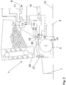
- the Fig. 1-3 5 and 6 show an agricultural machine 1 in an embodiment as a lifting machine without own chassis 31 in an overview.
- the agricultural machine 1 is designed as a combined potato planter and has a loosening tool 2, a planting device 3 with a reservoir 4, a removal device 5 for the seedlings and a Setzschar 6.
- the Setzschar 6 downstream of a device for Enddammied 7, which presently in Form of a Dammformblechs is formed.
- the exact depth guidance of the tools is of particular importance in this case, since only a uniformly loosened earth material allows Graphgutablage in a constant depth and a uniform dam structure with a uniform coverage of Graphgut.
- the machine can be coupled to a tractor 10 via a hydraulic power lift 8, which has at least one lifting cylinder 9.
- a hydraulic power lift 8 which has at least one lifting cylinder 9.
- the lower links 11 of the tractor 10 can be raised or lowered.
- the position of the agricultural machine 1 via the upper link 12, optionally by means of a further lifting cylinder 9, are influenced.
- the tractor 10 has a conventional electronic hitch control 13 (EHR), which includes a hydraulic oil tank 14, a pump 15, an electronic control unit 16 and a control block 17 with control valves. Furthermore, the EHR 13 of the tractor 10 comprises at least one sensor 18 for measuring the tensile force and / or the position of the links 11, 12 of the hoist 8. This allows the agricultural machine 1 operated in a known manner with traction control, position control, mixing control or floating position become.
- EHR electronic hitch control 13
- the machine 1 now has a machine-side device 19 for regulating the working depth, which in operation acts on the at least one lifting cylinder 9 of the hydraulic power lift 8 either directly instead of the tractor's own EHR 13 or indirectly using the control block 17 of the EHR.
- the device 19 comprises at least one sensor 20, which in the present case detects the working depth of the loosening tool 2.
- the senor 20 is disposed directly on the loosening tool 2 and measures the processing depth of the loosening tool 2 against the bottom 21.
- the device 19 comprises an electronic control unit 22 and a control block 23 with at least one control valve which controls the lifting cylinder or the 9 of the tractor 10 , By means of hydraulic connecting lines 24 and hydraulic couplings 32, the control block 23 with the pump 15 and with the at least a lifting cylinder 9 connected. Via a return line 25 of the control block 23 is connected to the hydraulic oil tank 14 of the tractor 10.
- the agricultural machine here is still structurally simple, since this uses existing hydraulic components of the tractor 10 and only the controller consisting of the control unit 16 and control block 17, replaced by machine-specific devices 22 and 23.
- the agricultural machine 1 can thereby be used in conjunction with any tugs 10, since it is only necessary to connect the connecting lines 24 and the return line 25 to the corresponding hydraulic lines of the tractor 10. Interventions in the control unit 16 of the tractor 10 are thereby not required.
- a sensor 20 for example, an ultrasonic sensor is suitable, which measures the distance A of the loosening tool 2 to the bottom 21.
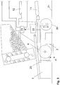
- FIG. 2 A detail of an agricultural machine 1 in execution as a lifting machine shows Fig. 2 ,
- the setting crowd 6 and the device 7 for Enddammied here are floating on the agricultural machine 1 stored so that they can follow bumps and Thus, a constant working depth with respect to the ground surface 21 can always be achieved.
- the setting crowd 6 and the dam molding plate 7 are mounted on a common suspension 26 on the agricultural machine 1, so that they always maintain the same relative vertical distance from each other. In this way it can be achieved that in relation to the resulting dam the planting material is always stored in the same planting depth.
- the vertical distance between the Dammformblech 7 and the Setzschar 6 via a perforated rail 27 can be preset, so that the desired planting depth is adjustable.
- the loosening tool 2 is in contrast fixedly mounted on the agricultural machine 1 and thus adjustable via the hydraulic power lift 8 of the tractor 10 in its working depth.
- the setting share 6 rests on the suspension 26 on a cam 28.
- the cam 28 By turning the cam 28 is thus a vertical distance A 'between the setting set 6 and the loosening tool 2 adjustable.
- the cam disk 28 is arranged on a rotatable shaft 29, which extends over the width of the machine 1 and has an adjusting device (not shown). This makes it possible to preset the vertical distance A 'between the setting set 6 and the loosening tool 2 and thus the working depth of the loosening tool 2 to a desired level. If the loosening tool 2 is set a few centimeters lower than the set of sets 6, a uniform loose soil layer is present below the planting material, which promotes the growth of Graphgut.
- a sensor 20 is in this case arranged in the region of the suspension 26 of the set 6 and detects the distance to the cam 28, which in turn is a measure of the distance A 'between set 6 and loosening tool 2 or a measure of the working depth of the loosening tool 2.
- the shaft 29 is for this purpose by a link or another cylinder, which is controlled by the control unit 22 and the control block 23 (indicated by a dash-dot line of action), hinged and can be rotated in the appropriate direction.
- the hydraulic supply also takes place here by the tractor. If, during operation of the machine 1, for example as a result of unevenness in the ground, the coulters 6 are lifted off, this is detected by the sensor 20 and readjusted by turning the cam plate 28.
- the agricultural machine 1 By means of the agricultural machine 1 according to the invention it is thus possible in an advantageous manner, not only to ensure exact depth guidance of the tools 2 to a constant working depth, regardless of soil conditions and uneven floors, but also the processing depth relative to the planting depth or a working depth set other tools and keep them constant during operation. Furthermore, it is possible by the adjustment of the vertical distance A 'between the setting set 6 and the loosening tool 2, a wear of the loosening tool 2, for example, the tines of a tine rotor, compensate by the loosening tool 2 is set lower.
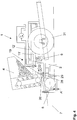
- Fig. 3 shows another embodiment in which the working depth of the loosening tool 2 by a height-adjustable (in the present case indicated by a double arrow) arranged on the agricultural machine 1 roller 30 is adjustable.
- the roller 30 extends in the transverse direction of the agricultural machine in the direction of travel in front of the loosening tool 2 and serves in addition to the adjustment of the working depth of the loosening tool 2 a uniform crumbling of the bottom 21.
- the height position of the roller 30 via an adjusting device, not shown can be preset.
- a tracking of the height position of the roller 30 during operation to adjust the working depth of the loosening tool 2 can also be provided here by the adjustment of the roller by the controller 22 and the control block 23 is controlled (dash-dotted line of action).
- a sensor 35 for detecting the working depth of the loosening tool 2 is presently arranged in the dam molding plate or the device for Enddammied 7 and detects the level of loosened earth material within the Dammformblechs, which also represents a measure of the working depth of the loosening tool 2.
- Registered the sensor 20, for example, a too low level in the dam molding plate 7, 9 is lowered by appropriate action of the lifting cylinder 9, the machine and thus the loosening tool 2 and thus engages deeper into the bottom 21 a.
- the loosening tool 2 or the machine 1 can be dug out accordingly by the lifting cylinder 9.
- a plurality of sensors 35 may be arranged in the dam molding plate 7 in order to detect different levels correctly.
- a uniform coverage of the stored Rooguts or a uniform distance of the lower edge of the setting crowd 6 and the upper edge of the Dammformers 7 can be ensured thereby in a particularly favorable manner. If a control of the roller is provided, the readjustment of the working depth can be carried out additionally or instead by raising or lowering the roller 30.
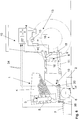
- Fig. 4 shows another advantageous embodiment, in which the agricultural machine 1 as a towed machine with its own chassis 31 is executed.
- the agricultural machine 1 is in this case connected to a trailer hitch of a tractor (not shown here) and has at least one lifting cylinder 9 for lifting one or more tools.
- the loosening tool 2, the setting set 6 and the device for Enddammied 7 a first link 12 ', while the reservoir 4 is arranged on a second link 11'.
- Analogous to the in Fig. 2 illustrated design of a lifting machine are again the dam molding plate 7 and the setting set 6 fixed, but mutually adjustable in their relative height connected to each other and stored floating on the machine 1.
- the loosening tool 2 is fixedly arranged on the machine 1 and can be lowered or raised correspondingly via the lifting cylinder 9.
- the adjustment of the distance A 'between the loosening tool 2 and the setting share 6 takes place as in Fig. 2 described via a arranged on a rotatable shaft 29 cam 28th
- the machine 1 comprises a device 19 for regulating the working depth of the loosening tool 2, as shown in FIG Fig. 2 described.
- the shaft 29 can be rotated accordingly during operation in order to regulate the distance A 'between the loosening tool 2 and the setting share 6 to a desired constant level.
- the operative connection between the shaft 29 and the control unit 22 and the control block 23 is again shown by a dashed line.
- the working depth of the loosening tool 2 also strongly depends on the filling of the reservoir 4, which is supported with its weight on the loosening tool, by means of the device 19 according to the invention despite strongly fluctuating levels a constant working depth of the tools be achieved.
- hydraulic connection lines 24 were always provided between the tractor and the attached or attached machine in order to realize an improved regulation of the working depth by using already existing hydraulic components of the tractor.
- the device 19 includes a sensor 20 for detecting the distance A 'between setting set 6 and loosening tool 2 and a sensor 35 for detecting the fill level in the shaped dam plate 7.
- the device 19 comprises a machine-specific control unit 22 which processes the sensor signals (cf. thick, dash-dotted lines) and which is connected by an electrical connection line 34 with the control block 17 of the tractor 10. The machine-specific control unit 22 thus acts on the control block 17 instead of the control unit 16 of the tractor 10.
- control unit 22 can be preset here, whether the control of the distance A 'between Setzschar 6 and loosening tool 2 or after the level in the Dammformblech 7 should take place , which both represent a measure of the working depth of the loosening tool. Likewise, a mixed control is possible.
- the devices 19 for regulating the working depth comprises only the sensors 20, 35, in some circumstances even only a single sensor 20.
- Suitable sensors 20, for example ultrasonic sensors are here, possibly by integrated circuits in the sensor 20 for signal processing, in able to output signal, which is directly suitable for controlling the control block.
- the device 19 in this case comprises at least one sensor 20, but here also two sensors 20 and 35, which measure the working depth of the loosening tool 2 or a corresponding size.
- the control unit 33 in turn acts on the control block 17 of the tractor 10 instead of the control unit 16.
- the control unit 33 is designed in the manner of a joystick and includes four different switching positions, as shown by the four arrows indicated. After a first switching position, the machine can be manually lowered by the operator and raised manually after another switching position. Two other switching positions are designed as locking positions and allow automatic control of the working depth as described in the previous embodiments.
- control is carried out according to the distance A 'between setting set 6 and loosening tool 2.
- the sensor 20 is energized in this latching position by an electrical connection line 34 and outputs a distance A' corresponding signal to the control unit 33, which in turn Control block 17 acted upon accordingly.
- the senor 20 is designed as a displacement sensor and includes three areas. From 0% to 25% of the way the machine is lowered and from 75% to 100% of the way the machine is raised. By contrast, no signal is output from 25% -75% of the way, ie in a middle range, which corresponds to an optimum depth of the tools. hereby can be a constant readjustment, which can lead to unwanted vibrations, can be effectively prevented.
- the operating unit 33 includes according to the described embodiment, a control unit 22 'for processing the sensor signals and then passes the control signal to the control block 17 of the tractor on. Unlike the in FIG. 5 In this case, it is also possible to integrate further control functions by the operating unit 33. However, it is also possible in this embodiment with an operating unit 33 to use sensors 20, 35 whose signal is directly suitable for driving the control block 17. In this case, the sensor signals are only forwarded by the operating unit 33 to the control block 17, so that only electrical connecting lines 34 from the operating unit 33 to the sensors 20, 35 are required and the wiring can be realized in a particularly simple manner.
- the machine 1 as in FIG. 5 shown a machine-own control unit 22 which acts on the control block 17 of the tractor 10 when the corresponding locking position is selected on the control unit 33.
- the control unit 22 is then also connected via the connecting lines 34 with the operating unit 33, which passes the control signals only to the control block 17 of the tractor 10.
- one or more lifting cylinders 9 of the tractor 10 is driven by the attachment machine 1 either directly or via the control block 17 of the tractor 10 while eliminating the tractor's own control unit 16.
- software intervention in the control unit 16 are not required, so that the attachment machine 1 can be used with any tractor.
- the tractor 10 can be used in a conventional manner for other work, since no changes to the controller 16 are made. The conversion is possible by means of a simple multiple plug, which is attached to the control block 17 of the EHR.
Landscapes
- Life Sciences & Earth Sciences (AREA)
- Soil Sciences (AREA)
- Environmental Sciences (AREA)
- Engineering & Computer Science (AREA)
- Mechanical Engineering (AREA)
- Lifting Devices For Agricultural Implements (AREA)
Claims (12)
- Machine agricole (1) comportant au moins un outil (2), la machine agricole (1) pouvant être reliée en tant que machine de levage à un relevage hydraulique (8) d'un tracteur (10), et l'outil (2) et/ou la machine agricole (1) pouvant être relevé(s) et abaissé(s) par au moins un vérin de levage (9) du relevage hydraulique (8) du tracteur (10), le tracteur possédant une commande de mécanisme de levage électronique (EHR) avec un appareil de commande électronique (16) et un bloc de commande hydraulique (17) avec des vannes de commande, un dispositif (19) propre à la machine pour régler la profondeur de travail de l'au moins un outil (2) étant disposé sur la machine (1), lequel dispositif comporte au moins un capteur (20) disposé sur la machine (1) pour détecter la profondeur de travail de l'outil (2), caractérisée en ce que le dispositif (19) pour la régulation de la profondeur de travail comprend également un appareil de commande (22) électrique ou électronique propre à la machine, et en ce que le dispositif (19) commande l'au moins un vérin de levage (9) du relevage hydraulique (8) pendant le fonctionnement de la machine (1), dans laquelle, pendant le fonctionnement de la machine (1), le au moins un capteur (20) est relié à une entrée de l'appareil de commande (22) propre à la machine et l'appareil de commande (22) propre à la machine est reliée au bloc de commande hydraulique (17) du tracteur (10) par au moins une ligne de connexion électrique (34), et dans laquelle l'appareil de commande (22) propre à la machine agit sur le bloc de commande (17) du tracteur au lieu de l'appareil de commande (16) du tracteur.
- Machine agricole selon la revendication 1, caractérisée en ce que le dispositif (19) comprend une unité de commande (33) qui peut être disposée sur le tracteur (10), sachant que, pendant le fonctionnement de la machine (1), l'appareil de commande (22) est relié à l'unité de commande (33) par une ligne de connexion électrique (34) et sachant que l'unité de commande (33) est reliée à un bloc de commande (17) du tracteur (10).
- Machine agricole selon l'une des revendications précédentes, caractérisée en ce que la machine agricole (1) est une machine combinée et comporte au moins un outil d'ameublissement (2), un dispositif de plantation (3) avec un réservoir de stockage (4) et au moins un soc planteur (6) ainsi qu'un dispositif en aval pour la constitution de la butte d'extrémité (7), le soc planteur (6) et le dispositif pour la constitution de la butte d'extrémité (7) étant montés sur palier flottant sur la machine agricole (1) et l'outil d'ameublissement (2) étant monté de manière fixe sur la machine agricole (1), et en ce que la profondeur de travail de l'outil d'ameublissement (2) peut être réglée au moyen du dispositif de réglage de la profondeur de travail (19).
- Machine agricole selon la revendication précédente, caractérisée en ce que le capteur (20), de préférence un capteur à ultrasons, capte une distance verticale de l'outil d'ameublissement (2) à partir du sol (21).
- Machine agricole selon la revendication 3, caractérisée en ce que le capteur (20) capte une distance verticale de l'outil d'ameublissement (2) à partir du soc planteur (6), sachant que le capteur (20) est de préférence disposé sur une suspension (26) du soc planteur (6).
- Machine agricole selon l'une des revendications précédentes, caractérisée en ce qu' un capteur (35) capte un niveau de remplissage en terre ameublie dans le dispositif pour la constitution de la butte d'extrémité (7).
- Machine agricole selon l'une des revendications 3-6, caractérisée en ce que le soc planteur (6) est maintenu à une distance minimale de l'outil d'ameublissement (2) dans chaque état de fonctionnement via un écarteur, en particulier un disque à cames (28), agissant de préférence sur la suspension (26) du soc planteur (6).
- Machine agricole selon l'une des revendications 3-7 , caractérisée en ce que le soc planteur (6) est monté sur la machine agricole (1) de manière réglable en hauteur via un disque à cames (28) agissant sur la suspension (26) du soc planteur (6) et que la profondeur de travail de l'outil d'ameublissement (2) par rapport au soc planteur (6) est réglable par rotation du disque à cames (28), de préférence, également pendant le fonctionnement.
- Machine agricole selon l'une des revendications précédentes, caractérisée en ce qu' un rouleau (30) s'étendant dans le sens transversal de la machine agricole (1) et/ou plusieurs roues disposées côte à côte sont disposées sur la machine agricole (1) devant l'outil d'ameublissement (2) dans le sens de déplacement, de manière réglable en hauteur, et la profondeur de travail de l'outil d'ameublissement (2) est réglable en hauteur par réglage en hauteur du rouleau ou des roues (30), de préférence, également pendant le fonctionnement.
- Machine agricole selon l'une des revendications précédentes, caractérisée en ce qu' un capteur pour le réglage de la profondeur de la machine existe sur le rouleau réglable (30) ou les roues réglables en hauteur.
- Machine agricole selon l'une des revendications 9 ou 10, caractérisée en ce que le rouleau (30) ou les roues peuvent être chargés par un accumulateur hydraulique avec un poids de préférence réglable.
- Machine agricole selon l'une des revendications précédentes, caractérisée en ce que deux capteurs (10, 35) au moins sont disposés sur la machine et la profondeur de travail peut être réglée par une commande proportionnelle entre deux ou plusieurs capteurs.
Applications Claiming Priority (1)
| Application Number | Priority Date | Filing Date | Title |
|---|---|---|---|
| DE102010062861A DE102010062861A1 (de) | 2010-12-10 | 2010-12-10 | Landwirtschaftliche Maschine |
Publications (2)
| Publication Number | Publication Date |
|---|---|
| EP2462794A1 EP2462794A1 (fr) | 2012-06-13 |
| EP2462794B1 true EP2462794B1 (fr) | 2018-11-28 |
Family
ID=45218453
Family Applications (1)
| Application Number | Title | Priority Date | Filing Date |
|---|---|---|---|
| EP11192836.2A Not-in-force EP2462794B1 (fr) | 2010-12-10 | 2011-12-09 | Machine agricole |
Country Status (2)
| Country | Link |
|---|---|
| EP (1) | EP2462794B1 (fr) |
| DE (1) | DE102010062861A1 (fr) |
Families Citing this family (12)
| Publication number | Priority date | Publication date | Assignee | Title |
|---|---|---|---|---|
| US9699954B2 (en) | 2015-06-30 | 2017-07-11 | Cnh Industrial America Llc | Adjustable down stop for agricultural closing discs |
| US9668401B2 (en) | 2015-06-30 | 2017-06-06 | Cnh Industrial America Llc | Down stop for agricultural closing discs |
| CN105165195A (zh) * | 2015-08-25 | 2015-12-23 | 西宁科进工业设计有限公司 | 一种播种机 |
| EP3243368B2 (fr) | 2016-05-10 | 2022-06-22 | CLAAS Tractor S.A.S. | Combinaison d'appareil de véhicule de traction ayant un système d'assistance au conducteur |
| DE102017105938A1 (de) | 2017-03-20 | 2018-09-20 | Andreas Heiß | Landwirtschaftliche Maschine |
| US11259454B2 (en) | 2017-04-28 | 2022-03-01 | Cnh Industrial America Llc | System and method for detecting ground engaging tool float for an agricultural implement |
| US10561056B2 (en) | 2017-04-28 | 2020-02-18 | Cnh Industrial America Llc | System and method for monitoring soil conditions within a field |
| US10779454B2 (en) | 2018-01-30 | 2020-09-22 | Exmark Manufacturing Company, Incorporated | Soil penetrating apparatus with depth control |
| DE102018106147A1 (de) * | 2018-03-16 | 2019-09-19 | Grimme Landmaschinenfabrik Gmbh & Co. Kg | Vorrichtung zur Herstellung von Querdämmen |
| CN108476680B (zh) * | 2018-03-20 | 2020-05-19 | 中国农业大学 | 微型马铃薯振动排序精量播种装置 |
| US20210315147A1 (en) * | 2020-04-08 | 2021-10-14 | Agco Corporation | Systems comprising agricultural implements connected to lifting hitches and related control systems and methods |
| CN112273038B (zh) * | 2020-10-21 | 2022-10-11 | 塔里木大学 | 一种促苗壮苗的棉花种植方法 |
Citations (7)
| Publication number | Priority date | Publication date | Assignee | Title |
|---|---|---|---|---|
| GB2184331A (en) | 1985-12-05 | 1987-06-24 | Kubota Ltd | Plowing depth detecting system for rotary plow |
| NL1014691C2 (nl) | 2000-03-20 | 2001-09-21 | Netagco Potato Division B V | Inrichting voor het poten van aardappelen. |
| WO2002049414A1 (fr) | 2000-12-21 | 2002-06-27 | Väderstad-Verken Ab | Dispositif de reglage pour machine agricole |
| EP1338934A1 (fr) | 2002-02-26 | 2003-08-27 | Claas Saulgau Gmbh | Méthode de réglage d'un tracteur agricole avec outil de travail de la terre |
| DE69724214T2 (de) | 1996-10-23 | 2004-03-25 | Cnh U.K. Ltd., Basildon | Verbessertes Kultivationsverfahren |
| DE102004048759A1 (de) | 2004-10-05 | 2006-04-13 | Landmaschinenfabrik Köckerling GmbH & Co KG | Verfahren und Vorrichtung zur Regelung der Ablagetiefe von Saatgut |
| WO2006087298A1 (fr) | 2005-02-17 | 2006-08-24 | Heiss Jun Andreas | Machine agricole combinee |
Family Cites Families (7)
| Publication number | Priority date | Publication date | Assignee | Title |
|---|---|---|---|---|
| DE3235818A1 (de) | 1982-09-28 | 1984-03-29 | Robert Bosch Gmbh, 7000 Stuttgart | Einrichtung zur steuerung der arbeitstiefe eines bodenbearbeitungsgeraetes |
| DE3501568A1 (de) | 1984-03-15 | 1985-09-19 | Mannesmann Rexroth GmbH, 8770 Lohr | Verfahren zur regelung eines anbaugeraets an landwirtschaftlichen schleppern |
| DE3611414A1 (de) | 1986-04-05 | 1987-10-08 | Helwig Dipl Ing Schmitt | Arbeitstiefenregelung an bodenbearbeitungsgeraeten |
| DE3734194A1 (de) * | 1987-10-09 | 1989-04-20 | Amazonen Werke Dreyer H | Landwirtschaftliche bestellkombination |
| DE4002172C1 (en) * | 1990-01-25 | 1991-08-14 | Fritz 8000 Muenchen De Marschall | Agricultural implement for preparing soil - has self propelled vehicle with platform which has movable working arm |
| DE19945853A1 (de) | 1999-09-24 | 2001-03-29 | Bosch Gmbh Robert | Einrichtung zur Steuerung der Arbeitstiefe eines Bodenbearbeitungsgeräts, insbesondere eines Pfluges |
| DE102005027586A1 (de) * | 2005-06-14 | 2007-01-04 | Claas Saulgau Gmbh | Verfahren und Vorrichtung zum Betreiben eines Vorsatzgerätes zum Ernten von stängeligem Erntegut |
-
2010
- 2010-12-10 DE DE102010062861A patent/DE102010062861A1/de not_active Withdrawn
-
2011
- 2011-12-09 EP EP11192836.2A patent/EP2462794B1/fr not_active Not-in-force
Patent Citations (8)
| Publication number | Priority date | Publication date | Assignee | Title |
|---|---|---|---|---|
| GB2184331A (en) | 1985-12-05 | 1987-06-24 | Kubota Ltd | Plowing depth detecting system for rotary plow |
| DE69724214T2 (de) | 1996-10-23 | 2004-03-25 | Cnh U.K. Ltd., Basildon | Verbessertes Kultivationsverfahren |
| NL1014691C2 (nl) | 2000-03-20 | 2001-09-21 | Netagco Potato Division B V | Inrichting voor het poten van aardappelen. |
| WO2002049414A1 (fr) | 2000-12-21 | 2002-06-27 | Väderstad-Verken Ab | Dispositif de reglage pour machine agricole |
| EP1338934A1 (fr) | 2002-02-26 | 2003-08-27 | Claas Saulgau Gmbh | Méthode de réglage d'un tracteur agricole avec outil de travail de la terre |
| EP1666996A2 (fr) | 2002-02-26 | 2006-06-07 | CLAAS Selbstfahrende Erntemaschinen GmbH | Procédé destiné à la commande de machines agricoles |
| DE102004048759A1 (de) | 2004-10-05 | 2006-04-13 | Landmaschinenfabrik Köckerling GmbH & Co KG | Verfahren und Vorrichtung zur Regelung der Ablagetiefe von Saatgut |
| WO2006087298A1 (fr) | 2005-02-17 | 2006-08-24 | Heiss Jun Andreas | Machine agricole combinee |
Non-Patent Citations (8)
| Title |
|---|
| ANONYMOUS: "Horsch Sä-Exaktor SE 2,5 - SE 3 - SE 4K", HORSCH MACHINE - BETRIEBSANLEITUNG, January 1995 (1995-01-01), pages 1 - 127, XP055628218 |
| ANONYMOUS: "Innovationsoffensive der Landtechnikhersteller", MAGAZINE AGRITECHNICA, 2005, XP055628210, Retrieved from the Internet <URL:https://www.eilbote-online.com/artikel/drei-gold-und-25-silbermedaillen-innovationsoffensive-der-landtechnikhersteller-5423/> |
| ANONYMOUS: "Traktorenlexicon: Fendt Favorit 816", WIKIBOOKS.ORG, 21 June 2019 (2019-06-21), XP055628220, Retrieved from the Internet <URL:https://de.wikibooks.org/wiki/Traktorenlexikon:_Fendt_Favorit_816> |
| DIPL.-ING. RÜDIGER FREIMANN: "Automation mobiler Arbeitsma- schinen - Gerät steuert Traktor", December 2003, VDI- VERLAG, Düsseldorf, article "Kapitel 1", pages: 1 - 56, XP055628781 |
| DIPL.-ING. RÜDIGER FREIMANN: "Automation mobiler Arbeitsma- schinen - Gerät steuert Traktor", vol. 57, part 134 December 2013, VDI- VERLAG, Düsseldorf, article "Kapitel 5-10", XP055628796 |
| FENDT: "BETRIEBSANLEITUNG - Fendt Favorit 816 - 824", April 1995, article "Kapitel 16-17", pages: 2-3, 34-45,120 - 123, XP055628802 |
| ISO: "Tractors and machinery for agriculture and forestry — Serial control and communications data network — Part 7: Implement messages application layer", ISO 11783-7, 1 May 2009 (2009-05-01), XP055277576 |
| KLEINE: "Köpfroder KR 6III Baujahr 1994", KLEINE - ERSATZTEILLISTE SPEZIAL, January 1994 (1994-01-01), XP055628214 |
Also Published As
| Publication number | Publication date |
|---|---|
| DE102010062861A1 (de) | 2012-06-14 |
| EP2462794A1 (fr) | 2012-06-13 |
Similar Documents
| Publication | Publication Date | Title |
|---|---|---|
| EP2462794B1 (fr) | Machine agricole | |
| EP3157318B1 (fr) | Unité de travail du sol et procédé de travail du sol pour le travail conservateur du sol | |
| EP3026997B1 (fr) | Matériel de travail du sol muni d'un système de rappuyage | |
| EP1757182B1 (fr) | Presse agricole | |
| EP3050416B1 (fr) | Appareil de travail du sol | |
| DE202006020531U1 (de) | Kombinierte landwirtschaftliche Maschine | |
| WO2018197505A1 (fr) | Engin de travail de sol dans le domaine de l'agriculture | |
| EP2556735A1 (fr) | Appareil de traitement de sol doté d'un dispositif de maintien d'une valeur limite de patinage à une profondeur de travail constante | |
| WO2016192973A1 (fr) | Dispositif de commande pour un tracteur, tracteur présentant un dispositif de commande et procédé pour un dispositif de commande | |
| EP3424287B1 (fr) | Dispositif et procédé de réglage du fonctionnement d'un outil porté hydraulique pour un véhicule | |
| EP3300557B1 (fr) | Dispositif et procédé de controle du fonctionnement d'un appareil isolé hydraulique d'un véhicule | |
| EP3300560A1 (fr) | Dispositif et procédé de réglage du fonctionnement d'un appareil de remorquage hydraulique d'un véhicule | |
| WO2020259970A1 (fr) | Herse étrille | |
| DE19945853A1 (de) | Einrichtung zur Steuerung der Arbeitstiefe eines Bodenbearbeitungsgeräts, insbesondere eines Pfluges | |
| EP2363013B1 (fr) | Combiné de semis doté d'un dispositif pour maintenir une valeur limite de glissement | |
| EP3698616B1 (fr) | Agencement de soc pourvu de rouleau de pression à régulation de la pression | |
| DE102005020563A1 (de) | Kombinierte landwirtschaftliche Maschine | |
| DE202010014789U1 (de) | Landwirtschaftliches Anbaugerät | |
| EP3701779B1 (fr) | Machine agricole et procédé de fonctionnement d'une machine agricole | |
| EP2835043A1 (fr) | Semoir combiné agricole tracté et procédé de transfert d'un semoir combiné agricole d'une position de transport en position de travail et inversement | |
| EP3895514B1 (fr) | Dispositif de traitement du sol agricole et combinaison de machines agricoles | |
| EP4292414A1 (fr) | Appareil de traitement du sol avec dispositif de guidage de profondeur | |
| DE102022109091A1 (de) | Landwirtschaftliche verteilmaschine mit einem verteilgestänge und verfahren zur lagesteuerung des verteilgestänges | |
| DE102022109092A1 (de) | Landwirtschaftliche verteilmaschine mit einem verteilgestänge und verfahren zur lagesteuerung des verteilgestänges | |
| DE69711585T2 (de) | Boden- und Feldbearbeitungsmaschine zur Bildung einer uniformen Feldbodenschicht |
Legal Events
| Date | Code | Title | Description |
|---|---|---|---|
| PUAI | Public reference made under article 153(3) epc to a published international application that has entered the european phase |
Free format text: ORIGINAL CODE: 0009012 |
|
| AK | Designated contracting states |
Kind code of ref document: A1 Designated state(s): AL AT BE BG CH CY CZ DE DK EE ES FI FR GB GR HR HU IE IS IT LI LT LU LV MC MK MT NL NO PL PT RO RS SE SI SK SM TR |
|
| AX | Request for extension of the european patent |
Extension state: BA ME |
|
| 17P | Request for examination filed |
Effective date: 20121205 |
|
| 17Q | First examination report despatched |
Effective date: 20151203 |
|
| GRAP | Despatch of communication of intention to grant a patent |
Free format text: ORIGINAL CODE: EPIDOSNIGR1 |
|
| STAA | Information on the status of an ep patent application or granted ep patent |
Free format text: STATUS: GRANT OF PATENT IS INTENDED |
|
| INTG | Intention to grant announced |
Effective date: 20180604 |
|
| GRAS | Grant fee paid |
Free format text: ORIGINAL CODE: EPIDOSNIGR3 |
|
| GRAA | (expected) grant |
Free format text: ORIGINAL CODE: 0009210 |
|
| STAA | Information on the status of an ep patent application or granted ep patent |
Free format text: STATUS: THE PATENT HAS BEEN GRANTED |
|
| AK | Designated contracting states |
Kind code of ref document: B1 Designated state(s): AL AT BE BG CH CY CZ DE DK EE ES FI FR GB GR HR HU IE IS IT LI LT LU LV MC MK MT NL NO PL PT RO RS SE SI SK SM TR |
|
| REG | Reference to a national code |
Ref country code: GB Ref legal event code: FG4D Free format text: NOT ENGLISH |
|
| REG | Reference to a national code |
Ref country code: CH Ref legal event code: EP |
|
| REG | Reference to a national code |
Ref country code: AT Ref legal event code: REF Ref document number: 1069119 Country of ref document: AT Kind code of ref document: T Effective date: 20181215 |
|
| REG | Reference to a national code |
Ref country code: DE Ref legal event code: R096 Ref document number: 502011015074 Country of ref document: DE |
|
| REG | Reference to a national code |
Ref country code: IE Ref legal event code: FG4D Free format text: LANGUAGE OF EP DOCUMENT: GERMAN |
|
| PGFP | Annual fee paid to national office [announced via postgrant information from national office to epo] |
Ref country code: NL Payment date: 20181229 Year of fee payment: 8 |
|
| REG | Reference to a national code |
Ref country code: LT Ref legal event code: MG4D |
|
| REG | Reference to a national code |
Ref country code: NL Ref legal event code: FP |
|
| PG25 | Lapsed in a contracting state [announced via postgrant information from national office to epo] |
Ref country code: IS Free format text: LAPSE BECAUSE OF FAILURE TO SUBMIT A TRANSLATION OF THE DESCRIPTION OR TO PAY THE FEE WITHIN THE PRESCRIBED TIME-LIMIT Effective date: 20190328 Ref country code: FI Free format text: LAPSE BECAUSE OF FAILURE TO SUBMIT A TRANSLATION OF THE DESCRIPTION OR TO PAY THE FEE WITHIN THE PRESCRIBED TIME-LIMIT Effective date: 20181128 Ref country code: BG Free format text: LAPSE BECAUSE OF FAILURE TO SUBMIT A TRANSLATION OF THE DESCRIPTION OR TO PAY THE FEE WITHIN THE PRESCRIBED TIME-LIMIT Effective date: 20190228 Ref country code: HR Free format text: LAPSE BECAUSE OF FAILURE TO SUBMIT A TRANSLATION OF THE DESCRIPTION OR TO PAY THE FEE WITHIN THE PRESCRIBED TIME-LIMIT Effective date: 20181128 Ref country code: LV Free format text: LAPSE BECAUSE OF FAILURE TO SUBMIT A TRANSLATION OF THE DESCRIPTION OR TO PAY THE FEE WITHIN THE PRESCRIBED TIME-LIMIT Effective date: 20181128 Ref country code: ES Free format text: LAPSE BECAUSE OF FAILURE TO SUBMIT A TRANSLATION OF THE DESCRIPTION OR TO PAY THE FEE WITHIN THE PRESCRIBED TIME-LIMIT Effective date: 20181128 Ref country code: LT Free format text: LAPSE BECAUSE OF FAILURE TO SUBMIT A TRANSLATION OF THE DESCRIPTION OR TO PAY THE FEE WITHIN THE PRESCRIBED TIME-LIMIT Effective date: 20181128 Ref country code: NO Free format text: LAPSE BECAUSE OF FAILURE TO SUBMIT A TRANSLATION OF THE DESCRIPTION OR TO PAY THE FEE WITHIN THE PRESCRIBED TIME-LIMIT Effective date: 20190228 |
|
| PGFP | Annual fee paid to national office [announced via postgrant information from national office to epo] |
Ref country code: DE Payment date: 20190103 Year of fee payment: 8 |
|
| PG25 | Lapsed in a contracting state [announced via postgrant information from national office to epo] |
Ref country code: PT Free format text: LAPSE BECAUSE OF FAILURE TO SUBMIT A TRANSLATION OF THE DESCRIPTION OR TO PAY THE FEE WITHIN THE PRESCRIBED TIME-LIMIT Effective date: 20190328 Ref country code: AL Free format text: LAPSE BECAUSE OF FAILURE TO SUBMIT A TRANSLATION OF THE DESCRIPTION OR TO PAY THE FEE WITHIN THE PRESCRIBED TIME-LIMIT Effective date: 20181128 Ref country code: GR Free format text: LAPSE BECAUSE OF FAILURE TO SUBMIT A TRANSLATION OF THE DESCRIPTION OR TO PAY THE FEE WITHIN THE PRESCRIBED TIME-LIMIT Effective date: 20190301 Ref country code: RS Free format text: LAPSE BECAUSE OF FAILURE TO SUBMIT A TRANSLATION OF THE DESCRIPTION OR TO PAY THE FEE WITHIN THE PRESCRIBED TIME-LIMIT Effective date: 20181128 Ref country code: SE Free format text: LAPSE BECAUSE OF FAILURE TO SUBMIT A TRANSLATION OF THE DESCRIPTION OR TO PAY THE FEE WITHIN THE PRESCRIBED TIME-LIMIT Effective date: 20181128 |
|
| PGFP | Annual fee paid to national office [announced via postgrant information from national office to epo] |
Ref country code: BE Payment date: 20181229 Year of fee payment: 8 |
|
| PG25 | Lapsed in a contracting state [announced via postgrant information from national office to epo] |
Ref country code: IT Free format text: LAPSE BECAUSE OF FAILURE TO SUBMIT A TRANSLATION OF THE DESCRIPTION OR TO PAY THE FEE WITHIN THE PRESCRIBED TIME-LIMIT Effective date: 20181128 Ref country code: CZ Free format text: LAPSE BECAUSE OF FAILURE TO SUBMIT A TRANSLATION OF THE DESCRIPTION OR TO PAY THE FEE WITHIN THE PRESCRIBED TIME-LIMIT Effective date: 20181128 Ref country code: DK Free format text: LAPSE BECAUSE OF FAILURE TO SUBMIT A TRANSLATION OF THE DESCRIPTION OR TO PAY THE FEE WITHIN THE PRESCRIBED TIME-LIMIT Effective date: 20181128 Ref country code: PL Free format text: LAPSE BECAUSE OF FAILURE TO SUBMIT A TRANSLATION OF THE DESCRIPTION OR TO PAY THE FEE WITHIN THE PRESCRIBED TIME-LIMIT Effective date: 20181128 |
|
| REG | Reference to a national code |
Ref country code: CH Ref legal event code: PL |
|
| REG | Reference to a national code |
Ref country code: DE Ref legal event code: R026 Ref document number: 502011015074 Country of ref document: DE |
|
| PLBI | Opposition filed |
Free format text: ORIGINAL CODE: 0009260 |
|
| PG25 | Lapsed in a contracting state [announced via postgrant information from national office to epo] |
Ref country code: MC Free format text: LAPSE BECAUSE OF FAILURE TO SUBMIT A TRANSLATION OF THE DESCRIPTION OR TO PAY THE FEE WITHIN THE PRESCRIBED TIME-LIMIT Effective date: 20181128 Ref country code: SK Free format text: LAPSE BECAUSE OF FAILURE TO SUBMIT A TRANSLATION OF THE DESCRIPTION OR TO PAY THE FEE WITHIN THE PRESCRIBED TIME-LIMIT Effective date: 20181128 Ref country code: RO Free format text: LAPSE BECAUSE OF FAILURE TO SUBMIT A TRANSLATION OF THE DESCRIPTION OR TO PAY THE FEE WITHIN THE PRESCRIBED TIME-LIMIT Effective date: 20181128 Ref country code: SM Free format text: LAPSE BECAUSE OF FAILURE TO SUBMIT A TRANSLATION OF THE DESCRIPTION OR TO PAY THE FEE WITHIN THE PRESCRIBED TIME-LIMIT Effective date: 20181128 Ref country code: EE Free format text: LAPSE BECAUSE OF FAILURE TO SUBMIT A TRANSLATION OF THE DESCRIPTION OR TO PAY THE FEE WITHIN THE PRESCRIBED TIME-LIMIT Effective date: 20181128 Ref country code: LU Free format text: LAPSE BECAUSE OF NON-PAYMENT OF DUE FEES Effective date: 20181209 |
|
| PLAX | Notice of opposition and request to file observation + time limit sent |
Free format text: ORIGINAL CODE: EPIDOSNOBS2 |
|
| 26 | Opposition filed |
Opponent name: GRIMME LANDMASCHINENFABRIK GMBH & CO. KG Effective date: 20190807 |
|
| REG | Reference to a national code |
Ref country code: IE Ref legal event code: MM4A |
|
| GBPC | Gb: european patent ceased through non-payment of renewal fee |
Effective date: 20190228 |
|
| PG25 | Lapsed in a contracting state [announced via postgrant information from national office to epo] |
Ref country code: IE Free format text: LAPSE BECAUSE OF NON-PAYMENT OF DUE FEES Effective date: 20181209 Ref country code: FR Free format text: LAPSE BECAUSE OF NON-PAYMENT OF DUE FEES Effective date: 20190128 Ref country code: SI Free format text: LAPSE BECAUSE OF FAILURE TO SUBMIT A TRANSLATION OF THE DESCRIPTION OR TO PAY THE FEE WITHIN THE PRESCRIBED TIME-LIMIT Effective date: 20181128 |
|
| PG25 | Lapsed in a contracting state [announced via postgrant information from national office to epo] |
Ref country code: CH Free format text: LAPSE BECAUSE OF NON-PAYMENT OF DUE FEES Effective date: 20181231 Ref country code: LI Free format text: LAPSE BECAUSE OF NON-PAYMENT OF DUE FEES Effective date: 20181231 |
|
| PLBB | Reply of patent proprietor to notice(s) of opposition received |
Free format text: ORIGINAL CODE: EPIDOSNOBS3 |
|
| PG25 | Lapsed in a contracting state [announced via postgrant information from national office to epo] |
Ref country code: MT Free format text: LAPSE BECAUSE OF FAILURE TO SUBMIT A TRANSLATION OF THE DESCRIPTION OR TO PAY THE FEE WITHIN THE PRESCRIBED TIME-LIMIT Effective date: 20181128 Ref country code: GB Free format text: LAPSE BECAUSE OF NON-PAYMENT OF DUE FEES Effective date: 20190228 |
|
| REG | Reference to a national code |
Ref country code: AT Ref legal event code: MM01 Ref document number: 1069119 Country of ref document: AT Kind code of ref document: T Effective date: 20181209 |
|
| PG25 | Lapsed in a contracting state [announced via postgrant information from national office to epo] |
Ref country code: TR Free format text: LAPSE BECAUSE OF FAILURE TO SUBMIT A TRANSLATION OF THE DESCRIPTION OR TO PAY THE FEE WITHIN THE PRESCRIBED TIME-LIMIT Effective date: 20181128 |
|
| PG25 | Lapsed in a contracting state [announced via postgrant information from national office to epo] |
Ref country code: AT Free format text: LAPSE BECAUSE OF NON-PAYMENT OF DUE FEES Effective date: 20181209 |
|
| PG25 | Lapsed in a contracting state [announced via postgrant information from national office to epo] |
Ref country code: MK Free format text: LAPSE BECAUSE OF NON-PAYMENT OF DUE FEES Effective date: 20181128 Ref country code: CY Free format text: LAPSE BECAUSE OF FAILURE TO SUBMIT A TRANSLATION OF THE DESCRIPTION OR TO PAY THE FEE WITHIN THE PRESCRIBED TIME-LIMIT Effective date: 20181128 Ref country code: HU Free format text: LAPSE BECAUSE OF FAILURE TO SUBMIT A TRANSLATION OF THE DESCRIPTION OR TO PAY THE FEE WITHIN THE PRESCRIBED TIME-LIMIT; INVALID AB INITIO Effective date: 20111209 |
|
| REG | Reference to a national code |
Ref country code: DE Ref legal event code: R119 Ref document number: 502011015074 Country of ref document: DE |
|
| REG | Reference to a national code |
Ref country code: NL Ref legal event code: MM Effective date: 20200101 |
|
| REG | Reference to a national code |
Ref country code: BE Ref legal event code: MM Effective date: 20191231 |
|
| PG25 | Lapsed in a contracting state [announced via postgrant information from national office to epo] |
Ref country code: NL Free format text: LAPSE BECAUSE OF NON-PAYMENT OF DUE FEES Effective date: 20200101 |
|
| PG25 | Lapsed in a contracting state [announced via postgrant information from national office to epo] |
Ref country code: DE Free format text: LAPSE BECAUSE OF NON-PAYMENT OF DUE FEES Effective date: 20200701 |
|
| PG25 | Lapsed in a contracting state [announced via postgrant information from national office to epo] |
Ref country code: BE Free format text: LAPSE BECAUSE OF NON-PAYMENT OF DUE FEES Effective date: 20191231 |
|
| PLBD | Termination of opposition procedure: decision despatched |
Free format text: ORIGINAL CODE: EPIDOSNOPC1 |
|
| REG | Reference to a national code |
Ref country code: DE Ref legal event code: R100 Ref document number: 502011015074 Country of ref document: DE |
|
| PLBM | Termination of opposition procedure: date of legal effect published |
Free format text: ORIGINAL CODE: 0009276 |
|
| STAA | Information on the status of an ep patent application or granted ep patent |
Free format text: STATUS: OPPOSITION PROCEDURE CLOSED |
|
| 27C | Opposition proceedings terminated |
Effective date: 20210322 |